EP3553189A1 - Blast furnace tap hole temperature measurement device - Google Patents
Blast furnace tap hole temperature measurement device Download PDFInfo
- Publication number
- EP3553189A1 EP3553189A1 EP17881506.4A EP17881506A EP3553189A1 EP 3553189 A1 EP3553189 A1 EP 3553189A1 EP 17881506 A EP17881506 A EP 17881506A EP 3553189 A1 EP3553189 A1 EP 3553189A1
- Authority
- EP
- European Patent Office
- Prior art keywords
- brightness
- image
- ratio
- blast furnace
- tap hole
- Prior art date
- Legal status (The legal status is an assumption and is not a legal conclusion. Google has not performed a legal analysis and makes no representation as to the accuracy of the status listed.)
- Granted
Links
Images





Classifications
-
- G—PHYSICS
- G01—MEASURING; TESTING
- G01J—MEASUREMENT OF INTENSITY, VELOCITY, SPECTRAL CONTENT, POLARISATION, PHASE OR PULSE CHARACTERISTICS OF INFRARED, VISIBLE OR ULTRAVIOLET LIGHT; COLORIMETRY; RADIATION PYROMETRY
- G01J5/00—Radiation pyrometry, e.g. infrared or optical thermometry
-
- C—CHEMISTRY; METALLURGY
- C21—METALLURGY OF IRON
- C21B—MANUFACTURE OF IRON OR STEEL
- C21B7/00—Blast furnaces
- C21B7/12—Opening or sealing the tap holes
-
- C—CHEMISTRY; METALLURGY
- C21—METALLURGY OF IRON
- C21B—MANUFACTURE OF IRON OR STEEL
- C21B7/00—Blast furnaces
- C21B7/24—Test rods or other checking devices
-
- F—MECHANICAL ENGINEERING; LIGHTING; HEATING; WEAPONS; BLASTING
- F27—FURNACES; KILNS; OVENS; RETORTS
- F27B—FURNACES, KILNS, OVENS OR RETORTS IN GENERAL; OPEN SINTERING OR LIKE APPARATUS
- F27B1/00—Shaft or like vertical or substantially vertical furnaces
- F27B1/10—Details, accessories or equipment specially adapted for furnaces of these types
- F27B1/21—Arrangements of devices for discharging
-
- F—MECHANICAL ENGINEERING; LIGHTING; HEATING; WEAPONS; BLASTING
- F27—FURNACES; KILNS; OVENS; RETORTS
- F27B—FURNACES, KILNS, OVENS OR RETORTS IN GENERAL; OPEN SINTERING OR LIKE APPARATUS
- F27B1/00—Shaft or like vertical or substantially vertical furnaces
- F27B1/10—Details, accessories or equipment specially adapted for furnaces of these types
- F27B1/28—Arrangements of monitoring devices, of indicators, of alarm devices
-
- F—MECHANICAL ENGINEERING; LIGHTING; HEATING; WEAPONS; BLASTING
- F27—FURNACES; KILNS; OVENS; RETORTS
- F27D—DETAILS OR ACCESSORIES OF FURNACES, KILNS, OVENS OR RETORTS, IN SO FAR AS THEY ARE OF KINDS OCCURRING IN MORE THAN ONE KIND OF FURNACE
- F27D19/00—Arrangements of controlling devices
-
- F—MECHANICAL ENGINEERING; LIGHTING; HEATING; WEAPONS; BLASTING
- F27—FURNACES; KILNS; OVENS; RETORTS
- F27D—DETAILS OR ACCESSORIES OF FURNACES, KILNS, OVENS OR RETORTS, IN SO FAR AS THEY ARE OF KINDS OCCURRING IN MORE THAN ONE KIND OF FURNACE
- F27D21/00—Arrangement of monitoring devices; Arrangement of safety devices
-
- F—MECHANICAL ENGINEERING; LIGHTING; HEATING; WEAPONS; BLASTING
- F27—FURNACES; KILNS; OVENS; RETORTS
- F27D—DETAILS OR ACCESSORIES OF FURNACES, KILNS, OVENS OR RETORTS, IN SO FAR AS THEY ARE OF KINDS OCCURRING IN MORE THAN ONE KIND OF FURNACE
- F27D21/00—Arrangement of monitoring devices; Arrangement of safety devices
- F27D21/0014—Devices for monitoring temperature
-
- F—MECHANICAL ENGINEERING; LIGHTING; HEATING; WEAPONS; BLASTING
- F27—FURNACES; KILNS; OVENS; RETORTS
- F27D—DETAILS OR ACCESSORIES OF FURNACES, KILNS, OVENS OR RETORTS, IN SO FAR AS THEY ARE OF KINDS OCCURRING IN MORE THAN ONE KIND OF FURNACE
- F27D21/00—Arrangement of monitoring devices; Arrangement of safety devices
- F27D21/02—Observation or illuminating devices
-
- G—PHYSICS
- G01—MEASURING; TESTING
- G01J—MEASUREMENT OF INTENSITY, VELOCITY, SPECTRAL CONTENT, POLARISATION, PHASE OR PULSE CHARACTERISTICS OF INFRARED, VISIBLE OR ULTRAVIOLET LIGHT; COLORIMETRY; RADIATION PYROMETRY
- G01J5/00—Radiation pyrometry, e.g. infrared or optical thermometry
- G01J5/0037—Radiation pyrometry, e.g. infrared or optical thermometry for sensing the heat emitted by liquids
- G01J5/004—Radiation pyrometry, e.g. infrared or optical thermometry for sensing the heat emitted by liquids by molten metals
-
- G—PHYSICS
- G01—MEASURING; TESTING
- G01J—MEASUREMENT OF INTENSITY, VELOCITY, SPECTRAL CONTENT, POLARISATION, PHASE OR PULSE CHARACTERISTICS OF INFRARED, VISIBLE OR ULTRAVIOLET LIGHT; COLORIMETRY; RADIATION PYROMETRY
- G01J5/00—Radiation pyrometry, e.g. infrared or optical thermometry
- G01J5/52—Radiation pyrometry, e.g. infrared or optical thermometry using comparison with reference sources, e.g. disappearing-filament pyrometer
- G01J5/53—Reference sources, e.g. standard lamps; Black bodies
-
- F—MECHANICAL ENGINEERING; LIGHTING; HEATING; WEAPONS; BLASTING
- F27—FURNACES; KILNS; OVENS; RETORTS
- F27D—DETAILS OR ACCESSORIES OF FURNACES, KILNS, OVENS OR RETORTS, IN SO FAR AS THEY ARE OF KINDS OCCURRING IN MORE THAN ONE KIND OF FURNACE
- F27D19/00—Arrangements of controlling devices
- F27D2019/0003—Monitoring the temperature or a characteristic of the charge and using it as a controlling value
-
- F—MECHANICAL ENGINEERING; LIGHTING; HEATING; WEAPONS; BLASTING
- F27—FURNACES; KILNS; OVENS; RETORTS
- F27D—DETAILS OR ACCESSORIES OF FURNACES, KILNS, OVENS OR RETORTS, IN SO FAR AS THEY ARE OF KINDS OCCURRING IN MORE THAN ONE KIND OF FURNACE
- F27D21/00—Arrangement of monitoring devices; Arrangement of safety devices
- F27D21/02—Observation or illuminating devices
- F27D2021/026—Observation or illuminating devices using a video installation
-
- G—PHYSICS
- G01—MEASURING; TESTING
- G01J—MEASUREMENT OF INTENSITY, VELOCITY, SPECTRAL CONTENT, POLARISATION, PHASE OR PULSE CHARACTERISTICS OF INFRARED, VISIBLE OR ULTRAVIOLET LIGHT; COLORIMETRY; RADIATION PYROMETRY
- G01J5/00—Radiation pyrometry, e.g. infrared or optical thermometry
- G01J5/52—Radiation pyrometry, e.g. infrared or optical thermometry using comparison with reference sources, e.g. disappearing-filament pyrometer
Definitions
- the present invention relates to a blast furnace tap hole temperature measurement device.
- a temperature of a blast furnace tap hole is high enough to change a state of some substances, so it is difficult to accurately measure the temperature thereof.
- An aspect of the present disclosure may provide a blast furnace tap hole temperature measurement device capable of accurately measuring a temperature of a tap hole.
- a blast furnace tap hole temperature measurement device includes: a temperature measurement unit for measuring a temperature value by measuring first and second wavelength radiation energy of a blast furnace tap hole, and applying the first and second wavelength radiation energy to a reference emissivity ratio; a camera for obtaining an image of the blast furnace tap hole; an image processing unit for calculating a ratio of slag and molten iron by identifying the slag and the molten iron from the image; and a correction unit for generating a final temperature value by applying a corrected temperature value corresponding to a difference between a ratio calculated by the image processing unit and a reference ratio corresponding to the reference emissivity ratio to a temperature value, measured by the temperature measurement unit.
- a temperature of a blast furnace tap hole may be accurately measured and quickly reflected in the operating conditions of the iron making process, and stabilization of blast furnace, production efficiency, and energy consumption efficiency may be improved.
- FIG. 1 is a view illustrating a blast furnace tap hole temperature measurement device according to an embodiment.
- a blast furnace tap hole temperature measurement device may include a temperature measurement unit 110, a ratio measurement unit 120, and a correction unit 130.
- the temperature measurement unit 110 may measure a temperature value of the blast furnace tap hole 10.
- the temperature measurement unit 110 may be a two-wavelength thermometer which measures radiation energy having different wavelengths to generate a temperature value.
- the ratio measurement unit 120 may measure a ratio of slag and molten iron of the blast furnace tap hole 10. For example, the ratio measurement unit 120 may obtain an image of the blast furnace tap hole 10 and analyze the image to measure a ratio of slag and molten iron.
- the correction unit 130 may generate a final temperature value by applying a corrected temperature value, corresponding to the ratio, measured by the ratio measurement unit 120, to a temperature value, measured by the temperature measurement unit 110.
- the correction unit 130 corrects the characteristic described above, thereby generating a final temperature value, closer to the actual temperature, as compared with the temperature value, measured by the temperature measurement unit 110. Accordingly, a temperature of the blast furnace tap hole 10 may be accurately measured.
- FIG. 2 is a view illustrating distribution of radiation energy which could be measured by a temperature measurement unit, and illustrates radiation energy E ⁇ ,b( ⁇ ,T) according to a wavelength ⁇ of a blackbody of a specific temperature T, and radiation energy E ⁇ ( ⁇ ,T) according to a wavelength ⁇ of a real surface of a specific temperature T.
- the radiation energy E ⁇ ( ⁇ ,T) of a real surface may be defined as the product of the radiation energy E ⁇ ,b( ⁇ ,T) of the blackbody and the emissivity ⁇ .
- the two-wavelength thermometer in which emissivity is set, may measure radiation energy E ⁇ 1 of a first wavelength ⁇ 1 and radiation energy E ⁇ 2 of a second wavelength ⁇ 2 at a specific temperature, and may generate a temperature value corresponding to a difference value between two types of radiation energy.
- the relationship between the difference value and the temperature value may be set in accordance with the Stefan-Boltzmann law.
- Equation 1 a value, obtained by dividing emissivity ⁇ 1 of the first wavelength ⁇ 1 by emissivity ⁇ 2 of the second wavelength ⁇ 2, may be defined as an emissivity ratio.
- the temperature measurement unit may measure first and second wavelength radiation energy E ⁇ 1 and E ⁇ 2 of a blast furnace tap hole, and may apply a reference emissivity ratio to the first and second wavelength radiation energy E ⁇ 1 and E ⁇ 2 to generate a temperature value.
- the temperature measurement unit may set an emissivity ratio when a ratio of slag and molten iron of the blast furnace tap hole is the reference ratio, as the reference emissivity ratio.
- a slag at the start of tapping may be greater than a ratio of slag at the end of tapping.
- the reference ratio may be set as a ratio of average slag in the middle of tapping of the blast furnace tap hole.
- FIG. 3 is a view illustrating emissivity characteristics for each wavelength of slag (Slag) and molten iron (Steel), and illustrates emissivity according to a wavelength of each of slag and molten iron.
- the emissivity of the slag may be hardly affected by a wavelength, while the emissivity of the molten iron may be significantly affected by a wavelength.
- an emissivity ratio of the slag may be close to 1, but an emissivity ratio of the molten iron may be not close to 1.
- Equation 1 could be expressed by Equation 2 according to reflection of the emissivity of slag and the emissivity of molten iron.
- m is the emissivity of molten iron
- ⁇ s is the emissivity of slag
- Am is an area ratio of molten iron
- As is an area ratio of slag
- the sum of the area ratio of molten iron and the area ratio of slag is 1.
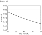
- FIG. 4 is a view illustrating an emissivity ratio according to a ratio of slag and molten iron, and illustrates a total emissivity ratio (e-Slope) according to the ratio of slag (Slag Ratio).
- the total emissivity ratio may become 1, which is close to the emissivity ratio of slag.
- FIG. 5 is a view illustrating a temperature value error according to a ratio of slag and molten iron, and illustrates a temperature value error (Temp. Difference) according to a ratio of slag (Slag Ratio).
- a reference emissivity ratio set in the temperature measurement unit, may be assumed to be an emissivity ratio when a ratio of slag is 40%.
- each ratio of slag may correspond to a temperature value error.
- the correction unit may generate a corrected temperature value, a negative number of a temperature value error corresponding to a ratio measured by the ratio measurement unit.
- the correction unit may generate a corrected temperature value to be greater as a ratio of slag, measured by the ratio measurement unit, is greater as compared with a reference ratio, and may generate a corrected temperature value to be smaller as the ratio of slag, measured by the ratio measurement unit, is smaller as compared with the reference ratio.
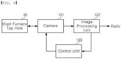
- FIG. 6 is a view illustrating a ratio measurement unit.
- a ratio measurement unit may include a camera 121, an image processing unit 122, and a control unit 123.
- the camera 121 may obtain an image of the blast furnace tap hole 10.
- the camera 121 may be a high-speed camera capable of capturing images 200 times per second, and may have a zoom function.
- the image processing unit 122 may calculate a ratio by identifying slag and molten iron from the image.
- the image processing unit 122 may be implemented as a computing environment, including a processor, a memory, an input device, an output device, and communication connection.
- the control unit 123 may control a capturing range of the camera 121 based on an image analysis result of the image processing unit 122. For example, the control unit 123 may adjust a size of a capturing range by controlling a lens of the camera 121, and may adjust a position of the capturing range by driving the camera 121.
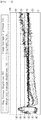
- FIG. 7 is a view illustrating brightness analysis in the captured image of the camera, and illustrates an example of an image, an example of a graph illustrating brightness according to a position of the image, an example of first reference brightness (Threshold 1), an example of second reference brightness (Threshold 2), and an example of brightness corresponding to a boundary point between slag and molten iron.
- the image processing unit included in ratio measurement unit, may calculate a ratio of a pixel, having brightness higher than first and second reference brightness in an image, and a pixel having brightness higher than the first reference brightness and lower than the second reference brightness in the image.
- the image processing unit included in ratio measurement unit, may identify a set of pixels, having brightness lower than the first reference brightness (Threshold 1) in an image, as background, may identify a set of pixels having brightness, higher than the first reference brightness (Threshold 1) and lower than the second reference brightness (Threshold 2) in the image, as molten iron, and may identify a set of pixels, having brightness, higher than the first and second reference brightness (Threshold 1 and Threshold 2) in the image, as slag.
- the pixels may include not only a single pixel but also a set of pixels including a plurality of pixels, adjacent to each other.
- FIG. 8 is a view illustrating position analysis in the captured image of the camera, and illustrates an example of the image, and an example of a reference line 1 to a reference line 3 set in the image.
- a control unit included in a ratio measurement unit, may adjust a capturing range of a camera according to an overall position in a dark region corresponding to background in the image .
- the image may be divided into a region below a reference line 1, a region between the reference line 1 and a reference line 2, a region between the reference line 2 and a reference line 3, and a region above the reference line 3.
- the control unit may allow the capturing range of the camera to move more, as a difference between a ratio of a dark region in the region below the reference line 1 and a ratio of a dark region in the region above the reference line 3.
- the reference line 1 to the reference line 3 may be set based on the analysis result of the image processing unit.
- the reference line 1 to the reference line 3 may be set based on an overall position of a boundary between slag or molten iron and background in an image.
- the reference line 2 may be set in a center line of the reference line 1 to the reference line 3.
- the reference line 2 may be used to set the analysis region described below.
- FIG. 9 is a view illustrating an analysis region in the captured image of the camera, and illustrates an example of an image, and an example of the analysis region set in the image.
- the image processing unit included in ratio measurement unit, may set a reference line 1 and a reference line 3, corresponding to positions of boundaries of a dark region corresponding to the background, respectively, may set a reference line 2 between the reference line 1 and the reference line 3, may set an analysis region including a portion of the reference line 2, and may calculate a ratio of a pixel having brightness higher than second reference brightness in the analysis region, and a pixel having brightness lower than the second reference brightness in the analysis region.
- the time required for image processing of the image processing unit may be reduced, and image intensive analysis to improve the analysis accuracy of the image processing part may be easily implemented.
- the analysis region may be arbitrarily selected from regions, in which a pixel having brightness lower than first reference brightness is substantially not included, without setting the reference line 1 to the reference line 3.
- FIG. 10 is a view illustrating maximum brightness, minimum brightness, and average brightness in the captured image of the camera, and illustrates brightness of molten iron, brightness of an image, and brightness of slag according to a position of the image.
- the image processing unit included in ratio measurement unit, may set first and second reference brightness dependent on at least one among maximum brightness, minimum brightness, and average brightness of the image.
- the overall brightness of the image, obtained by the camera may vary depending on the environment of the blast furnace tap hole.
- the overall brightness may be reflected in the maximum brightness, minimum brightness, and average brightness.
- the blast furnace tap hole temperature measurement device may measure a temperature of the blast furnace tap hole accurately, despite a flexible environment of the blast furnace tap hole.
Landscapes
- Engineering & Computer Science (AREA)
- Mechanical Engineering (AREA)
- General Engineering & Computer Science (AREA)
- Chemical & Material Sciences (AREA)
- Spectroscopy & Molecular Physics (AREA)
- General Physics & Mathematics (AREA)
- Physics & Mathematics (AREA)
- Manufacturing & Machinery (AREA)
- Materials Engineering (AREA)
- Metallurgy (AREA)
- Organic Chemistry (AREA)
- Radiation Pyrometers (AREA)
- Waste-Gas Treatment And Other Accessory Devices For Furnaces (AREA)
- Blast Furnaces (AREA)
Abstract
Description
- The present invention relates to a blast furnace tap hole temperature measurement device.
- Quickly reflecting the precise temperature of a blast furnace tap hole in the operating conditions of an iron making process is important for stabilization of a blast furnace, production efficiency, and energy consumption efficiency.
- According to the related art, a temperature of a blast furnace tap hole is high enough to change a state of some substances, so it is difficult to accurately measure the temperature thereof.
- An aspect of the present disclosure may provide a blast furnace tap hole temperature measurement device capable of accurately measuring a temperature of a tap hole.
- According to an aspect of the present disclosure, a blast furnace tap hole temperature measurement device includes: a temperature measurement unit for measuring a temperature value by measuring first and second wavelength radiation energy of a blast furnace tap hole, and applying the first and second wavelength radiation energy to a reference emissivity ratio; a camera for obtaining an image of the blast furnace tap hole; an image processing unit for calculating a ratio of slag and molten iron by identifying the slag and the molten iron from the image; and a correction unit for generating a final temperature value by applying a corrected temperature value corresponding to a difference between a ratio calculated by the image processing unit and a reference ratio corresponding to the reference emissivity ratio to a temperature value, measured by the temperature measurement unit.
- According to an exemplary embodiment in the present disclosure, a temperature of a blast furnace tap hole may be accurately measured and quickly reflected in the operating conditions of the iron making process, and stabilization of blast furnace, production efficiency, and energy consumption efficiency may be improved.
-
-
FIG. 1 is a view illustrating a blast furnace tap hole temperature measurement device according to an embodiment. -
FIG. 2 is a view illustrating distribution of radiation energy which can be measured by a temperature measurement unit. -
FIG. 3 is a view illustrating emissivity characteristics for each wavelength of slag and molten iron. -
FIG. 4 is a view illustrating an emissivity ratio according to a ratio of slag and molten iron. -
FIG. 5 is a view illustrating a temperature value error according to a ratio of slag and molten iron. -
FIG. 6 is a view illustrating a ratio measurement unit. -
FIG. 7 is a view illustrating brightness analysis in the captured image of the camera. -
FIG. 8 is a view illustrating position analysis in the captured image of the camera. -
FIG. 9 is a view illustrating an analysis region in the captured image of the camera. -
FIG. 10 is a view illustrating maximum brightness, minimum brightness, and average brightness in the captured image of the camera. - Embodiments of the present disclosure will hereinafter be described with reference to the attached drawings. The disclosure may, however, be exemplified in many different forms and should not be construed as being limited to the specific embodiments set forth herein. The shapes and sizes of components shown in the drawings are exaggerated for clarity. Elements having substantially the same or equivalent constitutions and functions are referred to by the same reference numerals throughout the specification.
-
FIG. 1 is a view illustrating a blast furnace tap hole temperature measurement device according to an embodiment. - Referring to
FIG. 1 , a blast furnace tap hole temperature measurement device according to an embodiment may include atemperature measurement unit 110, aratio measurement unit 120, and acorrection unit 130. - The
temperature measurement unit 110 may measure a temperature value of the blastfurnace tap hole 10. For example, thetemperature measurement unit 110 may be a two-wavelength thermometer which measures radiation energy having different wavelengths to generate a temperature value. - The
ratio measurement unit 120 may measure a ratio of slag and molten iron of the blastfurnace tap hole 10. For example, theratio measurement unit 120 may obtain an image of the blastfurnace tap hole 10 and analyze the image to measure a ratio of slag and molten iron. - The
correction unit 130 may generate a final temperature value by applying a corrected temperature value, corresponding to the ratio, measured by theratio measurement unit 120, to a temperature value, measured by thetemperature measurement unit 110. - There is a characteristic that the temperature value, measured by the
temperature measurement unit 110, differs from an actual temperature depending on the ratio of slag and molten iron. In this regard, thecorrection unit 130 corrects the characteristic described above, thereby generating a final temperature value, closer to the actual temperature, as compared with the temperature value, measured by thetemperature measurement unit 110. Accordingly, a temperature of the blastfurnace tap hole 10 may be accurately measured. -
FIG. 2 is a view illustrating distribution of radiation energy which could be measured by a temperature measurement unit, and illustrates radiation energy Eλ,b(λ,T) according to a wavelength λ of a blackbody of a specific temperature T, and radiation energy Eλ(λ,T) according to a wavelength λ of a real surface of a specific temperature T. - Here, the radiation energy Eλ(λ,T) of a real surface may be defined as the product of the radiation energy Eλ,b(λ,T) of the blackbody and the emissivity ελ.
- The two-wavelength thermometer, in which emissivity is set, may measure radiation energy Eλ1 of a first wavelength λ1 and radiation energy Eλ2 of a second wavelength λ2 at a specific temperature, and may generate a temperature value corresponding to a difference value between two types of radiation energy. Here, the relationship between the difference value and the temperature value may be set in accordance with the Stefan-Boltzmann law.
- Here, the relationship could be generalized by
Equation 1. Here, a value, obtained by dividing emissivity ε1 of the first wavelength λ1 by emissivity ε2 of the second wavelength λ2, may be defined as an emissivity ratio.
- The temperature measurement unit may measure first and second wavelength radiation energy Eλ1 and Eλ2 of a blast furnace tap hole, and may apply a reference emissivity ratio to the first and second wavelength radiation energy Eλ1 and Eλ2 to generate a temperature value. For example, the temperature measurement unit may set an emissivity ratio when a ratio of slag and molten iron of the blast furnace tap hole is the reference ratio, as the reference emissivity ratio.
- On the other hand, in the blast furnace tap hole, a slag at the start of tapping may be greater than a ratio of slag at the end of tapping. Thus, the reference ratio may be set as a ratio of average slag in the middle of tapping of the blast furnace tap hole.
-
FIG. 3 is a view illustrating emissivity characteristics for each wavelength of slag (Slag) and molten iron (Steel), and illustrates emissivity according to a wavelength of each of slag and molten iron. - Here, the emissivity of the slag may be hardly affected by a wavelength, while the emissivity of the molten iron may be significantly affected by a wavelength. In other words, an emissivity ratio of the slag may be close to 1, but an emissivity ratio of the molten iron may be not close to 1.
- Thus, the
Equation 1 could be expressed byEquation 2 according to reflection of the emissivity of slag and the emissivity of molten iron. Here, m is the emissivity of molten iron, εs is the emissivity of slag, Am is an area ratio of molten iron, As is an area ratio of slag, and the sum of the area ratio of molten iron and the area ratio of slag is 1.
-
FIG. 4 is a view illustrating an emissivity ratio according to a ratio of slag and molten iron, and illustrates a total emissivity ratio (e-Slope) according to the ratio of slag (Slag Ratio). - As the ratio of slag is higher, the total emissivity ratio may become 1, which is close to the emissivity ratio of slag.
-
FIG. 5 is a view illustrating a temperature value error according to a ratio of slag and molten iron, and illustrates a temperature value error (Temp. Difference) according to a ratio of slag (Slag Ratio). - Here, a reference emissivity ratio, set in the temperature measurement unit, may be assumed to be an emissivity ratio when a ratio of slag is 40%.
- For example, each ratio of slag may correspond to a temperature value error. The correction unit may generate a corrected temperature value, a negative number of a temperature value error corresponding to a ratio measured by the ratio measurement unit.
- For example, the correction unit may generate a corrected temperature value to be greater as a ratio of slag, measured by the ratio measurement unit, is greater as compared with a reference ratio, and may generate a corrected temperature value to be smaller as the ratio of slag, measured by the ratio measurement unit, is smaller as compared with the reference ratio.
-
FIG. 6 is a view illustrating a ratio measurement unit. - Referring to
FIG. 6 , a ratio measurement unit may include acamera 121, animage processing unit 122, and acontrol unit 123. - The
camera 121 may obtain an image of the blastfurnace tap hole 10. For example, thecamera 121 may be a high-speed camera capable of capturing images 200 times per second, and may have a zoom function. - The
image processing unit 122 may calculate a ratio by identifying slag and molten iron from the image. For example, theimage processing unit 122 may be implemented as a computing environment, including a processor, a memory, an input device, an output device, and communication connection. - The
control unit 123 may control a capturing range of thecamera 121 based on an image analysis result of theimage processing unit 122. For example, thecontrol unit 123 may adjust a size of a capturing range by controlling a lens of thecamera 121, and may adjust a position of the capturing range by driving thecamera 121. -
FIG. 7 is a view illustrating brightness analysis in the captured image of the camera, and illustrates an example of an image, an example of a graph illustrating brightness according to a position of the image, an example of first reference brightness (Threshold 1), an example of second reference brightness (Threshold 2), and an example of brightness corresponding to a boundary point between slag and molten iron. - For example, the image processing unit, included in ratio measurement unit, may calculate a ratio of a pixel, having brightness higher than first and second reference brightness in an image, and a pixel having brightness higher than the first reference brightness and lower than the second reference brightness in the image.
- For example, the image processing unit, included in ratio measurement unit, may identify a set of pixels, having brightness lower than the first reference brightness (Threshold 1) in an image, as background, may identify a set of pixels having brightness, higher than the first reference brightness (Threshold 1) and lower than the second reference brightness (Threshold 2) in the image, as molten iron, and may identify a set of pixels, having brightness, higher than the first and second reference brightness (
Threshold 1 and Threshold 2) in the image, as slag. - Here, the pixels, described above and below, may include not only a single pixel but also a set of pixels including a plurality of pixels, adjacent to each other.
-
FIG. 8 is a view illustrating position analysis in the captured image of the camera, and illustrates an example of the image, and an example of areference line 1 to areference line 3 set in the image. - For example, a control unit, included in a ratio measurement unit, may adjust a capturing range of a camera according to an overall position in a dark region corresponding to background in the image . The image may be divided into a region below a
reference line 1, a region between thereference line 1 and areference line 2, a region between thereference line 2 and areference line 3, and a region above thereference line 3. The control unit may allow the capturing range of the camera to move more, as a difference between a ratio of a dark region in the region below thereference line 1 and a ratio of a dark region in the region above thereference line 3. - On the other hand, the
reference line 1 to thereference line 3 may be set based on the analysis result of the image processing unit. For example, thereference line 1 to thereference line 3 may be set based on an overall position of a boundary between slag or molten iron and background in an image. Then, thereference line 2 may be set in a center line of thereference line 1 to thereference line 3. Thereference line 2 may be used to set the analysis region described below. -
FIG. 9 is a view illustrating an analysis region in the captured image of the camera, and illustrates an example of an image, and an example of the analysis region set in the image. - For example, the image processing unit, included in ratio measurement unit, may set a
reference line 1 and areference line 3, corresponding to positions of boundaries of a dark region corresponding to the background, respectively, may set areference line 2 between thereference line 1 and thereference line 3, may set an analysis region including a portion of thereference line 2, and may calculate a ratio of a pixel having brightness higher than second reference brightness in the analysis region, and a pixel having brightness lower than the second reference brightness in the analysis region. - Accordingly, the time required for image processing of the image processing unit may be reduced, and image intensive analysis to improve the analysis accuracy of the image processing part may be easily implemented.
- On the other hand, the analysis region may be arbitrarily selected from regions, in which a pixel having brightness lower than first reference brightness is substantially not included, without setting the
reference line 1 to thereference line 3. -
FIG. 10 is a view illustrating maximum brightness, minimum brightness, and average brightness in the captured image of the camera, and illustrates brightness of molten iron, brightness of an image, and brightness of slag according to a position of the image. - For example, the image processing unit, included in ratio measurement unit, may set first and second reference brightness dependent on at least one among maximum brightness, minimum brightness, and average brightness of the image.
- The overall brightness of the image, obtained by the camera, may vary depending on the environment of the blast furnace tap hole. The overall brightness may be reflected in the maximum brightness, minimum brightness, and average brightness.
- Accordingly, the blast furnace tap hole temperature measurement device according to an embodiment may measure a temperature of the blast furnace tap hole accurately, despite a flexible environment of the blast furnace tap hole.
- While exemplary embodiments have been shown and described above, it will be apparent to those skilled in the art that modifications and variations could be made without departing from the scope of the present invention as defined by the appended claims.
Claims (8)
- A blast furnace tap hole temperature measurement device, comprising:a temperature measurement unit for measuring a temperature value by measuring first and second wavelength radiation energy of a blast furnace tap hole, and applying a reference emissivity ratio to the first and second wavelength radiation energy;a camera for obtaining an image of the blast furnace tap hole;an image processing unit for calculating a ratio of slag and molten iron by identifying the slag and the molten iron from the image; anda correction unit for generating a final temperature value by applying a corrected temperature value, corresponding to a difference between a ratio, calculated by the image processing unit, and a reference ratio, corresponding to the reference emissivity ratio, to a temperature value, measured by the temperature measurement unit.
- The blast furnace tap hole temperature measurement device of claim 1, wherein, when an amount of the slag is greater as compared with the molten iron in the blast furnace tap hole, the correction unit generates the corrected temperature value so that the final temperature value is higher.
- The blast furnace tap hole temperature measurement device of claim 1, wherein the image processing unit calculates a ratio of a pixel having brightness, higher than first and second reference brightness in the image, and a pixel having brightness, higher than the first reference brightness and lower than the second reference brightness in the image.
- The blast furnace tap hole temperature measurement device of claim 1, wherein the image processing unit identifies a set of pixels, having brightness lower than first reference brightness in the image, as a background, identifies a set of pixels, having brightness higher than the first reference brightness and lower than second reference brightness in the image, as the molten iron, and identifies a set of pixels, having brightness higher than the first and second reference brightness in the image, as the slag.
- The blast furnace tap hole temperature measurement device of claim 1, wherein the image processing unit identifies a set of pixels, having brightness lower than first reference brightness in the image, as background, sets a reference line 1 and a reference line 3, corresponding to positions of boundaries of the background, respectively, in the image, sets a reference line 2, between the reference line 1 and the reference line 3 in the image, sets an analysis region including a portion of the reference line 2 in the image, and calculates a ratio of a pixel having brightness higher than the second reference brightness in the analysis region and a pixel having brightness lower than the second reference brightness in the analysis region.
- The blast furnace tap hole temperature measurement device of claim 4, further comprising a control unit for controlling a capturing range of the camera based on a position of the background in the image or a ratio of the background in the image.
- The blast furnace tap hole temperature measurement device of claim 3, wherein the image processing unit sets the first and second reference brightness dependent on at least one among maximum brightness, minimum brightness, and average brightness of the image.
- The blast furnace tap hole temperature measurement device of claim 5, wherein the image processing unit sets the first and second reference brightness dependent on at least one among maximum brightness, minimum brightness, and average brightness of the image.
Applications Claiming Priority (2)
| Application Number | Priority Date | Filing Date | Title |
|---|---|---|---|
| KR1020160168767A KR101867715B1 (en) | 2016-12-12 | 2016-12-12 | Temperature measurement apparatus for tap hole of blast furnace |
| PCT/KR2017/014476 WO2018110921A1 (en) | 2016-12-12 | 2017-12-11 | Blast furnace tap hole temperature measurement device |
Publications (3)
| Publication Number | Publication Date |
|---|---|
| EP3553189A1 true EP3553189A1 (en) | 2019-10-16 |
| EP3553189A4 EP3553189A4 (en) | 2019-12-04 |
| EP3553189B1 EP3553189B1 (en) | 2022-08-17 |
Family
ID=62559034
Family Applications (1)
| Application Number | Title | Priority Date | Filing Date |
|---|---|---|---|
| EP17881506.4A Active EP3553189B1 (en) | 2016-12-12 | 2017-12-11 | Blast furnace tap hole temperature measurement device |
Country Status (7)
| Country | Link |
|---|---|
| EP (1) | EP3553189B1 (en) |
| JP (1) | JP6876802B2 (en) |
| KR (1) | KR101867715B1 (en) |
| CN (1) | CN110073008B (en) |
| BR (1) | BR112019011170B1 (en) |
| ES (1) | ES2929048T3 (en) |
| WO (1) | WO2018110921A1 (en) |
Cited By (1)
| Publication number | Priority date | Publication date | Assignee | Title |
|---|---|---|---|---|
| CN121558184A (en) * | 2026-01-21 | 2026-02-24 | 深圳市红加科技有限公司 | Intelligent measurement method and intelligent measurement device for molten iron temperature |
Families Citing this family (4)
| Publication number | Priority date | Publication date | Assignee | Title |
|---|---|---|---|---|
| KR102135820B1 (en) * | 2018-11-30 | 2020-07-20 | 주식회사 포스코 | Apparatus for judging furnace temperature of blast furnace and method for judging furnace temperature of blast furnace |
| KR102200133B1 (en) * | 2018-11-30 | 2021-01-07 | 주식회사 포스코 | Apparatus and method for measuring blast furnace temperature |
| KR102514756B1 (en) | 2020-12-15 | 2023-03-29 | 주식회사 포스코 | System and method for measuring temperature of molten iron |
| CN113122669B (en) * | 2021-04-22 | 2022-07-26 | 上海应用技术大学 | Blast furnace taphole state monitoring method and system |
Family Cites Families (20)
| Publication number | Priority date | Publication date | Assignee | Title |
|---|---|---|---|---|
| JPH01233329A (en) * | 1988-03-15 | 1989-09-19 | Nippon Steel Corp | Detecting method of temperature of hot metal |
| JPH03103729A (en) * | 1989-09-18 | 1991-04-30 | Nkk Corp | Radiation thermometer for molten iron |
| KR940009668B1 (en) * | 1992-12-30 | 1994-10-15 | 포항종합제철주식회사 | Revision method of molton iron temperature |
| JPH09182953A (en) * | 1995-12-27 | 1997-07-15 | Tokai Carbon Co Ltd | Slag detection method |
| JP3677857B2 (en) * | 1996-03-21 | 2005-08-03 | Jfeスチール株式会社 | Coke temperature distribution measurement method in raceway |
| JPH10130040A (en) * | 1996-10-25 | 1998-05-19 | Nkk Corp | Waste heat recovery method and apparatus for granulated slag production equipment |
| US6197086B1 (en) * | 1997-11-13 | 2001-03-06 | Bethlehem Steel Corporation | System and method for minimizing slag carryover during the production of steel |
| US5968227A (en) * | 1997-11-13 | 1999-10-19 | Bethlehem Steel Corporation | System and method for minimizing slag carryover during the tapping of a BOF converter in the production of steel |
| US6562285B1 (en) * | 2000-11-15 | 2003-05-13 | Metallurgical Sensors, Inc. | Method and apparatus for detecting slag carryover |
| JP4238165B2 (en) * | 2004-03-22 | 2009-03-11 | 新日本製鐵株式会社 | Measuring method of dredging diameter of blast furnace outlet |
| JP4516854B2 (en) * | 2004-09-24 | 2010-08-04 | 新日本製鐵株式会社 | Blast furnace tapping temperature measuring method and measuring device |
| JP4146420B2 (en) | 2004-12-24 | 2008-09-10 | 新日本製鐵株式会社 | Blast furnace tapping temperature and hot metal / molten slag mixing ratio measurement method |
| JP4714607B2 (en) * | 2006-03-14 | 2011-06-29 | 新日本製鐵株式会社 | Blast furnace outflow measurement system, blast furnace outflow measurement method, and computer program |
| JP4669420B2 (en) * | 2006-03-14 | 2011-04-13 | 新日本製鐵株式会社 | Blast furnace tapping temperature measuring system, blast furnace tapping temperature measuring method, and computer program |
| WO2010064727A1 (en) * | 2008-12-03 | 2010-06-10 | 新日本製鐵株式会社 | Method of determining temperature of molten pig iron and method of operating blast furnace using same |
| JP2015055547A (en) * | 2013-09-12 | 2015-03-23 | 株式会社日立製作所 | Multi-wavelength radiation thermometer and multi-wavelength radiation temperature measurement method |
| JP6302228B2 (en) * | 2013-12-09 | 2018-03-28 | 新日鐵住金株式会社 | Molten slag flow rate measuring method, molten slag flow rate measuring system, and computer program |
| JP6242329B2 (en) * | 2014-05-28 | 2017-12-06 | 株式会社神戸製鋼所 | Hot metal quantity measuring method in vertical furnace and measuring device |
| CN105333962B (en) * | 2014-06-18 | 2018-06-22 | 中微半导体设备(上海)有限公司 | A kind of thermometry and system for correcting two waveband temperature measurement error |
| JP6164173B2 (en) * | 2014-07-29 | 2017-07-19 | Jfeスチール株式会社 | Converter discharge flow determination device, converter discharge flow determination method, hot metal pretreatment method, and converter pretreatment operation method |
-
2016
- 2016-12-12 KR KR1020160168767A patent/KR101867715B1/en active Active
-
2017
- 2017-12-11 WO PCT/KR2017/014476 patent/WO2018110921A1/en not_active Ceased
- 2017-12-11 BR BR112019011170-0A patent/BR112019011170B1/en active IP Right Grant
- 2017-12-11 ES ES17881506T patent/ES2929048T3/en active Active
- 2017-12-11 EP EP17881506.4A patent/EP3553189B1/en active Active
- 2017-12-11 CN CN201780076185.6A patent/CN110073008B/en active Active
- 2017-12-11 JP JP2019531125A patent/JP6876802B2/en active Active
Cited By (1)
| Publication number | Priority date | Publication date | Assignee | Title |
|---|---|---|---|---|
| CN121558184A (en) * | 2026-01-21 | 2026-02-24 | 深圳市红加科技有限公司 | Intelligent measurement method and intelligent measurement device for molten iron temperature |
Also Published As
| Publication number | Publication date |
|---|---|
| BR112019011170A2 (en) | 2019-10-01 |
| KR101867715B1 (en) | 2018-06-14 |
| CN110073008A (en) | 2019-07-30 |
| JP2020501158A (en) | 2020-01-16 |
| ES2929048T3 (en) | 2022-11-24 |
| BR112019011170B1 (en) | 2022-11-16 |
| EP3553189B1 (en) | 2022-08-17 |
| WO2018110921A1 (en) | 2018-06-21 |
| JP6876802B2 (en) | 2021-05-26 |
| EP3553189A4 (en) | 2019-12-04 |
| CN110073008B (en) | 2021-10-29 |
Similar Documents
| Publication | Publication Date | Title |
|---|---|---|
| EP3553189B1 (en) | Blast furnace tap hole temperature measurement device | |
| US9286859B2 (en) | Brightness measurement method and brightness adjustment device for display elements | |
| US11162899B2 (en) | Wear amount measuring device and wear amount measuring method | |
| JP2011117777A (en) | Calibration means, calibration method and program | |
| US9756304B2 (en) | Image-acquisition apparatus for performing distance measurement using parallax | |
| JP2008292324A (en) | Surface temperature measuring method and surface temperature measuring apparatus | |
| CN110971810A (en) | Movement lens return difference processing method and device | |
| JP6738553B2 (en) | Change degree deriving device, change degree deriving system, change degree deriving method and program | |
| CN103123281A (en) | Non-contact temperature measuring method | |
| US9992489B2 (en) | Image sensor calibration | |
| CN103852186B (en) | Non-contact temperature measuring method | |
| US9664568B2 (en) | Extended temperature mapping process of a furnace enclosure with multi-spectral image-capturing device | |
| JP7195087B2 (en) | Focus adjustment support device and focus adjustment support method | |
| EP3460390A1 (en) | Displacement measurement device, measurement system, and displacement measurement method | |
| MX2025001109A (en) | Temperature measurement device and temperature measurement method | |
| JP2009047611A (en) | Surface temperature measuring method and surface temperature measuring apparatus | |
| CN113503968A (en) | Temperature measurement method, device and equipment based on in-furnace image and readable storage medium | |
| US20250251287A1 (en) | Temperature measurement method, temperature measurement apparatus, temperature control method, temperature control apparatus, method for manufacturing steel material, and facility for manufacturing steel material | |
| WO2016203902A1 (en) | Optical characteristic measuring apparatus and setting method for optical characteristic measuring apparatus | |
| JP7043278B2 (en) | Emissivity measuring device, temperature measuring device, emissivity measuring method and temperature measuring method | |
| KR101637552B1 (en) | Apparatus and Method for compensating irregular image for lense | |
| CN105115908A (en) | Visual metal rust spot detecting device and method adopting optimal spectral band selecting | |
| US11099071B2 (en) | Imaging condition evaluation device and imaging condition evaluation method | |
| CN102519622B (en) | Method for dynamic measuring temperature and shape of valve electric upsetting forming workpiece | |
| CN114414060A (en) | Measuring apparatus |
Legal Events
| Date | Code | Title | Description |
|---|---|---|---|
| STAA | Information on the status of an ep patent application or granted ep patent |
Free format text: STATUS: THE INTERNATIONAL PUBLICATION HAS BEEN MADE |
|
| PUAI | Public reference made under article 153(3) epc to a published international application that has entered the european phase |
Free format text: ORIGINAL CODE: 0009012 |
|
| STAA | Information on the status of an ep patent application or granted ep patent |
Free format text: STATUS: REQUEST FOR EXAMINATION WAS MADE |
|
| 17P | Request for examination filed |
Effective date: 20190604 |
|
| AK | Designated contracting states |
Kind code of ref document: A1 Designated state(s): AL AT BE BG CH CY CZ DE DK EE ES FI FR GB GR HR HU IE IS IT LI LT LU LV MC MK MT NL NO PL PT RO RS SE SI SK SM TR |
|
| AX | Request for extension of the european patent |
Extension state: BA ME |
|
| A4 | Supplementary search report drawn up and despatched |
Effective date: 20191107 |
|
| RIC1 | Information provided on ipc code assigned before grant |
Ipc: F27B 1/28 20060101ALI20191031BHEP Ipc: F27D 21/00 20060101ALI20191031BHEP Ipc: C21B 7/24 20060101AFI20191031BHEP Ipc: G01J 5/52 20060101ALI20191031BHEP Ipc: G01J 5/00 20060101ALI20191031BHEP Ipc: C21B 7/12 20060101ALI20191031BHEP Ipc: F27D 19/00 20060101ALI20191031BHEP Ipc: F27D 21/02 20060101ALI20191031BHEP Ipc: F27B 1/21 20060101ALI20191031BHEP |
|
| DAV | Request for validation of the european patent (deleted) | ||
| DAX | Request for extension of the european patent (deleted) | ||
| GRAP | Despatch of communication of intention to grant a patent |
Free format text: ORIGINAL CODE: EPIDOSNIGR1 |
|
| STAA | Information on the status of an ep patent application or granted ep patent |
Free format text: STATUS: GRANT OF PATENT IS INTENDED |
|
| INTG | Intention to grant announced |
Effective date: 20220307 |
|
| GRAS | Grant fee paid |
Free format text: ORIGINAL CODE: EPIDOSNIGR3 |
|
| GRAA | (expected) grant |
Free format text: ORIGINAL CODE: 0009210 |
|
| STAA | Information on the status of an ep patent application or granted ep patent |
Free format text: STATUS: THE PATENT HAS BEEN GRANTED |
|
| AK | Designated contracting states |
Kind code of ref document: B1 Designated state(s): AL AT BE BG CH CY CZ DE DK EE ES FI FR GB GR HR HU IE IS IT LI LT LU LV MC MK MT NL NO PL PT RO RS SE SI SK SM TR |
|
| REG | Reference to a national code |
Ref country code: CH Ref legal event code: EP |
|
| REG | Reference to a national code |
Ref country code: DE Ref legal event code: R096 Ref document number: 602017060858 Country of ref document: DE |
|
| REG | Reference to a national code |
Ref country code: IE Ref legal event code: FG4D |
|
| REG | Reference to a national code |
Ref country code: AT Ref legal event code: REF Ref document number: 1512205 Country of ref document: AT Kind code of ref document: T Effective date: 20220915 |
|
| RAP4 | Party data changed (patent owner data changed or rights of a patent transferred) |
Owner name: POSCO HOLDINGS INC. |
|
| REG | Reference to a national code |
Ref country code: NL Ref legal event code: FP |
|
| REG | Reference to a national code |
Ref country code: ES Ref legal event code: FG2A Ref document number: 2929048 Country of ref document: ES Kind code of ref document: T3 Effective date: 20221124 |
|
| REG | Reference to a national code |
Ref country code: LT Ref legal event code: MG9D |
|
| REG | Reference to a national code |
Ref country code: BE Ref legal event code: HC Owner name: POSCO HOLDINGS INC.; KR Free format text: DETAILS ASSIGNMENT: CHANGE OF OWNER(S), CHANGE OF OWNER(S) NAME; FORMER OWNER NAME: POSCO Effective date: 20221114 |
|
| PG25 | Lapsed in a contracting state [announced via postgrant information from national office to epo] |
Ref country code: SE Free format text: LAPSE BECAUSE OF FAILURE TO SUBMIT A TRANSLATION OF THE DESCRIPTION OR TO PAY THE FEE WITHIN THE PRESCRIBED TIME-LIMIT Effective date: 20220817 Ref country code: RS Free format text: LAPSE BECAUSE OF FAILURE TO SUBMIT A TRANSLATION OF THE DESCRIPTION OR TO PAY THE FEE WITHIN THE PRESCRIBED TIME-LIMIT Effective date: 20220817 Ref country code: PT Free format text: LAPSE BECAUSE OF FAILURE TO SUBMIT A TRANSLATION OF THE DESCRIPTION OR TO PAY THE FEE WITHIN THE PRESCRIBED TIME-LIMIT Effective date: 20221219 Ref country code: NO Free format text: LAPSE BECAUSE OF FAILURE TO SUBMIT A TRANSLATION OF THE DESCRIPTION OR TO PAY THE FEE WITHIN THE PRESCRIBED TIME-LIMIT Effective date: 20221117 Ref country code: LV Free format text: LAPSE BECAUSE OF FAILURE TO SUBMIT A TRANSLATION OF THE DESCRIPTION OR TO PAY THE FEE WITHIN THE PRESCRIBED TIME-LIMIT Effective date: 20220817 Ref country code: LT Free format text: LAPSE BECAUSE OF FAILURE TO SUBMIT A TRANSLATION OF THE DESCRIPTION OR TO PAY THE FEE WITHIN THE PRESCRIBED TIME-LIMIT Effective date: 20220817 Ref country code: FI Free format text: LAPSE BECAUSE OF FAILURE TO SUBMIT A TRANSLATION OF THE DESCRIPTION OR TO PAY THE FEE WITHIN THE PRESCRIBED TIME-LIMIT Effective date: 20220817 |
|
| RAP2 | Party data changed (patent owner data changed or rights of a patent transferred) |
Owner name: POSCO CO., LTD |
|
| REG | Reference to a national code |
Ref country code: DE Ref legal event code: R081 Ref document number: 602017060858 Country of ref document: DE Owner name: POSCO CO., LTD, POHANG-SI, KR Free format text: FORMER OWNER: POSCO, POHANG-SI, GYEONGSANGBUK-DO, KR Ref country code: DE Ref legal event code: R081 Ref document number: 602017060858 Country of ref document: DE Owner name: POSCO CO., LTD, POHANG- SI, KR Free format text: FORMER OWNER: POSCO, POHANG-SI, GYEONGSANGBUK-DO, KR Ref country code: DE Ref legal event code: R081 Ref document number: 602017060858 Country of ref document: DE Owner name: POSCO HOLDINGS INC., KR Free format text: FORMER OWNER: POSCO, POHANG-SI, GYEONGSANGBUK-DO, KR |
|
| PG25 | Lapsed in a contracting state [announced via postgrant information from national office to epo] |
Ref country code: PL Free format text: LAPSE BECAUSE OF FAILURE TO SUBMIT A TRANSLATION OF THE DESCRIPTION OR TO PAY THE FEE WITHIN THE PRESCRIBED TIME-LIMIT Effective date: 20220817 Ref country code: IS Free format text: LAPSE BECAUSE OF FAILURE TO SUBMIT A TRANSLATION OF THE DESCRIPTION OR TO PAY THE FEE WITHIN THE PRESCRIBED TIME-LIMIT Effective date: 20221217 Ref country code: HR Free format text: LAPSE BECAUSE OF FAILURE TO SUBMIT A TRANSLATION OF THE DESCRIPTION OR TO PAY THE FEE WITHIN THE PRESCRIBED TIME-LIMIT Effective date: 20220817 Ref country code: GR Free format text: LAPSE BECAUSE OF FAILURE TO SUBMIT A TRANSLATION OF THE DESCRIPTION OR TO PAY THE FEE WITHIN THE PRESCRIBED TIME-LIMIT Effective date: 20221118 |
|
| REG | Reference to a national code |
Ref country code: DE Ref legal event code: R081 Ref document number: 602017060858 Country of ref document: DE Owner name: POSCO CO., LTD, POHANG-SI, KR Free format text: FORMER OWNER: POSCO HOLDINGS INC., SEOUL, KR Ref country code: DE Ref legal event code: R081 Ref document number: 602017060858 Country of ref document: DE Owner name: POSCO CO., LTD, POHANG- SI, KR Free format text: FORMER OWNER: POSCO HOLDINGS INC., SEOUL, KR |
|
| PG25 | Lapsed in a contracting state [announced via postgrant information from national office to epo] |
Ref country code: SM Free format text: LAPSE BECAUSE OF FAILURE TO SUBMIT A TRANSLATION OF THE DESCRIPTION OR TO PAY THE FEE WITHIN THE PRESCRIBED TIME-LIMIT Effective date: 20220817 Ref country code: RO Free format text: LAPSE BECAUSE OF FAILURE TO SUBMIT A TRANSLATION OF THE DESCRIPTION OR TO PAY THE FEE WITHIN THE PRESCRIBED TIME-LIMIT Effective date: 20220817 Ref country code: DK Free format text: LAPSE BECAUSE OF FAILURE TO SUBMIT A TRANSLATION OF THE DESCRIPTION OR TO PAY THE FEE WITHIN THE PRESCRIBED TIME-LIMIT Effective date: 20220817 Ref country code: CZ Free format text: LAPSE BECAUSE OF FAILURE TO SUBMIT A TRANSLATION OF THE DESCRIPTION OR TO PAY THE FEE WITHIN THE PRESCRIBED TIME-LIMIT Effective date: 20220817 |
|
| REG | Reference to a national code |
Ref country code: DE Ref legal event code: R097 Ref document number: 602017060858 Country of ref document: DE |
|
| PG25 | Lapsed in a contracting state [announced via postgrant information from national office to epo] |
Ref country code: SK Free format text: LAPSE BECAUSE OF FAILURE TO SUBMIT A TRANSLATION OF THE DESCRIPTION OR TO PAY THE FEE WITHIN THE PRESCRIBED TIME-LIMIT Effective date: 20220817 Ref country code: EE Free format text: LAPSE BECAUSE OF FAILURE TO SUBMIT A TRANSLATION OF THE DESCRIPTION OR TO PAY THE FEE WITHIN THE PRESCRIBED TIME-LIMIT Effective date: 20220817 |
|
| PLBE | No opposition filed within time limit |
Free format text: ORIGINAL CODE: 0009261 |
|
| STAA | Information on the status of an ep patent application or granted ep patent |
Free format text: STATUS: NO OPPOSITION FILED WITHIN TIME LIMIT |
|
| PG25 | Lapsed in a contracting state [announced via postgrant information from national office to epo] |
Ref country code: AL Free format text: LAPSE BECAUSE OF FAILURE TO SUBMIT A TRANSLATION OF THE DESCRIPTION OR TO PAY THE FEE WITHIN THE PRESCRIBED TIME-LIMIT Effective date: 20220817 |
|
| 26N | No opposition filed |
Effective date: 20230519 |
|
| REG | Reference to a national code |
Ref country code: CH Ref legal event code: PL |
|
| REG | Reference to a national code |
Ref country code: AT Ref legal event code: UEP Ref document number: 1512205 Country of ref document: AT Kind code of ref document: T Effective date: 20220817 |
|
| GBPC | Gb: european patent ceased through non-payment of renewal fee |
Effective date: 20221211 |
|
| PG25 | Lapsed in a contracting state [announced via postgrant information from national office to epo] |
Ref country code: SI Free format text: LAPSE BECAUSE OF FAILURE TO SUBMIT A TRANSLATION OF THE DESCRIPTION OR TO PAY THE FEE WITHIN THE PRESCRIBED TIME-LIMIT Effective date: 20220817 Ref country code: LU Free format text: LAPSE BECAUSE OF NON-PAYMENT OF DUE FEES Effective date: 20221211 |
|
| PG25 | Lapsed in a contracting state [announced via postgrant information from national office to epo] |
Ref country code: LI Free format text: LAPSE BECAUSE OF NON-PAYMENT OF DUE FEES Effective date: 20221231 Ref country code: IE Free format text: LAPSE BECAUSE OF NON-PAYMENT OF DUE FEES Effective date: 20221211 Ref country code: GB Free format text: LAPSE BECAUSE OF NON-PAYMENT OF DUE FEES Effective date: 20221211 Ref country code: CH Free format text: LAPSE BECAUSE OF NON-PAYMENT OF DUE FEES Effective date: 20221231 |
|
| PG25 | Lapsed in a contracting state [announced via postgrant information from national office to epo] |
Ref country code: FR Free format text: LAPSE BECAUSE OF NON-PAYMENT OF DUE FEES Effective date: 20221231 |
|
| PG25 | Lapsed in a contracting state [announced via postgrant information from national office to epo] |
Ref country code: HU Free format text: LAPSE BECAUSE OF FAILURE TO SUBMIT A TRANSLATION OF THE DESCRIPTION OR TO PAY THE FEE WITHIN THE PRESCRIBED TIME-LIMIT; INVALID AB INITIO Effective date: 20171211 |
|
| PG25 | Lapsed in a contracting state [announced via postgrant information from national office to epo] |
Ref country code: CY Free format text: LAPSE BECAUSE OF FAILURE TO SUBMIT A TRANSLATION OF THE DESCRIPTION OR TO PAY THE FEE WITHIN THE PRESCRIBED TIME-LIMIT Effective date: 20220817 |
|
| PG25 | Lapsed in a contracting state [announced via postgrant information from national office to epo] |
Ref country code: MK Free format text: LAPSE BECAUSE OF FAILURE TO SUBMIT A TRANSLATION OF THE DESCRIPTION OR TO PAY THE FEE WITHIN THE PRESCRIBED TIME-LIMIT Effective date: 20220817 Ref country code: IT Free format text: LAPSE BECAUSE OF FAILURE TO SUBMIT A TRANSLATION OF THE DESCRIPTION OR TO PAY THE FEE WITHIN THE PRESCRIBED TIME-LIMIT Effective date: 20220817 |
|
| PG25 | Lapsed in a contracting state [announced via postgrant information from national office to epo] |
Ref country code: MC Free format text: LAPSE BECAUSE OF FAILURE TO SUBMIT A TRANSLATION OF THE DESCRIPTION OR TO PAY THE FEE WITHIN THE PRESCRIBED TIME-LIMIT Effective date: 20220817 |
|
| PG25 | Lapsed in a contracting state [announced via postgrant information from national office to epo] |
Ref country code: MC Free format text: LAPSE BECAUSE OF FAILURE TO SUBMIT A TRANSLATION OF THE DESCRIPTION OR TO PAY THE FEE WITHIN THE PRESCRIBED TIME-LIMIT Effective date: 20220817 |
|
| PG25 | Lapsed in a contracting state [announced via postgrant information from national office to epo] |
Ref country code: BG Free format text: LAPSE BECAUSE OF FAILURE TO SUBMIT A TRANSLATION OF THE DESCRIPTION OR TO PAY THE FEE WITHIN THE PRESCRIBED TIME-LIMIT Effective date: 20220817 |
|
| PG25 | Lapsed in a contracting state [announced via postgrant information from national office to epo] |
Ref country code: MT Free format text: LAPSE BECAUSE OF FAILURE TO SUBMIT A TRANSLATION OF THE DESCRIPTION OR TO PAY THE FEE WITHIN THE PRESCRIBED TIME-LIMIT Effective date: 20220817 |
|
| PG25 | Lapsed in a contracting state [announced via postgrant information from national office to epo] |
Ref country code: TR Free format text: LAPSE BECAUSE OF FAILURE TO SUBMIT A TRANSLATION OF THE DESCRIPTION OR TO PAY THE FEE WITHIN THE PRESCRIBED TIME-LIMIT Effective date: 20220817 |
|
| PGFP | Annual fee paid to national office [announced via postgrant information from national office to epo] |
Ref country code: NL Payment date: 20251105 Year of fee payment: 9 |
|
| PGFP | Annual fee paid to national office [announced via postgrant information from national office to epo] |
Ref country code: DE Payment date: 20251105 Year of fee payment: 9 |
|
| PGFP | Annual fee paid to national office [announced via postgrant information from national office to epo] |
Ref country code: AT Payment date: 20251105 Year of fee payment: 9 |
|
| PGFP | Annual fee paid to national office [announced via postgrant information from national office to epo] |
Ref country code: BE Payment date: 20251105 Year of fee payment: 9 |
|
| PGFP | Annual fee paid to national office [announced via postgrant information from national office to epo] |
Ref country code: ES Payment date: 20260122 Year of fee payment: 9 |