EP3553063B1 - Compound and organic solar cell comprising same - Google Patents
Compound and organic solar cell comprising same Download PDFInfo
- Publication number
- EP3553063B1 EP3553063B1 EP18770716.1A EP18770716A EP3553063B1 EP 3553063 B1 EP3553063 B1 EP 3553063B1 EP 18770716 A EP18770716 A EP 18770716A EP 3553063 B1 EP3553063 B1 EP 3553063B1
- Authority
- EP
- European Patent Office
- Prior art keywords
- group
- substituted
- unsubstituted
- compound
- present specification
- Prior art date
- Legal status (The legal status is an assumption and is not a legal conclusion. Google has not performed a legal analysis and makes no representation as to the accuracy of the status listed.)
- Active
Links
Images

Classifications
-
- C—CHEMISTRY; METALLURGY
- C07—ORGANIC CHEMISTRY
- C07D—HETEROCYCLIC COMPOUNDS
- C07D495/00—Heterocyclic compounds containing in the condensed system at least one hetero ring having sulfur atoms as the only ring hetero atoms
- C07D495/02—Heterocyclic compounds containing in the condensed system at least one hetero ring having sulfur atoms as the only ring hetero atoms in which the condensed system contains two hetero rings
- C07D495/04—Ortho-condensed systems
-
- C—CHEMISTRY; METALLURGY
- C07—ORGANIC CHEMISTRY
- C07D—HETEROCYCLIC COMPOUNDS
- C07D417/00—Heterocyclic compounds containing two or more hetero rings, at least one ring having nitrogen and sulfur atoms as the only ring hetero atoms, not provided for by group C07D415/00
- C07D417/14—Heterocyclic compounds containing two or more hetero rings, at least one ring having nitrogen and sulfur atoms as the only ring hetero atoms, not provided for by group C07D415/00 containing three or more hetero rings
-
- H—ELECTRICITY
- H10—SEMICONDUCTOR DEVICES; ELECTRIC SOLID-STATE DEVICES NOT OTHERWISE PROVIDED FOR
- H10K—ORGANIC ELECTRIC SOLID-STATE DEVICES
- H10K30/00—Organic devices sensitive to infrared radiation, light, electromagnetic radiation of shorter wavelength or corpuscular radiation
- H10K30/20—Organic devices sensitive to infrared radiation, light, electromagnetic radiation of shorter wavelength or corpuscular radiation comprising organic-organic junctions, e.g. donor-acceptor junctions
-
- H—ELECTRICITY
- H10—SEMICONDUCTOR DEVICES; ELECTRIC SOLID-STATE DEVICES NOT OTHERWISE PROVIDED FOR
- H10K—ORGANIC ELECTRIC SOLID-STATE DEVICES
- H10K85/00—Organic materials used in the body or electrodes of devices covered by this subclass
- H10K85/10—Organic polymers or oligomers
- H10K85/111—Organic polymers or oligomers comprising aromatic, heteroaromatic, or aryl chains, e.g. polyaniline, polyphenylene or polyphenylene vinylene
- H10K85/113—Heteroaromatic compounds comprising sulfur or selene, e.g. polythiophene
-
- H—ELECTRICITY
- H10—SEMICONDUCTOR DEVICES; ELECTRIC SOLID-STATE DEVICES NOT OTHERWISE PROVIDED FOR
- H10K—ORGANIC ELECTRIC SOLID-STATE DEVICES
- H10K85/00—Organic materials used in the body or electrodes of devices covered by this subclass
- H10K85/60—Organic compounds having low molecular weight
- H10K85/615—Polycyclic condensed aromatic hydrocarbons, e.g. anthracene
- H10K85/621—Aromatic anhydride or imide compounds, e.g. perylene tetra-carboxylic dianhydride or perylene tetracarboxylic di-imide
-
- H—ELECTRICITY
- H10—SEMICONDUCTOR DEVICES; ELECTRIC SOLID-STATE DEVICES NOT OTHERWISE PROVIDED FOR
- H10K—ORGANIC ELECTRIC SOLID-STATE DEVICES
- H10K85/00—Organic materials used in the body or electrodes of devices covered by this subclass
- H10K85/60—Organic compounds having low molecular weight
- H10K85/615—Polycyclic condensed aromatic hydrocarbons, e.g. anthracene
- H10K85/626—Polycyclic condensed aromatic hydrocarbons, e.g. anthracene containing more than one polycyclic condensed aromatic rings, e.g. bis-anthracene
-
- H—ELECTRICITY
- H10—SEMICONDUCTOR DEVICES; ELECTRIC SOLID-STATE DEVICES NOT OTHERWISE PROVIDED FOR
- H10K—ORGANIC ELECTRIC SOLID-STATE DEVICES
- H10K85/00—Organic materials used in the body or electrodes of devices covered by this subclass
- H10K85/60—Organic compounds having low molecular weight
- H10K85/649—Aromatic compounds comprising a hetero atom
- H10K85/655—Aromatic compounds comprising a hetero atom comprising only sulfur as heteroatom
-
- H—ELECTRICITY
- H10—SEMICONDUCTOR DEVICES; ELECTRIC SOLID-STATE DEVICES NOT OTHERWISE PROVIDED FOR
- H10K—ORGANIC ELECTRIC SOLID-STATE DEVICES
- H10K85/00—Organic materials used in the body or electrodes of devices covered by this subclass
- H10K85/60—Organic compounds having low molecular weight
- H10K85/649—Aromatic compounds comprising a hetero atom
- H10K85/656—Aromatic compounds comprising a hetero atom comprising two or more different heteroatoms per ring
-
- H—ELECTRICITY
- H10—SEMICONDUCTOR DEVICES; ELECTRIC SOLID-STATE DEVICES NOT OTHERWISE PROVIDED FOR
- H10K—ORGANIC ELECTRIC SOLID-STATE DEVICES
- H10K85/00—Organic materials used in the body or electrodes of devices covered by this subclass
- H10K85/60—Organic compounds having low molecular weight
- H10K85/649—Aromatic compounds comprising a hetero atom
- H10K85/657—Polycyclic condensed heteroaromatic hydrocarbons
- H10K85/6576—Polycyclic condensed heteroaromatic hydrocarbons comprising only sulfur in the heteroaromatic polycondensed ring system, e.g. benzothiophene
-
- H—ELECTRICITY
- H10—SEMICONDUCTOR DEVICES; ELECTRIC SOLID-STATE DEVICES NOT OTHERWISE PROVIDED FOR
- H10K—ORGANIC ELECTRIC SOLID-STATE DEVICES
- H10K2102/00—Constructional details relating to the organic devices covered by this subclass
- H10K2102/10—Transparent electrodes, e.g. using graphene
- H10K2102/101—Transparent electrodes, e.g. using graphene comprising transparent conductive oxides [TCO]
- H10K2102/103—Transparent electrodes, e.g. using graphene comprising transparent conductive oxides [TCO] comprising indium oxides, e.g. ITO
-
- H—ELECTRICITY
- H10—SEMICONDUCTOR DEVICES; ELECTRIC SOLID-STATE DEVICES NOT OTHERWISE PROVIDED FOR
- H10K—ORGANIC ELECTRIC SOLID-STATE DEVICES
- H10K30/00—Organic devices sensitive to infrared radiation, light, electromagnetic radiation of shorter wavelength or corpuscular radiation
- H10K30/10—Organic devices sensitive to infrared radiation, light, electromagnetic radiation of shorter wavelength or corpuscular radiation comprising heterojunctions between organic semiconductors and inorganic semiconductors
- H10K30/15—Sensitised wide-bandgap semiconductor devices, e.g. dye-sensitised TiO2
- H10K30/152—Sensitised wide-bandgap semiconductor devices, e.g. dye-sensitised TiO2 the wide bandgap semiconductor comprising zinc oxide, e.g. ZnO
-
- H—ELECTRICITY
- H10—SEMICONDUCTOR DEVICES; ELECTRIC SOLID-STATE DEVICES NOT OTHERWISE PROVIDED FOR
- H10K—ORGANIC ELECTRIC SOLID-STATE DEVICES
- H10K30/00—Organic devices sensitive to infrared radiation, light, electromagnetic radiation of shorter wavelength or corpuscular radiation
- H10K30/30—Organic devices sensitive to infrared radiation, light, electromagnetic radiation of shorter wavelength or corpuscular radiation comprising bulk heterojunctions, e.g. interpenetrating networks of donor and acceptor material domains
-
- H—ELECTRICITY
- H10—SEMICONDUCTOR DEVICES; ELECTRIC SOLID-STATE DEVICES NOT OTHERWISE PROVIDED FOR
- H10K—ORGANIC ELECTRIC SOLID-STATE DEVICES
- H10K30/00—Organic devices sensitive to infrared radiation, light, electromagnetic radiation of shorter wavelength or corpuscular radiation
- H10K30/50—Photovoltaic [PV] devices
-
- H—ELECTRICITY
- H10—SEMICONDUCTOR DEVICES; ELECTRIC SOLID-STATE DEVICES NOT OTHERWISE PROVIDED FOR
- H10K—ORGANIC ELECTRIC SOLID-STATE DEVICES
- H10K30/00—Organic devices sensitive to infrared radiation, light, electromagnetic radiation of shorter wavelength or corpuscular radiation
- H10K30/80—Constructional details
- H10K30/81—Electrodes
- H10K30/82—Transparent electrodes, e.g. indium tin oxide [ITO] electrodes
-
- H—ELECTRICITY
- H10—SEMICONDUCTOR DEVICES; ELECTRIC SOLID-STATE DEVICES NOT OTHERWISE PROVIDED FOR
- H10K—ORGANIC ELECTRIC SOLID-STATE DEVICES
- H10K85/00—Organic materials used in the body or electrodes of devices covered by this subclass
- H10K85/10—Organic polymers or oligomers
- H10K85/151—Copolymers
-
- Y—GENERAL TAGGING OF NEW TECHNOLOGICAL DEVELOPMENTS; GENERAL TAGGING OF CROSS-SECTIONAL TECHNOLOGIES SPANNING OVER SEVERAL SECTIONS OF THE IPC; TECHNICAL SUBJECTS COVERED BY FORMER USPC CROSS-REFERENCE ART COLLECTIONS [XRACs] AND DIGESTS
- Y02—TECHNOLOGIES OR APPLICATIONS FOR MITIGATION OR ADAPTATION AGAINST CLIMATE CHANGE
- Y02E—REDUCTION OF GREENHOUSE GAS [GHG] EMISSIONS, RELATED TO ENERGY GENERATION, TRANSMISSION OR DISTRIBUTION
- Y02E10/00—Energy generation through renewable energy sources
- Y02E10/50—Photovoltaic [PV] energy
- Y02E10/549—Organic PV cells
Definitions
- the present specification relates to a compound and an organic solar cell including the same.
- An organic solar cell is a device which may directly convert solar energy into electric energy by applying a photovoltaic effect.
- a solar cell may be divided into an inorganic solar cell and an organic solar cell, depending on the materials constituting a thin film.
- Typical solar cells are made through a p-n junction by doping crystalline silicon (Si), which is an inorganic semiconductor. Electrons and holes generated by absorbing light diffuse to p-n junction points and move to an electrode while being accelerated by the electric field.
- the power conversion efficiency in this process is defined as the ratio of electric power given to an external circuit and solar power entering the solar cell, and the efficiency have reached approximately 24% when measured under a currently standardized virtual solar irradiation condition.
- inorganic solar cells in the related art have already shown the limitation in economic feasibility and material demands and supplies, an organic semiconductor solar cell, which is easily processed and inexpensive and has various functionalities, has come into the spotlight as a long-term alternative energy source.
- the solar cell it is important to increase efficiency so as to output as much electric energy as possible from solar energy.
- One of the reasons for the charge loss is the dissipation of generated electrons and holes due to recombination.
- Various methods have been proposed to deliver generated electrons and holes to an electrode without loss, but additional processes are required in most cases, and accordingly, manufacturing costs may be increased.
- KR 2015 0113631 A and KR 2016 0097766 A disclose heteroaromatic compounds for use in organic solar cells.
- An object of the present specification is to provide a compound and an organic solar cell including the same.
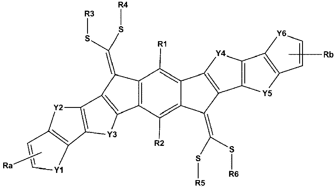
- the invention provides a compound represented by one of the following Formulae 1, A and B: wherein, in Formula 1,
- the invention also provides an organic solar cell comprising:
- sulfur (S) may be introduced into an alkyl chain. Accordingly, crystallinity due to the chalcogen-chalcogen interaction in the molecule may be improved.
- the compound according to the invention is an electron acceptor material, and may be used as a material for an organic material layer alone without fullerenes, and an organic solar cell including the same may exhibit characteristics which are excellent in an increase in opencircuit voltage and short-circuit current and/or an increase in efficiency, and the like.
- the compound has excellent oxidation stability and thus has an excellent service life when applied to a device.
- substituted or unsubstituted means being substituted with one or two or more substituents selected from the group consisting of deuterium; a halogen group; a nitrile group; a nitro group; an imide group; an amide group; a carbonyl group; an ester group; a hydroxyl group; an alkyl group; a cycloalkyl group; an alkoxy group; an aryloxy group; an alkylthioxy group; an arylthioxy group; an alkylsulfoxy group; an arylsulfoxy group; an alkenyl group; a silyl group; a siloxane group; a boron group; an amine group; an arylphosphine group; a phosphine oxide group; an aryl group; and a heterocyclic group, or being substituted with a substituent to which two or more substituents among the exemplified substituents
- the substituent to which two or more substituents are linked may be a biphenyl group. That is, the biphenyl group may also be an aryl group, and may be interpreted as a substituent to which two phenyl groups are linked.
- a halogen group may be fluorine, chlorine, bromine or iodine.
- the number of carbon atoms of an imide group is not particularly limited, but is preferably 1 to 30.
- the imide group may be a compound having the following structures, but is not limited thereto.
- the nitrogen of the amide group may be substituted with hydrogen, an alkyl group having 1 to 30 carbon atoms, or an aryl group having 6 to 30 carbon atoms.
- the amide group may be a compound having the following structural formulae, but is not limited thereto.
- the number of carbon atoms of a carbonyl group is not particularly limited, but is preferably 1 to 30.
- the carbonyl group may be a compound having the following structures, but is not limited thereto.
- the oxygen of the ester group may be substituted with an alkyl group having 1 to 25 carbon atoms, a cycloalkyl group having 3 to 30 carbon atoms, or an aryl group having 6 to 30 carbon atoms.
- the ester group may be a compound having the following structural formulae, but is not limited thereto.
- the alkyl group may be straight-chained or branched, and the number of carbon atoms thereof is not particularly limited, but is preferably 1 to 30.
- Specific examples thereof include methyl, ethyl, propyl, n-propyl, isopropyl, butyl, n-butyl, isobutyl, tert-butyl, sec-butyl, 1-methyl-butyl, 1-ethylbutyl, pentyl, n-pentyl, isopentyl, neopentyl, tert-pentyl, hexyl, n-hexyl, 1-methylpentyl, 4-methyl-2-pentyl, 3,3-dimethylbutyl, 2-ethylbutyl, heptyl, n-heptyl, 1-methylhexyl, cyclopentylmethyl, cyclohexylmethyl, octyl, n-o
- a cycloalkyl group is not particularly limited, but has preferably 3 to 30 carbon atoms, and specific examples thereof include cyclopropyl, cyclobutyl, cyclopentyl, 3-methylcyclopentyl, 2,3-dimethylcyclopentyl, cyclohexyl, 3-methylcyclohexyl, 4-methylcyclohexyl, 2,3-dimethylcyclohexyl, 3,4,5-trimethylcyclohexyl, 4-tert-butylcyclohexyl, cycloheptyl, cyclooctyl, and the like, but are not limited thereto.
- an alkoxy group may be straight-chained, branched, or cyclic.
- the number of carbon atoms of the alkoxy group is not particularly limited, but is preferably 1 to 30. Specific examples thereof include methoxy, ethoxy, n-propoxy, isopropoxy, i-propyloxy, n-butoxy, isobutoxy, tert-butoxy, sec-butoxy, n-pentyloxy, neopentyloxy, isopentyloxy, n-hexyloxy, 3,3-dimethylbutyloxy, 2-ethylbutyloxy, n-octyloxy, n-nonyloxy, n-decyloxy, benzyloxy, p-methylbenzyloxy, and the like, but are not limited thereto.
- an amine group may be selected from the group consisting of -NH 2 ; an alkylamine group; an N-arylalkylamine group; an arylamine group; an N-arylheteroarylamine group; an N-alkylheteroarylamine group; and a heteroarylamine group, and the number of carbon atoms thereof is not particularly limited, but is preferably 1 to 30.
- the amine group include a methylamine group, a dimethylamine group, an ethylamine group, a diethylamine group, a phenylamine group, a naphthylamine group, a biphenylamine group, an anthracenylamine group, a 9-methyl-anthracenylamine group, a diphenylamine group, an N-phenylnaphthylamine group, a ditolylamine group, an N-phenyltolylamine group, a triphenylamine group, and the like, but are not limited thereto.
- the alkyl group in the alkylamine group, the N-arylalkylamine group, the alkylthioxy group, the alkylsulfoxy group, and the N-alkylheteroarylamine group is the same as the above-described examples of the alkyl group.
- the alkenyl group may be straight-chained or branched, and the number of carbon atoms thereof is not particularly limited, but is preferably 2 to 30.
- Specific examples thereof include vinyl, 1-propenyl, isopropenyl, 1-butenyl, 2-butenyl, 3-butenyl, 1-pentenyl, 2-pentenyl, 3-pentenyl, 3-methyl-1-butenyl, 1,3-butadienyl, allyl, 1-phenylvinyl-1-yl, 2-phenylvinyl-1-yl, 2,2-diphenylvinyl-1-yl, 2-phenyl-2-(naphthyl-1-yl)vinyl-1-yl, 2,2-bis(diphenyl-1-yl)vinyl-1-yl, a stilbenyl group, a styrenyl group, and the like, but are not limited thereto.
- a silyl group examples include a trimethylsilyl group, a triethylsilyl group, a t-butyldimethylsilyl group, a vinyldimethylsilyl group, a propyldimethylsilyl group, a triphenylsilyl group, a diphenylsilyl group, a phenylsilyl group, and the like, but are not limited thereto.
- a boron group may be - BR 100 R 200 , and R 100 and R 200 are the same as or different from each other, and may be each independently selected from the group consisting of hydrogen; deuterium; halogen; a nitrile group; a substituted or unsubstituted monocyclic or polycyclic cycloalkyl group having 3 to 30 carbon atoms; a substituted or unsubstituted straight-chained or branched alkyl group having 1 to 30 carbon atoms; a substituted or unsubstituted monocyclic or polycyclic aryl group having 6 to 30 carbon atoms; and a substituted or unsubstituted monocyclic or polycyclic heteroaryl group having 2 to 30 carbon atoms.
- phosphine oxide group examples include a diphenylphosphine oxide group, dinaphthylphosphine oxide, and the like, but are not limited thereto.
- an aryl group may be monocyclic or polycyclic.
- the aryl group is a polycyclic aryl group
- the number of carbon atoms thereof is not particularly limited, but is preferably 10 to 30.
- Specific examples of the polycyclic aryl group include a naphthyl group, an anthracenyl group, a phenanthryl group, a pyrenyl group, a perylenyl group, a chrysenyl group, a fluorenyl group, and the like, but are not limited thereto.
- the aryl group in the aryloxy group, the arylthioxy group, the arylsulfoxy group, the N-arylalkylamine group, the N-arylheteroarylamine group, and the arylphosphine group is the same as the above-described examples of the aryl group.
- examples of the arylamine group include a substituted or unsubstituted monoarylamine group, a substituted or unsubstituted diarylamine group, or a substituted or unsubstituted triarylamine group.
- the aryl group in the arylamine group may be a monocyclic aryl group or a polycyclic aryl group.
- the arylamine group including two or more aryl groups may include a monocyclic aryl group, a polycyclic aryl group, or both a monocyclic aryl group and a polycyclic aryl group.
- the aryl group in the arylamine group may be selected from the above-described examples of the aryl group.
- a heterocyclic group includes one or more atoms other than carbon, that is, one or more heteroatoms, and specifically, the heteroatom may include one or more atoms selected from the group consisting of O, N, Se, S, and the like.
- the number of carbon atoms thereof is not particularly limited, but is preferably 2 to 30, and the heterocyclic group may be monocyclic or polycyclic.
- heterocyclic group examples include a thiophene group, a furanyl group, a pyrrole group, an imidazolyl group, a thiazolyl group, an oxazolyl group, an oxadiazolyl group, a pyridyl group, a bipyridyl group, a pyrimidyl group, a triazinyl group, a triazolyl group, an acridyl group, a pyridazinyl group, a pyrazinyl group, a quinolinyl group, a quinazolinyl group, a quinoxalinyl group, a phthalazinyl group, a pyridopyrimidyl group, a pyridopyrazinyl group, a pyrazinopyrazinyl group, an isoquinolinyl group, an indolyl group, a carbazolyl group, an imi
- examples of the heteroarylamine group include a substituted or unsubstituted monoheteroarylamine group, a substituted or unsubstituted diheteroarylamine group, or a substituted or unsubstituted triheteroarylamine group.
- the heteroarylamine group including two or more heteroaryl groups may include a monocyclic heteroaryl group, a polycyclic heteroaryl group, or both a monocyclic heteroaryl group and a polycyclic heteroaryl group.
- the heteroaryl group in the heteroarylamine group may be selected from the above-described examples of the heteroaryl group.
- heteroaryl group in the N-arylheteroarylamine group and the N-alkylheteroarylamine group is the same as the above-described examples of the heteroaryl group.
- n and m are each an integer from 0 to 5.
- n and m are each an integer from 0 to 4.
- n and m are each an integer from 0 to 3.
- n and m are each an integer from 0 to 2.
- n and m are each 0 or 1.
- the compound represented by Formula 1 may be symmetric with respect to a benzene ring.
- Formula 1 may be represented by the following Formula 1-1 or 1-2. wherein Ra, Rb, Y1 to Y6, and R1 to R6 are as defined above.
- Formula 1 when n and m of Formula 1 are each 0, Formula 1 may be represented by Formula 1-1.
- Formula 1 when n and m of Formula 1 are each 1, Formula 1 may be represented by Formula 1-2.
- Ra and Rb are any one of the following structures.
- R1 and R2 are the same as or different from each other, and are each independently hydrogen; a halogen group; a substituted or unsubstituted alkyl group; a substituted or unsubstituted alkoxy group; a substituted or unsubstituted aryl group; or a substituted or unsubstituted heterocyclic group.
- R1 and R2 are hydrogen.
- R10 to R13 are the same as or different from each other, and are each independently hydrogen; a halogen group; a nitrile group; an amide group; a hydroxyl group; a substituted or unsubstituted alkyl group; a substituted or unsubstituted cycloalkyl group; a substituted or unsubstituted alkoxy group; a substituted or unsubstituted aryl group; or a substituted or unsubstituted heterocyclic group.
- R10 to R13 are the same as or different from each other, and are each independently hydrogen; a halogen group; a substituted or unsubstituted alkyl group; a substituted or unsubstituted aryl group; or a substituted or unsubstituted heterocyclic group.
- R10 and R13 are the same as or different from each other, and are each independently hydrogen; a halogen group; or a substituted or unsubstituted alkyl group.
- R10 is a substituted or unsubstituted alkyl group.
- R10 is a substituted or unsubstituted alkyl group having 1 to 30 carbon atoms.
- R10 is a substituted or unsubstituted alkyl group having 1 to 20 carbon atoms.
- R10 is a substituted or unsubstituted alkyl group having 1 to 10 carbon atoms.
- R10 is an alkyl group having 1 to 10 carbon atoms.
- R13 is hydrogen or a halogen group.
- R13 is hydrogen or fluorine.
- Ra and Rb are each , c is 4, and R13 is hydrogen.
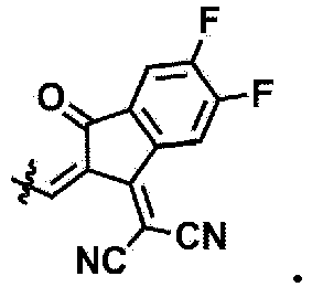
- Ra and Rb are each c is 2, and R13 is a halogen group.
- Ra and Rb are each c is 2, and R13 is fluorine.
- Ra and Rb are each
- Ra and Rb are each
- Ra and Rb are each and R10 is an alkyl group having 1 to 10 carbon atoms.
- Ra and Rb are each
- Ra and Rb are each
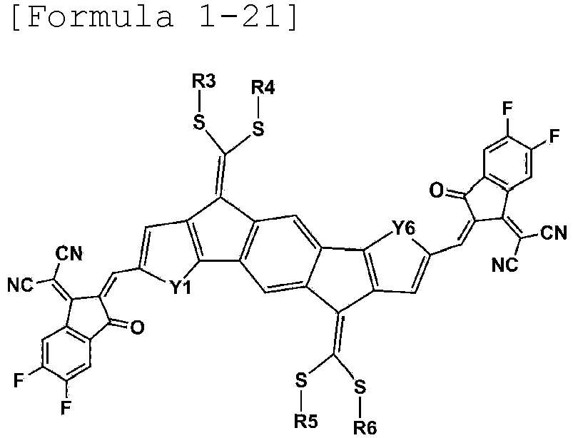
- Formula 1 may be represented by any one of the following Formulae 1-12, 1-13, 1-15, 1-16, 1-18, 1-19, 1-21 to 1-22: wherein Y1 to Y6 and R3 to R6 are as defined above.
- R3 to R6 are the same as or different from each other, and are each independently a substituted or unsubstituted alkyl group; a substituted or unsubstituted aryl group; or a substituted or unsubstituted heterocyclic group.
- R3 to R6 are the same as or different from each other, and are each independently a branched alkyl group having 1 to 20 carbon atoms.
- R3 to R6 are the same as or different from each other, and are each independently an alkyl group substituted with a substituted or unsubstituted heterocyclic group.
- R3 to R6 are the same as or different from each other, and are each independently an alkyl group substituted with a heterocyclic group substituted with an alkyl group.
- R3 to R6 are the same as or different from each other, and are each independently an alkyl group substituted with a thiophene group substituted with an alkyl group.
- R3 to R6 are the same as or different from each other, and are each independently an alkyl group substituted with a thiophene group substituted with a hexyl group.
- R3 to R6 are the same as or different from each other, and are each independently an alkyl group substituted with a substituted or unsubstituted aryl group.
- R3 to R6 are the same as or different from each other, and are each independently an alkyl group substituted with an aryl group substituted with an alkyl group.
- R3 to R6 are the same as or different from each other, and are each independently an alkyl group substituted with a phenyl group substituted with a hexyl group.
- Formula 1 may be represented by any one of the following structures.
- the photoactive layer includes the compound.
- the photoactive layer includes an electron donor material and an electron acceptor material, and the electron acceptor material includes the compound.
- the electron donor and the electron acceptor may constitute a bulk heterojunction (BHJ).
- the electron donor material and the electron acceptor material may be mixed at a ratio (w/w) of 1:10 to 10:1.
- the electron donor material and the electron acceptor material may be mixed at a ratio (w/w) of 1:1 to 1:10, and more specifically, the electron donor material and the electron acceptor material may be mixed at a ratio (w/w) of 1:1 to 1:5. If necessary, the electron donor material and the electron acceptor material may be mixed at a ratio (w/w) of 1:1 to 1:3.
- a material applied in the art may be used for the electron donor, and for example, the electron donor may include one or more materials selected from the group comprising of poly 3-hexyl thiophene (P3HT), poly[N-9'-heptadecanyl-2,7-carbazole-alt-5,5-(4'-7'-di-2-thienyl-2',1',3'-benzothiadiazole)] (PCDTBT), poly[2,6-(4,4-bis-(2-ethylhexyl)-4H-cyclopenta[2,1-b;3,4-b']dithiophene)-alt-4,7-(2,1,3-benzothiadiazole)] (PCPDTBT), poly[2,7-(9,9-dioctylfluorene)-alt-5,5-(4,7-bis(thiophene-2-yl)benzo-2,1,3-thiadiazole)] (P3HT), poly[N-9'-
- the photoactive layer may have a bilayer thin film structure including an n-type organic material layer and a p-type organic material layer.
- the organic solar cell may further include an additional organic material layer.
- the organic solar cell may reduce the number of organic material layers by using an organic material which simultaneously has various functions.
- the organic material layer includes a hole transport layer, a hole injection layer, or a layer which simultaneously transports or injects holes, and the hole transport layer, the hole injection layer, or the layer which simultaneously transports and injects holes includes the compound.
- the organic material layer includes an electron transport layer, an electron injection layer, or a layer which simultaneously transports and injects electrons, and the electron transport layer, the electron injection layer, or the layer which simultaneously transports and injects electrons includes the compound.
- the organic solar cell accepts a photon from an external light source, an electron and a hole are generated between an electron donor and an electron acceptor. The generated hole is transported to a positive electrode through an electron donor.
- an organic solar cell may be arranged in an order of a first electrode, a photoactive layer, and a second layer, and may be arranged in an order of a second electrode, a photoactive layer, and a first electrode, but the order is not limited thereto.
- the organic solar cell may be arranged in an order of a first electrode, a hole transport layer, a photoactive layer, an electron transport layer, and a second layer, and may be arranged in an order of a second electrode, an electron transport layer, a photoactive layer, a hole transport layer, and a first electrode, but the order is not limited thereto.
- the organic solar cell may further include a substrate.
- the substrate may be a glass substrate or a transparent plastic substrate having excellent transparency, surface smoothness, ease of handling, and water proof properties, but is not limited thereto, and is not limited as long as the substrate is a substrate typically used in an organic solar cell.
- Specific examples thereof include glass or polyethylene terephthalate (PET), polyethylene naphthalate (PEN), polypropylene (PP), polyimide (PI), triacetyl cellulose (TAC), and the like, but are not limited thereto.
- the organic solar cell further includes a substrate, an electron transport layer, and a hole transport layer.
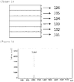
- FIG. 1 exemplifies the organic solar cell according to an exemplary embodiment of the present specification.
- FIG. 1 exemplifies the organic solar cell according to an exemplary embodiment of the present specification, in which a first electrode 102 is provided on a substrate 101, an electron transport layer 103 is provided on the first electrode 102, a photoactive layer 104 is provided on the electron transport layer 103, a hole transport layer 105 is provided on the photoactive layer 104, and a second electrode 106 is provided on the hole transport layer 105.
- a method of forming the first electrode is not particularly limited, but the first electrode may be formed, for example, by being applied onto one surface of a substrate or by being coated in the form of a film by using a method such as sputtering, e-beam, thermal deposition, spin coating, screen printing, inkjet printing, doctor blade, or gravure printing.
- the first electrode when the first electrode is formed on a substrate, the first electrode may be subjected to processes of cleaning, removing moisture, and hydrophilic modification.
- a patterned ITO substrate is sequentially cleaned with a cleaning agent, acetone, and isopropyl alcohol (IPA), and then dried on a hot plate at 100 to 150°C for 1 to 30 minutes, preferably at 120°C for 10 minutes in order to remove moisture, and when the substrate is completely cleaned, the surface of the substrate is hydrophilically modified.
- a cleaning agent acetone, and isopropyl alcohol (IPA)
- IPA isopropyl alcohol
- the junction surface potential may be maintained at a level suitable for a surface potential of a photoactive layer. Further, during the modification, a polymer thin film may be easily formed on a first electrode, and the quality of the thin film may also be improved.
- examples of a pre-treatment technology for a first electrode include a) a surface oxidation method using a parallel plate-type discharge, b) a method of oxidizing the surface through ozone produced by using UV (ultraviolet) rays in a vacuum state, c) an oxidation method using oxygen radicals produced by plasma, and the like.
- one of the methods may be selected depending on the state of the first electrode or the substrate. However, commonly in all the methods, it is preferred to prevent oxygen from being separated from the surface of the first electrode or the substrate, and maximally inhibit moisture and organic materials from remaining. In this case, it is possible to maximize a substantial effect of the pre-treatment.
- a method of oxidizing the surface through ozone produced by using UV it is possible to use a method of oxidizing the surface through ozone produced by using UV.
- a patterned ITO substrate after being ultrasonically cleaned is baked on a hot plate and dried well, and then introduced into a chamber, and the patterned ITO substrate may be cleaned by ozone generated by reacting an oxygen gas with UV light by operating a UV lamp.
- the surface modification method of the patterned ITO substrate in the present specification needs not be particularly limited, and any method may be used as long as the method is a method of oxidizing a substrate.
- the second electrode may be a metal having a low work function.
- the second electrode include: a metal such as magnesium, calcium, sodium, potassium, titanium, indium, yttrium, lithium, gadolinium, aluminum, silver, tin, and lead, or an alloy thereof; and a multi-layer structured material such as LiF/Al, LiO 2 /Al, LiF/Fe, Al:Li, Al:BaF 2 , and Al:BaF 2 :Ba, but are not limited thereto.
- the second electrode may be deposited and formed in a thermal evaporator showing a vacuum degree of 6.7 x 10 -5 Pa (5 x 10 -7 torr) or less, but the forming method is not limited to this method.
- the hole transport layer and/or electron transport layer materials serve to efficiently transfer electrons and holes separated from a photoactive layer to an electrode, and the materials are not particularly limited.
- the hole transport layer material may be poly(3,4-ethylenediocythiophene) doped with poly(styrenesulfonic acid) (PEDOT:PSS); molybdenum oxide (MoO x ); vanadium oxide (V 2 O 5 ); nickel oxide (NiO); and tungsten oxide (WO x ), and the like, but is not limited thereto.
- PEDOT:PSS poly(styrenesulfonic acid)
- MoO x molybdenum oxide
- V 2 O 5 vanadium oxide
- NiO nickel oxide
- WO x tungsten oxide
- the electron transport layer material may be electron-extracting metal oxides, and specific examples thereof include: a metal complex of 8-hydroxyquinoline; a complex including tris(8-hydroxyquinolinato)aluminum) (Alq 3 ); a metal complex including Liq; LiF; Ca; titanium oxide (TiO x ); zinc oxide (ZnO); and cesium carbonate (CS 2 CO 3 ), and the like, but are not limited thereto.
- the photoactive layer may be formed by dissolving a photoactive material such as an electron donor and/or an electron acceptor in an organic solvent, and then applying the solution by a method such as spin coating, dip coating, screen printing, spray coating, doctor blade, and brush painting, but the forming method is not limited thereto.
- a photoactive material such as an electron donor and/or an electron acceptor in an organic solvent
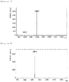
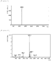
- FIG. 2 is a view illustrating an MS spectrum of Compound A-2.
- FIG. 3 is a view illustrating an MS spectrum of Compound 1.
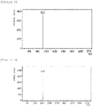
- FIG. 4 is a view illustrating an MS spectrum of Compound B-2.
- FIG. 5 is a view illustrating an MS spectrum of Compound B-3.
- FIG. 6 is a view illustrating an MS spectrum of Compound 2.
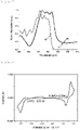
- FIG. 7 is a view illustrating a UV spectrum of Compound 3.
- (a) is UV data in which Compound 3 in a solution state was measured
- (b) is UV data in which Compound 3 in a film state was measured
- (c) is UV data in which Compound 3 was measured after being subjected to heat treatment at 110°C for 10 minutes in a film state.
- the solution state is a state in which Compound 3 is dissolved in a chlorobenzene solution, and the film was formed from Compound 3 in a solution state by a spin-coating method.
- FIG. 8 is a view illustrating a measurement result of CV of Compound 3.
- FIG. 9 is a view illustrating an MS spectrum of Compound 3.
- FIG. 10 is a view illustrating a measurement result of MALDI-TOF of Compound B-7.
- FIG. 11 is a view illustrating color changes of Compound 1 and Compound ITIC over time. Specifically, FIG. 11 illustrates the changes in color right after the solutions were dropped ( FIG.11(1) ), after one day passed ( FIG. 11(2) ), after 5 days passed ( FIG. 11(3) ), after 7 days passed ( FIG. 11(4) ), after 8 days passed ( FIG. 11(5) ), after 11 days passed ( FIG.11(6) ), after 14 days passed ( FIG. 11(7) ), after 25 days passed ( FIG. 11(8) ), and after 29 days passed ( FIG. 11(9) ).
- the composite solution of Compound 2 and Compound E was filtered by a 0.45 ⁇ m PP syringe filter, and then a photoactive layer was formed by spin-coating the solution.
- MoO 3 was deposited to have a thickness of 5 nm to 20 nm at a rate of 0.4 ⁇ /s onto the photoactive layer in a thermal evaporator, thereby manufacturing a hole transport layer.
- Ag was deposited to have a thickness of 10 nm at a rate of 1 ⁇ /s onto the hole transport layer in the thermal evaporator, thereby manufacturing an organic solar cell.
- the photoelectric conversion characteristics of the organic solar cell manufactured in Experimental Example 2-1 were measured under the condition of 100 mW/cm 2 (AM 1.5), and the results are shown in FIG. 12 .
- V oc , J sc , FF, and PCE mean an open-circuit voltage, a short-circuit current, a fill factor, and energy conversion efficiency, respectively.
- the open-circuit voltage and the short-circuit current are an X axis intercept and a Y axis intercept, respectively, in the fourth quadrant of the voltage-current density curve, and as the two values are increased, the efficiency of the solar cell is preferably increased.
- the fill factor is a value obtained by dividing the area of a rectangle, which may be drawn within the curve, by the product of the short-circuit current and the open-circuit voltage. The energy conversion efficiency may be obtained when these three values are divided by the intensity of the irradiated light, and the higher value is preferred.
Landscapes
- Chemical & Material Sciences (AREA)
- Organic Chemistry (AREA)
- Physics & Mathematics (AREA)
- Engineering & Computer Science (AREA)
- Materials Engineering (AREA)
- Spectroscopy & Molecular Physics (AREA)
- Electromagnetism (AREA)
- Photovoltaic Devices (AREA)
Description
- The present specification relates to a compound and an organic solar cell including the same.
- An organic solar cell is a device which may directly convert solar energy into electric energy by applying a photovoltaic effect. A solar cell may be divided into an inorganic solar cell and an organic solar cell, depending on the materials constituting a thin film. Typical solar cells are made through a p-n junction by doping crystalline silicon (Si), which is an inorganic semiconductor. Electrons and holes generated by absorbing light diffuse to p-n junction points and move to an electrode while being accelerated by the electric field. The power conversion efficiency in this process is defined as the ratio of electric power given to an external circuit and solar power entering the solar cell, and the efficiency have reached approximately 24% when measured under a currently standardized virtual solar irradiation condition. However, since inorganic solar cells in the related art have already shown the limitation in economic feasibility and material demands and supplies, an organic semiconductor solar cell, which is easily processed and inexpensive and has various functionalities, has come into the spotlight as a long-term alternative energy source.
- For the solar cell, it is important to increase efficiency so as to output as much electric energy as possible from solar energy. In order to increase the efficiency of the solar cell, it is important to generate as many excitons as possible inside a semiconductor, but it is also important to pull the generated charges to the outside without loss. One of the reasons for the charge loss is the dissipation of generated electrons and holes due to recombination. Various methods have been proposed to deliver generated electrons and holes to an electrode without loss, but additional processes are required in most cases, and accordingly, manufacturing costs may be increased.
-
KR 2015 0113631 A KR 2016 0097766 A - An object of the present specification is to provide a compound and an organic solar cell including the same.
- The invention provides a compound represented by one of the following
Formulae 1, A and B:


Formula 1, - Y1 to Y6 are S;
- n and m are each an integer from 0 to 5;
- when n and m are each 2 or more, the structures in the parenthesis are the same as or different from each other;
- R1 to R6 are the same as or different from each other, and are each independently hydrogen, deuterium, a halogen group, a nitrile group, a nitro group, an imide group, an amide group, a hydroxyl group, a substituted or unsubstituted alkyl group, a substituted or unsubstituted cycloalkyl group, a substituted or unsubstituted alkoxy group, a substituted or unsubstituted aryloxy group, a substituted or unsubstituted alkylthioxy group, a substituted or unsubstituted arylthioxy group, a substituted or unsubstituted alkylsulfoxy group, a substituted or unsubstituted arylsulfoxy group, a substituted or unsubstituted alkenyl group, a substituted or unsubstituted silyl group, a substituted or unsubstituted boron group, a substituted or unsubstituted alkylamine group, a substituted or unsubstituted aralkylamine group, a substituted or unsubstituted arylamine group, a substituted or unsubstituted heteroarylamine group, a substituted or unsubstituted aryl group, or a substituted or unsubstituted heterocyclic group; and
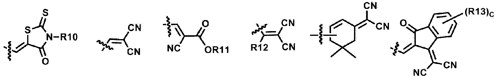
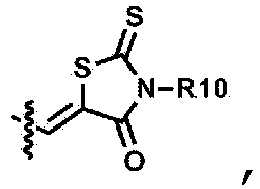
- Ra and Rb are the same as or different from each other, and are each independently an electron withdrawing group selected from the following:

- c is an integer from 1 to 4;
- when c is 2 or more, the structures in the parenthesis are the same as or different from each other; and
- R10 to R13 are the same as or different from each other, and are each independently hydrogen, deuterium, a halogen group, a nitrile group, a nitro group, an imide group, an amide group, a hydroxyl group, a substituted or unsubstituted alkyl group, a substituted or unsubstituted cycloalkyl group, a substituted or unsubstituted alkoxy group, a substituted or unsubstituted aryloxy group, a substituted or unsubstituted alkylthioxy group, a substituted or unsubstituted arylthioxy group, a substituted or unsubstituted alkylsulfoxy group, a substituted or unsubstituted arylsulfoxy group, a substituted or unsubstituted alkenyl group, a substituted or unsubstituted silyl group, a substituted or unsubstituted boron group, a substituted or unsubstituted alkylamine group, a substituted or unsubstituted aralkylamine group, a substituted or unsubstituted arylamine group, a substituted or unsubstituted heteroarylamine group, a substituted or unsubstituted aryl group, or a substituted or unsubstituted heterocyclic group;
- wherein the term "substituted or unsubstituted" means having no substituent or substituted with one or more substituents selected from deuterium, a halogen group, a nitrile group, a nitro group, an imide group, an amide group; a carbonyl group, an ester group, a hydroxyl group, an alkyl group, a cycloalkyl group, an alkoxy group, an aryloxy group, an alkylthioxy group, an arylthioxy group, an alkylsulfoxy group, an arylsulfoxy group, an alkenyl group, a silyl group, a siloxane group, a boron group, an amine group, an arylphosphine group, a phosphine oxide group, an aryl group, and a heterocyclic group, or being substituted with a substituent in which two or more of the aforementioned substituents are linked.
- The invention also provides an organic solar cell comprising:
- a first electrode;
- a second electrode provided to face the first electrode; and
- one or more organic material layers provided between the first electrode and the second electrode and comprising a photoactive layer;
- wherein one or more of the organic material layers comprise a compound as defined above.
- In the compound of the invention, sulfur (S) may be introduced into an alkyl chain. Accordingly, crystallinity due to the chalcogen-chalcogen interaction in the molecule may be improved.
- The compound according to the invention is an electron acceptor material, and may be used as a material for an organic material layer alone without fullerenes, and an organic solar cell including the same may exhibit characteristics which are excellent in an increase in opencircuit voltage and short-circuit current and/or an increase in efficiency, and the like.
- The compound has excellent oxidation stability and thus has an excellent service life when applied to a device.
-
-
FIG. 1 is a view illustrating an organic solar cell according to an exemplary embodiment of the present specification. -
FIG. 2 is a view illustrating an MS spectrum of Compound A-2. -
FIG. 3 is a view illustrating an MS spectrum ofCompound 1. -
FIG. 4 is a view illustrating an MS spectrum of Compound B-2. -
FIG. 5 is a view illustrating an MS spectrum of Compound B-3. -
FIG. 6 is a view illustrating an MS spectrum ofCompound 2. -
FIG. 7 is a view illustrating a UV spectrum ofCompound 3. -
FIG. 8 is a view illustrating a measurement result of CV of Compound 3. -
FIG. 9 is a view illustrating an MS spectrum ofCompound 3. -
FIG. 10 is a view illustrating a measurement result of MALDI-TOF of Compound B-7. -
FIG. 11 is a view illustrating color changes of Compound 1 and Compound ITIC over time. -
FIG. 12 is a view illustrating a voltage-current curve of an organic solar cell manufactured in Experimental Example 2-1.- 101: Substrate
- 102: First electrode
- 103: Electron transport layer
- 104: Photoactive layer
- 105: Hole transport layer
- 106: Second electrode
- Hereinafter, the present specification will be described in detail.
- When one part "includes" one constituent element in the present specification, unless otherwise specifically described, this does not mean that another constituent element is excluded, but means that another constituent element may be further included.
- When one member is disposed "on" another member in the present specification, this includes not only a case where the one member is brought into contact with another member, but also a case where still another member is present between the two members.
- In the present specification, the term "substituted or unsubstituted" means being substituted with one or two or more substituents selected from the group consisting of deuterium; a halogen group; a nitrile group; a nitro group; an imide group; an amide group; a carbonyl group; an ester group; a hydroxyl group; an alkyl group; a cycloalkyl group; an alkoxy group; an aryloxy group; an alkylthioxy group; an arylthioxy group; an alkylsulfoxy group; an arylsulfoxy group; an alkenyl group; a silyl group; a siloxane group; a boron group; an amine group; an arylphosphine group; a phosphine oxide group; an aryl group; and a heterocyclic group, or being substituted with a substituent to which two or more substituents among the exemplified substituents are linked or having no substituent. For example, "the substituent to which two or more substituents are linked" may be a biphenyl group. That is, the biphenyl group may also be an aryl group, and may be interpreted as a substituent to which two phenyl groups are linked.
- In the present specification,means a moiety bonded to another substituent or a bonding portion.

- In the present specification, a halogen group may be fluorine, chlorine, bromine or iodine.
- In the present specification, the number of carbon atoms of an imide group is not particularly limited, but is preferably 1 to 30. Specifically, the imide group may be a compound having the following structures, but is not limited thereto.

- In the present specification, for an amide group, the nitrogen of the amide group may be substituted with hydrogen, an alkyl group having 1 to 30 carbon atoms, or an aryl group having 6 to 30 carbon atoms. Specifically, the amide group may be a compound having the following structural formulae, but is not limited thereto.

- In the present specification, the number of carbon atoms of a carbonyl group is not particularly limited, but is preferably 1 to 30. Specifically, the carbonyl group may be a compound having the following structures, but is not limited thereto.

- In the present specification, for an ester group, the oxygen of the ester group may be substituted with an alkyl group having 1 to 25 carbon atoms, a cycloalkyl group having 3 to 30 carbon atoms, or an aryl group having 6 to 30 carbon atoms. Specifically, the ester group may be a compound having the following structural formulae, but is not limited thereto.


- In the present specification, the alkyl group may be straight-chained or branched, and the number of carbon atoms thereof is not particularly limited, but is preferably 1 to 30. Specific examples thereof include methyl, ethyl, propyl, n-propyl, isopropyl, butyl, n-butyl, isobutyl, tert-butyl, sec-butyl, 1-methyl-butyl, 1-ethylbutyl, pentyl, n-pentyl, isopentyl, neopentyl, tert-pentyl, hexyl, n-hexyl, 1-methylpentyl, 4-methyl-2-pentyl, 3,3-dimethylbutyl, 2-ethylbutyl, heptyl, n-heptyl, 1-methylhexyl, cyclopentylmethyl, cyclohexylmethyl, octyl, n-octyl, tert-octyl, 1-methylheptyl, 2-ethylhexyl, 2-propylpentyl, n-nonyl, 2,2-dimethylheptyl, 1-ethyl-propyl, 1,1-dimethyl-propyl, isohexyl, 2-methylpentyl, 4-methylhexyl, 5-methylhexyl, and the like, but are not limited thereto.
- In the present specification, a cycloalkyl group is not particularly limited, but has preferably 3 to 30 carbon atoms, and specific examples thereof include cyclopropyl, cyclobutyl, cyclopentyl, 3-methylcyclopentyl, 2,3-dimethylcyclopentyl, cyclohexyl, 3-methylcyclohexyl, 4-methylcyclohexyl, 2,3-dimethylcyclohexyl, 3,4,5-trimethylcyclohexyl, 4-tert-butylcyclohexyl, cycloheptyl, cyclooctyl, and the like, but are not limited thereto.
- In the present specification, an alkoxy group may be straight-chained, branched, or cyclic. The number of carbon atoms of the alkoxy group is not particularly limited, but is preferably 1 to 30. Specific examples thereof include methoxy, ethoxy, n-propoxy, isopropoxy, i-propyloxy, n-butoxy, isobutoxy, tert-butoxy, sec-butoxy, n-pentyloxy, neopentyloxy, isopentyloxy, n-hexyloxy, 3,3-dimethylbutyloxy, 2-ethylbutyloxy, n-octyloxy, n-nonyloxy, n-decyloxy, benzyloxy, p-methylbenzyloxy, and the like, but are not limited thereto.
- In the present specification, an amine group may be selected from the group consisting of -NH2; an alkylamine group; an N-arylalkylamine group; an arylamine group; an N-arylheteroarylamine group; an N-alkylheteroarylamine group; and a heteroarylamine group, and the number of carbon atoms thereof is not particularly limited, but is preferably 1 to 30. Specific examples of the amine group include a methylamine group, a dimethylamine group, an ethylamine group, a diethylamine group, a phenylamine group, a naphthylamine group, a biphenylamine group, an anthracenylamine group, a 9-methyl-anthracenylamine group, a diphenylamine group, an N-phenylnaphthylamine group, a ditolylamine group, an N-phenyltolylamine group, a triphenylamine group, and the like, but are not limited thereto.
- In the present specification, the alkyl group in the alkylamine group, the N-arylalkylamine group, the alkylthioxy group, the alkylsulfoxy group, and the N-alkylheteroarylamine group is the same as the above-described examples of the alkyl group.
- In the present specification, the alkenyl group may be straight-chained or branched, and the number of carbon atoms thereof is not particularly limited, but is preferably 2 to 30. Specific examples thereof include vinyl, 1-propenyl, isopropenyl, 1-butenyl, 2-butenyl, 3-butenyl, 1-pentenyl, 2-pentenyl, 3-pentenyl, 3-methyl-1-butenyl, 1,3-butadienyl, allyl, 1-phenylvinyl-1-yl, 2-phenylvinyl-1-yl, 2,2-diphenylvinyl-1-yl, 2-phenyl-2-(naphthyl-1-yl)vinyl-1-yl, 2,2-bis(diphenyl-1-yl)vinyl-1-yl, a stilbenyl group, a styrenyl group, and the like, but are not limited thereto.
- In the present specification, specific examples of a silyl group include a trimethylsilyl group, a triethylsilyl group, a t-butyldimethylsilyl group, a vinyldimethylsilyl group, a propyldimethylsilyl group, a triphenylsilyl group, a diphenylsilyl group, a phenylsilyl group, and the like, but are not limited thereto.
- In the present specification, a boron group may be - BR100R200, and R100 and R200 are the same as or different from each other, and may be each independently selected from the group consisting of hydrogen; deuterium; halogen; a nitrile group; a substituted or unsubstituted monocyclic or polycyclic cycloalkyl group having 3 to 30 carbon atoms; a substituted or unsubstituted straight-chained or branched alkyl group having 1 to 30 carbon atoms; a substituted or unsubstituted monocyclic or polycyclic aryl group having 6 to 30 carbon atoms; and a substituted or unsubstituted monocyclic or polycyclic heteroaryl group having 2 to 30 carbon atoms.
- In the present specification, specific examples of a phosphine oxide group include a diphenylphosphine oxide group, dinaphthylphosphine oxide, and the like, but are not limited thereto.
- In the present specification, an aryl group may be monocyclic or polycyclic.
- When the aryl group is a monocyclic aryl group, the number of carbon atoms thereof is not particularly limited, but is preferably 6 to 30. Specific examples of the monocyclic aryl group include a phenyl group, a biphenyl group, a terphenyl group, and the like, but are not limited thereto.
- When the aryl group is a polycyclic aryl group, the number of carbon atoms thereof is not particularly limited, but is preferably 10 to 30. Specific examples of the polycyclic aryl group include a naphthyl group, an anthracenyl group, a phenanthryl group, a pyrenyl group, a perylenyl group, a chrysenyl group, a fluorenyl group, and the like, but are not limited thereto.
- In the present specification, the aryl group in the aryloxy group, the arylthioxy group, the arylsulfoxy group, the N-arylalkylamine group, the N-arylheteroarylamine group, and the arylphosphine group is the same as the above-described examples of the aryl group.
- In the present specification, examples of the arylamine group include a substituted or unsubstituted monoarylamine group, a substituted or unsubstituted diarylamine group, or a substituted or unsubstituted triarylamine group. The aryl group in the arylamine group may be a monocyclic aryl group or a polycyclic aryl group. The arylamine group including two or more aryl groups may include a monocyclic aryl group, a polycyclic aryl group, or both a monocyclic aryl group and a polycyclic aryl group. For example, the aryl group in the arylamine group may be selected from the above-described examples of the aryl group.
- In the present specification, a heterocyclic group includes one or more atoms other than carbon, that is, one or more heteroatoms, and specifically, the heteroatom may include one or more atoms selected from the group consisting of O, N, Se, S, and the like. The number of carbon atoms thereof is not particularly limited, but is preferably 2 to 30, and the heterocyclic group may be monocyclic or polycyclic. Examples of the heterocyclic group include a thiophene group, a furanyl group, a pyrrole group, an imidazolyl group, a thiazolyl group, an oxazolyl group, an oxadiazolyl group, a pyridyl group, a bipyridyl group, a pyrimidyl group, a triazinyl group, a triazolyl group, an acridyl group, a pyridazinyl group, a pyrazinyl group, a quinolinyl group, a quinazolinyl group, a quinoxalinyl group, a phthalazinyl group, a pyridopyrimidyl group, a pyridopyrazinyl group, a pyrazinopyrazinyl group, an isoquinolinyl group, an indolyl group, a carbazolyl group, a benzoxazolyl group, a benzimidazolyl group, a benzothiazolyl group, a benzocarbazolyl group, a benzothiophene group, a dibenzothiophene group, a benzofuranyl group, a phenanthrolinyl group (phenanthroline), a thiazolyl group, an isoxazolyl group, an oxadiazolyl group, a thiadiazolyl group, a phenothiazinyl group, a dibenzofuranyl group, and the like, but are not limited thereto.
- In the present specification, examples of the heteroarylamine group include a substituted or unsubstituted monoheteroarylamine group, a substituted or unsubstituted diheteroarylamine group, or a substituted or unsubstituted triheteroarylamine group. The heteroarylamine group including two or more heteroaryl groups may include a monocyclic heteroaryl group, a polycyclic heteroaryl group, or both a monocyclic heteroaryl group and a polycyclic heteroaryl group. For example, the heteroaryl group in the heteroarylamine group may be selected from the above-described examples of the heteroaryl group.
- In the present specification, the heteroaryl group in the N-arylheteroarylamine group and the N-alkylheteroarylamine group is the same as the above-described examples of the heteroaryl group.
n and m are each an integer from 0 to 5. - In an exemplary embodiment of the present specification, n and m are each an integer from 0 to 4.
- In an exemplary embodiment of the present specification, n and m are each an integer from 0 to 3.
- In an exemplary embodiment of the present specification, n and m are each an integer from 0 to 2.
- In an exemplary embodiment of the present specification, n and m are each 0 or 1.
- In an exemplary embodiment of the present specification, the compound represented by
Formula 1 may be symmetric with respect to a benzene ring. - In an exemplary embodiment,
Formula 1 may be represented by the following Formula 1-1 or 1-2.

- In an exemplary embodiment of the present specification, when n and m of
Formula 1 are each 0,Formula 1 may be represented by Formula 1-1. - In an exemplary embodiment of the present specification, when n and m of
Formula 1 are each 1,Formula 1 may be represented by Formula 1-2. - Ra and Rb are any one of the following structures.
- In the structures,
- c is an integer from 1 to 4,
- when c is 2 or more, the structures in the parenthesis are the same as or different from each other, and
- R10 to R13 are the same as or different from each other, and are each independently hydrogen; deuterium; a halogen group; a nitrile group; a nitro group; an imide group; an amide group; a hydroxyl group; a substituted or unsubstituted alkyl group; a substituted or unsubstituted cycloalkyl group; a substituted or unsubstituted alkoxy group; a substituted or unsubstituted aryloxy group; a substituted or unsubstituted alkylthioxy group; a substituted or unsubstituted arylthioxy group; a substituted or unsubstituted alkylsulfoxy group; a substituted or unsubstituted arylsulfoxy group; a substituted or unsubstituted alkenyl group; a substituted or unsubstituted silyl group; a substituted or unsubstituted boron group; a substituted or unsubstituted alkylamine group; a substituted or unsubstituted aralkylamine group; a substituted or unsubstituted arylamine group; a substituted or unsubstituted heteroarylamine group; a substituted or unsubstituted aryl group; or a substituted or unsubstituted heterocyclic group.
- In an exemplary embodiment of the present specification, R1 and R2 are the same as or different from each other, and are each independently hydrogen; a halogen group; a substituted or unsubstituted alkyl group; a substituted or unsubstituted alkoxy group; a substituted or unsubstituted aryl group; or a substituted or unsubstituted heterocyclic group.
- In an exemplary embodiment of the present specification, R1 and R2 are hydrogen.
- In an exemplary embodiment of the present specification, R10 to R13 are the same as or different from each other, and are each independently hydrogen; a halogen group; a nitrile group; an amide group; a hydroxyl group; a substituted or unsubstituted alkyl group; a substituted or unsubstituted cycloalkyl group; a substituted or unsubstituted alkoxy group; a substituted or unsubstituted aryl group; or a substituted or unsubstituted heterocyclic group.
- In an exemplary embodiment of the present specification, R10 to R13 are the same as or different from each other, and are each independently hydrogen; a halogen group; a substituted or unsubstituted alkyl group; a substituted or unsubstituted aryl group; or a substituted or unsubstituted heterocyclic group.
- In an exemplary embodiment of the present specification, R10 and R13 are the same as or different from each other, and are each independently hydrogen; a halogen group; or a substituted or unsubstituted alkyl group.
- In an exemplary embodiment of the present specification, R10 is a substituted or unsubstituted alkyl group.
- In an exemplary embodiment of the present specification, R10 is a substituted or unsubstituted alkyl group having 1 to 30 carbon atoms.
- In an exemplary embodiment of the present specification, R10 is a substituted or unsubstituted alkyl group having 1 to 20 carbon atoms.
- In an exemplary embodiment of the present specification, R10 is a substituted or unsubstituted alkyl group having 1 to 10 carbon atoms.
- In an exemplary embodiment of the present specification, R10 is an alkyl group having 1 to 10 carbon atoms.
- In an exemplary embodiment of the present specification, R13 is hydrogen or a halogen group.
- In an exemplary embodiment of the present specification, R13 is hydrogen or fluorine.
- In an exemplary embodiment of the present specification, Ra and Rb are each

- In an exemplary embodiment of the present specification, Ra and Rb are each

- In an exemplary embodiment of the present specification, Ra and Rb are each

- In an exemplary embodiment of the present specification, Ra and Rb are each

- In an exemplary embodiment of the present specification, Ra and Rb are each
- In an exemplary embodiment of the present specification, Ra and Rb are each
- In an exemplary embodiment of the present specification, Ra and Rb are each

- In an exemplary embodiment of the present specification, Ra and Rb are each

- In an exemplary embodiment of the present specification,
Formula 1 may be represented by any one of the following Formulae 1-12, 1-13, 1-15, 1-16, 1-18, 1-19, 1-21 to 1-22: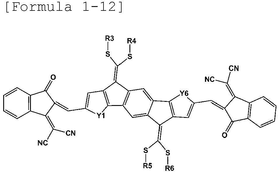


- In an exemplary embodiment of the present specification, R3 to R6 are the same as or different from each other, and are each independently a substituted or unsubstituted alkyl group; a substituted or unsubstituted aryl group; or a substituted or unsubstituted heterocyclic group.
- In an exemplary embodiment of the present specification, R3 to R6 are the same as or different from each other, and are each independently a branched alkyl group having 1 to 20 carbon atoms.
- In an exemplary embodiment of the present specification, R3 to R6 are the same as or different from each other, and are each independently an alkyl group substituted with a substituted or unsubstituted heterocyclic group.
- In an exemplary embodiment of the present specification, R3 to R6 are the same as or different from each other, and are each independently an alkyl group substituted with a heterocyclic group substituted with an alkyl group.
- In an exemplary embodiment of the present specification, R3 to R6 are the same as or different from each other, and are each independently an alkyl group substituted with a thiophene group substituted with an alkyl group.
- In an exemplary embodiment of the present specification, R3 to R6 are the same as or different from each other, and are each independently an alkyl group substituted with a thiophene group substituted with a hexyl group.
- In an exemplary embodiment of the present specification, R3 to R6 are the same as or different from each other, and are each independently an alkyl group substituted with a substituted or unsubstituted aryl group.
- In an exemplary embodiment of the present specification, R3 to R6 are the same as or different from each other, and are each independently an alkyl group substituted with an aryl group substituted with an alkyl group.
- In an exemplary embodiment of the present specification, R3 to R6 are the same as or different from each other, and are each independently an alkyl group substituted with a phenyl group substituted with an alkyl group.
- In an exemplary embodiment of the present specification, R3 to R6 are the same as or different from each other, and are each independently an alkyl group substituted with a phenyl group substituted with a hexyl group.
- In an exemplary embodiment of the present specification,
Formula 1 may be represented by any one of the following structures.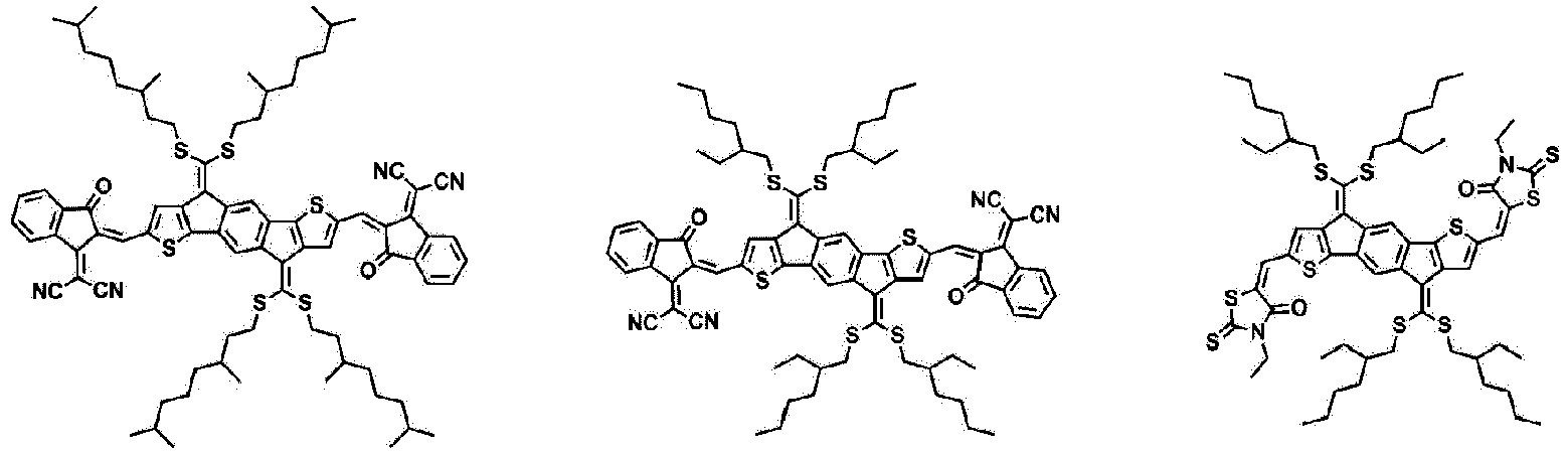


- An exemplary embodiment of the present specification provides an organic solar cell including:
- a first electrode;
- a second electrode provided to face the first electrode; and
- an organic material layer having one or more layers provided between the first electrode and the second electrode and including a photoactive layer,
- in which one or more layers of the organic material layer include the compound.
- In an exemplary embodiment of the present specification, the photoactive layer includes the compound.
- In an exemplary embodiment of the present specification, the photoactive layer includes an electron donor material and an electron acceptor material, and the electron acceptor material includes the compound.
- In an exemplary embodiment of the present specification, the electron donor and the electron acceptor may constitute a bulk heterojunction (BHJ). The electron donor material and the electron acceptor material may be mixed at a ratio (w/w) of 1:10 to 10:1. Specifically, the electron donor material and the electron acceptor material may be mixed at a ratio (w/w) of 1:1 to 1:10, and more specifically, the electron donor material and the electron acceptor material may be mixed at a ratio (w/w) of 1:1 to 1:5. If necessary, the electron donor material and the electron acceptor material may be mixed at a ratio (w/w) of 1:1 to 1:3.
- In an exemplary embodiment of the present specification, a material applied in the art may be used for the electron donor, and for example, the electron donor may include one or more materials selected from the group comprising of poly 3-hexyl thiophene (P3HT), poly[N-9'-heptadecanyl-2,7-carbazole-alt-5,5-(4'-7'-di-2-thienyl-2',1',3'-benzothiadiazole)] (PCDTBT), poly[2,6-(4,4-bis-(2-ethylhexyl)-4H-cyclopenta[2,1-b;3,4-b']dithiophene)-alt-4,7-(2,1,3-benzothiadiazole)] (PCPDTBT), poly[2,7-(9,9-dioctylfluorene)-alt-5,5-(4,7-bis(thiophene-2-yl)benzo-2,1,3-thiadiazole)] (PFO-DBT), poly[[4,8-bis[(2-ethylhexyl)oxy]benzo[1,2-b:4,5-b']dithiophene-2,6-diyl][3-fluoro-2-[(2-ethylhexyl)carbonyl]thieno[3,4-b]thiophenediyl]] (PTB7), poly[2,7-(9,9-dioctyl-dibenzosilole)-alt-4,7-bis(thiophen-2-yl)benzo-2,1,3-thiadiazole] (PSiF-DBT), poly[4,8-bis(5-(2-ethylhexyl)thiophen-2-yl)benzo[1,2-b;4,5-b']dithiophene-2,6-diyl-alt-(4-(2-ethylhexyl)-3-fluorothieno[3,4-b]thiophene-)-2-carboxylate-2-6-diyl)] (PTB7-Th), and poly(benzodithiophene-benzotriazole (PBDBT).
- In an exemplary embodiment of the present specification, the photoactive layer may have a bilayer thin film structure including an n-type organic material layer and a p-type organic material layer.
- In the present specification, the organic solar cell may further include an additional organic material layer. The organic solar cell may reduce the number of organic material layers by using an organic material which simultaneously has various functions.
- In an exemplary embodiment of the present specification, the organic material layer includes a hole transport layer, a hole injection layer, or a layer which simultaneously transports or injects holes, and the hole transport layer, the hole injection layer, or the layer which simultaneously transports and injects holes includes the compound.
- In an exemplary embodiment of the present specification, the organic material layer includes an electron transport layer, an electron injection layer, or a layer which simultaneously transports and injects electrons, and the electron transport layer, the electron injection layer, or the layer which simultaneously transports and injects electrons includes the compound.
- In the present specification, when the organic solar cell accepts a photon from an external light source, an electron and a hole are generated between an electron donor and an electron acceptor. The generated hole is transported to a positive electrode through an electron donor.
- In an exemplary embodiment of the present specification, an organic solar cell may be arranged in an order of a first electrode, a photoactive layer, and a second layer, and may be arranged in an order of a second electrode, a photoactive layer, and a first electrode, but the order is not limited thereto.
- In an exemplary embodiment of the present specification, the organic solar cell may be arranged in an order of a first electrode, a hole transport layer, a photoactive layer, an electron transport layer, and a second layer, and may be arranged in an order of a second electrode, an electron transport layer, a photoactive layer, a hole transport layer, and a first electrode, but the order is not limited thereto.
- In an exemplary embodiment of the present specification, the organic solar cell may further include a substrate.
- In an exemplary embodiment of the present specification, the substrate may be a glass substrate or a transparent plastic substrate having excellent transparency, surface smoothness, ease of handling, and water proof properties, but is not limited thereto, and is not limited as long as the substrate is a substrate typically used in an organic solar cell. Specific examples thereof include glass or polyethylene terephthalate (PET), polyethylene naphthalate (PEN), polypropylene (PP), polyimide (PI), triacetyl cellulose (TAC), and the like, but are not limited thereto.
- In an exemplary embodiment of the present specification, the organic solar cell further includes a substrate, an electron transport layer, and a hole transport layer.
-
FIG. 1 exemplifies the organic solar cell according to an exemplary embodiment of the present specification. Specifically,FIG. 1 exemplifies the organic solar cell according to an exemplary embodiment of the present specification, in which afirst electrode 102 is provided on asubstrate 101, anelectron transport layer 103 is provided on thefirst electrode 102, aphotoactive layer 104 is provided on theelectron transport layer 103, ahole transport layer 105 is provided on thephotoactive layer 104, and asecond electrode 106 is provided on thehole transport layer 105. - In an exemplary embodiment of the present specification, the first electrode may be made of a material which is transparent and has excellent conductivity. Examples of the first electrode include: a metal such as vanadium, chromium, copper, zinc, and gold, or an alloy thereof; a metal oxide such as zinc oxide, indium oxide, indium tin oxide (ITO), and indium zinc oxide (IZO); a combination of a metal and an oxide, such as ZnO:Al or SnO2:Sb; a conductive polymer such as poly(3-methylthiophene), poly[3,4-(ethylene-1,2-dioxy)thiophene] (PEDOT), polypyrrole, and polyaniline; and the like, but are not limited thereto.
- In an exemplary embodiment of the present specification, a method of forming the first electrode is not particularly limited, but the first electrode may be formed, for example, by being applied onto one surface of a substrate or by being coated in the form of a film by using a method such as sputtering, e-beam, thermal deposition, spin coating, screen printing, inkjet printing, doctor blade, or gravure printing.
- In an exemplary embodiment of the present specification, when the first electrode is formed on a substrate, the first electrode may be subjected to processes of cleaning, removing moisture, and hydrophilic modification.
- For example, a patterned ITO substrate is sequentially cleaned with a cleaning agent, acetone, and isopropyl alcohol (IPA), and then dried on a hot plate at 100 to 150°C for 1 to 30 minutes, preferably at 120°C for 10 minutes in order to remove moisture, and when the substrate is completely cleaned, the surface of the substrate is hydrophilically modified.
- Through the surface modification as described above, the junction surface potential may be maintained at a level suitable for a surface potential of a photoactive layer. Further, during the modification, a polymer thin film may be easily formed on a first electrode, and the quality of the thin film may also be improved.
- In the present specification, examples of a pre-treatment technology for a first electrode include a) a surface oxidation method using a parallel plate-type discharge, b) a method of oxidizing the surface through ozone produced by using UV (ultraviolet) rays in a vacuum state, c) an oxidation method using oxygen radicals produced by plasma, and the like.
- In an exemplary embodiment of the present specification, one of the methods may be selected depending on the state of the first electrode or the substrate. However, commonly in all the methods, it is preferred to prevent oxygen from being separated from the surface of the first electrode or the substrate, and maximally inhibit moisture and organic materials from remaining. In this case, it is possible to maximize a substantial effect of the pre-treatment.
- As a specific example, it is possible to use a method of oxidizing the surface through ozone produced by using UV. In this case, a patterned ITO substrate after being ultrasonically cleaned is baked on a hot plate and dried well, and then introduced into a chamber, and the patterned ITO substrate may be cleaned by ozone generated by reacting an oxygen gas with UV light by operating a UV lamp.
- However, the surface modification method of the patterned ITO substrate in the present specification needs not be particularly limited, and any method may be used as long as the method is a method of oxidizing a substrate.
- In an exemplary embodiment of the present specification, the second electrode may be a metal having a low work function. Specific examples of the second electrode include: a metal such as magnesium, calcium, sodium, potassium, titanium, indium, yttrium, lithium, gadolinium, aluminum, silver, tin, and lead, or an alloy thereof; and a multi-layer structured material such as LiF/Al, LiO2/Al, LiF/Fe, Al:Li, Al:BaF2, and Al:BaF2:Ba, but are not limited thereto.
- In an exemplary embodiment of the present specification, the second electrode may be deposited and formed in a thermal evaporator showing a vacuum degree of 6.7 x 10⁻⁵ Pa (5 x 10⁻⁷ torr) or less, but the forming method is not limited to this method.
- In an exemplary embodiment of the present specification, the hole transport layer and/or electron transport layer materials serve to efficiently transfer electrons and holes separated from a photoactive layer to an electrode, and the materials are not particularly limited.
- In an exemplary embodiment of the present specification, the hole transport layer material may be poly(3,4-ethylenediocythiophene) doped with poly(styrenesulfonic acid) (PEDOT:PSS); molybdenum oxide (MoOx); vanadium oxide (V2O5); nickel oxide (NiO); and tungsten oxide (WOx), and the like, but is not limited thereto.
- In an exemplary embodiment of the present specification, the electron transport layer material may be electron-extracting metal oxides, and specific examples thereof include: a metal complex of 8-hydroxyquinoline; a complex including tris(8-hydroxyquinolinato)aluminum) (Alq3); a metal complex including Liq; LiF; Ca; titanium oxide (TiOx); zinc oxide (ZnO); and cesium carbonate (CS2CO3), and the like, but are not limited thereto.
- In an exemplary embodiment of the present specification, the photoactive layer may be formed by dissolving a photoactive material such as an electron donor and/or an electron acceptor in an organic solvent, and then applying the solution by a method such as spin coating, dip coating, screen printing, spray coating, doctor blade, and brush painting, but the forming method is not limited thereto.
- In the present specification, a preparation method of the compound and the manufacture of an organic solar cell including the same will be described in detail in the following Preparation Examples and Examples. However, the following Examples are provided for exemplifying the present specification, and the scope of the present specification is not limited thereby.
-

- 1.49 mL of phosphorus oxychloride (POCl3) (16 mmol) was added to 1.55 mL of N,N-dimethylformamide (DMF) (20 mmol), and the resulting mixture was stirred at 0°C for 60 minutes to prepare a mixed solution. A solution, in which Compound A-1 (1.53 mmol) was dissolved in 20 mL of dichloroethane (DCE), was added to the prepared mixed solution, and the resulting mixture was stirred at 100°C for 48 hours. After the stirring, 1 M of sodium hydroxide (NaOH) was added thereto, and the resulting mixture was stirred for 1 hour for neutralization. Thereafter, the product was extracted with dichloromethane, and the extract was dried over anhydrous MgSO4 and evaporated. After the solvent was removed under reduced pressure, the residue was purified through flash chromatography (hexane : chloroform = 4 : 1) using hexane and chloroform as an eluent to obtain 1.066 g of Compound A-2. (Yield: 67.3%)
-
FIG. 2 is a view illustrating an MS spectrum of Compound A-2. -

- 2 mL of pyridine was added to a solution in which Compound A-2 (0.725 g, 0.7 mmol) and Compound C-1 (0.68 g, 3.5 mmol) were mixed in 40 mL of chloroform (CHCl3) under a nitrogen (N2) atmosphere. After this mixed solution was refluxed under a nitrogen atmosphere for 24 hours, the product was extracted with dichloromethane (CH2Cl2), and washed with water. After the solvent was removed, the residue was recrystallized through methyl chloride (MC)/methanol, and the product was purified through chromatography using a silica gel column using hexane, acetone, ethyl acetate, and chloroform (CHCl3) as an eluent. The produced solid was recrystallized through chloroform. Thereafter, the solid was washed with methanol and dried under a vacuum condition to obtain 905 mg of
Compound 1. (Yield: 93%) (MALDI-TOF MS: 1,386.6 g/mol) -
FIG. 3 is a view illustrating an MS spectrum ofCompound 1. -

- After 4.13 g (43 mmol) of sodium-t-butoxide (NaOC(CH3)3) was added to 100 mL of tetrahydrofuran (THF) in which Compound B-1 (2.5 g, 9.4 mmol) was dissolved, a total of 2.58 mL of carbon disulfide (CS2) (43 mmol) was added thereto for 1 hour. Thereafter, 8.89 mL (50 mmol) of 2-ethylhexyl bromide was added thereto, and the resulting mixture was stirred for 24 hours. After the reaction, the reaction was terminated by adding ammonium hydroxide (NH4OH) thereto, and the resulting product was extracted with dichloromethane (DCM), and then washed three times with water. The product was purified through chromatography using a silica gel column using hexane as an eluent to obtain 3.63 g of Compound B-2 in the form of a red oil. (Yield: 45%)
-
FIG. 4 is a view illustrating an MS spectrum of Compound B-2. -

- 4 mL of phosphorus oxychloride (POCl3) (43 mmol) was added to N,N-dimethylformamide (DMF)(55 mmol), and the resulting mixture was stirred at 0°C for 60 minutes to prepare a mixed solution. A solution, in which Compound B-2 (4.19 mmol) was dissolved in 40 mL of dichloroethane (DCE), was added to the prepared mixed solution, and the resulting mixture was stirred at 100°C for 48 hours. After the stirring, 1 M of sodium hydroxide (NaOH) was added thereto, and the resulting mixture was stirred for 1 hour for neutralization. Thereafter, the product was extracted with dichloromethane, and the extract was dried over anhydrous MgSO4 and evaporated. After the solvent was removed under reduced pressure, the residue was purified through flash chromatography (hexane : chloroform = 4 : 1) using hexane and chloroform as an eluent to obtain 2.47 g of Compound B-3. (Yield: 64%)
-
FIG. 5 is a view illustrating an MS spectrum of Compound B-3. -
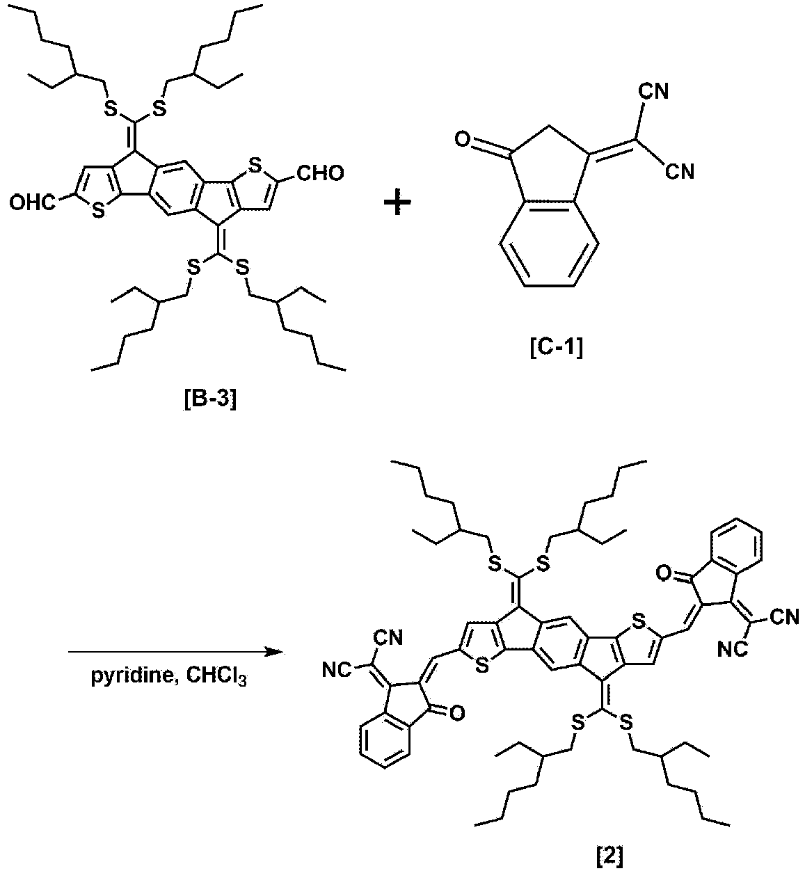
- 2 mL of pyridine was added to a solution in which Compound B-3 (0.44 g, 0.48 mmol) and Compound C-1 (0.93 g, 4.8 mmol) were mixed in 30 mL of chloroform (CHCl3) under a nitrogen (N2) atmosphere. After this mixed solution was refluxed under a nitrogen atmosphere for 24 hours, the product was extracted with dichloromethane (CH2Cl2), and washed with water. After the solvent was removed, the residue was recrystallized through methyl chloride (MC)/methanol, and the product was purified through chromatography using a silica gel column using hexane, ethyl acetate, and chloroform (CHCl3) as an eluent. The produced solid was recrystallized through chloroform. Thereafter, the product was washed with methanol and dried under a vacuum condition to obtain 550 mg of
Compound 2. (Yield: 90%) (MALDI-TOF MS: 1,274.6 g/mol) -
FIG. 6 is a view illustrating an MS spectrum ofCompound 2. -

- Three drops of piperidine were added to a solution in which Compound B-3 (0.83 g, 0.9 mmol) and Compound C-2 (1.45 g, 9 mmol) were mixed in 15 mL of chloroform (CHCl3) under a nitrogen (N2) atmosphere. After this mixed solution was refluxed under a nitrogen atmosphere for 24 hours, the product was extracted with dichloromethane (CH2Cl2), and washed with water. After the solvent was removed, the residue was recrystallized through methyl chloride (MC)/methanol, and the product was purified through chromatography using a silica gel column using hexane, ethyl acetate, and chloroform (CHCl3) as an eluent. The produced solid was recrystallized through chloroform. Thereafter, the product was washed with methanol and dried under a vacuum condition to obtain 918 mg of
Compound 3. (Yield: 84.3%) (MALDI-TOF MS: 1,208.3 g/mol) -
FIG. 7 is a view illustrating a UV spectrum ofCompound 3. - In
FIG. 7 , (a) is UV data in whichCompound 3 in a solution state was measured, (b) is UV data in whichCompound 3 in a film state was measured, and (c) is UV data in whichCompound 3 was measured after being subjected to heat treatment at 110°C for 10 minutes in a film state. - In this case, the solution state is a state in which
Compound 3 is dissolved in a chlorobenzene solution, and the film was formed fromCompound 3 in a solution state by a spin-coating method. - In
FIG. 7 , it can be confirmed that the vibronic peak (c) after the film was subjected to heat treatment was increased as compared to the vibronic peak before the film was subjected to heat treatment. Through this, it can be confirmed that after the heat treatment, the crystallinity is excellent. -
FIG. 8 is a view illustrating a measurement result of CV ofCompound 3. -
FIG. 9 is a view illustrating an MS spectrum ofCompound 3. -

- After 2.1 g (21.85 mmol) of sodium-t-butoxide (NaOC(CH3)3) was added to a solution in which Compound B-1 (1.25 g, 4.7 mmol) was dissolved in 100 mL of tetrahydrofuran (THF) and the resulting mixture was reacted for 1 hour, 1.31 mL of carbon disulfide (CS2) (21.85 mmol) was added thereto. After the reaction for 1 hour, Compound C-3 (6.53 g, 25 mmol) was added thereto, and the resulting mixture was stirred for 24 hours. After the reaction, the reaction was terminated by adding ammonium hydroxide (NH4OH) thereto, and the resulting product was extracted with dichloromethane (DCM), and then washed three times with water. The product was purified through chromatography using a silica gel column using hexane as an eluent to obtain 2.15 g of Compound B-4 in the form of a red viscous oil. (Yield: 40%) (LCQ MS: 1,140.1 g/mol)
-

- 4 mL of phosphorus oxychloride (POCl3) (43 mmol) was added to N,N-dimethylformamide (DMF)(55 mmol), and the resulting mixture was stirred at 0°C for 60 minutes to prepare a mixed solution. A solution, in which Compound B-4 (4.77 g, 4.19 mmol) was dissolved in 40 mL of dichloroethane (DCE), was added to the prepared mixed solution, and the resulting mixture was stirred at 100°C for 48 hours. After the stirring, 1 M of sodium hydroxide (NaOH) was added thereto, and the resulting mixture was stirred for 1 hour for neutralization. Thereafter, the product was extracted with dichloromethane, and the extract was dried over anhydrous MgSO4 and evaporated. After the solvent was removed under reduced pressure, the residue was purified through flash chromatography (hexane : chloroform = 4 : 1) using hexane and chloroform as an eluent to obtain 4.1 g of Compound B-5. (Yield: 82%) (MALDI-TOF MS: 1,196.2 g/mol)
-

- 2 mL of pyridine was added to a solution in which Compound B-5 (1 g, 0.84 mmol) and Compound C-1 (1.55 g, 8 mmol) were mixed in 30 mL of chloroform (CHCl3) under a nitrogen (N2) atmosphere. After this mixed solution was refluxed under a nitrogen atmosphere for 24 hours, the product was extracted with dichloromethane (CH2Cl2), and washed with water. After the solvent was removed, the residue was recrystallized through methyl chloride (MC)/methanol, and the product was purified through chromatography using a silica gel column using hexane, ethyl acetate, and chloroform (CHCl3) as an eluent. The produced solid was recrystallized through chloroform. Thereafter, the product was washed with methanol and dried under a vacuum condition to obtain 950 mg of
Compound 4. (Yield: 73%) (MALDI-TOF MS: 1,548.2 g/mol) -

- Three drops of piperidine were added to a solution in which Compound B-5 (1 g, 0.84 mmol) and Compound C-4 (1.96 g, 8 mmol) were mixed in 30 mL of chloroform (CHCl3) under a nitrogen (N2) atmosphere. After this mixed solution was refluxed under a nitrogen atmosphere for 24 hours, the product was extracted with dichloromethane (CH2Cl2), and washed with water. After the solvent was removed, the residue was recrystallized through methyl chloride (MC)/methanol, and the product was purified through chromatography using a silica gel column using hexane, ethyl acetate, and chloroform (CHCl3) as an eluent. The produced solid was recrystallized through chloroform. Thereafter, the product was washed with methanol and dried under a vacuum condition to obtain 1.04 g of
Compound 5. (Yield: 75%) (MALDI-TOF MS: 1,650.6 g/mol) -

- Three drops of piperidine were added to a solution in which Compound B-5 (1 g, 0.84 mmol) and Compound C-2 (1.29 g, 8 mmol) were mixed in 30 mL of chloroform (CHCl3) under a nitrogen (N2) atmosphere. After this mixed solution was refluxed under a nitrogen atmosphere for 24 hours, the product was extracted with dichloromethane (CH2Cl2), and washed with water. After the solvent was removed, the residue was recrystallized through methyl chloride (MC)/methanol, and the product was purified through chromatography using a silica gel column using hexane, ethyl acetate, and chloroform (CHCl3) as an eluent. The produced solid was recrystallized through chloroform. Thereafter, the product was washed with methanol and dried under a vacuum condition to obtain 860 mg of
Compound 6. (Yield: 69%) (MALDI-TOF MS: 1,482.2 g/mol) -

- After 2.1 g (21.85 mmol) of sodium-t-butoxide (NaOC(CH3)3) was added to a solution in which Compound B-1 (1.25 g, 4.7 mmol) was dissolved in 100 mL of tetrahydrofuran (THF), the resulting mixture was reacted for 1 hour. After the reaction, 1.31 mL of carbon disulfide (CS2) (21.85 mmol) was added thereto, and the resulting mixture was reacted for 1 hour. Thereafter, Compound C-5 (6.38 g, 25 mmol) was added thereto, and the resulting mixture was stirred for 24 hours. After the reaction, the reaction was terminated by adding ammonium hydroxide (NH4OH) thereto, and the resulting product was extracted with dichloromethane (DCM), and then washed three times with water. The product was purified through chromatography using a silica gel column using hexane as an eluent to obtain 2.5 g of Compound B-6 in the form of a red viscous oil. (Yield: 48%) (LCQ MS: 1,115.3 g/mol)
-
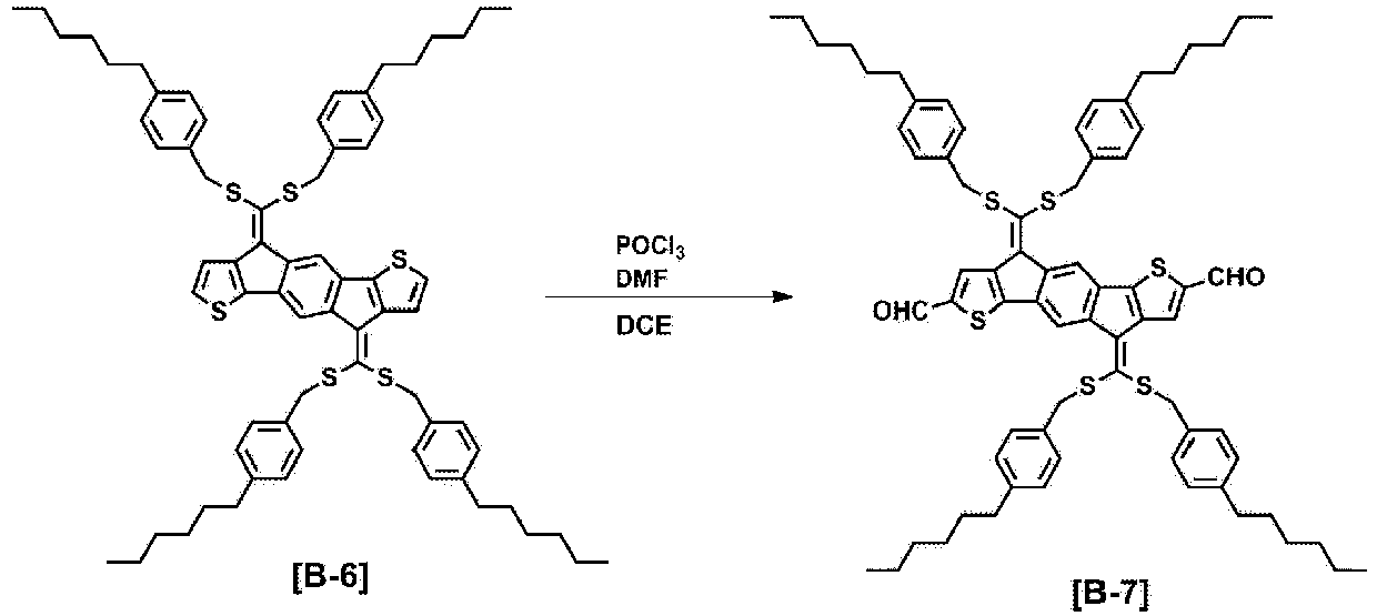
- 4 mL of phosphorus oxychloride (POCl3) (43 mmol) was added to N,N-dimethylformamide (DMF)(55 mmol), and the resulting mixture was stirred at 0°C for 60 minutes to prepare a mixed solution. A solution, in which Compound B-6 (4.67 g, 4.19 mmol) was dissolved in 40 mL of dichloroethane (DCE), was added to the prepared mixed solution, and the resulting mixture was stirred at 100°C for 48 hours. After the stirring, 1 M of sodium hydroxide (NaOH) was added thereto, and the resulting mixture was stirred for 1 hour for neutralization. Thereafter, the product was extracted with dichloromethane, and the extract was dried over anhydrous MgSO4 and evaporated. After the solvent was removed under reduced pressure, the residue was purified through flash chromatography (hexane : chloroform = 4 : 1) using hexane and chloroform as an eluent to obtain 3.5 g of Compound B-7. (Yield: 71%) (MALDI-TOF MS: 1,171.5 g/mol)
-
FIG. 10 is a view illustrating a measurement result of MALDI-TOF of Compound B-7. -

- Three drops of piperidine were added to a solution in which Compound B-7 (1 g, 0.85 mmol) and Compound C-2 (1.29 g, 8 mmol) were mixed in 30 mL of chloroform (CHCl3) under a nitrogen (N2) atmosphere. After this mixed solution was refluxed under a nitrogen atmosphere for 24 hours, the product was extracted with dichloromethane (CH2Cl2), and washed with water. After the solvent was removed, the residue was recrystallized through methyl chloride (MC)/methanol, and the product was purified through chromatography using a silica gel column using hexane, ethyl acetate, and chloroform (CHCl3) as an eluent. The produced solid was recrystallized through chloroform. Thereafter, the product was washed with methanol and dried under a vacuum condition to obtain 970 mg of
Compound 7. (Yield: 78%) (MALDI-TOF MS: 1,457.6 g/mol) -

- Three drops of piperidine were added to a solution in which Compound B-7 (1 g, 0.85 mmol) and Compound C-4 (1.96 g, 8 mmol) were mixed in 30 mL of chloroform (CHCl3) under a nitrogen (N2) atmosphere. After this mixed solution was refluxed under a nitrogen atmosphere for 24 hours, the product was extracted with dichloromethane (CH2Cl2), and washed with water. After the solvent was removed, the residue was recrystallized through methyl chloride (MC)/methanol, and the product was purified through chromatography using a silica gel column using hexane, ethyl acetate, and chloroform (CHCl3) as an eluent. The produced solid was recrystallized through chloroform. Thereafter, the product was washed with methanol and dried under a vacuum condition to obtain 1.1 g of
Compound 8. (Yield: 80%) (MALDI-TOF MS: 1,627.1 g/mol) -

- 2 mL of pyridine was added to a solution in which Compound B-7 (1 g, 0.85 mmol) and Compound C-1 (1.55 g, 8 mmol) were mixed in 30 mL of chloroform (CHCl3) under a nitrogen (N2) atmosphere. After this mixed solution was refluxed under a nitrogen atmosphere for 24 hours, the product was extracted with dichloromethane (CH2Cl2), and washed with water. After the solvent was removed, the residue was recrystallized through methyl chloride (MC)/methanol, and the product was purified through chromatography using a silica gel column using hexane, ethyl acetate, and chloroform (CHCl3) as an eluent. The produced solid was recrystallized through chloroform. Thereafter, the product was washed with methanol and dried under a vacuum condition to obtain 910 mg of
Compound 9. (Yield: 70%) (MALDI-TOF MS: 1,524.1 g/mol) -

- 2 mL of pyridine was added to a solution in which Compound B-5 (0.48 g, 0.4 mmol) and Compound C-6 (0.92 g, 4 mmol) were mixed in 30 mL of chloroform (CHCl3) under a nitrogen (N2) atmosphere. After this mixed solution was refluxed under a nitrogen atmosphere for 24 hours, the product was extracted with dichloromethane (CH2Cl2), and washed with water. After the solvent was removed, the residue was recrystallized through methyl chloride (MC)/methanol, and the product was purified through chromatography using a silica gel column using hexane, ethyl acetate, and chloroform (CHCl3) as an eluent. The produced solid was recrystallized through chloroform. Thereafter, the product was washed with methanol and dried under a vacuum condition to obtain 410 mg of Compound 10. (Yield: 64%) (MALDI-TOF MS: 1,618.5 g/mol)
-

- 2 mL of pyridine was added to a solution in which Compound B-7 (0.5 g, 0.43 mmol) and Compound C-6 (0.99 g, 4.3 mmol) were mixed in 30 mL of chloroform (CHCl3) under a nitrogen (N2) atmosphere. After this mixed solution was refluxed under a nitrogen atmosphere for 24 hours, the product was extracted with dichloromethane (CH2Cl2), and washed with water. After the solvent was removed, the residue was recrystallized through methyl chloride (MC)/methanol, and the product was purified through chromatography using a silica gel column using hexane, ethyl acetate, and chloroform (CHCl3) as an eluent. The produced solid was recrystallized through chloroform. Thereafter, the product was washed with methanol and dried under a vacuum condition to obtain 492 mg of
Compound 11. (Yield: 72%) (MALDI-TOF MS: 1,594.4 g/mol) -

- 0.56 mL of phosphorus oxychloride (POCl3) (6 mmol) was added to N,N-dimethylformamide (DMF)(0.54 mL, 7 mmol), and the resulting mixture was stirred at 0°C for 60 minutes to prepare a mixed solution. A solution, in which Compound D-1 (1.20 g, 2.51 mmol) was dissolved in 20 mL of dichloroethane (DCE), was added to the prepared mixed solution, and the resulting mixture was stirred at 100°C for 48 hours. After the stirring, 1 M of sodium hydroxide (NaOH) was added thereto, and the resulting mixture was stirred for 1 hour for neutralization. Thereafter, the product was extracted with dichloromethane, and the extract was dried over anhydrous MgSO4 and evaporated. After the solvent was removed under reduced pressure, the residue was purified through flash chromatography (hexane : chloroform = 4 : 1) using hexane and chloroform as an eluent to obtain 0.86 g of Compound D-2. (Yield: 64%) (MALDI-TOF MS: 534.2 g/mol)
-

- 2 mL of pyridine was added to a solution in which Compound D-2 (0.40 g, 0.75 mmol) and Compound C-1 (1.45 g, 7.5 mmol) were mixed in 15 mL of chloroform (CHCl3) under a nitrogen (N2) atmosphere. After this mixed solution was refluxed under a nitrogen atmosphere for 24 hours, the product was extracted with dichloromethane (CH2Cl2), and washed with water. After the solvent was removed, the residue was recrystallized through methyl chloride (MC)/methanol, and the product was purified through chromatography using a silica gel column using hexane, ethyl acetate, and chloroform (CHCl3) as an eluent. The produced solid was recrystallized through chloroform. Thereafter, the product was washed with methanol and dried under a vacuum condition to obtain 397 mg of
Compound 12. (Yield: 60%) (MALDI-TOF MS: 886.2 g/mol) -

- 2 mL of pyridine was added to a solution in which Compound D-2 (0.40 g, 0.75 mmol) and Compound C-6 (1.73g, 7.5 mmol) were mixed in 15 mL of chloroform (CHCl3) under a nitrogen (N2) atmosphere. After this mixed solution was refluxed under a nitrogen atmosphere for 24 hours, the product was extracted with dichloromethane (CH2Cl2), and washed with water. After the solvent was removed, the residue was recrystallized through methyl chloride (MC)/methanol, and the product was purified through chromatography using a silica gel column using hexane, ethyl acetate, and chloroform (CHCl3) as an eluent. The produced solid was recrystallized through chloroform. Thereafter, the solid was washed with methanol and dried under a vacuum condition to obtain 453 mg of Compound 13. (Yield: 63%) (MALDI-TOF MS: 958.3 g/mol)
-
Solution 1 in whichCompound 1 was dissolved in chloroform andSolution 2 in which the following Compound ITIC was dissolved in chloroform were each dropped on a TLC plate. Thereafter, the change in color over time was observed under the air environment.FIG. 11 is a view illustrating color changes ofCompound 1 and Compound ITIC over time. Specifically,FIG. 11 illustrates the changes in color right after the solutions were dropped (FIG.11(1) ), after one day passed (FIG. 11(2) ), after 5 days passed (FIG. 11(3) ), after 7 days passed (FIG. 11(4) ), after 8 days passed (FIG. 11(5) ), after 11 days passed (FIG.11(6) ), after 14 days passed (FIG. 11(7) ), after 25 days passed (FIG. 11(8) ), and after 29 days passed (FIG. 11(9) ). - In
FIG. 11 , (a) isSolution 1 in whichCompound 1 is dissolved, and (b) isSolution 2 in which Compound ITIC is dissolved. - According to
FIG. 11 , it can be confirmed that in the case of a solution in which Compound ITIC is dissolved (Solution 2), the change in color occurs as time elapses, whereas in the case of a solution in whichCompound 1 is dissolved (Solution 1), the change in color does not occur even though time elapses. Through this, it can be confirmed that the compound according to an exemplary embodiment of the present specification is stable.
- A composite solution was prepared by dissolving
Compound 2 prepared in Preparation Example 2 and Compound E at a ratio of 1:2 in chlorobenzene (CB). In this case, the concentration was adjusted to 2.0 wt%, and the organic solar cell was made to have a structure of ITO/ZnO/a photoactive layer/MoO3/Ag. A glass substrate coated with ITO was ultrasonically washed using distilled water, acetone, and 2-propanol, and the ITO surface was treated with ozone for 10 minutes, followed by a heat treatment at 120°C for 10 minutes by spin-coating a ZnO precursor solution. Thereafter, the composite solution ofCompound 2 and Compound E was filtered by a 0.45 µm PP syringe filter, and then a photoactive layer was formed by spin-coating the solution. Thereafter, MoO3 was deposited to have a thickness of 5 nm to 20 nm at a rate of 0.4 Å/s onto the photoactive layer in a thermal evaporator, thereby manufacturing a hole transport layer. Ag was deposited to have a thickness of 10 nm at a rate of 1 Å/s onto the hole transport layer in the thermal evaporator, thereby manufacturing an organic solar cell.
- The photoelectric conversion characteristics of the organic solar cell manufactured in Experimental Example 2-1 were measured under the condition of 100 mW/cm2 (AM 1.5), and the results are shown in
FIG. 12 . - An organic solar cell was manufactured in the same manner as in Experimental Example 2-1, except that
Compound 3 was used instead ofCompound 2 in Experimental Example 2-1. - An organic solar cell was manufactured in the same manner as in Experimental Example 2-1, except that
Compound 4 was used instead ofCompound 2 in Experimental Example 2-1. - An organic solar cell was manufactured in the same manner as in Experimental Example 2-1, except that
Compound 9 was used instead ofCompound 2 in Experimental Example 2-1. - An organic solar cell was manufactured in the same manner as in Experimental Example 2-1, except that Compound 10 was used instead of
Compound 2 in Experimental Example 2-1. - An organic solar cell was manufactured in the same manner as in Experimental Example 2-1, except that
Compound 11 was used instead ofCompound 2 in Experimental Example 2-1. - An organic solar cell was manufactured in the same manner as in Experimental Example 2-1, except that the following Compound F was used instead of
Compound 2 in Experimental Example 2-1.
- An organic solar cell was manufactured in the same manner as in Experimental Example 2-1, except that the following Compound G was used instead of
Compound 2 in Experimental Example 2-1.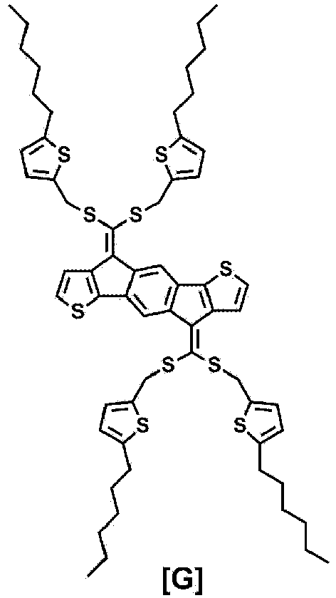
- An organic solar cell was manufactured in the same manner as in Experimental Example 2-1, except that the following Compound H was used instead of
Compound 2 in Experimental Example 2-1.
- The photoelectric conversion characteristics of the organic solar cells manufactured in Experimental Examples 2-1 to 2-6 and Comparative Examples 1 to 3 were measured under the condition of 100 mW/cm2 (AM 1.5), and the results are shown in the following Table 1.
[Table 1] Active layer material Voc (V) Jsc (mA/cm2) FF (%) PCE (%) Experimental Example 2-1 Compound 2/Compound E = 1:20.81 8.28 41.2 2.76 Experimental Example 2-2 Compound 3/Compound E = 1:20.92 13.37 64.4 7.92 Experimental Example 2-3 Compound 4/Compound E = 1:20.84 12.17 53.7 5.48 Experimental Example 2-4 Compound 9/Compound E = 1:20.81 12.92 57.6 6.02 Experimental Example 2-5 Compound 10/Compound E = 1:2 0.81 11.82 61.5 5.88 Experimental Example 2-6 Compound 11/Compound E = 1:20.80 10.57 62.3 5.26 Comparative Example 1 Compound F/Compound E = 1:2 0.075 4.41 25.5 0.084 Comparative Example 2 Compound G/Compound E = 1:2 0.11 3.18 18.2 0.064 Comparative Example 3 Compound H/Compound E = 1:2 0.093 4.32 17.6 0.071 - In Table 1, Voc, Jsc, FF, and PCE mean an open-circuit voltage, a short-circuit current, a fill factor, and energy conversion efficiency, respectively. The open-circuit voltage and the short-circuit current are an X axis intercept and a Y axis intercept, respectively, in the fourth quadrant of the voltage-current density curve, and as the two values are increased, the efficiency of the solar cell is preferably increased. In addition, the fill factor is a value obtained by dividing the area of a rectangle, which may be drawn within the curve, by the product of the short-circuit current and the open-circuit voltage. The energy conversion efficiency may be obtained when these three values are divided by the intensity of the irradiated light, and the higher value is preferred.
- From Table 1, it can be confirmed that the devices (Experimental Examples 2-1 to 2-6), into which the compound to which the groups (Ra and Rb of Formula 1) that serve as an electron acceptor are applied are introduced, have excellent performance, as compared to the devices (Comparative Examples 1 to 3) to which the compounds (Compounds F, H, and G), which have no group that serves as an electron acceptor, are applied.
Claims (11)
- A compound represented by one of the following Formulae 1, A and B:


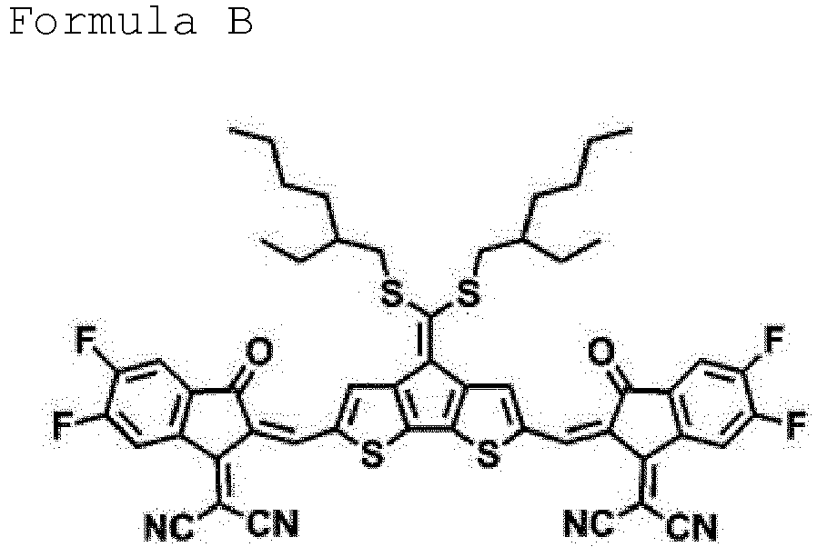 Y1 to Y6 are S;n and m are each an integer from 0 to 5;when n and m are each 2 or more, the structures in the parenthesis are the same as or different from each other;R1 to R6 are the same as or different from each other, and are each independently hydrogen, deuterium, a halogen group, a nitrile group, a nitro group, an imide group, an amide group, a hydroxyl group, a substituted or unsubstituted alkyl group, a substituted or unsubstituted cycloalkyl group, a substituted or unsubstituted alkoxy group, a substituted or unsubstituted aryloxy group, a substituted or unsubstituted alkylthioxy group, a substituted or unsubstituted arylthioxy group, a substituted or unsubstituted alkylsulfoxy group, a substituted or unsubstituted arylsulfoxy group, a substituted or unsubstituted alkenyl group, a substituted or unsubstituted silyl group, a substituted or unsubstituted boron group, a substituted or unsubstituted alkylamine group, a substituted or unsubstituted aralkylamine group, a substituted or unsubstituted arylamine group, a substituted or unsubstituted heteroarylamine group, a substituted or unsubstituted aryl group, or a substituted or unsubstituted heterocyclic group; andRa and Rb are the same as or different from each other, and are each independently an electron withdrawing group selected from the following:
 c is an integer from 1 to 4;when c is 2 or more, the structures in the parenthesis are the same as or different from each other; andR10 to R13 are the same as or different from each other, and are each independently hydrogen, deuterium, a halogen group, a nitrile group, a nitro group, an imide group, an amide group, a hydroxyl group, a substituted or unsubstituted alkyl group, a substituted or unsubstituted cycloalkyl group, a substituted or unsubstituted alkoxy group, a substituted or unsubstituted aryloxy group, a substituted or unsubstituted alkylthioxy group, a substituted or unsubstituted arylthioxy group, a substituted or unsubstituted alkylsulfoxy group, a substituted or unsubstituted arylsulfoxy group, a substituted or unsubstituted alkenyl group, a substituted or unsubstituted silyl group, a substituted or unsubstituted boron group, a substituted or unsubstituted alkylamine group, a substituted or unsubstituted aralkylamine group, a substituted or unsubstituted arylamine group, a substituted or unsubstituted heteroarylamine group, a substituted or unsubstituted aryl group, or a substituted or unsubstituted heterocyclic group;wherein the term "substituted or unsubstituted" means having no substituent or substituted with one or more substituents selected from deuterium, a halogen group, a nitrile group, a nitro group, an imide group, an amide group; a carbonyl group, an ester group, a hydroxyl group, an alkyl group, a cycloalkyl group, an alkoxy group, an aryloxy group, an alkylthioxy group, an arylthioxy group, an alkylsulfoxy group, an arylsulfoxy group, an alkenyl group, a silyl group, a siloxane group, a boron group, an amine group, an arylphosphine group, a phosphine oxide group, an aryl group, and a heterocyclic group, or being substituted with a substituent in which two or more of the aforementioned substituents are linked.
 - The compound of claim 1, wherein Formula 1 is represented by the following Formula 1-1 or 1-2:


- The compound of claim 1, wherein R1 and R2 are the same as or different from each other, and are each independently hydrogen, a halogen group, a substituted or unsubstituted alkyl group, a substituted or unsubstituted alkoxy group, a substituted or unsubstituted aryl group, or a substituted or unsubstituted heterocyclic group.
- The compound of claim 1, wherein R1 and R2 are hydrogen.
- The compound of claim 1, wherein Formula 1 is represented by any one of the following Formulae 1-12, 1-13, 1-15, 1-16, 1-18, 1-19, 1-21 to 1-22:


- The compound of claim 1, wherein R3 to R6 are the same as or different from each other, and are each independently a substituted or unsubstituted alkyl group, a substituted or unsubstituted aryl group, or a substituted or unsubstituted heterocyclic group.
- The compound of claim 1, which is one of the following compounds:


- An organic solar cell comprising:a first electrode (102);a second electrode (106) provided to face the first electrode; andone or more organic material layers provided between the first electrode and the second electrode and comprising a photoactive layer (104);wherein one or more of the organic material layers comprise the compound of any one of claims 1 to 7.
- The organic solar cell of claim 8, wherein the organic material layers comprise a hole transport layer (105), a hole injection layer or a layer which simultaneously transports and injects holes, and the hole transport layer, the hole injection layer or the layer which simultaneously transports and injects holes comprises the compound.
- The organic solar cell of claim 8, wherein the organic material layers comprise an electron transport layer (103), an electron injection layer or a layer which simultaneously transports and injects electrons, and the electron transport layer, the electron injection layer or the layer which simultaneously transports and injects electrons comprises the compound.
- The organic solar cell of claim 8, wherein the photoactive layer (104) comprises an electron donor material and an electron acceptor material, and the electron acceptor material comprises the compound.
Applications Claiming Priority (3)
| Application Number | Priority Date | Filing Date | Title |
|---|---|---|---|
| KR20170035338 | 2017-03-21 | ||
| KR1020180030148A KR102134507B1 (en) | 2017-03-21 | 2018-03-15 | Compound and organic solar cell comprising the same |
| PCT/KR2018/003091 WO2018174476A1 (en) | 2017-03-21 | 2018-03-16 | Compound and organic solar cell comprising same |
Publications (3)
| Publication Number | Publication Date |
|---|---|
| EP3553063A1 EP3553063A1 (en) | 2019-10-16 |
| EP3553063A4 EP3553063A4 (en) | 2020-03-11 |
| EP3553063B1 true EP3553063B1 (en) | 2022-04-27 |
Family
ID=63584458
Family Applications (1)
| Application Number | Title | Priority Date | Filing Date |
|---|---|---|---|
| EP18770716.1A Active EP3553063B1 (en) | 2017-03-21 | 2018-03-16 | Compound and organic solar cell comprising same |
Country Status (2)
| Country | Link |
|---|---|
| EP (1) | EP3553063B1 (en) |
| WO (1) | WO2018174476A1 (en) |
Families Citing this family (2)
| Publication number | Priority date | Publication date | Assignee | Title |
|---|---|---|---|---|
| WO2019086400A1 (en) * | 2017-11-02 | 2019-05-09 | Merck Patent Gmbh | Organic semiconducting compounds |
| CN110283184A (en) * | 2019-06-10 | 2019-09-27 | 湘潭大学 | IDTV organic micromolecule and the preparation method and application thereof |
Family Cites Families (9)
| Publication number | Priority date | Publication date | Assignee | Title |
|---|---|---|---|---|
| TWI383986B (en) * | 2008-12-29 | 2013-02-01 | Eternal Chemical Co Ltd | Diindenothiophene derivatives and use thereof |
| WO2013000532A1 (en) * | 2011-06-28 | 2013-01-03 | Merck Patent Gmbh | Indaceno derivatives as organic semiconductors |
| US20140252279A1 (en) * | 2011-10-20 | 2014-09-11 | Merck Patent Gmbh | Organic semiconductors |
| US9948135B2 (en) | 2015-09-22 | 2018-04-17 | Energous Corporation | Systems and methods for identifying sensitive objects in a wireless charging transmission field |
| KR101732220B1 (en) * | 2014-03-31 | 2017-05-02 | 주식회사 엘지화학 | Heterocyclic compound and organic solar cell comprising the same |
| JP6610096B2 (en) * | 2014-09-24 | 2019-11-27 | 東レ株式会社 | Conjugated compound, electron-donating organic material using the same, photovoltaic device material and photovoltaic device |
| KR101824767B1 (en) * | 2015-02-10 | 2018-02-01 | 주식회사 엘지화학 | Hetero-cyclic compound, unimolecular, polymer and organic electronic device comprising the same |
| KR20170003234A (en) * | 2015-06-30 | 2017-01-09 | 주식회사 엘지화학 | Fused ring derivative and organic solar cell comprising the same |
| NL2017128A (en) | 2015-07-16 | 2017-01-23 | Asml Netherlands Bv | A lithographic apparatus, a projection system, a last lens element, a liquid control member and a device manufacturing method |
-
2018
- 2018-03-16 WO PCT/KR2018/003091 patent/WO2018174476A1/en not_active Ceased
- 2018-03-16 EP EP18770716.1A patent/EP3553063B1/en active Active
Also Published As
| Publication number | Publication date |
|---|---|
| EP3553063A4 (en) | 2020-03-11 |
| EP3553063A1 (en) | 2019-10-16 |
| WO2018174476A1 (en) | 2018-09-27 |
Similar Documents
| Publication | Publication Date | Title |
|---|---|---|
| EP3473627B1 (en) | Heterocyclic compound and organic electronic device comprising same | |
| EP3260456B1 (en) | Thiophene derivative and organic solar cell comprising same | |
| EP3009463A1 (en) | Copolymer and organic solar cell comprising same | |
| EP3121211B1 (en) | Polymer and organic solar cell comprising same | |
| EP3135678A1 (en) | Heterocyclic compound and organic solar cell comprising same | |
| EP3287452B1 (en) | Heterocyclic compound and organic solar cell comprising same | |
| KR102106668B1 (en) | Heterocyclic compound and organic electronic device comprising the same | |
| US11158818B2 (en) | Compound and organic solar cell comprising same | |
| EP3018160B1 (en) | Copolymer and organic solar cell comprising same | |
| EP3012279A1 (en) | Copolymer and organic solar cell comprising same | |
| KR20180005920A (en) | Heterocyclic compound and organic solar cell comprising the same | |
| EP3553063B1 (en) | Compound and organic solar cell comprising same | |
| US20200002468A1 (en) | Compound and Organic Solar Cell Comprising Same | |
| EP3557642B1 (en) | Photoactive layer and organic solar cell including same | |
| KR20170126689A (en) | Heterocyclic compound and organic solar cell comprising the same | |
| KR20200027325A (en) | Polymer and organic solar cell comprising the same | |
| KR20190117086A (en) | Compound and organic solar cell comprising the same | |
| KR102235223B1 (en) | Photoactive layer and organic solar cell comprising the same | |
| KR102285560B1 (en) | Compound and organic solar cell comprising the same | |
| EP3549942B1 (en) | Compound and organic solar cell comprising same | |
| US11239437B2 (en) | Photoactive layer and organic solar cell including same |
Legal Events
| Date | Code | Title | Description |
|---|---|---|---|
| STAA | Information on the status of an ep patent application or granted ep patent |
Free format text: STATUS: THE INTERNATIONAL PUBLICATION HAS BEEN MADE |
|
| PUAI | Public reference made under article 153(3) epc to a published international application that has entered the european phase |
Free format text: ORIGINAL CODE: 0009012 |
|
| STAA | Information on the status of an ep patent application or granted ep patent |
Free format text: STATUS: REQUEST FOR EXAMINATION WAS MADE |
|
| 17P | Request for examination filed |
Effective date: 20190710 |
|
| AK | Designated contracting states |
Kind code of ref document: A1 Designated state(s): AL AT BE BG CH CY CZ DE DK EE ES FI FR GB GR HR HU IE IS IT LI LT LU LV MC MK MT NL NO PL PT RO RS SE SI SK SM TR |
|
| AX | Request for extension of the european patent |
Extension state: BA ME |
|
| REG | Reference to a national code |
Ref country code: DE Ref legal event code: R079 Ref document number: 602018034573 Country of ref document: DE Free format text: PREVIOUS MAIN CLASS: C07D0495040000 Ipc: H01L0051460000 |
|
| A4 | Supplementary search report drawn up and despatched |
Effective date: 20200211 |
|
| RIC1 | Information provided on ipc code assigned before grant |
Ipc: H01L 51/42 20060101ALI20200205BHEP Ipc: H01L 51/00 20060101ALI20200205BHEP Ipc: C07D 495/04 20060101ALI20200205BHEP Ipc: H01L 51/46 20060101AFI20200205BHEP Ipc: C07D 417/14 20060101ALI20200205BHEP |
|
| DAV | Request for validation of the european patent (deleted) | ||
| DAX | Request for extension of the european patent (deleted) | ||
| STAA | Information on the status of an ep patent application or granted ep patent |
Free format text: STATUS: EXAMINATION IS IN PROGRESS |
|
| 17Q | First examination report despatched |
Effective date: 20210527 |
|
| GRAP | Despatch of communication of intention to grant a patent |
Free format text: ORIGINAL CODE: EPIDOSNIGR1 |
|
| STAA | Information on the status of an ep patent application or granted ep patent |
Free format text: STATUS: GRANT OF PATENT IS INTENDED |
|
| INTG | Intention to grant announced |
Effective date: 20211213 |
|
| GRAS | Grant fee paid |
Free format text: ORIGINAL CODE: EPIDOSNIGR3 |
|
| GRAA | (expected) grant |
Free format text: ORIGINAL CODE: 0009210 |
|
| STAA | Information on the status of an ep patent application or granted ep patent |
Free format text: STATUS: THE PATENT HAS BEEN GRANTED |
|
| AK | Designated contracting states |
Kind code of ref document: B1 Designated state(s): AL AT BE BG CH CY CZ DE DK EE ES FI FR GB GR HR HU IE IS IT LI LT LU LV MC MK MT NL NO PL PT RO RS SE SI SK SM TR |
|
| REG | Reference to a national code |
Ref country code: GB Ref legal event code: FG4D |
|
| REG | Reference to a national code |
Ref country code: CH Ref legal event code: EP |
|
| REG | Reference to a national code |
Ref country code: AT Ref legal event code: REF Ref document number: 1487650 Country of ref document: AT Kind code of ref document: T Effective date: 20220515 |
|
| REG | Reference to a national code |
Ref country code: DE Ref legal event code: R096 Ref document number: 602018034573 Country of ref document: DE |
|
| REG | Reference to a national code |
Ref country code: IE Ref legal event code: FG4D |
|
| REG | Reference to a national code |
Ref country code: LT Ref legal event code: MG9D |
|
| REG | Reference to a national code |
Ref country code: NL Ref legal event code: MP Effective date: 20220427 |
|
| REG | Reference to a national code |
Ref country code: AT Ref legal event code: MK05 Ref document number: 1487650 Country of ref document: AT Kind code of ref document: T Effective date: 20220427 |
|
| PG25 | Lapsed in a contracting state [announced via postgrant information from national office to epo] |
Ref country code: NL Free format text: LAPSE BECAUSE OF FAILURE TO SUBMIT A TRANSLATION OF THE DESCRIPTION OR TO PAY THE FEE WITHIN THE PRESCRIBED TIME-LIMIT Effective date: 20220427 |
|
| PG25 | Lapsed in a contracting state [announced via postgrant information from national office to epo] |
Ref country code: SE Free format text: LAPSE BECAUSE OF FAILURE TO SUBMIT A TRANSLATION OF THE DESCRIPTION OR TO PAY THE FEE WITHIN THE PRESCRIBED TIME-LIMIT Effective date: 20220427 Ref country code: PT Free format text: LAPSE BECAUSE OF FAILURE TO SUBMIT A TRANSLATION OF THE DESCRIPTION OR TO PAY THE FEE WITHIN THE PRESCRIBED TIME-LIMIT Effective date: 20220829 Ref country code: NO Free format text: LAPSE BECAUSE OF FAILURE TO SUBMIT A TRANSLATION OF THE DESCRIPTION OR TO PAY THE FEE WITHIN THE PRESCRIBED TIME-LIMIT Effective date: 20220727 Ref country code: LT Free format text: LAPSE BECAUSE OF FAILURE TO SUBMIT A TRANSLATION OF THE DESCRIPTION OR TO PAY THE FEE WITHIN THE PRESCRIBED TIME-LIMIT Effective date: 20220427 Ref country code: HR Free format text: LAPSE BECAUSE OF FAILURE TO SUBMIT A TRANSLATION OF THE DESCRIPTION OR TO PAY THE FEE WITHIN THE PRESCRIBED TIME-LIMIT Effective date: 20220427 Ref country code: GR Free format text: LAPSE BECAUSE OF FAILURE TO SUBMIT A TRANSLATION OF THE DESCRIPTION OR TO PAY THE FEE WITHIN THE PRESCRIBED TIME-LIMIT Effective date: 20220728 Ref country code: FI Free format text: LAPSE BECAUSE OF FAILURE TO SUBMIT A TRANSLATION OF THE DESCRIPTION OR TO PAY THE FEE WITHIN THE PRESCRIBED TIME-LIMIT Effective date: 20220427 Ref country code: ES Free format text: LAPSE BECAUSE OF FAILURE TO SUBMIT A TRANSLATION OF THE DESCRIPTION OR TO PAY THE FEE WITHIN THE PRESCRIBED TIME-LIMIT Effective date: 20220427 Ref country code: BG Free format text: LAPSE BECAUSE OF FAILURE TO SUBMIT A TRANSLATION OF THE DESCRIPTION OR TO PAY THE FEE WITHIN THE PRESCRIBED TIME-LIMIT Effective date: 20220727 Ref country code: AT Free format text: LAPSE BECAUSE OF FAILURE TO SUBMIT A TRANSLATION OF THE DESCRIPTION OR TO PAY THE FEE WITHIN THE PRESCRIBED TIME-LIMIT Effective date: 20220427 |
|
| REG | Reference to a national code |
Ref country code: DE Ref legal event code: R079 Ref document number: 602018034573 Country of ref document: DE Free format text: PREVIOUS MAIN CLASS: H01L0051460000 Ipc: H10K0085000000 |
|
| PG25 | Lapsed in a contracting state [announced via postgrant information from national office to epo] |
Ref country code: RS Free format text: LAPSE BECAUSE OF FAILURE TO SUBMIT A TRANSLATION OF THE DESCRIPTION OR TO PAY THE FEE WITHIN THE PRESCRIBED TIME-LIMIT Effective date: 20220427 Ref country code: PL Free format text: LAPSE BECAUSE OF FAILURE TO SUBMIT A TRANSLATION OF THE DESCRIPTION OR TO PAY THE FEE WITHIN THE PRESCRIBED TIME-LIMIT Effective date: 20220427 Ref country code: LV Free format text: LAPSE BECAUSE OF FAILURE TO SUBMIT A TRANSLATION OF THE DESCRIPTION OR TO PAY THE FEE WITHIN THE PRESCRIBED TIME-LIMIT Effective date: 20220427 Ref country code: IS Free format text: LAPSE BECAUSE OF FAILURE TO SUBMIT A TRANSLATION OF THE DESCRIPTION OR TO PAY THE FEE WITHIN THE PRESCRIBED TIME-LIMIT Effective date: 20220827 |
|
| REG | Reference to a national code |
Ref country code: DE Ref legal event code: R097 Ref document number: 602018034573 Country of ref document: DE |
|
| PG25 | Lapsed in a contracting state [announced via postgrant information from national office to epo] |
Ref country code: SM Free format text: LAPSE BECAUSE OF FAILURE TO SUBMIT A TRANSLATION OF THE DESCRIPTION OR TO PAY THE FEE WITHIN THE PRESCRIBED TIME-LIMIT Effective date: 20220427 Ref country code: SK Free format text: LAPSE BECAUSE OF FAILURE TO SUBMIT A TRANSLATION OF THE DESCRIPTION OR TO PAY THE FEE WITHIN THE PRESCRIBED TIME-LIMIT Effective date: 20220427 Ref country code: RO Free format text: LAPSE BECAUSE OF FAILURE TO SUBMIT A TRANSLATION OF THE DESCRIPTION OR TO PAY THE FEE WITHIN THE PRESCRIBED TIME-LIMIT Effective date: 20220427 Ref country code: EE Free format text: LAPSE BECAUSE OF FAILURE TO SUBMIT A TRANSLATION OF THE DESCRIPTION OR TO PAY THE FEE WITHIN THE PRESCRIBED TIME-LIMIT Effective date: 20220427 Ref country code: DK Free format text: LAPSE BECAUSE OF FAILURE TO SUBMIT A TRANSLATION OF THE DESCRIPTION OR TO PAY THE FEE WITHIN THE PRESCRIBED TIME-LIMIT Effective date: 20220427 Ref country code: CZ Free format text: LAPSE BECAUSE OF FAILURE TO SUBMIT A TRANSLATION OF THE DESCRIPTION OR TO PAY THE FEE WITHIN THE PRESCRIBED TIME-LIMIT Effective date: 20220427 |
|
| PLBE | No opposition filed within time limit |
Free format text: ORIGINAL CODE: 0009261 |
|
| STAA | Information on the status of an ep patent application or granted ep patent |
Free format text: STATUS: NO OPPOSITION FILED WITHIN TIME LIMIT |
|
| PG25 | Lapsed in a contracting state [announced via postgrant information from national office to epo] |
Ref country code: AL Free format text: LAPSE BECAUSE OF FAILURE TO SUBMIT A TRANSLATION OF THE DESCRIPTION OR TO PAY THE FEE WITHIN THE PRESCRIBED TIME-LIMIT Effective date: 20220427 |
|
| 26N | No opposition filed |
Effective date: 20230130 |
|
| PG25 | Lapsed in a contracting state [announced via postgrant information from national office to epo] |
Ref country code: SI Free format text: LAPSE BECAUSE OF FAILURE TO SUBMIT A TRANSLATION OF THE DESCRIPTION OR TO PAY THE FEE WITHIN THE PRESCRIBED TIME-LIMIT Effective date: 20220427 |
|
| PG25 | Lapsed in a contracting state [announced via postgrant information from national office to epo] |
Ref country code: MC Free format text: LAPSE BECAUSE OF FAILURE TO SUBMIT A TRANSLATION OF THE DESCRIPTION OR TO PAY THE FEE WITHIN THE PRESCRIBED TIME-LIMIT Effective date: 20220427 |
|
| REG | Reference to a national code |
Ref country code: CH Ref legal event code: PL |
|
| REG | Reference to a national code |
Ref country code: BE Ref legal event code: MM Effective date: 20230331 |
|
| PG25 | Lapsed in a contracting state [announced via postgrant information from national office to epo] |
Ref country code: LU Free format text: LAPSE BECAUSE OF NON-PAYMENT OF DUE FEES Effective date: 20230316 |
|
| REG | Reference to a national code |
Ref country code: IE Ref legal event code: MM4A |
|
| PG25 | Lapsed in a contracting state [announced via postgrant information from national office to epo] |
Ref country code: LI Free format text: LAPSE BECAUSE OF NON-PAYMENT OF DUE FEES Effective date: 20230331 Ref country code: IT Free format text: LAPSE BECAUSE OF FAILURE TO SUBMIT A TRANSLATION OF THE DESCRIPTION OR TO PAY THE FEE WITHIN THE PRESCRIBED TIME-LIMIT Effective date: 20220427 Ref country code: IE Free format text: LAPSE BECAUSE OF NON-PAYMENT OF DUE FEES Effective date: 20230316 Ref country code: CH Free format text: LAPSE BECAUSE OF NON-PAYMENT OF DUE FEES Effective date: 20230331 |
|
| PG25 | Lapsed in a contracting state [announced via postgrant information from national office to epo] |
Ref country code: BE Free format text: LAPSE BECAUSE OF NON-PAYMENT OF DUE FEES Effective date: 20230331 |
|
| PG25 | Lapsed in a contracting state [announced via postgrant information from national office to epo] |
Ref country code: BG Free format text: LAPSE BECAUSE OF FAILURE TO SUBMIT A TRANSLATION OF THE DESCRIPTION OR TO PAY THE FEE WITHIN THE PRESCRIBED TIME-LIMIT Effective date: 20220427 |
|
| PG25 | Lapsed in a contracting state [announced via postgrant information from national office to epo] |
Ref country code: BG Free format text: LAPSE BECAUSE OF FAILURE TO SUBMIT A TRANSLATION OF THE DESCRIPTION OR TO PAY THE FEE WITHIN THE PRESCRIBED TIME-LIMIT Effective date: 20220427 |
|
| PGFP | Annual fee paid to national office [announced via postgrant information from national office to epo] |
Ref country code: DE Payment date: 20250220 Year of fee payment: 8 |
|
| PGFP | Annual fee paid to national office [announced via postgrant information from national office to epo] |
Ref country code: FR Payment date: 20250221 Year of fee payment: 8 |
|
| PGFP | Annual fee paid to national office [announced via postgrant information from national office to epo] |
Ref country code: GB Payment date: 20250224 Year of fee payment: 8 |
|
| PG25 | Lapsed in a contracting state [announced via postgrant information from national office to epo] |
Ref country code: CY Free format text: LAPSE BECAUSE OF FAILURE TO SUBMIT A TRANSLATION OF THE DESCRIPTION OR TO PAY THE FEE WITHIN THE PRESCRIBED TIME-LIMIT; INVALID AB INITIO Effective date: 20180316 |
|
| PG25 | Lapsed in a contracting state [announced via postgrant information from national office to epo] |
Ref country code: HU Free format text: LAPSE BECAUSE OF FAILURE TO SUBMIT A TRANSLATION OF THE DESCRIPTION OR TO PAY THE FEE WITHIN THE PRESCRIBED TIME-LIMIT; INVALID AB INITIO Effective date: 20180316 |
|
| PG25 | Lapsed in a contracting state [announced via postgrant information from national office to epo] |
Ref country code: TR Free format text: LAPSE BECAUSE OF FAILURE TO SUBMIT A TRANSLATION OF THE DESCRIPTION OR TO PAY THE FEE WITHIN THE PRESCRIBED TIME-LIMIT Effective date: 20220427 |