EP3552955B1 - Methods for launching and landing an unmanned aerial vehicle - Google Patents
Methods for launching and landing an unmanned aerial vehicle Download PDFInfo
- Publication number
- EP3552955B1 EP3552955B1 EP19176060.2A EP19176060A EP3552955B1 EP 3552955 B1 EP3552955 B1 EP 3552955B1 EP 19176060 A EP19176060 A EP 19176060A EP 3552955 B1 EP3552955 B1 EP 3552955B1
- Authority
- EP
- European Patent Office
- Prior art keywords
- uav
- sensor
- signal
- visual
- detected
- Prior art date
- Legal status (The legal status is an assumption and is not a legal conclusion. Google has not performed a legal analysis and makes no representation as to the accuracy of the status listed.)
- Active
Links
Images


Classifications
-
- G—PHYSICS
- G05—CONTROLLING; REGULATING
- G05D—SYSTEMS FOR CONTROLLING OR REGULATING NON-ELECTRIC VARIABLES
- G05D1/00—Control of position, course, altitude or attitude of land, water, air or space vehicles, e.g. using automatic pilots
- G05D1/04—Control of altitude or depth
- G05D1/06—Rate of change of altitude or depth
- G05D1/0607—Rate of change of altitude or depth specially adapted for aircraft
- G05D1/0653—Rate of change of altitude or depth specially adapted for aircraft during a phase of take-off or landing
- G05D1/0661—Rate of change of altitude or depth specially adapted for aircraft during a phase of take-off or landing specially adapted for take-off
- G05D1/0669—Rate of change of altitude or depth specially adapted for aircraft during a phase of take-off or landing specially adapted for take-off specially adapted for vertical take-off
-
- A—HUMAN NECESSITIES
- A63—SPORTS; GAMES; AMUSEMENTS
- A63H—TOYS, e.g. TOPS, DOLLS, HOOPS OR BUILDING BLOCKS
- A63H27/00—Toy aircraft; Other flying toys
- A63H27/12—Helicopters ; Flying tops
-
- B—PERFORMING OPERATIONS; TRANSPORTING
- B64—AIRCRAFT; AVIATION; COSMONAUTICS
- B64U—UNMANNED AERIAL VEHICLES [UAV]; EQUIPMENT THEREFOR
- B64U10/00—Type of UAV
- B64U10/10—Rotorcrafts
-
- B—PERFORMING OPERATIONS; TRANSPORTING
- B64—AIRCRAFT; AVIATION; COSMONAUTICS
- B64U—UNMANNED AERIAL VEHICLES [UAV]; EQUIPMENT THEREFOR
- B64U10/00—Type of UAV
- B64U10/10—Rotorcrafts
- B64U10/13—Flying platforms
- B64U10/14—Flying platforms with four distinct rotor axes, e.g. quadcopters
-
- B—PERFORMING OPERATIONS; TRANSPORTING
- B64—AIRCRAFT; AVIATION; COSMONAUTICS
- B64U—UNMANNED AERIAL VEHICLES [UAV]; EQUIPMENT THEREFOR
- B64U20/00—Constructional aspects of UAVs
- B64U20/80—Arrangement of on-board electronics, e.g. avionics systems or wiring
-
- B—PERFORMING OPERATIONS; TRANSPORTING
- B64—AIRCRAFT; AVIATION; COSMONAUTICS
- B64U—UNMANNED AERIAL VEHICLES [UAV]; EQUIPMENT THEREFOR
- B64U50/00—Propulsion; Power supply
-
- B—PERFORMING OPERATIONS; TRANSPORTING
- B64—AIRCRAFT; AVIATION; COSMONAUTICS
- B64U—UNMANNED AERIAL VEHICLES [UAV]; EQUIPMENT THEREFOR
- B64U60/00—Undercarriages
- B64U60/20—Undercarriages specially adapted for uneven terrain
-
- B—PERFORMING OPERATIONS; TRANSPORTING
- B64—AIRCRAFT; AVIATION; COSMONAUTICS
- B64U—UNMANNED AERIAL VEHICLES [UAV]; EQUIPMENT THEREFOR
- B64U70/00—Launching, take-off or landing arrangements
- B64U70/10—Launching, take-off or landing arrangements for releasing or capturing UAVs by hand
-
- B—PERFORMING OPERATIONS; TRANSPORTING
- B64—AIRCRAFT; AVIATION; COSMONAUTICS
- B64U—UNMANNED AERIAL VEHICLES [UAV]; EQUIPMENT THEREFOR
- B64U70/00—Launching, take-off or landing arrangements
- B64U70/90—Launching from or landing on platforms
- B64U70/95—Means for guiding the landing UAV towards the platform, e.g. lighting means
-
- B—PERFORMING OPERATIONS; TRANSPORTING
- B64—AIRCRAFT; AVIATION; COSMONAUTICS
- B64U—UNMANNED AERIAL VEHICLES [UAV]; EQUIPMENT THEREFOR
- B64U80/00—Transport or storage specially adapted for UAVs
- B64U80/30—Transport or storage specially adapted for UAVs with arrangements for data transmission
-
- G—PHYSICS
- G05—CONTROLLING; REGULATING
- G05D—SYSTEMS FOR CONTROLLING OR REGULATING NON-ELECTRIC VARIABLES
- G05D1/00—Control of position, course, altitude or attitude of land, water, air or space vehicles, e.g. using automatic pilots
- G05D1/0011—Control of position, course, altitude or attitude of land, water, air or space vehicles, e.g. using automatic pilots associated with a remote control arrangement
-
- G—PHYSICS
- G05—CONTROLLING; REGULATING
- G05D—SYSTEMS FOR CONTROLLING OR REGULATING NON-ELECTRIC VARIABLES
- G05D1/00—Control of position, course, altitude or attitude of land, water, air or space vehicles, e.g. using automatic pilots
- G05D1/04—Control of altitude or depth
- G05D1/06—Rate of change of altitude or depth
- G05D1/0607—Rate of change of altitude or depth specially adapted for aircraft
- G05D1/0653—Rate of change of altitude or depth specially adapted for aircraft during a phase of take-off or landing
- G05D1/0676—Rate of change of altitude or depth specially adapted for aircraft during a phase of take-off or landing specially adapted for landing
-
- G—PHYSICS
- G05—CONTROLLING; REGULATING
- G05D—SYSTEMS FOR CONTROLLING OR REGULATING NON-ELECTRIC VARIABLES
- G05D1/00—Control of position, course, altitude or attitude of land, water, air or space vehicles, e.g. using automatic pilots
- G05D1/20—Control system inputs
- G05D1/22—Command input arrangements
- G05D1/221—Remote-control arrangements
- G05D1/222—Remote-control arrangements operated by humans
- G05D1/223—Command input arrangements on the remote controller, e.g. joysticks or touch screens
-
- G—PHYSICS
- G05—CONTROLLING; REGULATING
- G05D—SYSTEMS FOR CONTROLLING OR REGULATING NON-ELECTRIC VARIABLES
- G05D1/00—Control of position, course, altitude or attitude of land, water, air or space vehicles, e.g. using automatic pilots
- G05D1/60—Intended control result
- G05D1/652—Take-off
-
- G—PHYSICS
- G05—CONTROLLING; REGULATING
- G05D—SYSTEMS FOR CONTROLLING OR REGULATING NON-ELECTRIC VARIABLES
- G05D1/00—Control of position, course, altitude or attitude of land, water, air or space vehicles, e.g. using automatic pilots
- G05D1/60—Intended control result
- G05D1/654—Landing
-
- B—PERFORMING OPERATIONS; TRANSPORTING
- B64—AIRCRAFT; AVIATION; COSMONAUTICS
- B64U—UNMANNED AERIAL VEHICLES [UAV]; EQUIPMENT THEREFOR
- B64U2101/00—UAVs specially adapted for particular uses or applications
- B64U2101/30—UAVs specially adapted for particular uses or applications for imaging, photography or videography
-
- B—PERFORMING OPERATIONS; TRANSPORTING
- B64—AIRCRAFT; AVIATION; COSMONAUTICS
- B64U—UNMANNED AERIAL VEHICLES [UAV]; EQUIPMENT THEREFOR
- B64U2101/00—UAVs specially adapted for particular uses or applications
- B64U2101/60—UAVs specially adapted for particular uses or applications for transporting passengers; for transporting goods other than weapons
-
- B—PERFORMING OPERATIONS; TRANSPORTING
- B64—AIRCRAFT; AVIATION; COSMONAUTICS
- B64U—UNMANNED AERIAL VEHICLES [UAV]; EQUIPMENT THEREFOR
- B64U2201/00—UAVs characterised by their flight controls
- B64U2201/10—UAVs characterised by their flight controls autonomous, i.e. by navigating independently from ground or air stations, e.g. by using inertial navigation systems [INS]
-
- B—PERFORMING OPERATIONS; TRANSPORTING
- B64—AIRCRAFT; AVIATION; COSMONAUTICS
- B64U—UNMANNED AERIAL VEHICLES [UAV]; EQUIPMENT THEREFOR
- B64U2201/00—UAVs characterised by their flight controls
- B64U2201/20—Remote controls
Definitions
- UAVs unmanned aerial vehicles
- multi-rotor aircraft For many years, both amateur and professional operators need to spend many hours of practice and training to master the control of unmanned aerial vehicles (UAVs) including multi-rotor aircraft.
- landing and takeoff remain the two most challenging aspects of operating a UAV.
- Such challenge is exacerbated when encountering uneven surfaces, strong wind, and other environmental factors affecting the operation of the UAV. Therefore, there exists a need for simplified or improved methods, as well as new designs of UAV that would render landing and takeoff easier even for amateur UAV users with little training or practice.
- US 2013/0253733 A1 discloses one or more rotor blades; a sensor configured to detect a visual signal generated by an operator of said; a controller configured to provide an actuating signal for activating the in response to the detected visual signal; and an actuator configured to cause the one or more rotor blades to move and generate a lift and/or thrust in response to the actuating signal or the visual signal. It further discloses a method for controlling an unmanned aerial vehicle, UAV, in a flight space using a computing device, a 3D sample database is created and store in a storage device of the computing device.
- the computing device includes a depth-sensing camera that captures a 3D scene image of a scene in front of a user, and senses a depth distance between the user and the depth sensing camera.
- a 3D person image of the user is detected from the 3D scene image, and gesture information of the user is obtained by comparing the 3D person image with human gesture data stored in the 3D sample database.
- the method converts the gesture information of the user into one or more flight control commands, and drives a driver of the UAV to control the UAV to fly in a flight space according to the flight control commands.
- US 2009/0222149 A1 discloses a method for controlling at least one remotely operated unmanned object.
- the method may involve defining a plurality of body movements of an operator that correspond to a plurality of operating commands for the unmanned object. Body movements of the operator may be sensed to generate the operating commands. Wireless signals may be transmitted to the unmanned object that correspond to the operating commands that control operation of the unmanned object.
- the present invention addresses this need and provides related advantages as well.
- the present invention is defined by independent claim 1 defining a method for launching an unmanned rotorcraft, independent claim 4 defining an unmanned aerial vehicle, independent claim7 defining a method for landing an unmanned aerial vehicle and independent claim 11 defining an unmanned aerial vehicle.
- independent claim 1 defining a method for launching an unmanned rotorcraft
- independent claim 4 defining an unmanned aerial vehicle
- independent claim7 defining a method for landing an unmanned aerial vehicle
- independent claim 11 defining an unmanned aerial vehicle.
- the detection of a visual signal can involve detecting a gesture or movement of a human body.
- detecting the release of the grip of the UAV by a hand results in one or more of: setting in motion in an arched trajectory, tossing into the air, catapulting into the air, and retracting or allowing said rotorcraft to fall towards the earth.
- the release can be effected by releasing any part of the UAV.
- the release can involve the release of a hook, a rod, a rope, a bump, a hole, a landing leg, a structural extension, or a loop on the UAV.
- the detection of the release can be performed by one or more of the following sensors including without limitation, a touch sensor, a pressure sensor, a temperature sensor, a photosensor, and a magnet.
- the detected positional change, visual signal, and/or release of the grip to the UAV may trigger the activating the UAV resulting in a lift and/or thrust.
- the lift and/or thrust is generated in less than about 60 seconds, 30 seconds, 10 seconds, 8 seconds, 6 seconds, 5 seconds, 4 seconds, 3 seconds, 2 seconds, 1 second, 0.5 second, 0.1 second, or even 0.01 second upon detecting the said detecting the positional change, visual signal, and/or release of the grip to the UAV.
- the activation of the UAV may involve activating one or more rotor blades of a UAV.
- the activation of the UAV is performed when the UAV reaches a vertical velocity of zero.
- the UAV of any of the foregoing embodiments can be a rotorcraft including but not limited to the type with multiple rotor blades (multi-rotor aircraft).
- the sensor for detecting the release of the grip of the UAV by a hand is a touch sensor, a pressure sensor, a temperature sensor, or any combination thereof.
- the actuator includes without limitation a DC brushless motor, DC brush motor, and switched reluctance motor.
- the actuator is configured to cause the one or more rotor blades to move and generate a lift and/or thrust in less than about 60 seconds, 30 seconds, 10 seconds, 8 seconds, 6 seconds, 5 seconds, 4 seconds, 3 seconds, 2 seconds, 1 second, 0.5 second, 0.1 second, or even 0.01 second, in response to the actuating signal, which is in turn generated when the positional change, visual signal, and/or release of the grip to the UAV is detected.
- the UAV comprises a holding member attached thereto.
- Such holding member can be a handle, rod, rope, a landing leg, a structural extension, a hook, a loop, or any structural component amendable to be held by a mechanical or human hand.
- the external contact can be detected by a sensor selected from the group consisting of a touch sensor, pressure sensor, temperature sensor, photosensor, a magnet, or a combination thereof.
- the sensor can be configured to detect the external contact exerted by way of capturing said holding member by a hand.
- the method may further comprise determining that the UAV has been captured by a human hand for period of time that exceeds a predetermined threshold value and causing the UAV to come to a stop based on said determination.
- practicing this method utilizes a UAV that is a rotorcraft including one or more rotor blades, and said decelerating causes the one or more rotor blades to slow down, stall, or come to a complete stop.
- the decelerating signal effects landing of said UAV at a designated location.
- the decelerating can include without limitation one or more of the following: causing a decrease in altitude of the UAV, causing a change in attitude of the UAV, causing a reduction in velocity of the UAV, and causing a negative change in acceleration of the UAV.
- the decelerating signal is generated by a controller located in said UAV.
- the decelerating signal is generated in less than about 60 seconds, 30 seconds, 10 seconds, 8 seconds, 6 seconds, 5 seconds, 4 seconds, 3 seconds, 2 seconds, 1 second, 0.5 second, 0.1 second, or even 0.01 second,1 second from detecting said external contact.
- the visual signal being detected includes but is not limited to a gesture or movement of a human body.
- the visual signal can detected by a visual sensor (including but not limited to a camera) located on- or off- board the UAV.
- the visual sensor is configured to be in communication with a controller of said UAV, said controller generating the deceleration signal to bring said UAV to a stop.
- the UAV is brought to a stop in less than about 60 seconds, 30 seconds, 10 seconds, 8 seconds, 6 seconds, 5 seconds, 4 seconds, 3 seconds, 2 seconds, 1 second, 0.5 second, 0.1 second, or even 0.01 second, from detecting said positional change or said visual signal.
- the UAV is a rotorcraft including one or more rotor blades, and wherein said decelerating signal causes the one or more rotor blades to slow down, stall, or come to a complete stop.
- the present invention provides methods and apparatus for launching and landing unmanned aerial vehicle (UAV). According to an aspect of the present invention, simplified methods of launching the UAVs are provided.
- the subject methods are generally user friendly, designed for automatic launch by even armatures with little training on UAV operation, and thus improving user experience and accessibility.
- the subject methods can permit taking off and/or landing on uneven surface or rough terrain, thus also accommodating a wide range of environmental conditions conventionally unsuited for UAV operation.
- a method for launching an unmanned aerial vehicle comprises the step of (a) detecting a positional change of the UAV; and (b) in response to the detected positional change, activating the UAV to generate a lift and/or thrust.
- a positional change may include translational changes (e.g., in altitude, latitude and/or longitude) or rotational changes.
- a positional change may also include changes in the velocity, acceleration, and/or orientation of the UAV.
- a positional change may further include a change in location of the UAV with respect to a frame of reference or a reference object.
- the positional change or positional state may be detected by onboard and/or off-board sensors such as discussed herein.
- the positional change may be detected by an inertial sensor, GPS receiver, compass, magnetometer, altimeter, proximity sensor (e.g., infrared sensor, LIDAR sensor), visual or image sensor (such as a camera or video camera), photo sensor, motion detector, and the like.
- an onboard inertial sensor including one or more gyroscopes and/or accelerometers
- the inertial sensor may be used to detect that the acceleration of the UAV is close to the gravity of the earth indicating that the UAV is experiencing the freefall motion.
- the inertial sensor and/or visual sensor may be used to determine that the vertical velocity of the UAV is close to zero, indicating for example that the UAV is near the vertically highest point of the a parabola-like trajectory.
- an onboard GPS receiver and/or visual sensor may be used to detect a change in the location of the UAV.
- detecting the positional change or positional state may include analyzing sensor data obtained from the sensors. Such analysis may be performed by a controller of the UAV, a computer or processor at a remote device or station. In some cases, obtained sensor data may be compared against a threshold and/or predetermined value. In such cases the UAV may utilize a variety of different sensors with built-in threshold limits.
- the threshold values may include absolute or relative values, depending on the specific positional change to be determined.
- the threshold value may include the absolute or relative velocity, acceleration, orientation, location coordinates (e.g., altitude, latitude, and/or longitude), and the like.
- a detected linear acceleration may be compared with the absolute value of g (gravity).
- the detected velocity may be compared with the absolute value of zero to determine if the velocity has reached zero, close to zero or has become negative (such as when the UAV has reached or passed the apex of a launching trajectory).
- the obtained sensor data may be compared with previously obtained sensor data. For example, frames of image data obtained from visual sensors may be compared and analyzed to determine changes in velocity and/or location of the UAV since last time the sensor data is obtained and/or the currently velocity and/or location of the UAV.
- an acceleration or activation signal may be generated, for example, by the onboard controller or a remote computer, to actuate one or more rotors of the UAV, thereby causing one or more rotor blades to rotate and generate a suitable lift for the UAV.
- the generated lift may be sufficient to allow the UAV to maintain an airborne state.
- the generated lift allows the UAV to hover over a designated location.
- the generated lift allows the UAV to gain elevation.
- the generated lift may also allow the UAV to change its lateral position and/or orientation.
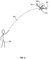
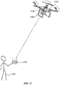
- FIG. 8 illustrates a method for launching a UAV, in accordance with an embodiment of the present invention.
- a person 801 throws or tosses a UAV 802 with non-rotating rotor blades into the air in an arc-like trajectory 803.
- the vertical velocity of the UAV becomes zero or close to zero.
- Such zero or near-zero vertical velocity can be detected by an onboard or off-board sensor.
- the zero or near-zero vertical velocity may be detected by an inertial sensor and/or visual sensor of the UAV 802.
- the sensor may provide the detected data to an onboard controller of the UAV or a remote controller, for example, via a wired or wireless link.
- the controller may determine, in response to the detected positional change or state, the suitable actuation signals to provide to one or more rotors of the UAV.
- the actuation signals may be generated by an onboard controller, a remote device or a combination thereof.
- the actuation signals may cause actuation of the one or more rotors, thereby causing rotation of respective rotor blades 801 to generate the desired lift 807 sufficient to cause the UAV to become autonomously airborne. For example, UAV may hover over the peak of the trajectory.
- the release of the UAV by a human hand may be detected.
- the present disclosure provides a method for launching an unmanned rotorcraft having (1) one or more rotor blades and (2) at least one sensor being configured to detect release of a grip of said rotorcraft by a hand.
- the method typically involves the steps of (a) detecting by a sensor on a UAV, the release of the grip by said hand; and (b) in response to the detected release of the grip, generating an activating signal to actuate the one or more rotor blades of the UAV to generate a lift and/or thrust.
- a UAV may be released by the person 801 of Figure 8 via one or more holding members 810 such as discussed herein.
- the holding members may be provided with one or more sensors such as touch sensor, pressure sensor, temperature sensor and the like to detect the contact or the lack thereof with the holding members.
- the release of the UAV from a mechanical or human hand may be detected by such sensors and in response to the detected release.
- an onboard or remote controller of the UAV then generate the actuation signals that cause the activation of the UAV as described herein.
- the actuation signals may be generated within less than about 1 second from the detecting step. In other embodiments, activating signal is generated within a range from as little as about 0.8 seconds, 0.5 seconds, 0.3 seconds, 0.1 seconds, 0.05 seconds, to about .001 second or less from the detecting step. In some instances, activating the one or more rotor blades to generate a lift and/or thrust is performed within less than about 1 second from the detecting step. In other embodiments, activating signal is generated within a range from as little as about 0.8 seconds, 0.5 seconds, 0.3 seconds, 0.1 seconds, 0.05 seconds, to about .001 second or less from the detecting step.
- FIG. 9A illustrates an example mechanical device for launching an UAV, in accordance with an embodiment of the present invention.
- the mechanical device includes a mechanical arm 900 that comprises a mechanical hand 906 at one end and an actuator 911 at the other end.
- the mechanical hand 906 may be configured to hold and/or release a UAV 902.
- the actuator 911 may include a mechanical motor, electrical motor, spring assembly or any other suitable actuator.
- the actuator 911 may be controlled locally or remotely by a controller or computer.
- the actuator 911 may cause the mechanical arm and/or hand to launch the UAV 902 into the air in a similar fashion as the launch by the human hand as discussed above in connection with FIG.
- the UAV may autonomously start or activate the rotors and rotor blades in response to detected positional change of the UAV and/or detected release of the UAV from the mechanical hand 906, similar to that discussed in connection with FIG. 8 .
- an onboard controller of the UAV may cause one or more rotors to activate the corresponding rotor blades 901, thereby generating the desired lift and/or thrust 907 that causes the UAV to become autonomously airborne.
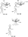
- FIG. 10A illustrates another method for launching a UAV 1002, in accordance with an embodiment of the present invention.
- an UAV 1002 is initially held by a hand 1003 of a human 1001.
- the UAV may be supported by a human body or a human hand.
- the UAV may be supported by one or more support members such landing stands or legs.
- the UAV may be placed directly on the human body or hand without any support members.
- the UAV may be held by the hand via one or more holding members 1005 such as discussed herein.
- the UAV may be supported by any other object such as a removable hard surface.
- the rotors of the UAV are not actuated and the rotor blades are not moving.
- the person may withdraw the support of the hand from the UAV or simply drop the UAV from an elevation position.
- the hand may be withdrawn from underneath the UAV.
- the holding members may be released, thus releasing the UAV.
- acceleration of the UAV typically changes from zero or close to zero to around g (gravity of earth), thus experiencing freefall.
- Such a change of acceleration may be detected by the UAV, for example, by an inertial sensor.
- the UAV may also detect the release of the UAV, for example, by a contact sensor (e.g., touch sensor, pressure sensor, or temperature sensor).
- a contact sensor e.g., touch sensor, pressure sensor, or temperature sensor.
- the UAV may spontaneously and autonomously actuate the rotors (and corresponding rotor blades) to generate the desired lift and/or thrust 1035.
- the desired lift and/or thrust 1035 may cause the UAV to hover over or gain elevation relative to the location where the UAV was originally held in FIG. 10A .
- the post-release altitude of the UAV may be less than the original altitude. Regardless of the post-release position of the UAV, the UAV becomes airborne in an autonomous fashion (i.e., without external support).
- visual sensors may be used to detect external signals for launching the UAV.
- the method may involve an audio sensor configured to detect a sound signal which can be a command for launching the UAV.
- a wide variety of visual sensors are useful for detecting the external signals for launching the UAV.
- any visual sensor capable of detecting optical wavelengths within the visible spectrum of a naked eye, infra-red, or ultraviolet wavelength ranges, whether being polarized, high intensity light and/or other types of light wavelengths, are suited for practicing the subject methods.
- the sensor can be a camera or video camera, placed on-board or off-board of the UAV.
- some of the onboard sensors may transmit sensor data to an onboard controller, which in turn provides the sensor data to the remote controller.
- some of the onboard sensors may transmit the sensor data directly to the remote control device, e.g., as shown 1720 of Figure 17 .
- Various aspects of the sensing and controlling functionalities may be implemented by onboard systems, off-board systems, or a combination thereof.
- the external signal being detected is a visual signal, a voice command, a gesture or movement of an object such as a body part.
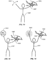
- FIGs. 13-15 illustrate exemplary methods for launching the UAV, in accordance with this embodiment of the present invention.
- a gesture 1310 may be detected by an onboard sensor 1305 and used to trigger the launching of the UAV such as discussed herein.
- the gesture may be made by any body part such as by a hand, arm, head, facial features, eye, and the like.
- the gesture may include the wave of a hand or arm, the turn of the head, the movement of the eye, and the like.
- a recognizable visual sign, symbol or pattern 1410 may be detected by the onboard sensor 1405 and used to trigger the launching of the UAV.
- Such predetermined visual sign, symbol or pattern may be of predetermined color, shape, dimension, size and the like.
- light source 1510 may be detected by an onboard sensor 1505 and used to trigger the launching of the UAV such as discussed herein.
- the light source 1510 may include any light sources so as to provide RGB, UV, NUV, IR, polarized, high intensity light and/or other types of light. The light may be of various wavelengths and modulated in power over time.
- the gesture or movement for launching the UAV may include throwing the UAV into the air, releasing or dropping the UAV from an elevated position, or providing predetermined external signals to the UAV, and the like. Such launching methods may be implemented by a human, mechanical device, or a combination thereof.
- various on-board and/or off-board sensors may be used to detect positional changes of the UAV, or external signals (including but not limited to visual signals), or release of a grip of the UAV. Based on the detected changes or signals, an activating signal may be generated, for example, by the onboard controller or a remote computer, to actuate one or more rotors of the UAV, thereby causing one or more rotor blades to rotate and generate a suitable lift for the UAV.
- the generated lift may be sufficient to allow the UAV to maintain an airborne state. In some embodiments, the generated lift allows the UAV to hover over a designated location. In some other embodiments, the generated lift allows the UAV to gain elevation. In yet some other embodiments, the generated lift may also allow the UAV to change its lateral position and/or orientation.
- the present invention also provides simplified methods of decelerating a UAV, which can be readily adopted by a UAV user with little or no training on UAV operation.
- the deceleration method can effect landing of a UAV at a designated location with little practice by the UAV user.
- the method of landing a UAV involves the steps of (a) detecting by a sensor on the UAV, an external contact exerted upon said UAV while said UAV is airborne; and (b) generating by said UAV a decelerating signal in response to the detected external contact, thereby decelerating said UAV.
- the contact may be exerted while the UAV is airborne.
- the external contact may be detected by one or more onboard and/or off-board sensors such as touch sensor, pressure sensor, temperature sensor, photosensor, magnet, visual sensor, or a combination thereof.
- one or more decelerating or deactivation signals for causing the rotors to slow down or come to be complete stop.
- Such signals may be generated by an onboard controller or a remote device. In some embodiments, such signals may cause the UAV to land at a designated location.
- such external contact may be imposed by a human hand.
- the person may touch, grasp or otherwise hold a portion of the UAV (e.g., a holding member) while the UAV is airborne.
- a portion of the UAV e.g., a holding member
- the person may reach out and get hold of the UAV by hand or by any other suitable device such as a hook, clasp, mechanical arm/hand, or the like.
- the UAV may detect such contact by an onboard sensor such as those described herein and autonomously slows down or stops the rotors (and hence rotor blades) of the UAV causing the UAV to decelerate or come to a stop.
- FIG. 9B illustrates an example mechanical device for landing an UAV, in accordance with an embodiment of the present invention.
- the mechanical device may be similar to that described in connection with FIG. 9A .
- the mechanical device may include a mechanical arm 900, a mechanical hand 906 and an actuator 911.
- the actuator 911 may be configured to control the mechanical arm and/or mechanical hand to capture a UAV 902 that is within a predetermined range.
- the mechanical hand may be controlled grasping or otherwise engaging with one or more holding members 910 of the UAV so as to capture the UAV.
- An onboard sensor 905 may be configured to detect the contact of the mechanical hand and as a result, autonomously slows down or stops the rotation of one or more rotor blades 901.
- the UAV may be configured to detect contact with other external objects such as a landing surface (e.g., ground or table top) and slows down or stops the UAV in response.
- a landing surface e.g., ground or table top
- the UAV may be configured to detect the contact by a human hand.
- an onboard temperature sensor may be configured to detect human body temperature on a holding member as a result of a holding of a human hand, thereby triggering the landing of the UAV.
- other biometric sensors such as fingerprint sensors may be used to detect human contact.
- the decelerating or deactivation signals are generated only after the contact is sustained for a predetermined period of time. This may be useful for preventing the UAV from being shut down due to temporary and unintentional external contact.
- external contact may be used in combination with other sensor input such as positional changes and/or visual signals to determine whether to land the UAV.
- the decelerating signal is generated within less than about 1 second from detecting the external signal. In other embodiments, decelerating signal is generated within a range from as little as about 0.8 seconds, 0.5 seconds, 0.3 seconds, 0.1 seconds, 0.05 seconds, to about .001 second or less from the point when the external signal is detected. In some instances, decelerating the UAV is performed within less than about 1 second from the point when the external signal is detected. In other embodiments, decelerating the UAV is performed within a range from as little as about 0.8 seconds, 0.5 seconds, 0.3 seconds, 0.1 seconds, 0.05 seconds, to about .001 second or less from the detecting step.
- positional changes may be used to trigger automatic landing of the UAV in addition to or instead of external contact with the UAV.
- the present disclosure provides a landing method is provided that involves the step of (a) detecting a positional change of the UAV while said UAV is airborne by the UAV; and (b) in response to the detected positional change and/or the visual signal, generating a deceleration signal to said UAV to bring said UAV to a stop.
- the positional change may include translational changes (e.g., in altitude, latitude and/or longitude) or rotational changes.
- the positional changes may include changes in the velocity, acceleration, and/or orientation of the UAV.
- the positional change may also include a change in location with respect to a frame of reference or a reference object.
- the positional change may be detected by an inertial sensor, GPS receiver, compass, magnetometer, altimeter, infrared sensor, visual or image sensor (such as a camera or video camera), photo sensor, motion detector, and the like.
- the positional change may be caused by a human or a mechanical device.
- FIGs. 11A-B and 12 illustrates exemplary methods for landing an UAV, in accordance with some embodiments.
- an airborne UAV 1102 with rotating rotor blades is caught by a hand of a human 1101 via a holding member 1104 of the UAV.
- the mere act of holding the holding member may cause the UAV to decelerate or stop.
- an additional positional change of the UAV is required besides holding of the UAV.
- Such an additional positional change may include a change in the orientation of the UAV such as by tilting or turning the UAV by a certain angle 1152 along a particular rotational axis.
- Such rotational changes may be detected, for example, by an inertial sensor or a visual sensor 1105 of the UAV.
- the positional change may include a sudden acceleration or deceleration caused by external forces (e.g., human). For example, while holding the UAV, the person may suddenly fling the UAV toward a certain direction causing a sudden acceleration of the UAV.
- Such acceleration or deceleration may be detected by an onboard sensor such an as an inertial sensor and used to trigger the deceleration of the UAV.
- FIG. 12 illustrates another example of positional change of the UAV, in accordance with an example which is not part of the present invention.
- the UAV 1202 is not only held by a human 1201 via a holding member 1204 but also moved in a predetermined pattern 1206 such as in a substantially circular pattern, from side to side, in a figure "8 " pattern, or in any other suitable pattern.
- the movement pattern may be detected by one or more sensors described herein such as inertial sensors, visual sensors, motion sensors and the like.
- the combination of the detected external contact and the detected positional change triggers the slowing down or stopping of the rotor blades of the UAV.
- external signals may be used to trigger the landing of the UAV in addition to or instead of the external contact and/or positional changes.
- Such external signals may include visual signals, audio signals, gesture signals or a combination thereof.
- a subject landing method involves the steps of: (a) detecting a visual signal generated by an operator of said UAV; and (b) in response to the detected positional change and/or the visual signal, generating a deceleration signal to said UAV to bring said UAV to a stop.
- a gesture 1310 may be detected by an onboard sensor 1305 and used to trigger the landing of the UAV such as discussed herein.
- the gesture may be made by any body part such as by a hand, arm, head, facial features, eye, and the like.
- a recognizable visual sign, symbol or pattern 1410 may be detected by the onboard sensor 1405 and used to trigger the landing of the UAV.
- Such predetermined visual sign, symbol or pattern may be of predetermined color, shape, dimension, size and the like.
- light source 1510 may be detected by an onboard sensor 1505 and used to trigger the landing of the UAV such as discussed herein.
- the landing of the UAV may be triggered by the external contact, external signal, any other sensing mechanisms or any combination thereof.
- the external signals are used in conjunction with detected external contact with the UAV (e.g., the holding of the holding member 1304, 1404 or 1504 of FIGs. 13, 14 or 15 , respectively) to cause the landing of the UAV.
- positional changes are used in conjunction with external contact to trigger the landing of the UAV.
- positional changes may be used in combination with external signals to trigger the landing of the UAV.
- external contact, positional changes and external signals may be used together to trigger the landing of the UAV.
- the sensors and the controllers may be located onboard and/or off-board the UAV.
- both the sensors and the controllers are located onboard the UAV.
- both the sensors and the controllers can be located off-board the UAV.
- some sensors are located onboard the UAV while the other sensors are located off-board the UAV.
- some controllers are located onboard the UAV while the other controllers are located off-board the UAV.
- the subject launching and decelerating methods can be implemented by a wide range of UAVs.
- the subject UAVs exhibit one or more unique features as described herein.
- the present invention provides an unmanned aerial vehicle (UAV), comprising: (a) one or more rotor blades; (b) a sensor configured to detect a visual signal generated by an operator of said UAV, and a release of a grip by a hand onto said UAV; (c) a controller configured to provide an actuating signal for activating the UAV in response to the visual signal and the release of grip; and (d) an actuator configured to cause the one or more rotor blades to move and generate a lift and/or thrust in response to the actuating signal or the visual signal.
- UAV unmanned aerial vehicle
- the present invention provides an unmanned aerial vehicle (UAV), comprising: a sensor configured to detect a positional change experienced by the UAV and/or a visual signal generated by an operator of said UAV; a controller configured to provide a deactivating signal for decelerating the UAV in response to the detected positional change and/or the visual signal; and an actuator configured to cause said UAV to decelerate in response to the deactivating signal.
- UAV unmanned aerial vehicle
- FIG. 16 illustrates an exemplary setup.
- a remote control device 1620 operated by an operator 1601, is in wireless communication with both onboard sensors 1605 of the UAV 1602 and an off-board sensing system 1630.
- the off-board sensing system 1630 may include one or more sensors mounted on external structures (fixed or movable) such as a pole, a building, a vehicle, a human or animal, and the like.
- sensor data from the off-board sensing system and/or the onboard sensors may be provided to a remote or off-board controller which may be implemented by the remote control device 1620, remote computer (such as in a base station) or processor, or the like.
- the remote controller may determine whether to trigger automatic launching or landing of the UAV and may provide the corresponding commands or signals to the UAV as a result.
- sensor data from the off-board sensing system and/or the onboard sensors may be provided to an onboard controller instead of or in addition to the remote controller.
- aspects of the controller functionalities discussed herein may be implemented by onboard controllers, off-board controllers or a combination thereof.
- autonomous landing is implemented by off-board controllers whereas autonomous launching is implemented by on-board controllers. In some other embodiments, autonomous launching is implemented by off-board controllers whereas autonomous landing is implemented by on-board controllers. In some other embodiments, both autonomous launching and landing are implemented by the onboard controllers. In some other embodiments, both autonomous launching and landing are implemented by the off-board controllers.
- FIG. 17 illustrates another exemplary setup for implementing the present invention, in accordance with an embodiment.
- remote control device 1720 operated by an operator 1701, is in wireless communication with various onboard sensors 1705 and 1730 of the UAV 1702.
- the sensor 1705 may be a positional sensor such as an inertial sensor, GPS receiver, magnetometer, or the like.
- the sensor 1730 may be a visual sensor such as a camera or video camera.
- some of the onboard sensors may transmit sensor data to an onboard controller, which in turn provides the sensor data to the remote controller.
- some of the onboard sensors may transmit the sensor data directly to the remote control device 1720.
- various aspects of the sensing and controlling functionalities may be implemented by onboard systems, off-board systems, or a combination thereof.
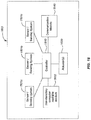
- FIG. 18 illustrates exemplary components of a system 1800 used to implement the present invention, in accordance with an embodiment.
- the system 1800 includes a controller 1810 operatively coupled to one or more sensors or sensing systems 1801a-c via a wired or wireless connection.
- the sensors may be connected to the controller via a controller area network (CAN).
- the controller 1810 can also be operatively coupled to one or more actuators 1820 for controlling the state of the UAV.
- CAN controller area network
- the sensors may include any sensors discussed herein, such as inertial sensor, GPS receiver, compass, magnetometer, altimeter, proximity sensor (e.g., infrared sensor or LIDAR sensor), visual or image sensor (such as a camera or video camera), photo sensor, motion detector, touch sensor, pressure sensor, temperature sensor, photosensor, magnetic sensor, and the like.
- proximity sensor e.g., infrared sensor or LIDAR sensor
- visual or image sensor such as a camera or video camera
- photo sensor motion detector
- touch sensor e.g., touch sensor
- pressure sensor e.g., pressure sensor, temperature sensor, photosensor, magnetic sensor, and the like.
- some sensors may be optionally coupled to a field programmable gate array (FPGA, not shown).
- the FPGA can be operatively coupled to the controller (e.g., via a general purpose memory controller (GPMC) connection).
- some sensors (such as visual sensors) and/or the FPGA can be optionally coupled to a transmission module.
- the transmission module can be used to transmit data captured by the sensors (e.g., image data) to any suitable external device or system, such as a terminal or remote device as described herein.
- the controller can include one or more programmable processors (e.g., a central processing unit (CPU)).
- the controller can be operatively coupled to a non-transitory computer readable medium 1830.
- the non-transitory computer readable medium can include one or more memory units (e.g., removable media or external storage such as an SD card, random access memory (RAM)).
- data from the sensors e.g., camera
- DMA direct memory access
- the memory units of the non-transitory computer readable medium can include code and/or program instructions executable by the controller to perform any suitable embodiment of the methods described herein.
- the controller can be configured to execute instructions causing one or more processors of the controller to analyze data produced by one or more sensors or sensing systems to determine positional and/or motion information of the UAV, the detected external contact information, and/or the detected external signal information, as described herein.
- the controller can be configured to execute instructions causing one or more processors of the controller to determine whether the autonomously launch or land the UAV.
- the memory units of the non-transitory computer readable medium 1830 store sensor data from the one or more sensing systems to be processed by the controller.
- the memory units of the non-transitory computer readable medium can store the positional and/or motion information of the UAV, the detected external contact information, and/or the detected external signal information.
- the memory units of the non-transitory computer readable medium can store predetermined or pre-stored data for controlling the UAV (e.g., predetermined threshold values for sensor data, parameters for controlling the actuators, predetermined flight path, velocity, acceleration or orientation of the UAV).
- the controller 1810 can be used to adjust the state of the UAV via one or more actuators 1820.
- the controller may be used to control the rotors of the UAV (e.g., rotational speed of the rotors) so as to adjust the spatial disposition of the UAV or a component thereof (e.g., a payload, a carrier of the payload) with respect to up to six degrees of freedom (three translational movement (along the X, Y and Z axes) and three rotational movement (along the roll, pitch and yaw axes)).
- the controller can be configured to adjust the velocity or acceleration of the UAV with respect to six degrees of freedom.
- the controller can control the UAV based on predetermined control data or positional, external contact or external signal information for the UAV obtained by processing data from one or more sensing systems, as described herein. For example, the controller may provide acceleration or deceleration signals to the actuators based on the determination of whether launching or landing is required.
- the actuators can include an electric motor, mechanical actuator, hydraulic actuator, pneumatic actuator, and the like.
- Electric motors can include magnetic, electrostatic, or piezoelectric motors.
- the actuator includes a brushed or brushless DC electric motor.
- the controller can be operatively coupled to a communication module 1840 configured to transmit and/or receive data from one or more external devices (e.g., a terminal, display device, or other remote controller).
- a communication module 1840 configured to transmit and/or receive data from one or more external devices (e.g., a terminal, display device, or other remote controller).
- Any suitable means of communication can be used, such as wired communication or wireless communication.
- the communication module can utilize one or more of local area networks (LAN), wide area networks (WAN), infrared, radio, WiFi, peer-to-peer (P2P) networks, telecommunication networks, cloud communication, and the like.
- relay stations such as towers, satellites, or mobile stations, can be used.
- Wireless communications can be proximity dependent or proximity independent. In some embodiments, line-of-sight may or may not be required for communications.
- the communication module can transmit and/or receive one or more of sensor data from the sensing systems, positional and/or motion information, external contact information and/or external signal information determined by processing the sensor data, predetermined control data, user commands from a terminal or remote controller, and the like.
- the components of the system can be arranged in any suitable configuration.
- one or more of the components of the system can be located on the UAV, carrier, payload, terminal, sensing system, or any other remote device or system in communication with one or more of the above.
- FIG. 18 depicts a single controller and a single non-transitory computer readable medium, one of skill in the art would appreciate that this is not intended to be limiting, and that the system can include a plurality of controllers and/or non-transitory computer readable media.
- one or more of the plurality of controllers and/or non-transitory computer readable media can be situated at different locations, such as on the UAV, carrier, payload, terminal, sensing system, or any other remote device or system in communication with one or more of the above, or suitable combinations thereof, such that any suitable aspect of the processing and/or memory functions performed by the system can occur at one or more of the aforementioned locations.
- the subject UAVs alone or for operation in the context of a system as disclosed herein, include without limitation single-rotor aircraft, multi-rotor aircraft, and rotary-wing aircraft.
- Rotary-wing aircraft typically utilizes lift generated by rotor blades, which revolve around a mast or shaft.
- rotorcrafts may include helicopters, cyclocopters, autogyros, gyrodynes, and the like.
- Such rotorcrafts may have more than one rotor fixed about the craft in more than one location.
- the subject UAVs may include quadcopters, hexacopters, octocopters, and the like.
- the UAVs may move freely with respect to up to six degrees of freedom (e.g., three degrees of freedom in translation and three degrees of freedom in rotation).
- the movement of the UAV may be constrained with respect to one or more degrees of freedom, such as by a predetermined path or track.
- the movement can be actuated by any suitable actuation mechanism, such as an engine or a motor.
- the UAV may be driven by a propulsion system. Examples of propulsion systems may include engines, motors, wheels, axles, magnets, rotors, propellers, blades, nozzles, or any suitable combination thereof.
- the movement of the UAV may be powered by any suitable energy source, such as electrical energy, magnetic energy, solar energy, wind energy, gravitational energy, chemical energy, nuclear energy, or any suitable combination thereof.
- the subject UAVs may adopt different sizes, dimensions and/or configurations.
- the subject UAVs may be multi-rotor UAVs where the distance between the shafts of opposing rotors does not exceed a certain threshold value.
- a certain threshold value may be around 5 meters, 4 meters, 3, meters, 2 meters, 1 meter, or the like.
- the values of the distance between shafts of opposing rotors may be 350 millimeters, 450 millimeters, 800 millimeters, 900 millimeters and the like.
- the UAV may be of a size and/or dimensions sufficient to accommodate a human occupant within or on the UAV.
- the UAV may be of size and/or dimensions smaller than that capable of having a human occupant within or on the UAV.
- the UAV may have a maximum dimension (e.g., length, width, height, diameter, diagonal) of no more than 5m, 4m, 3m, 2m, 1m, 0.5m, or 0.1m.
- the distance between shafts of opposing rotors may be no more than 5 m, 4m, 3m, 2m, 1m, 0.5m, or 0.1m.
- the UAV may have a volume of less than 100cm x 100cm x 100 cm. In some embodiments, the UAV may have a volume of less than 50cm x 50cm x 30 cm. In some embodiments, the UAV may have a volume of less than 5cm x 5cm x 3 cm. In some embodiments, the UAV may have a footprint (which may refer to the lateral cross-sectional area encompassed by the UAV) less than about 32,000 cm 2 , less than about 20,000 cm 2 , less than about10,000 cm 2 , less than about1,000 cm 2 , less than about 500 cm 2 , less than about 100 cm 2 or even less. In some instances, the UAV may weigh no more than1000 kg, no more than 500 kg, no more than100 kg , no more than10 kg, no more than 5 kg, no more than 1 kg, or no more than 0.5 kg.
- the UAV may be configured to carry a load.
- the load can include one or more of cargo, equipment, instruments, and the like.
- the load can be provided within a housing. Alternatively, portions of the load or the entire load can be provided without a housing.
- the load can be rigidly fixed relative to the UAV. Alternatively, the load can be movable relative to the UAV (e.g., translatable or rotatable relative to the UAV).
- the load includes a payload 708 and a carrier 709 for the payload.
- the carrier can be integrally formed with the UAV. Alternatively, the carrier can be releasably coupled to the UAV. The carrier can be coupled to the UAV directly or indirectly. The carrier can provide support to the payload (e.g., carry at least part of the weight of the payload).
- the carrier can include a suitable mounting structure (e.g., a gimbal platform) capable of stabilizing and/or directing the movement of the payload. In some embodiments, the carrier can be adapted to control the state of the payload (e.g., position and/or orientation) relative to the UAV.
- the carrier can be configured to move relative to the UAV (e.g., with respect to one, two, or three degrees of translation and/or one, two, or three degrees of rotation) such that the payload maintains its position and/or orientation relative to a suitable reference frame regardless of the movement of the UAV.
- the reference frame can be a fixed reference frame (e.g., the surrounding environment).
- the reference frame can be a moving reference frame (e.g., the UAV, a payload target).
- the carrier can be configured to permit movement of the payload relative to the carrier and/or UAV.
- the movement can be a translation with respect to up to three degrees of freedom (e.g., along one, two, or three axes) or a rotation with respect to up to three degrees of freedom (e.g., about one, two, or three axes), or any suitable combination thereof.
- the carrier can include a frame assembly and an actuation assembly.
- the frame assembly can provide structural support to the payload.
- the frame assembly can include individual frame components, some of which can be movable relative to one another.
- the frame assembly and/or its individual components can be coupled to an actuation assembly that faciliates the movement of the frame assembly.
- the actuation assembly can include one or more actuators (e.g., motors) that actuate movement of the individual frame components.
- the actuators can permit the movement of multiple frame components simultaneously, or may be configured to permit the movement of a single frame component one at a time.
- the movement of the frame components can produce a corresponding movement of the payload.
- the actuation assembly can actuate a rotation of one or more frame components about one or more axes of rotation (e.g., roll axis, pitch axis, or yaw axis).
- the rotation of the one or more frame components can cause a payload to rotate about one or more axes of rotation relative to the UAV.
- the actuation assembly can actuate a translation of one or more frame components along one or more axes of translation, and thereby produce a translation of the payload along one or more corresponding axes relative to the UAV.
- the payload can be coupled to the UAV via the carrier, either directly (e.g., directly contacting the UAV) or indirectly (e.g., not contacting the UAV).
- the payload can be mounted on the UAV without requiring a carrier.
- the payload can be integrally formed with the carrier.
- the payload can be releasably coupled to the carrier.
- the payload can include one or more payload elements, and one or more of the payload elements can be movable relative to the UAV and/or the carrier, as described above.
- the payload can include one or more sensors for surveying one or more targets.
- any suitable sensor can be incorporated into the payload, such as an image capture device (e.g., a camera), an audio capture device (e.g., a parabolic microphone), an infrared imaging device, or an ultraviolet imaging device.
- the sensor can provide static sensor data (e.g., a photograph) or dynamic sensor data (e.g., a video).
- the sensor provides sensor data for the target of the payload.
- the payload can include one or more emitters for providing signals to one or more targets. Any suitable emitter can be used, such as an illumination source or a sound source.
- the payload includes one or more transceivers, such as for communication with a module remote from the UAV.
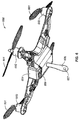
- FIG. 1 illustrates an example UAV 100 that may be used to implement the present invention, in accordance with an embodiment of the present invention.
- the unmanned aerial vehicle 100 can include a propulsion system having one or more rotors 102. Any number of rotors may be provided (e.g., one, two, three, four, five, six, or more).
- the rotors may be configured to be rotatably coupled to respective rotor blades 101. When in use, the rotors can cause the rotor blades to rotate around the rotation mast or shaft at the same or different speed thereby causing the UAV to hover/maintain position, change orientation, and/or change location.
- the distance between shafts of opposite rotors can be any suitable length. For example, the length can be less than or equal to 2 m, or less than equal to 5 m. In some embodiments, the length can be within a range from 40 cm to 1 m, from 10 cm to 2 m, or from 5 cm to 5 m.
- the UAV may include a body 104 that may be used to house or carry various components of the UAV such as electrical components. Such components may be carried inside the body or on the outer surface of the body. Examples of components carried by the body may include flight control units, processors, circuit boards, actuators such as motors, communication units, sensors and the like.
- the body of the UAV may have attached thereto one or more extension members 103.
- the extension members may include a support member that is adapted to support, in whole or in part, weight of the UAV when the UAV is not airborne.
- the support member may include a landing stand such as illustrated in FIG. 1 .
- the landing stand may form a rectangular shape or a similarly shaped structure configured to withstand external forces exerted, for example, during landing.
- the extension members 103 may be configured to be touched, grasped or otherwise contacted by an external object such as a human hand, a robotic arm, and the like.
- an external object such as a human hand, a robotic arm, and the like.
- such contact may be detected by the UAV (e.g., via a touch sensor located on the extension member).
- the UAV may autonomously cause the deceleration of the UAV.
- detected external contact may be received by a controller of the UAV that generates a decelerating signal to one or more actuators (motors) associated with the rotors thereby causing the rotors (and hence associated rotor blades) to slow down, stall and/or come to a complete stop.
- actuators motors
- the UAV may carry onboard one or more sensors 105 and 106.
- the sensors may include but not limit to an inertial sensor, GPS receiver, compass, magnetometer, altimeter, infrared sensor, visual or image sensor (such as a camera or video camera), photo sensor, audio sensor (e.g., microphone), motion detector, touch sensor, pressure sensor, temperature sensor, magnet, and the like.
- the onboard sensors may be located at any suitable locations on the UAV.
- some sensors 105 may be located on the outer surface of the body of the UAV or inside the body.
- some sensors 106 may be located on an extension member coupled to the body of the UAV.
- the onboard sensors may be used for a variety of purposes.
- the sensors may be used for surveillance, surveys, photography, search and rescue, remote sensing, sample collection, scientific research, and the like.
- some of the sensors may be used to facilitate the launching and/or landing of the UAV using techniques described herein.
- the sensors e.g., inertial sensor, GPS receiver and/or visual sensor
- the sensors may be used to detect a positional change of the UAV (including translational or rotational changes such as change in location, velocity, acceleration, and/or orientation).
- the sensors may be used to detect an external signal such as a visual signal, a voice command, a gesture or movement of an object such as a body part.
- an external signal such as a visual signal, a voice command, a gesture or movement of an object such as a body part.
- Such detected positional change and/or external signal may be used to by the UAV as a signal to autonomously start launching the UAV, for example, by causing the start and/or the acceleration of the rotors (and hence the rotation of the rotor blades) to generate the lift necessary to cause the UAV to gain or maintain elevation.
- the launching of the UAV as described above may be based on input from one, two, three or more of the sensors discussed herein.
- the sensors may be used to detect an external contact with the UAV while the UAV is airborne. Based on the detected external contact, the UAV may autonomously cause the deceleration of the rotors (and the associated rotor blades). For example, a controller of the UAV may receive the detected external contact and generate one or more deceleration or stall signals to one or more actuators (e.g., motors) causing the rotor blades to slow down or stop rotating.
- actuators e.g., motors
- positional change and/or external signals such as discussed above may be detected by the UAV and used as signals to engage in the autonomous landing as discussed herein.
- the sensors discussed herein may be located off board. Such sensors may be located in an environment where the UAV operates. For example, the sensors may be mounted on or carried by interior walls of a room (e.g., when the UAV operates indoor), buildings, trees or other fixed structures (e.g., when the UAV operates outdoors), and/or movable objects.
- the movable object may include a vehicle, such as an aerial vehicle, a water vehicle, a ground vehicle, a space vehicle, or any combination thereof. In some embodiments, the movable object can be a living subject, such as a human or an animal.
- a UAV may be capable of engaging in automatic landing operations based on detected external contact with the UAV.
- the UAV may be provided with a holding member or structure configured to be touched, grasped, or otherwise contacted by or engage with an external object.
- a holding member may include a structure that also provides other functionalities.
- the landing leg 103 such as illustrated in FIG. 1 can be configured to be graspable by a human or robotic hand.
- the landing leg is a holding member.
- the landing leg 103 can also be used to support, in whole or in part, the weight of the UAV on a surface when the UAV.
- the holding member can also be used for other purposes (e.g., landing support).
- the holding member may include a structure that is provided for the sole purpose of being contacted by an external object.
- the holding members may include a handle, clasp, rod, rope, leg, stand, structural extension, cavity, hole, bump, magnet, hook, loop, or the like, or any combination thereof.
- FIGs. 2-6 illustrate some example UAVs with such holding members, in accordance with some embodiments.
- the size, shape and dimension of the holding members may be adapted to be held, grasped, gripped or touched by a human hand, a mechanical arm or hand, or any other suitable grasping or gripping device or structure.
- a holding member may be located relative to the UAV such that the holding member is held or touched by a hand or device, there is sufficient distance between the hand or device and the one or more rotor blades of the UAV or any other part of the UAV that may cause injury or damage to hand or device.
- the holding members may include one or more sensors for detecting external contact. Such sensors may include, for example, a touch sensor, temperature sensor, pressure sensor, photo sensor, visual sensor, or any combination thereof. In some embodiments, some or all of such sensors may be embedded in the holding members, located on other portions of the UAV, and/or off of the UAV. The sensors may be configured to communicate with a controller of the UAV using wired or wireless communication methods.
- FIG. 2 illustrates another example UAV 200, in accordance with an embodiment of the present invention.
- the UAV 200 may be similar to the UAV 100 described in connection with FIG. 1 .
- the UAV 200 may include rotors 200, rotor blades 201, body 204, sensors 205 and landing stands 203 that are similar to the corresponding components in the UAV 100 of FIG. 1 .
- the UAV 200 also includes one or more holding rods or handles 206 that may be held or contacted (e.g., by a human hand or a mechanical device) to facilitate the automatic landing discussed herein.
- the holding rods may extend outward or radiate from the side of the body of the UAV.
- the holding members of the UAV may include the holding rods 206 and optionally the landing stands 203.
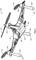
- FIG. 3 illustrates another example UAV 300, in accordance with an embodiment of the present invention.
- the UAV 300 may be similar to the UAVs 100 and 200 described in connection with FIGs. 1-2 .
- the UAV 300 includes one or more substantially vertical holding legs 303 that may be held or contacted (e.g., by a human hand or a mechanical device) to facilitate the automatic landing discussed herein.
- the holding legs 303 may optionally function as landing legs for supporting the weight of the UAV, in whole or in part, on a surface when the UAV is not airborne.
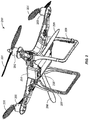
- FIG. 4 illustrates another example UAV 400, in accordance with an embodiment of the present invention.
- the UAV 400 may be similar to the UAV 300 described above in connection with FIG. 3 .
- UAV 400 includes four substantially vertical holding rods 406.
- the holding rods may be held or contacted (e.g., by a human hand or a mechanical device) to facilitate the automatic landing discussed herein.
- Each of the holding rods 406 may include a sensor 407 for detecting external contact with the rod. As discussed above, such a sensor may include a touch sensor, temperature sensor, pressure sensor, photo sensor, visual sensor, or any combination thereof.
- the locations of the holding rods 406 relative to the UAV may be different than those for the holding legs 304.
- the holding rods 406 may be located further apart and/or directly below each of the rotors of the UAV whereas the holding legs 306 may be located closer apart and/or below the body of the UAV.
- the holding rods 406 may optionally function as landing legs for supporting the weight of the UAV, in whole or in part, on a surface when the UAV is not airborne.
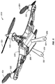
- FIG. 5 illustrates another example UAV 500, in accordance with an embodiment of the present invention.
- the UAV 500 may be similar to the UAV 400 described above in connection with FIG. 4 .
- the UAV 500 may include only two holding rods 506 that extend from the body of the UAV in a bipod fashion.
- Each of the holding rods 506 may include a sensor 507 for detecting external contact with the rod such as discussed above.
- any suitable number of holding rods may be provided.
- the UAV may include one, two, three, four, five or more holding rods.
- FIG. 6 illustrates another example UAV 600, in accordance with an embodiment of the present invention.
- the UAV 600 may be similar to the UAV 500 described above in connection with FIG. 5 .
- the UAV 600 may include only one holding rod 606 that extends substantially perpendicularly from the body of the UAV.
- the holding rod 606 may include a sensor 607 for detecting external contact with the rod such as discussed above.
- a UAV may have any combination of the holding members discussed herein or variations thereof.
- the UAV may have three holding members, two extending from the side of the body of the UAV such as illustrated in FIG. 2 and one extending directly below the body such as illustrated in FIG. 6 .
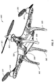
- FIG. 7 illustrates another example of a UAV of the present invention.
- UAV 700 that may be used to implement the present invention, in accordance with an embodiment of the present invention.
- the UAV 700 is similar to the UAV 300 described in connection with FIG. 3 .
- the UAV is also configured to carry a load.
- the load may include a payload 708 and a carrier 709 for the payload.
- the carrier can be integrally formed with the UAV. Alternatively, the carrier can be releasably coupled to the UAV.
- the carrier can include a suitable mounting structure (e.g., a gimbal platform) capable of stabilizing and/or directing the movement of the payload.
- the carrier can be adapted to control the state of the payload (e.g., position and/or orientation) relative to the UAV.
- the carrier can be configured to permit movement of the payload relative to the carrier and/or UAV.
- the movement can be a translation with respect to up to three degrees of freedom (e.g., along one, two, or three axes) or a rotation with respect to up to three degrees of freedom (e.g., about one, two, or three axes), or any suitable combination thereof.
- the carrier can include a frame assembly and an actuation assembly.
- the frame assembly can provide structural support to the payload.
- the frame assembly can include individual frame components, some of which can be movable relative to one another.
- the actuation assembly can include one or more actuators (e.g., motors) that actuate movement of the individual frame components.
- the actuators can permit the movement of multiple frame components simultaneously, or may be configured to permit the movement of a single frame component at a time.
- the movement of the frame components can produce a corresponding movement of the payload.
- an actuation assembly can actuate a rotation of one or more frame components about one or more axes of rotation (e.g., roll axis, pitch axis, or yaw axis).
- the rotation of the one or more frame components can cause a payload to rotate about one or more axes of rotation relative to the UAV.
- the actuation assembly can actuate a translation of one or more frame components along one or more axes of translation, and thereby produce a translation of the payload along one or more corresponding axes relative to the UAV.
- a UAV may be small relative to the load (comprising payload device and/or carrier).
- a ratio of a UAV weight to a load weight may be greater than, less than, or equal to about 1:1.
- a ratio of a UAV weight to a payload weight may be greater than, less than, or equal to about 1:1.
- the a ratio of a UAV weight to a load weight may be 1:2, 1:3, 1:4, or even less.
- the ratio of a UAV weight to a load weight can also be designed to 2:1, 3:1, 4:1, 5:1 or even higher.
- a ratio of a carrier weight to a payload weight may be greater than, less than, or equal to about 1:1.
- the ratio of carrier's weight to payload's weight may 1:2, 1:3, 1:4, or even less. Conversely, the ratio of carrier's weight to payload's weight may 2:1, 3:1, 4:1, 5:1, or even higher.
- the UAV may have low energy consumption. For example, the UAV may use less than 2w/h. In some instances, the carrier may have low energy consumption. For example, the carrier may use less than 2w/h.
Landscapes
- Engineering & Computer Science (AREA)
- Aviation & Aerospace Engineering (AREA)
- Remote Sensing (AREA)
- Automation & Control Theory (AREA)
- Physics & Mathematics (AREA)
- General Physics & Mathematics (AREA)
- Radar, Positioning & Navigation (AREA)
- Mechanical Engineering (AREA)
- Chemical & Material Sciences (AREA)
- Combustion & Propulsion (AREA)
- Microelectronics & Electronic Packaging (AREA)
- Computer Networks & Wireless Communication (AREA)
- Transportation (AREA)
- Toys (AREA)
- Control Of Position, Course, Altitude, Or Attitude Of Moving Bodies (AREA)
Description
- For many years, both amateur and professional operators need to spend many hours of practice and training to master the control of unmanned aerial vehicles (UAVs) including multi-rotor aircraft. In particular, landing and takeoff remain the two most challenging aspects of operating a UAV. Such challenge is exacerbated when encountering uneven surfaces, strong wind, and other environmental factors affecting the operation of the UAV. Therefore, there exists a need for simplified or improved methods, as well as new designs of UAV that would render landing and takeoff easier even for amateur UAV users with little training or practice.
-
US 2013/0253733 A1 discloses one or more rotor blades; a sensor configured to detect a visual signal generated by an operator of said; a controller configured to provide an actuating signal for activating the in response to the detected visual signal; and an actuator configured to cause the one or more rotor blades to move and generate a lift and/or thrust in response to the actuating signal or the visual signal. It further discloses a method for controlling an unmanned aerial vehicle, UAV, in a flight space using a computing device, a 3D sample database is created and store in a storage device of the computing device. The computing device includes a depth-sensing camera that captures a 3D scene image of a scene in front of a user, and senses a depth distance between the user and the depth sensing camera. A 3D person image of the user is detected from the 3D scene image, and gesture information of the user is obtained by comparing the 3D person image with human gesture data stored in the 3D sample database. The method converts the gesture information of the user into one or more flight control commands, and drives a driver of the UAV to control the UAV to fly in a flight space according to the flight control commands. -
US 2009/0222149 A1 discloses a method for controlling at least one remotely operated unmanned object. The method may involve defining a plurality of body movements of an operator that correspond to a plurality of operating commands for the unmanned object. Body movements of the operator may be sensed to generate the operating commands. Wireless signals may be transmitted to the unmanned object that correspond to the operating commands that control operation of the unmanned object. - The present invention addresses this need and provides related advantages as well. The present invention is defined by independent claim 1 defining a method for launching an unmanned rotorcraft, independent claim 4 defining an unmanned aerial vehicle, independent claim7 defining a method for landing an unmanned aerial vehicle and independent claim 11 defining an unmanned aerial vehicle. Embodiments of the claimed invention are defined by the dependent claims.
- In some embodiments, the detection of a visual signal can involve detecting a gesture or movement of a human body.
- In some embodiments, detecting the release of the grip of the UAV by a hand (e.g., a mechanical or a human hand) results in one or more of: setting in motion in an arched trajectory, tossing into the air, catapulting into the air, and retracting or allowing said rotorcraft to fall towards the earth. The release can be effected by releasing any part of the UAV. Depending on the external structural component of the UAV, the release can involve the release of a hook, a rod, a rope, a bump, a hole, a landing leg, a structural extension, or a loop on the UAV. The detection of the release can be performed by one or more of the following sensors including without limitation, a touch sensor, a pressure sensor, a temperature sensor, a photosensor, and a magnet.
- In practicing any of the subject methods for launching a UAV, the detected positional change, visual signal, and/or release of the grip to the UAV may trigger the activating the UAV resulting in a lift and/or thrust. In some embodiments, the lift and/or thrust is generated in less than about 60 seconds, 30 seconds, 10 seconds, 8 seconds, 6 seconds, 5 seconds, 4 seconds, 3 seconds, 2 seconds, 1 second, 0.5 second, 0.1 second, or even 0.01 second upon detecting the said detecting the positional change, visual signal, and/or release of the grip to the UAV. The activation of the UAV may involve activating one or more rotor blades of a UAV. In some embodiments, the activation of the UAV is performed when the UAV reaches a vertical velocity of zero. In some embodiments, upon generating the lift and/or thrust, the UAV hovers over a designated location.
- The UAV of any of the foregoing embodiments can be a rotorcraft including but not limited to the type with multiple rotor blades (multi-rotor aircraft).
- In some embodiments, the sensor for detecting the release of the grip of the UAV by a hand (mechanical or human hand) is a touch sensor, a pressure sensor, a temperature sensor, or any combination thereof.
- In some embodiments, the actuator includes without limitation a DC brushless motor, DC brush motor, and switched reluctance motor. In some embodiments, the actuator is configured to cause the one or more rotor blades to move and generate a lift and/or thrust in less than about 60 seconds, 30 seconds, 10 seconds, 8 seconds, 6 seconds, 5 seconds, 4 seconds, 3 seconds, 2 seconds, 1 second, 0.5 second, 0.1 second, or even 0.01 second, in response to the actuating signal, which is in turn generated when the positional change, visual signal, and/or release of the grip to the UAV is detected.
In some embodiments, the UAV comprises a holding member attached thereto. Such holding member can be a handle, rod, rope, a landing leg, a structural extension, a hook, a loop, or any structural component amendable to be held by a mechanical or human hand. In practicing the method, the external contact can be detected by a sensor selected from the group consisting of a touch sensor, pressure sensor, temperature sensor, photosensor, a magnet, or a combination thereof. For example, the sensor can be configured to detect the external contact exerted by way of capturing said holding member by a hand. Where desired, the method may further comprise determining that the UAV has been captured by a human hand for period of time that exceeds a predetermined threshold value and causing the UAV to come to a stop based on said determination. - In some embodiments, practicing this method utilizes a UAV that is a rotorcraft including one or more rotor blades, and said decelerating causes the one or more rotor blades to slow down, stall, or come to a complete stop. In some embodiments, the decelerating signal effects landing of said UAV at a designated location. The decelerating can include without limitation one or more of the following: causing a decrease in altitude of the UAV, causing a change in attitude of the UAV, causing a reduction in velocity of the UAV, and causing a negative change in acceleration of the UAV. In some instances, the decelerating signal is generated by a controller located in said UAV. In some instances, the decelerating signal is generated in less than about 60 seconds, 30 seconds, 10 seconds, 8 seconds, 6 seconds, 5 seconds, 4 seconds, 3 seconds, 2 seconds, 1 second, 0.5 second, 0.1 second, or even 0.01 second,1 second from detecting said external contact.
- The visual signal being detected includes but is not limited to a gesture or movement of a human body. Where desired, the visual signal can detected by a visual sensor (including but not limited to a camera) located on- or off- board the UAV. In some embodiments, the visual sensor is configured to be in communication with a controller of said UAV, said controller generating the deceleration signal to bring said UAV to a stop.
- In some embodiments, the UAV is brought to a stop in less than about 60 seconds, 30 seconds, 10 seconds, 8 seconds, 6 seconds, 5 seconds, 4 seconds, 3 seconds, 2 seconds, 1 second, 0.5 second, 0.1 second, or even 0.01 second, from detecting said positional change or said visual signal.
- In some instances, the UAV is a rotorcraft including one or more rotor blades, and wherein said decelerating signal causes the one or more rotor blades to slow down, stall, or come to a complete stop.
- Any structural components alone or in combination referenced in the subject methods can be utilized alone or in combination in the subject UAV disclosed herein.
- The novel features of the invention are set forth with particularity in the appended claims. A better understanding of the features and advantages of the present invention will be obtained by reference to the following detailed description that sets forth illustrative embodiments, in which the principles of the invention are utilized, and the accompanying drawings of which:
-
FIG. 1 illustrates an exemplary unmanned aerial vehicle (UAV) that may be used to implement the present invention, in accordance with an embodiment of the present invention. -
FIG. 2 illustrates another exemplary UAV that may be used to implement the present invention, in accordance with an embodiment of the present invention. -
FIG. 3 illustrates another exemplary UAV that may be used to implement the present invention, in accordance with an embodiment of the present invention. -
FIG. 4 illustrates another exemplary UAV that may be used to implement the present invention, in accordance with an embodiment of the present invention. -
FIG. 5 illustrates another exemplary UAV that may be used to implement the present invention, in accordance with an embodiment of the present invention. -
FIG. 6 illustrates another exemplary UAV that may be used to implement the present invention, in accordance with an embodiment of the present invention. -
FIG. 7 illustrates another exemplary UAV that may be used to implement the present invention, in accordance with an embodiment of the present invention. -
FIG. 8 illustrates another exemplary UAV that may be used to implement the present invention, in accordance with an embodiment of the present invention. -
FIG. 9 illustrates another exemplary UAV that may be used to implement the present invention, in accordance with an embodiment of the present invention. -
FIG. 10 illustrates a method for launching a UAV, in accordance with an embodiment of the present invention. -
FIGs. 11A-B illustrate methods for landing a UAV, in accordance with some embodiments of the present invention. -
FIG. 12 illustrates a method for landing a UAV, in accordance with an example which is not part of the present invention. -
FIGs. 13-15 illustrate methods for launching or landing a UAV, in accordance with some embodiment of the present invention. -
FIG. 16 illustrates an exemplary setup utilizing a UAV for implementing the present invention, in accordance with an embodiment. -
FIG. 17 illustrates an exemplary setup utilizing a UAV for implementing the present invention, in accordance with an embodiment. -
FIG. 18 illustrates exemplary components of a system used to implement the present invention, in accordance with an embodiment. - The present invention provides methods and apparatus for launching and landing unmanned aerial vehicle (UAV). According to an aspect of the present invention, simplified methods of launching the UAVs are provided. The subject methods are generally user friendly, designed for automatic launch by even armatures with little training on UAV operation, and thus improving user experience and accessibility. The subject methods can permit taking off and/or landing on uneven surface or rough terrain, thus also accommodating a wide range of environmental conditions conventionally unsuited for UAV operation.
- Accordingly, in one example which is not part of the present invention, a method for launching an unmanned aerial vehicle (UAV), comprises the step of (a) detecting a positional change of the UAV; and (b) in response to the detected positional change, activating the UAV to generate a lift and/or thrust.
- A positional change may include translational changes (e.g., in altitude, latitude and/or longitude) or rotational changes. A positional change may also include changes in the velocity, acceleration, and/or orientation of the UAV. A positional change may further include a change in location of the UAV with respect to a frame of reference or a reference object.
- In some examples which are not part of the present invention, the positional change or positional state may be detected by onboard and/or off-board sensors such as discussed herein. For example, the positional change may be detected by an inertial sensor, GPS receiver, compass, magnetometer, altimeter, proximity sensor (e.g., infrared sensor, LIDAR sensor), visual or image sensor (such as a camera or video camera), photo sensor, motion detector, and the like. For example, an onboard inertial sensor (including one or more gyroscopes and/or accelerometers) may be used to detect a change in acceleration and/or orientation experienced by the UAV. For example, the inertial sensor may be used to detect that the acceleration of the UAV is close to the gravity of the earth indicating that the UAV is experiencing the freefall motion. Similarly, the inertial sensor and/or visual sensor may be used to determine that the vertical velocity of the UAV is close to zero, indicating for example that the UAV is near the vertically highest point of the a parabola-like trajectory. Similarly, an onboard GPS receiver and/or visual sensor may be used to detect a change in the location of the UAV.
- In some examples which are not part of the present invention, detecting the positional change or positional state may include analyzing sensor data obtained from the sensors. Such analysis may be performed by a controller of the UAV, a computer or processor at a remote device or station. In some cases, obtained sensor data may be compared against a threshold and/or predetermined value. In such cases the UAV may utilize a variety of different sensors with built-in threshold limits. The threshold values may include absolute or relative values, depending on the specific positional change to be determined. For example, the threshold value may include the absolute or relative velocity, acceleration, orientation, location coordinates (e.g., altitude, latitude, and/or longitude), and the like. For example, a detected linear acceleration may be compared with the absolute value of g (gravity). As another example, the detected velocity may be compared with the absolute value of zero to determine if the velocity has reached zero, close to zero or has become negative (such as when the UAV has reached or passed the apex of a launching trajectory).
- In some cases, instead of or in addition to comparing sensor data to threshold and/or predetermined values, the obtained sensor data may be compared with previously obtained sensor data. For example, frames of image data obtained from visual sensors may be compared and analyzed to determine changes in velocity and/or location of the UAV since last time the sensor data is obtained and/or the currently velocity and/or location of the UAV.
- Based on the analysis of the sensor data, it may be determined whether the UAV should be activated, started or launched. Such determination may be performed by an onboard controller, a remote computer or processor, or a combination thereof. In response to the determination, an acceleration or activation signal may be generated, for example, by the onboard controller or a remote computer, to actuate one or more rotors of the UAV, thereby causing one or more rotor blades to rotate and generate a suitable lift for the UAV. The generated lift may be sufficient to allow the UAV to maintain an airborne state. In some embodiments, the generated lift allows the UAV to hover over a designated location. In some other embodiments, the generated lift allows the UAV to gain elevation. In yet some other embodiments, the generated lift may also allow the UAV to change its lateral position and/or orientation.
- In some examples which are not part of the present invention, the positional change or positional state may be caused directly by a human.
FIG. 8 illustrates a method for launching a UAV, in accordance with an embodiment of the present invention. As illustrated, aperson 801 throws or tosses aUAV 802 with non-rotating rotor blades into the air in an arc-like trajectory 803. At or near the peak of thetrajectory 803, the vertical velocity of the UAV becomes zero or close to zero. Such zero or near-zero vertical velocity can be detected by an onboard or off-board sensor. In an embodiment, the zero or near-zero vertical velocity may be detected by an inertial sensor and/or visual sensor of theUAV 802. The sensor may provide the detected data to an onboard controller of the UAV or a remote controller, for example, via a wired or wireless link. The controller may determine, in response to the detected positional change or state, the suitable actuation signals to provide to one or more rotors of the UAV. The actuation signals may be generated by an onboard controller, a remote device or a combination thereof. The actuation signals may cause actuation of the one or more rotors, thereby causing rotation ofrespective rotor blades 801 to generate the desired lift 807 sufficient to cause the UAV to become autonomously airborne. For example, UAV may hover over the peak of the trajectory. - In an example which is not part of the present invention, instead of or in addition to the positional change of the UAV discussed above, the release of the UAV by a human hand may be detected.
- Accordingly, in another examples which are not part of the present invention, the present disclosure provides a method for launching an unmanned rotorcraft having (1) one or more rotor blades and (2) at least one sensor being configured to detect release of a grip of said rotorcraft by a hand. The method typically involves the steps of (a) detecting by a sensor on a UAV, the release of the grip by said hand; and (b) in response to the detected release of the grip, generating an activating signal to actuate the one or more rotor blades of the UAV to generate a lift and/or thrust.
- By way of illustration, a UAV may be released by the
person 801 ofFigure 8 via one ormore holding members 810 such as discussed herein. The holding members may be provided with one or more sensors such as touch sensor, pressure sensor, temperature sensor and the like to detect the contact or the lack thereof with the holding members. In an embodiment, the release of the UAV from a mechanical or human hand may be detected by such sensors and in response to the detected release. In response to the detected release of the grip by a mechanical or human hand, an onboard or remote controller of the UAV then generate the actuation signals that cause the activation of the UAV as described herein. - In some embodiments, the actuation signals may be generated within less than about 1 second from the detecting step. In other embodiments, activating signal is generated within a range from as little as about 0.8 seconds, 0.5 seconds, 0.3 seconds, 0.1 seconds, 0.05 seconds, to about .001 second or less from the detecting step. In some instances, activating the one or more rotor blades to generate a lift and/or thrust is performed within less than about 1 second from the detecting step. In other embodiments, activating signal is generated within a range from as little as about 0.8 seconds, 0.5 seconds, 0.3 seconds, 0.1 seconds, 0.05 seconds, to about .001 second or less from the detecting step.
- In some examples which are not part of the present invention, the positional change or positional state may be caused by a mechanical device.
FIG. 9A illustrates an example mechanical device for launching an UAV, in accordance with an embodiment of the present invention. The mechanical device includes amechanical arm 900 that comprises a mechanical hand 906 at one end and anactuator 911 at the other end. The mechanical hand 906 may be configured to hold and/or release a UAV 902. Theactuator 911 may include a mechanical motor, electrical motor, spring assembly or any other suitable actuator. Theactuator 911 may be controlled locally or remotely by a controller or computer. In an embodiment, theactuator 911 may cause the mechanical arm and/or hand to launch the UAV 902 into the air in a similar fashion as the launch by the human hand as discussed above in connection withFIG. 8 . In some examples which are not part of the present invention, the UAV may autonomously start or activate the rotors and rotor blades in response to detected positional change of the UAV and/or detected release of the UAV from the mechanical hand 906, similar to that discussed in connection withFIG. 8 . For example, in response to the detection that the UAV has reached or is about to reach the peak of the trajectory 903 (e.g., detected vertical velocity is or is near zero), and/or the detection that the UAV has been released from the mechanical hand 906 (e.g., via a sensor on the holding member 910), an onboard controller of the UAV may cause one or more rotors to activate thecorresponding rotor blades 901, thereby generating the desired lift and/or thrust 907 that causes the UAV to become autonomously airborne. - Additional methods for launching the UAVs are provided.
Figures 10A-C illustrate another method for launching aUAV 1002, in accordance with an embodiment of the present invention. As illustrated byFIG. 10A , anUAV 1002 is initially held by ahand 1003 of a human 1001. In some embodiments, the UAV may be supported by a human body or a human hand. The UAV may be supported by one or more support members such landing stands or legs. Alternatively, the UAV may be placed directly on the human body or hand without any support members. In some other embodiments, the UAV may be held by the hand via one or more holding members 1005 such as discussed herein. In some examples which are not part of the present invention, rather than being held or supported by a human hand, the UAV may be supported by any other object such as a removable hard surface. In a typical embodiment, when the UAV is thus held or supported, the rotors of the UAV are not actuated and the rotor blades are not moving. - To launch the UAV, as illustrated by
FIG. 10B , the person may withdraw the support of the hand from the UAV or simply drop the UAV from an elevation position. In the cases where the person initially holds the UAV on the palm of a hand, the hand may be withdrawn from underneath the UAV. In the cases where the person initially holds the UAV via a holding member 1005, the holding members may be released, thus releasing the UAV. Regardless of how the UAV is released, acceleration of the UAV typically changes from zero or close to zero to around g (gravity of earth), thus experiencing freefall. Such a change of acceleration may be detected by the UAV, for example, by an inertial sensor. In some embodiments, instead of or in addition to sensing freefall, the UAV may also detect the release of the UAV, for example, by a contact sensor (e.g., touch sensor, pressure sensor, or temperature sensor). In response to the detected positional change and/or release of the UAV, the UAV may spontaneously and autonomously actuate the rotors (and corresponding rotor blades) to generate the desired lift and/orthrust 1035. - As illustrated in
FIG. 10C , the desired lift and/or thrust 1035 may cause the UAV to hover over or gain elevation relative to the location where the UAV was originally held inFIG. 10A . In other embodiments, the post-release altitude of the UAV may be less than the original altitude. Regardless of the post-release position of the UAV, the UAV becomes airborne in an autonomous fashion (i.e., without external support). - In some embodiments, visual sensors may be used to detect external signals for launching the UAV. Accordingly, in a separate example which is not part of the claimed invention , a method for launching a UAV (including an unmanned rotorcraft) having a visual sensor and one or more rotor blades is provided, which method comprises the following steps: (a) detecting, by the rotorcraft, a visual signal generated by an operator of said rotorcraft; and (b) in response to the detected visual signal, activating the one or more rotor blades to generate a lift and/or thrust. As a variant to visual sensor, the method may involve an audio sensor configured to detect a sound signal which can be a command for launching the UAV.
- A wide variety of visual sensors are useful for detecting the external signals for launching the UAV. For example, any visual sensor capable of detecting optical wavelengths within the visible spectrum of a naked eye, infra-red, or ultraviolet wavelength ranges, whether being polarized, high intensity light and/or other types of light wavelengths, are suited for practicing the subject methods. Where desired, the sensor can be a camera or video camera, placed on-board or off-board of the UAV. In some embodiments, some of the onboard sensors may transmit sensor data to an onboard controller, which in turn provides the sensor data to the remote controller. In some other embodiments, some of the onboard sensors may transmit the sensor data directly to the remote control device, e.g., as shown 1720 of
Figure 17 . Various aspects of the sensing and controlling functionalities may be implemented by onboard systems, off-board systems, or a combination thereof. - The external signal being detected is a visual signal, a voice command, a gesture or movement of an object such as a body part.
FIGs. 13-15 illustrate exemplary methods for launching the UAV, in accordance with this embodiment of the present invention. As illustrated inFIG. 13 , agesture 1310 may be detected by anonboard sensor 1305 and used to trigger the launching of the UAV such as discussed herein. The gesture may be made by any body part such as by a hand, arm, head, facial features, eye, and the like. For example, the gesture may include the wave of a hand or arm, the turn of the head, the movement of the eye, and the like. As illustrated byFIG. 14 , a recognizable visual sign, symbol orpattern 1410 may be detected by the onboard sensor 1405 and used to trigger the launching of the UAV. Such predetermined visual sign, symbol or pattern may be of predetermined color, shape, dimension, size and the like. As illustrated inFIG. 15 ,light source 1510 may be detected by anonboard sensor 1505 and used to trigger the launching of the UAV such as discussed herein. Thelight source 1510 may include any light sources so as to provide RGB, UV, NUV, IR, polarized, high intensity light and/or other types of light. The light may be of various wavelengths and modulated in power over time. - The gesture or movement for launching the UAV may include throwing the UAV into the air, releasing or dropping the UAV from an elevated position, or providing predetermined external signals to the UAV, and the like. Such launching methods may be implemented by a human, mechanical device, or a combination thereof. In such examples, various on-board and/or off-board sensors may be used to detect positional changes of the UAV, or external signals (including but not limited to visual signals), or release of a grip of the UAV. Based on the detected changes or signals, an activating signal may be generated, for example, by the onboard controller or a remote computer, to actuate one or more rotors of the UAV, thereby causing one or more rotor blades to rotate and generate a suitable lift for the UAV.
- The generated lift may be sufficient to allow the UAV to maintain an airborne state. In some embodiments, the generated lift allows the UAV to hover over a designated location. In some other embodiments, the generated lift allows the UAV to gain elevation. In yet some other embodiments, the generated lift may also allow the UAV to change its lateral position and/or orientation.
- In a separate aspect, the present invention also provides simplified methods of decelerating a UAV, which can be readily adopted by a UAV user with little or no training on UAV operation. In some embodiments, the deceleration method can effect landing of a UAV at a designated location with little practice by the UAV user.
- Accordingly, in one example which is not part of the present invention, the method of landing a UAV involves the steps of (a) detecting by a sensor on the UAV, an external contact exerted upon said UAV while said UAV is airborne; and (b) generating by said UAV a decelerating signal in response to the detected external contact, thereby decelerating said UAV.
- The contact may be exerted while the UAV is airborne. The external contact may be detected by one or more onboard and/or off-board sensors such as touch sensor, pressure sensor, temperature sensor, photosensor, magnet, visual sensor, or a combination thereof. In response to the detected external contact, one or more decelerating or deactivation signals for causing the rotors to slow down or come to be complete stop. Such signals may be generated by an onboard controller or a remote device. In some embodiments, such signals may cause the UAV to land at a designated location.
- In some embodiments, such external contact may be imposed by a human hand. The person may touch, grasp or otherwise hold a portion of the UAV (e.g., a holding member) while the UAV is airborne. For example, as the UAV hovers near or passes by a person, the person may reach out and get hold of the UAV by hand or by any other suitable device such as a hook, clasp, mechanical arm/hand, or the like. The UAV may detect such contact by an onboard sensor such as those described herein and autonomously slows down or stops the rotors (and hence rotor blades) of the UAV causing the UAV to decelerate or come to a stop.
-
FIG. 9B illustrates an example mechanical device for landing an UAV, in accordance with an embodiment of the present invention. The mechanical device may be similar to that described in connection withFIG. 9A . For example, the mechanical device may include amechanical arm 900, a mechanical hand 906 and anactuator 911. Theactuator 911 may be configured to control the mechanical arm and/or mechanical hand to capture a UAV 902 that is within a predetermined range. For example, the mechanical hand may be controlled grasping or otherwise engaging with one ormore holding members 910 of the UAV so as to capture the UAV. An onboard sensor 905 may be configured to detect the contact of the mechanical hand and as a result, autonomously slows down or stops the rotation of one ormore rotor blades 901. In alternative examples which are not part of the claimed invention, the UAV may be configured to detect contact with other external objects such as a landing surface (e.g., ground or table top) and slows down or stops the UAV in response. - Similarly, the UAV may be configured to detect the contact by a human hand. For example, an onboard temperature sensor may be configured to detect human body temperature on a holding member as a result of a holding of a human hand, thereby triggering the landing of the UAV. In some embodiments, other biometric sensors such as fingerprint sensors may be used to detect human contact.
- In some embodiments, the decelerating or deactivation signals are generated only after the contact is sustained for a predetermined period of time. This may be useful for preventing the UAV from being shut down due to temporary and unintentional external contact. Similarly, in some embodiments, external contact may be used in combination with other sensor input such as positional changes and/or visual signals to determine whether to land the UAV.
- In some embodiments, within less than about 1 second from detecting the external signal, the decelerating signal is generated. In other embodiments, decelerating signal is generated within a range from as little as about 0.8 seconds, 0.5 seconds, 0.3 seconds, 0.1 seconds, 0.05 seconds, to about .001 second or less from the point when the external signal is detected. In some instances, decelerating the UAV is performed within less than about 1 second from the point when the external signal is detected. In other embodiments, decelerating the UAV is performed within a range from as little as about 0.8 seconds, 0.5 seconds, 0.3 seconds, 0.1 seconds, 0.05 seconds, to about .001 second or less from the detecting step.
- In some examples which are not part of the present invention, positional changes may be used to trigger automatic landing of the UAV in addition to or instead of external contact with the UAV. Accordingly, the present disclosure provides a landing method is provided that involves the step of (a) detecting a positional change of the UAV while said UAV is airborne by the UAV; and (b) in response to the detected positional change and/or the visual signal, generating a deceleration signal to said UAV to bring said UAV to a stop.
- Such positional changes may be similar to those discussed in connection with the launching of the UAV. For example, the positional change may include translational changes (e.g., in altitude, latitude and/or longitude) or rotational changes. The positional changes may include changes in the velocity, acceleration, and/or orientation of the UAV. The positional change may also include a change in location with respect to a frame of reference or a reference object. In various examples which are not part of the present invention, the positional change may be detected by an inertial sensor, GPS receiver, compass, magnetometer, altimeter, infrared sensor, visual or image sensor (such as a camera or video camera), photo sensor, motion detector, and the like. In various examples which are not part of the present invention, the positional change may be caused by a human or a mechanical device.
-
FIGs. 11A-B and 12 illustrates exemplary methods for landing an UAV, in accordance with some embodiments. As illustrated inFIG. 11A , an airborne UAV 1102 with rotating rotor blades is caught by a hand of a human 1101 via a holdingmember 1104 of the UAV. In some examples which are not part of the present invention, the mere act of holding the holding member may cause the UAV to decelerate or stop. In some other examples which are not part of the present invention, an additional positional change of the UAV is required besides holding of the UAV. Such an additional positional change may include a change in the orientation of the UAV such as by tilting or turning the UAV by acertain angle 1152 along a particular rotational axis. Such rotational changes may be detected, for example, by an inertial sensor or avisual sensor 1105 of the UAV. - In some examples which are not part of the present invention, the positional change may include a sudden acceleration or deceleration caused by external forces (e.g., human). For example, while holding the UAV, the person may suddenly fling the UAV toward a certain direction causing a sudden acceleration of the UAV. Such acceleration or deceleration may be detected by an onboard sensor such an as an inertial sensor and used to trigger the deceleration of the UAV.
-
FIG. 12 illustrates another example of positional change of the UAV, in accordance with an example which is not part of the present invention. As illustrated, theUAV 1202 is not only held by a human 1201 via a holdingmember 1204 but also moved in apredetermined pattern 1206 such as in a substantially circular pattern, from side to side, in afigure "8 " pattern, or in any other suitable pattern. The movement pattern may be detected by one or more sensors described herein such as inertial sensors, visual sensors, motion sensors and the like. In some examples which are not part of the present invention, the combination of the detected external contact and the detected positional change triggers the slowing down or stopping of the rotor blades of the UAV. - In some examples which are not part of the present invention, external signals may be used to trigger the landing of the UAV in addition to or instead of the external contact and/or positional changes. Such external signals may include visual signals, audio signals, gesture signals or a combination thereof. In one example which is not part of the present invention, a subject landing method involves the steps of: (a) detecting a visual signal generated by an operator of said UAV; and (b) in response to the detected positional change and/or the visual signal, generating a deceleration signal to said UAV to bring said UAV to a stop.
- For example, the methods discussed in connection with
FIGs. 13-15 may be similarly used to land the UAV. As illustrated inFIG. 13 , agesture 1310 may be detected by anonboard sensor 1305 and used to trigger the landing of the UAV such as discussed herein. The gesture may be made by any body part such as by a hand, arm, head, facial features, eye, and the like. As illustrated byFIG. 14 , a recognizable visual sign, symbol orpattern 1410 may be detected by the onboard sensor 1405 and used to trigger the landing of the UAV. Such predetermined visual sign, symbol or pattern may be of predetermined color, shape, dimension, size and the like. As illustrated inFIG. 15 ,light source 1510 may be detected by anonboard sensor 1505 and used to trigger the landing of the UAV such as discussed herein. - In various embodiments, the landing of the UAV may be triggered by the external contact, external signal, any other sensing mechanisms or any combination thereof. For example, as illustrated in
FIGs. 13-15 , the external signals are used in conjunction with detected external contact with the UAV (e.g., the holding of the holdingmember FIGs. 13, 14 or 15 , respectively) to cause the landing of the UAV. As illustrated inFIGs. 11-12 , positional changes are used in conjunction with external contact to trigger the landing of the UAV. In some other embodiments, positional changes may be used in combination with external signals to trigger the landing of the UAV. In some other embodiments, external contact, positional changes and external signals may be used together to trigger the landing of the UAV. - In various embodiments, the sensors and the controllers may be located onboard and/or off-board the UAV. For example, in an embodiment, both the sensors and the controllers are located onboard the UAV. In another embodiment, both the sensors and the controllers can be located off-board the UAV. In some embodiments, some sensors are located onboard the UAV while the other sensors are located off-board the UAV. In another embodiment, some controllers are located onboard the UAV while the other controllers are located off-board the UAV.
- The subject launching and decelerating methods can be implemented by a wide range of UAVs. The subject UAVs exhibit one or more unique features as described herein.
- In one embodiment, the present invention provides an unmanned aerial vehicle (UAV), comprising: (a) one or more rotor blades; (b) a sensor configured to detect a visual signal generated by an operator of said UAV, and a release of a grip by a hand onto said UAV; (c) a controller configured to provide an actuating signal for activating the UAV in response to the visual signal and the release of grip; and (d) an actuator configured to cause the one or more rotor blades to move and generate a lift and/or thrust in response to the actuating signal or the visual signal.
- In another examples which are not part of the present invention, the present invention provides an unmanned aerial vehicle (UAV), comprising: a sensor configured to detect a positional change experienced by the UAV and/or a visual signal generated by an operator of said UAV; a controller configured to provide a deactivating signal for decelerating the UAV in response to the detected positional change and/or the visual signal; and an actuator configured to cause said UAV to decelerate in response to the deactivating signal.
- The present invention further provides a system for implementing a method of launching or decelerating a UAV disclosed here.
FIG. 16 illustrates an exemplary setup. A remote control device 1620, operated by anoperator 1601, is in wireless communication with both onboard sensors 1605 of theUAV 1602 and an off-board sensing system 1630. The off-board sensing system 1630 may include one or more sensors mounted on external structures (fixed or movable) such as a pole, a building, a vehicle, a human or animal, and the like. - In some embodiments, sensor data from the off-board sensing system and/or the onboard sensors may be provided to a remote or off-board controller which may be implemented by the remote control device 1620, remote computer (such as in a base station) or processor, or the like. The remote controller may determine whether to trigger automatic launching or landing of the UAV and may provide the corresponding commands or signals to the UAV as a result. In some other embodiments, sensor data from the off-board sensing system and/or the onboard sensors may be provided to an onboard controller instead of or in addition to the remote controller. In various embodiments, aspects of the controller functionalities discussed herein may be implemented by onboard controllers, off-board controllers or a combination thereof. In some embodiments, autonomous landing is implemented by off-board controllers whereas autonomous launching is implemented by on-board controllers. In some other embodiments, autonomous launching is implemented by off-board controllers whereas autonomous landing is implemented by on-board controllers. In some other embodiments, both autonomous launching and landing are implemented by the onboard controllers. In some other embodiments, both autonomous launching and landing are implemented by the off-board controllers.
-
FIG. 17 illustrates another exemplary setup for implementing the present invention, in accordance with an embodiment. As illustrated, remote control device 1720, operated by anoperator 1701, is in wireless communication with variousonboard sensors UAV 1702. For example, thesensor 1705 may be a positional sensor such as an inertial sensor, GPS receiver, magnetometer, or the like. Thesensor 1730 may be a visual sensor such as a camera or video camera. In some embodiments, some of the onboard sensors may transmit sensor data to an onboard controller, which in turn provides the sensor data to the remote controller. In some other embodiments, some of the onboard sensors may transmit the sensor data directly to the remote control device 1720. As discussed above, various aspects of the sensing and controlling functionalities may be implemented by onboard systems, off-board systems, or a combination thereof. -
FIG. 18 illustrates exemplary components of asystem 1800 used to implement the present invention, in accordance with an embodiment. As illustrated, thesystem 1800 includes acontroller 1810 operatively coupled to one or more sensors or sensing systems 1801a-c via a wired or wireless connection. For example, the sensors may be connected to the controller via a controller area network (CAN). Thecontroller 1810 can also be operatively coupled to one ormore actuators 1820 for controlling the state of the UAV. - The sensors may include any sensors discussed herein, such as inertial sensor, GPS receiver, compass, magnetometer, altimeter, proximity sensor (e.g., infrared sensor or LIDAR sensor), visual or image sensor (such as a camera or video camera), photo sensor, motion detector, touch sensor, pressure sensor, temperature sensor, photosensor, magnetic sensor, and the like.
- In some embodiments, some sensors (such as visual sensors) may be optionally coupled to a field programmable gate array (FPGA, not shown). The FPGA can be operatively coupled to the controller (e.g., via a general purpose memory controller (GPMC) connection). In some embodiments, some sensors (such as visual sensors) and/or the FPGA can be optionally coupled to a transmission module. The transmission module can be used to transmit data captured by the sensors (e.g., image data) to any suitable external device or system, such as a terminal or remote device as described herein.
- The controller can include one or more programmable processors (e.g., a central processing unit (CPU)). The controller can be operatively coupled to a non-transitory computer
readable medium 1830. The non-transitory computer readable medium can include one or more memory units (e.g., removable media or external storage such as an SD card, random access memory (RAM)). In some embodiments, data from the sensors (e.g., camera) can be directly conveyed to and stored within the memory units of the non-transitory computer readable medium (e.g., through a direct memory access (DMA) connection). The memory units of the non-transitory computer readable medium can include code and/or program instructions executable by the controller to perform any suitable embodiment of the methods described herein. For example, the controller can be configured to execute instructions causing one or more processors of the controller to analyze data produced by one or more sensors or sensing systems to determine positional and/or motion information of the UAV, the detected external contact information, and/or the detected external signal information, as described herein. As another example, the controller can be configured to execute instructions causing one or more processors of the controller to determine whether the autonomously launch or land the UAV. - The memory units of the non-transitory computer readable medium 1830 store sensor data from the one or more sensing systems to be processed by the controller. In some embodiments, the memory units of the non-transitory computer readable medium can store the positional and/or motion information of the UAV, the detected external contact information, and/or the detected external signal information. Alternatively or in combination, the memory units of the non-transitory computer readable medium can store predetermined or pre-stored data for controlling the UAV (e.g., predetermined threshold values for sensor data, parameters for controlling the actuators, predetermined flight path, velocity, acceleration or orientation of the UAV).
- As discussed above, the
controller 1810 can be used to adjust the state of the UAV via one ormore actuators 1820. For example, the controller may be used to control the rotors of the UAV (e.g., rotational speed of the rotors) so as to adjust the spatial disposition of the UAV or a component thereof (e.g., a payload, a carrier of the payload) with respect to up to six degrees of freedom (three translational movement (along the X, Y and Z axes) and three rotational movement (along the roll, pitch and yaw axes)). Alternatively or in combination, the controller can be configured to adjust the velocity or acceleration of the UAV with respect to six degrees of freedom. In some embodiments, the controller can control the UAV based on predetermined control data or positional, external contact or external signal information for the UAV obtained by processing data from one or more sensing systems, as described herein. For example, the controller may provide acceleration or deceleration signals to the actuators based on the determination of whether launching or landing is required. - In various embodiments, the actuators can include an electric motor, mechanical actuator, hydraulic actuator, pneumatic actuator, and the like. Electric motors can include magnetic, electrostatic, or piezoelectric motors. For example, in an embodiment, the actuator includes a brushed or brushless DC electric motor.
- The controller can be operatively coupled to a
communication module 1840 configured to transmit and/or receive data from one or more external devices (e.g., a terminal, display device, or other remote controller). Any suitable means of communication can be used, such as wired communication or wireless communication. For example, the communication module can utilize one or more of local area networks (LAN), wide area networks (WAN), infrared, radio, WiFi, peer-to-peer (P2P) networks, telecommunication networks, cloud communication, and the like. Optionally, relay stations, such as towers, satellites, or mobile stations, can be used. Wireless communications can be proximity dependent or proximity independent. In some embodiments, line-of-sight may or may not be required for communications. The communication module can transmit and/or receive one or more of sensor data from the sensing systems, positional and/or motion information, external contact information and/or external signal information determined by processing the sensor data, predetermined control data, user commands from a terminal or remote controller, and the like. - The components of the system can be arranged in any suitable configuration. For example, one or more of the components of the system can be located on the UAV, carrier, payload, terminal, sensing system, or any other remote device or system in communication with one or more of the above. Additionally, although
FIG. 18 depicts a single controller and a single non-transitory computer readable medium, one of skill in the art would appreciate that this is not intended to be limiting, and that the system can include a plurality of controllers and/or non-transitory computer readable media. In some embodiments, one or more of the plurality of controllers and/or non-transitory computer readable media can be situated at different locations, such as on the UAV, carrier, payload, terminal, sensing system, or any other remote device or system in communication with one or more of the above, or suitable combinations thereof, such that any suitable aspect of the processing and/or memory functions performed by the system can occur at one or more of the aforementioned locations. - The subject UAVs, alone or for operation in the context of a system as disclosed herein, include without limitation single-rotor aircraft, multi-rotor aircraft, and rotary-wing aircraft. Rotary-wing aircraft typically utilizes lift generated by rotor blades, which revolve around a mast or shaft. Examples of such rotorcrafts may include helicopters, cyclocopters, autogyros, gyrodynes, and the like. Such rotorcrafts may have more than one rotor fixed about the craft in more than one location. For example, the subject UAVs may include quadcopters, hexacopters, octocopters, and the like.
- In various embodiments, the UAVs may move freely with respect to up to six degrees of freedom (e.g., three degrees of freedom in translation and three degrees of freedom in rotation). Alternatively, the movement of the UAV may be constrained with respect to one or more degrees of freedom, such as by a predetermined path or track. The movement can be actuated by any suitable actuation mechanism, such as an engine or a motor. In some embodiments, the UAV may be driven by a propulsion system. Examples of propulsion systems may include engines, motors, wheels, axles, magnets, rotors, propellers, blades, nozzles, or any suitable combination thereof. The movement of the UAV may be powered by any suitable energy source, such as electrical energy, magnetic energy, solar energy, wind energy, gravitational energy, chemical energy, nuclear energy, or any suitable combination thereof.
- In various embodiments, the subject UAVs may adopt different sizes, dimensions and/or configurations. For example, in an embodiment, the subject UAVs may be multi-rotor UAVs where the distance between the shafts of opposing rotors does not exceed a certain threshold value. Such threshold value may be around 5 meters, 4 meters, 3, meters, 2 meters, 1 meter, or the like. For instances, the values of the distance between shafts of opposing rotors may be 350 millimeters, 450 millimeters, 800 millimeters, 900 millimeters and the like.
- In some embodiments, the UAV may be of a size and/or dimensions sufficient to accommodate a human occupant within or on the UAV. Alternatively, the UAV may be of size and/or dimensions smaller than that capable of having a human occupant within or on the UAV. In some instances, the UAV may have a maximum dimension (e.g., length, width, height, diameter, diagonal) of no more than 5m, 4m, 3m, 2m, 1m, 0.5m, or 0.1m. For example, the distance between shafts of opposing rotors may be no more than 5 m, 4m, 3m, 2m, 1m, 0.5m, or 0.1m. In some embodiments, the UAV may have a volume of less than 100cm x 100cm x 100 cm. In some embodiments, the UAV may have a volume of less than 50cm x 50cm x 30 cm. In some embodiments, the UAV may have a volume of less than 5cm x 5cm x 3 cm. In some embodiments, the UAV may have a footprint (which may refer to the lateral cross-sectional area encompassed by the UAV) less than about 32,000 cm2, less than about 20,000 cm2, less than about10,000 cm2, less than about1,000 cm2, less than about 500 cm2, less than about 100 cm2 or even less. In some instances, the UAV may weigh no more than1000 kg, no more than 500 kg, no more than100 kg , no more than10 kg, no more than 5 kg, no more than 1 kg, or no more than 0.5 kg.
- In various embodiments, the UAV may be configured to carry a load. The load can include one or more of cargo, equipment, instruments, and the like. The load can be provided within a housing. Alternatively, portions of the load or the entire load can be provided without a housing. The load can be rigidly fixed relative to the UAV. Alternatively, the load can be movable relative to the UAV (e.g., translatable or rotatable relative to the UAV).
- In some embodiments, the load includes a payload 708 and a
carrier 709 for the payload. The carrier can be integrally formed with the UAV. Alternatively, the carrier can be releasably coupled to the UAV. The carrier can be coupled to the UAV directly or indirectly. The carrier can provide support to the payload (e.g., carry at least part of the weight of the payload). The carrier can include a suitable mounting structure (e.g., a gimbal platform) capable of stabilizing and/or directing the movement of the payload. In some embodiments, the carrier can be adapted to control the state of the payload (e.g., position and/or orientation) relative to the UAV. For example, the carrier can be configured to move relative to the UAV (e.g., with respect to one, two, or three degrees of translation and/or one, two, or three degrees of rotation) such that the payload maintains its position and/or orientation relative to a suitable reference frame regardless of the movement of the UAV. The reference frame can be a fixed reference frame (e.g., the surrounding environment). Alternatively, the reference frame can be a moving reference frame (e.g., the UAV, a payload target). - In some embodiments, the carrier can be configured to permit movement of the payload relative to the carrier and/or UAV. The movement can be a translation with respect to up to three degrees of freedom (e.g., along one, two, or three axes) or a rotation with respect to up to three degrees of freedom (e.g., about one, two, or three axes), or any suitable combination thereof. For example, the carrier can include a frame assembly and an actuation assembly. The frame assembly can provide structural support to the payload. The frame assembly can include individual frame components, some of which can be movable relative to one another.
- The frame assembly and/or its individual components can be coupled to an actuation assembly that faciliates the movement of the frame assembly. The actuation assembly can include one or more actuators (e.g., motors) that actuate movement of the individual frame components. The actuators can permit the movement of multiple frame components simultaneously, or may be configured to permit the movement of a single frame component one at a time. The movement of the frame components can produce a corresponding movement of the payload. For example, the actuation assembly can actuate a rotation of one or more frame components about one or more axes of rotation (e.g., roll axis, pitch axis, or yaw axis). The rotation of the one or more frame components can cause a payload to rotate about one or more axes of rotation relative to the UAV. Alternatively or in combination, the actuation assembly can actuate a translation of one or more frame components along one or more axes of translation, and thereby produce a translation of the payload along one or more corresponding axes relative to the UAV.
- The payload can be coupled to the UAV via the carrier, either directly (e.g., directly contacting the UAV) or indirectly (e.g., not contacting the UAV). Optionally, the payload can be mounted on the UAV without requiring a carrier. The payload can be integrally formed with the carrier. Alternatively, the payload can be releasably coupled to the carrier. In some embodiments, the payload can include one or more payload elements, and one or more of the payload elements can be movable relative to the UAV and/or the carrier, as described above. The payload can include one or more sensors for surveying one or more targets. Any suitable sensor can be incorporated into the payload, such as an image capture device (e.g., a camera), an audio capture device (e.g., a parabolic microphone), an infrared imaging device, or an ultraviolet imaging device. The sensor can provide static sensor data (e.g., a photograph) or dynamic sensor data (e.g., a video). In some embodiments, the sensor provides sensor data for the target of the payload. Alternatively or in combination, the payload can include one or more emitters for providing signals to one or more targets. Any suitable emitter can be used, such as an illumination source or a sound source. In some embodiments, the payload includes one or more transceivers, such as for communication with a module remote from the UAV.
-
FIG. 1 illustrates anexample UAV 100 that may be used to implement the present invention, in accordance with an embodiment of the present invention. The unmannedaerial vehicle 100 can include a propulsion system having one or more rotors 102. Any number of rotors may be provided (e.g., one, two, three, four, five, six, or more). The rotors may be configured to be rotatably coupled to respective rotor blades 101. When in use, the rotors can cause the rotor blades to rotate around the rotation mast or shaft at the same or different speed thereby causing the UAV to hover/maintain position, change orientation, and/or change location. The distance between shafts of opposite rotors can be any suitable length. For example, the length can be less than or equal to 2 m, or less than equal to 5 m. In some embodiments, the length can be within a range from 40 cm to 1 m, from 10 cm to 2 m, or from 5 cm to 5 m. - In some embodiments, the UAV may include a body 104 that may be used to house or carry various components of the UAV such as electrical components. Such components may be carried inside the body or on the outer surface of the body. Examples of components carried by the body may include flight control units, processors, circuit boards, actuators such as motors, communication units, sensors and the like.
- In some embodiment, the body of the UAV may have attached thereto one or
more extension members 103. The extension members may include a support member that is adapted to support, in whole or in part, weight of the UAV when the UAV is not airborne. For example, the support member may include a landing stand such as illustrated inFIG. 1 . The landing stand may form a rectangular shape or a similarly shaped structure configured to withstand external forces exerted, for example, during landing. - In some embodiments, the
extension members 103 may be configured to be touched, grasped or otherwise contacted by an external object such as a human hand, a robotic arm, and the like. In some embodiments, such contact may be detected by the UAV (e.g., via a touch sensor located on the extension member). In response to the detected external contact, the UAV may autonomously cause the deceleration of the UAV. For example, detected external contact may be received by a controller of the UAV that generates a decelerating signal to one or more actuators (motors) associated with the rotors thereby causing the rotors (and hence associated rotor blades) to slow down, stall and/or come to a complete stop. - In various embodiments, the UAV may carry onboard one or
more sensors 105 and 106. Examples of the sensors may include but not limit to an inertial sensor, GPS receiver, compass, magnetometer, altimeter, infrared sensor, visual or image sensor (such as a camera or video camera), photo sensor, audio sensor (e.g., microphone), motion detector, touch sensor, pressure sensor, temperature sensor, magnet, and the like. - In various embodiments, the onboard sensors may be located at any suitable locations on the UAV. For example, some
sensors 105 may be located on the outer surface of the body of the UAV or inside the body. As another example, some sensors 106 may be located on an extension member coupled to the body of the UAV. - The onboard sensors may be used for a variety of purposes. For example, the sensors may be used for surveillance, surveys, photography, search and rescue, remote sensing, sample collection, scientific research, and the like. In some embodiments, some of the sensors may be used to facilitate the launching and/or landing of the UAV using techniques described herein. For example, the sensors (e.g., inertial sensor, GPS receiver and/or visual sensor) may be used to detect a positional change of the UAV (including translational or rotational changes such as change in location, velocity, acceleration, and/or orientation). As another example, the sensors (e.g., visual sensor, audio sensor, or motion detector) may be used to detect an external signal such as a visual signal, a voice command, a gesture or movement of an object such as a body part. Such detected positional change and/or external signal may be used to by the UAV as a signal to autonomously start launching the UAV, for example, by causing the start and/or the acceleration of the rotors (and hence the rotation of the rotor blades) to generate the lift necessary to cause the UAV to gain or maintain elevation. In some embodiments, the launching of the UAV as described above may be based on input from one, two, three or more of the sensors discussed herein.
- As another example, the sensors (e.g., touch sensor, pressure sensor, photo sensor, motion sensor) may be used to detect an external contact with the UAV while the UAV is airborne. Based on the detected external contact, the UAV may autonomously cause the deceleration of the rotors (and the associated rotor blades). For example, a controller of the UAV may receive the detected external contact and generate one or more deceleration or stall signals to one or more actuators (e.g., motors) causing the rotor blades to slow down or stop rotating. Instead of or in addition to external contact, positional change and/or external signals (audio/visual/movement) such as discussed above may be detected by the UAV and used as signals to engage in the autonomous landing as discussed herein.
- In some embodiments, some or all of the sensors discussed herein may be located off board. Such sensors may be located in an environment where the UAV operates. For example, the sensors may be mounted on or carried by interior walls of a room (e.g., when the UAV operates indoor), buildings, trees or other fixed structures (e.g., when the UAV operates outdoors), and/or movable objects. The movable object may include a vehicle, such as an aerial vehicle, a water vehicle, a ground vehicle, a space vehicle, or any combination thereof. In some embodiments, the movable object can be a living subject, such as a human or an animal.
- As discussed above, a UAV may be capable of engaging in automatic landing operations based on detected external contact with the UAV. To facilitate such external contact, in some embodiments, the UAV may be provided with a holding member or structure configured to be touched, grasped, or otherwise contacted by or engage with an external object. In some embodiments, such a holding member may include a structure that also provides other functionalities. For example, the
landing leg 103 such as illustrated inFIG. 1 can be configured to be graspable by a human or robotic hand. In other words, the landing leg is a holding member. At the same time, thelanding leg 103 can also be used to support, in whole or in part, the weight of the UAV on a surface when the UAV. Thus, the holding member can also be used for other purposes (e.g., landing support). In other embodiments, the holding member may include a structure that is provided for the sole purpose of being contacted by an external object. - In various embodiments, the holding members may include a handle, clasp, rod, rope, leg, stand, structural extension, cavity, hole, bump, magnet, hook, loop, or the like, or any combination thereof.
FIGs. 2-6 illustrate some example UAVs with such holding members, in accordance with some embodiments. In some embodiments, the size, shape and dimension of the holding members may be adapted to be held, grasped, gripped or touched by a human hand, a mechanical arm or hand, or any other suitable grasping or gripping device or structure. In some embodiments, a holding member may be located relative to the UAV such that the holding member is held or touched by a hand or device, there is sufficient distance between the hand or device and the one or more rotor blades of the UAV or any other part of the UAV that may cause injury or damage to hand or device. In some embodiments, the holding members may include one or more sensors for detecting external contact. Such sensors may include, for example, a touch sensor, temperature sensor, pressure sensor, photo sensor, visual sensor, or any combination thereof. In some embodiments, some or all of such sensors may be embedded in the holding members, located on other portions of the UAV, and/or off of the UAV. The sensors may be configured to communicate with a controller of the UAV using wired or wireless communication methods. -
FIG. 2 illustrates anotherexample UAV 200, in accordance with an embodiment of the present invention. TheUAV 200 may be similar to theUAV 100 described in connection withFIG. 1 . For example, theUAV 200 may includerotors 200,rotor blades 201,body 204,sensors 205 and landing stands 203 that are similar to the corresponding components in theUAV 100 ofFIG. 1 . However, unlike theUAV 100, theUAV 200 also includes one or more holding rods or handles 206 that may be held or contacted (e.g., by a human hand or a mechanical device) to facilitate the automatic landing discussed herein. The holding rods may extend outward or radiate from the side of the body of the UAV. The holding members of the UAV may include the holdingrods 206 and optionally the landing stands 203. -
FIG. 3 illustrates anotherexample UAV 300, in accordance with an embodiment of the present invention. TheUAV 300 may be similar to theUAVs FIGs. 1-2 . However, instead of landing stands 203 or holdingrods 206, theUAV 300 includes one or more substantially vertical holdinglegs 303 that may be held or contacted (e.g., by a human hand or a mechanical device) to facilitate the automatic landing discussed herein. In some embodiments, the holdinglegs 303 may optionally function as landing legs for supporting the weight of the UAV, in whole or in part, on a surface when the UAV is not airborne. -
FIG. 4 illustrates anotherexample UAV 400, in accordance with an embodiment of the present invention. TheUAV 400 may be similar to theUAV 300 described above in connection withFIG. 3 . For example,UAV 400 includes four substantially vertical holdingrods 406. The holding rods may be held or contacted (e.g., by a human hand or a mechanical device) to facilitate the automatic landing discussed herein. Each of the holdingrods 406 may include asensor 407 for detecting external contact with the rod. As discussed above, such a sensor may include a touch sensor, temperature sensor, pressure sensor, photo sensor, visual sensor, or any combination thereof. Furthermore, the locations of the holdingrods 406 relative to the UAV may be different than those for the holdinglegs 304. For example, the holdingrods 406 may be located further apart and/or directly below each of the rotors of the UAV whereas the holdinglegs 306 may be located closer apart and/or below the body of the UAV. In some embodiments, the holdingrods 406 may optionally function as landing legs for supporting the weight of the UAV, in whole or in part, on a surface when the UAV is not airborne. -
FIG. 5 illustrates anotherexample UAV 500, in accordance with an embodiment of the present invention. TheUAV 500 may be similar to theUAV 400 described above in connection withFIG. 4 . However, instead of four substantially vertical holding rods, theUAV 500 may include only two holdingrods 506 that extend from the body of the UAV in a bipod fashion. Each of the holdingrods 506 may include asensor 507 for detecting external contact with the rod such as discussed above. In some embodiments, any suitable number of holding rods may be provided. For example, the UAV may include one, two, three, four, five or more holding rods. -
FIG. 6 illustrates another example UAV 600, in accordance with an embodiment of the present invention. The UAV 600 may be similar to theUAV 500 described above in connection withFIG. 5 . However, instead of two bipod-like holding rods, the UAV 600 may include only one holding rod 606 that extends substantially perpendicularly from the body of the UAV. The holding rod 606 may include asensor 607 for detecting external contact with the rod such as discussed above. In various embodiments, a UAV may have any combination of the holding members discussed herein or variations thereof. For example, in an embodiment, the UAV may have three holding members, two extending from the side of the body of the UAV such as illustrated inFIG. 2 and one extending directly below the body such as illustrated inFIG. 6 . -
FIG. 7 illustrates another example of a UAV of the present invention. UAV 700 that may be used to implement the present invention, in accordance with an embodiment of the present invention. The UAV 700 is similar to theUAV 300 described in connection withFIG. 3 . However, as illustrated, the UAV is also configured to carry a load. The load may include a payload 708 and acarrier 709 for the payload. The carrier can be integrally formed with the UAV. Alternatively, the carrier can be releasably coupled to the UAV. The carrier can include a suitable mounting structure (e.g., a gimbal platform) capable of stabilizing and/or directing the movement of the payload. In some embodiments, the carrier can be adapted to control the state of the payload (e.g., position and/or orientation) relative to the UAV. In some embodiments, the carrier can be configured to permit movement of the payload relative to the carrier and/or UAV. The movement can be a translation with respect to up to three degrees of freedom (e.g., along one, two, or three axes) or a rotation with respect to up to three degrees of freedom (e.g., about one, two, or three axes), or any suitable combination thereof. For example, the carrier can include a frame assembly and an actuation assembly. The frame assembly can provide structural support to the payload. The frame assembly can include individual frame components, some of which can be movable relative to one another. The actuation assembly can include one or more actuators (e.g., motors) that actuate movement of the individual frame components. The actuators can permit the movement of multiple frame components simultaneously, or may be configured to permit the movement of a single frame component at a time. The movement of the frame components can produce a corresponding movement of the payload. For example, an actuation assembly can actuate a rotation of one or more frame components about one or more axes of rotation (e.g., roll axis, pitch axis, or yaw axis). The rotation of the one or more frame components can cause a payload to rotate about one or more axes of rotation relative to the UAV. Alternatively or in combination, the actuation assembly can actuate a translation of one or more frame components along one or more axes of translation, and thereby produce a translation of the payload along one or more corresponding axes relative to the UAV. - In some embodiments, a UAV may be small relative to the load (comprising payload device and/or carrier). In some examples, a ratio of a UAV weight to a load weight may be greater than, less than, or equal to about 1:1. In some instances, a ratio of a UAV weight to a payload weight may be greater than, less than, or equal to about 1:1. Where desired, the a ratio of a UAV weight to a load weight may be 1:2, 1:3, 1:4, or even less. Conversely, the ratio of a UAV weight to a load weight can also be designed to 2:1, 3:1, 4:1, 5:1 or even higher. Optionally, a ratio of a carrier weight to a payload weight may be greater than, less than, or equal to about 1:1. Where desired, the ratio of carrier's weight to payload's weight may 1:2, 1:3, 1:4, or even less. Conversely, the ratio of carrier's weight to payload's weight may 2:1, 3:1, 4:1, 5:1, or even higher. In some embodiments, the UAV may have low energy consumption. For example, the UAV may use less than 2w/h. In some instances, the carrier may have low energy consumption. For example, the carrier may use less than 2w/h.
Claims (15)
- A method for launching an unmanned rotorcraft (1002, 902, 802) comprising a visual sensor (1305, 1405, 1505, 1705) and one or more rotor blades (201, 801, 901), said method comprising:(a) detecting, by the rotorcraft (1002, 902, 802), a visual signal (1310, 1410, 1510) generated by an operator (1001, 1301, 1401, 1501, 1601) of said rotorcraft (1002, 902, 802); and(b) detecting a release of grip of the unmanned rotorcraft (1002, 902, 802) by a hand (906, 1003); and(c) in response to the detected visual signal (1310, 1410, 1510) and the release of grip of the unmanned rotorcraft, activating the one or more rotor blades (201, 801, 901) to generate a lift and/or thrust.
- The method of claim 1, wherein the generating the lift and/or thrust is effectuated by an on-board controller (1810) configured to be in communication with said sensor (1305, 1405, 1505, 1705).
- The method of claim 1, wherein the visual signal (1310, 1410, 1510) includes a gesture or movement of a human body (1310, 1410, 1510).
- An unmanned aerial vehicle (UAV) (1002, 902, 802), comprising(a) one or more rotor blades (201, 801, 901);(b) a sensor (1305, 1405, 1505, 1705) configured to detect a visual signal (1310, 1410, 1510) generated by an operator (1001, 1301, 1401, 1501, 1601) of said UAV (1002, 902, 802);(c) a sensor configured to detect a release of grip of the UAV (1002, 902, 802);(d) a controller (1810) configured to provide an actuating signal for activating the UAV (1002, 902, 802) in response to the detected visual signal (1310, 1410, 1510) and the detected release of grip; and(e) an actuator (911, 1820) configured to cause the one or more rotor blades (201, 801, 901) to move and generate a lift and/or thrust in response to the actuating signal..
- The UAV (1002, 902, 802) of claim 4, wherein the sensor (1305, 1405, 1505, 1705) is a visual sensor, a photosensor, a camera located on board of said UAV (1002, 902, 802) or an off -board camera configured to be in communication with said UAV (1002, 902, 802).
- The UAV (1002, 902, 802) of claim 4, wherein the controller (1810) is configured to be in communication with the sensor and to provide said actuating signal in response to the detected visual signal (1310, 1410, 1510).
- A method for landing an unmanned aerial vehicle (UAV) (1002, 902, 802), comprising:(a) detecting a visual signal (1310, 1410, 1510) generated by an operator (1001, 1301, 1401, 1501, 1601) of said UAV (1002, 902, 802); and(b) detecting a contact by a hand; and(c) in response to the detected visual signal (1310, 1410, 1510) and when the detected contact is sustained for a predetermined period of time, generating a deceleration signal to said UAV (1002, 902, 802) to bring said UAV (1002, 902, 802) to a stop.
- The method of claim 7, wherein the visual signal (1310, 1410, 1510) includes a gesture or movement of a human body (1310, 1410, 1510).
- The method of claim 7, wherein the visual signal (1310, 1410, 1510) is detected by a visual sensor (1305, 1405, 1505, 1705) located on-or off- board the UAV (1002, 902, 802).
- The method of claim 9, wherein the visual sensor (1305, 1405, 1505, 1705) is configured to be in communication with a controller (1810) of said UAV (1002, 902, 802), said controller (1810) generating the deceleration signal to bring said UAV (1002, 902, 802) to a stop.
- An unmanned aerial vehicle (UAV) (1002, 902, 802), comprising
a sensor configured to detect a visual signal (1310, 1410, 1510) generated by an operator (1001, 1301, 1401, 1501, 1601) of said UAV (1002, 902, 802);
a sensor configured to detect a contact by a hand;
a controller (1810) configured to provide a deactivating signal for decelerating the UAV (1002, 902, 802) in response to the detected visual signal (1310, 1410, 1510) and when the detected contact is sustained over a predetermined period of time; and
an actuator (911, 1820) configured to cause said UAV (1002, 902, 802) to decelerate in response to the deactivating signal. - The UAV (1002, 902, 802) of claim 11, wherein the sensor (1305, 1405, 1505, 1705) is a visual sensor (1305, 1405, 1505, 1705).
- The UAV (1002, 902, 802) of claim 11, wherein the UAV (1002, 902, 802) is a rotorcraft including one or more rotor blades (201, 801, 901), and wherein said decelerating signal causes the one or more rotor blades (201, 801, 901) to slow down, stall, or come to a complete stop.
- The UAV (1002, 902, 802) of claim 11, wherein the visual sensor (1305, 1405, 1505, 1705) is configured to be in communication with said controller (1810) to effect providing said deactivating signal for decelerating the UAV (1002, 902, 802) in response to the detected visual signal (1310, 1410, 1510).
- The UAV (1002, 902, 802) of claim 11, wherein the visual signal (1310, 1410, 1510) is a gesture of a human operator (1310, 1410, 1510).
Priority Applications (1)
| Application Number | Priority Date | Filing Date | Title |
|---|---|---|---|
| EP19176060.2A EP3552955B1 (en) | 2013-12-13 | 2013-12-13 | Methods for launching and landing an unmanned aerial vehicle |
Applications Claiming Priority (4)
| Application Number | Priority Date | Filing Date | Title |
|---|---|---|---|
| EP19176060.2A EP3552955B1 (en) | 2013-12-13 | 2013-12-13 | Methods for launching and landing an unmanned aerial vehicle |
| PCT/CN2013/089443 WO2015085598A1 (en) | 2013-12-13 | 2013-12-13 | Methods for launching and landing an unmanned aerial vehicle |
| EP17204685.6A EP3323715B1 (en) | 2013-12-13 | 2013-12-13 | Method for landing an unmanned aerial vehicle |
| EP13828971.5A EP2906468B1 (en) | 2013-12-13 | 2013-12-13 | Methods for launching an unmanned aerial vehicle |
Related Parent Applications (3)
| Application Number | Title | Priority Date | Filing Date |
|---|---|---|---|
| EP17204685.6A Division EP3323715B1 (en) | 2013-12-13 | 2013-12-13 | Method for landing an unmanned aerial vehicle |
| EP17204685.6A Division-Into EP3323715B1 (en) | 2013-12-13 | 2013-12-13 | Method for landing an unmanned aerial vehicle |
| EP13828971.5A Division EP2906468B1 (en) | 2013-12-13 | 2013-12-13 | Methods for launching an unmanned aerial vehicle |
Publications (2)
| Publication Number | Publication Date |
|---|---|
| EP3552955A1 EP3552955A1 (en) | 2019-10-16 |
| EP3552955B1 true EP3552955B1 (en) | 2021-07-14 |
Family
ID=53318762
Family Applications (3)
| Application Number | Title | Priority Date | Filing Date |
|---|---|---|---|
| EP17204685.6A Active EP3323715B1 (en) | 2013-12-13 | 2013-12-13 | Method for landing an unmanned aerial vehicle |
| EP13828971.5A Active EP2906468B1 (en) | 2013-12-13 | 2013-12-13 | Methods for launching an unmanned aerial vehicle |
| EP19176060.2A Active EP3552955B1 (en) | 2013-12-13 | 2013-12-13 | Methods for launching and landing an unmanned aerial vehicle |
Family Applications Before (2)
| Application Number | Title | Priority Date | Filing Date |
|---|---|---|---|
| EP17204685.6A Active EP3323715B1 (en) | 2013-12-13 | 2013-12-13 | Method for landing an unmanned aerial vehicle |
| EP13828971.5A Active EP2906468B1 (en) | 2013-12-13 | 2013-12-13 | Methods for launching an unmanned aerial vehicle |
Country Status (5)
| Country | Link |
|---|---|
| US (5) | US9696725B2 (en) |
| EP (3) | EP3323715B1 (en) |
| JP (1) | JP6366730B2 (en) |
| CN (1) | CN104685436B (en) |
| WO (1) | WO2015085598A1 (en) |
Families Citing this family (154)
| Publication number | Priority date | Publication date | Assignee | Title |
|---|---|---|---|---|
| US9384668B2 (en) | 2012-05-09 | 2016-07-05 | Singularity University | Transportation using network of unmanned aerial vehicles |
| US20150286216A1 (en) * | 2012-10-31 | 2015-10-08 | The University Of Tokushima | Conveyance device and control method for flight vehicle |
| US9696725B2 (en) | 2013-12-13 | 2017-07-04 | SZ DJI Technology Co., Ltd | Methods for launching and landing an unmanned aerial vehicle |
| EP3537104B1 (en) * | 2014-04-25 | 2021-06-02 | Sony Corporation | Information processing device, information processing method, and computer program |
| CN106458318A (en) * | 2014-05-23 | 2017-02-22 | 莉莉机器人公司 | Unmanned aerial photography helicopter for photography and/or video |
| FR3025114A1 (en) * | 2014-08-26 | 2016-03-04 | Parrot | DYNAMIC START CONTROL METHOD LAUNCHING ROTARY SAIL DRONE |
| US20160124435A1 (en) * | 2014-10-29 | 2016-05-05 | Lyle Thompson | 3d scanning and imaging method utilizing a self-actuating compact unmanned aerial device |
| JP6556847B2 (en) * | 2014-12-31 | 2019-08-07 | エスゼット ディージェイアイ テクノロジー カンパニー リミテッドSz Dji Technology Co.,Ltd | Moving object and antenna automatic alignment method thereof |
| US10220954B2 (en) | 2015-01-04 | 2019-03-05 | Zero Zero Robotics Inc | Aerial system thermal control system and method |
| US10358214B2 (en) | 2015-01-04 | 2019-07-23 | Hangzhou Zero Zro Technology Co., Ltd. | Aerial vehicle and method of operation |
| US10719080B2 (en) | 2015-01-04 | 2020-07-21 | Hangzhou Zero Zero Technology Co., Ltd. | Aerial system and detachable housing |
| CN104991561B (en) * | 2015-08-10 | 2019-02-01 | 北京零零无限科技有限公司 | A kind of method, apparatus and unmanned plane of hand-held unmanned plane recycling |
| US9836053B2 (en) | 2015-01-04 | 2017-12-05 | Zero Zero Robotics Inc. | System and method for automated aerial system operation |
| CN105182986A (en) * | 2015-08-10 | 2015-12-23 | 北京零零无限科技有限公司 | Method of retrieving and releasing unmanned aerial vehicle in hand-held mode and apparatus thereof |
| US10126745B2 (en) | 2015-01-04 | 2018-11-13 | Hangzhou Zero Zero Technology Co., Ltd. | System and method for automated aerial system operation |
| CN105116909A (en) * | 2015-08-10 | 2015-12-02 | 北京零零无限科技有限公司 | Method of releasing unmanned aerial vehicle in hand-held mode, apparatus and the unmanned aerial vehicle |
| NZ738804A (en) | 2015-07-06 | 2022-08-26 | Zero Co Ltd | Rotorcraft landing device |
| JP6709690B2 (en) * | 2015-07-17 | 2020-06-17 | パナソニック インテレクチュアル プロパティ コーポレーション オブ アメリカPanasonic Intellectual Property Corporation of America | Unmanned aerial vehicle, flight control method and flight control program |
| CN105159321B (en) * | 2015-08-18 | 2019-02-26 | 北京奇虎科技有限公司 | A photographing method based on unmanned aerial vehicle and unmanned aerial vehicle |
| JP6603073B2 (en) * | 2015-08-24 | 2019-11-06 | 日本工機株式会社 | Unmanned floating machine and object restraint system |
| JP6103013B2 (en) * | 2015-09-18 | 2017-03-29 | カシオ計算機株式会社 | Information collecting apparatus and information collecting method |
| CN105259917A (en) * | 2015-11-08 | 2016-01-20 | 杨珊珊 | Quick and safe landing device and method for unmanned aerial vehicle |
| CA3004947A1 (en) * | 2015-11-10 | 2017-05-18 | Matternet, Inc. | Methods and systems for transportation using unmanned aerial vehicles |
| CN105353765B (en) * | 2015-11-10 | 2018-07-03 | 浙江华飞智能科技有限公司 | A kind of method and device for controlling unmanned plane landing |
| US10086309B2 (en) * | 2015-11-25 | 2018-10-02 | Casio Computer Co., Ltd. | Flight device, flight method thrown by user and storage medium |
| JP6269735B2 (en) * | 2015-11-25 | 2018-01-31 | カシオ計算機株式会社 | Flight apparatus, method, and program |
| JP6651812B2 (en) * | 2015-11-25 | 2020-02-19 | カシオ計算機株式会社 | Throwing detection system, method, pattern detection device, pattern generation device, and flying device provided with pattern detection device |
| CN108369243B (en) * | 2015-12-07 | 2020-09-18 | 乐天株式会社 | Wind estimation system, wind estimation method, and program |
| EP3388856B1 (en) * | 2015-12-10 | 2020-02-12 | SZ DJI Technology Co., Ltd. | Unmanned aerial vehicle, and flight state supervising method and monitoring system thereof |
| CN120595823A (en) * | 2015-12-15 | 2025-09-05 | 深圳市大疆创新科技有限公司 | Method and system for serving objects |
| CN105388911B (en) * | 2015-12-16 | 2018-08-17 | 深圳市中航佳智能科技有限公司 | A kind of UAV Intelligent control takeoff method |
| CN105446356A (en) * | 2015-12-17 | 2016-03-30 | 小米科技有限责任公司 | Unmanned plane control method and unmanned plane control device |
| US10275036B2 (en) * | 2016-01-04 | 2019-04-30 | Sphero, Inc. | Modular sensing device for controlling a self-propelled device |
| CN105539874B (en) * | 2016-01-08 | 2019-03-15 | 天津远度科技有限公司 | A kind of unmanned plane hand throws winged method and system |
| CN105527972A (en) * | 2016-01-13 | 2016-04-27 | 深圳一电航空技术有限公司 | Unmanned aerial vehicle (UAV) flight control method and device |
| TWI603888B (en) * | 2016-01-18 | 2017-11-01 | 緯創資通股份有限公司 | Balance-control method of a multirotor unmanned aerial vehicle threw at any angle to take off, computer program product and multirotor unmanned aerial vehicle |
| USD843266S1 (en) * | 2016-01-26 | 2019-03-19 | SZ DJI Technology Co., Ltd. | Aerial vehicle |
| CN105480413B (en) * | 2016-02-03 | 2019-01-22 | 英华达(上海)科技有限公司 | Unmanned gyroplane and the flying method for controlling unmanned gyroplane |
| USD814970S1 (en) | 2016-02-22 | 2018-04-10 | SZ DJI Technology Co., Ltd. | Aerial vehicle |
| US10133271B2 (en) * | 2016-03-25 | 2018-11-20 | Qualcomm Incorporated | Multi-axis controlller |
| CN107291095B (en) * | 2016-04-11 | 2021-06-18 | 河北雄安远度科技有限公司 | Unmanned aerial vehicle takeoff control method, device and system and unmanned aerial vehicle |
| JP2019505902A (en) * | 2016-04-22 | 2019-02-28 | ハンチョウ ゼロ ゼロ テクノロジー カンパニー リミテッドHangzhou Zero Zero Technology Co.,Ltd. | System and method for operating an automated aircraft system |
| US10435144B2 (en) | 2016-04-24 | 2019-10-08 | Hangzhou Zero Zero Technology Co., Ltd. | Aerial system propulsion assembly and method of use |
| CN107305470A (en) * | 2016-04-25 | 2017-10-31 | 中兴通讯股份有限公司 | Unmanned aerial vehicle (UAV) control method and apparatus based on mobile terminal |
| CN105867405A (en) * | 2016-05-23 | 2016-08-17 | 零度智控(北京)智能科技有限公司 | UAV (unmanned aerial vehicle) as well as UAV landing control method and device |
| FR3052251B1 (en) * | 2016-06-03 | 2018-05-18 | Airbus Operations (S.A.S.) | METHOD FOR OPTIMIZING THE TAKE-OFF PARAMETERS OF AN AIRCRAFT |
| KR20170138797A (en) * | 2016-06-08 | 2017-12-18 | 엘지전자 주식회사 | Drone |
| WO2017219295A1 (en) * | 2016-06-22 | 2017-12-28 | SZ DJI Technology Co., Ltd. | Systems and methods of aircraft walking systems |
| JP6347299B2 (en) * | 2016-06-23 | 2018-06-27 | カシオ計算機株式会社 | Flight apparatus, method, and program |
| CN106203299A (en) * | 2016-06-30 | 2016-12-07 | 北京二郎神科技有限公司 | The control method of a kind of controllable equipment and device |
| USD809992S1 (en) * | 2016-07-05 | 2018-02-13 | Guangzhou Ehang Intelligent Technology Co., Ltd. | Multi-rotor aircraft |
| CN106155084B (en) * | 2016-07-22 | 2024-06-21 | 零度智控(北京)智能科技有限公司 | Aircraft control method, device and system |
| WO2018020671A1 (en) | 2016-07-29 | 2018-02-01 | 株式会社ソニー・インタラクティブエンタテインメント | Unmanned flying body and flight control method for unmanned flying body |
| CN106020239A (en) * | 2016-08-02 | 2016-10-12 | 南京奇蛙智能科技有限公司 | Precise landing control method for unmanned aerial vehicle |
| CN106227234B (en) * | 2016-09-05 | 2019-09-17 | 天津远度科技有限公司 | Unmanned plane, unmanned plane take off control method and device |
| USD801223S1 (en) * | 2016-09-08 | 2017-10-31 | Kanquor Hsiao | Multi-rotor aerial vehicle with landing gear |
| WO2018045578A1 (en) * | 2016-09-09 | 2018-03-15 | 深圳市大疆创新科技有限公司 | Load assembly and unmanned aerial vehicle hung with load assembly |
| US10578457B2 (en) * | 2016-09-15 | 2020-03-03 | Syracuse University | Robust and stable autonomous vision-inertial navigation system for unmanned vehicles |
| DE102016119152B4 (en) * | 2016-10-07 | 2018-12-27 | Deutsches Zentrum für Luft- und Raumfahrt e.V. | Wind measurement by means of a multicopter |
| US10432729B2 (en) * | 2016-10-10 | 2019-10-01 | Southwest Research Institute | Autonomous team formation and task negotiation among unmanned vehicles |
| KR102622032B1 (en) * | 2016-10-21 | 2024-01-10 | 삼성전자주식회사 | Unmanned flying vehicle and flying control method thereof |
| FR3057966B1 (en) * | 2016-10-25 | 2018-12-07 | Parrot Drones | DRONE PILOT IN A SPHERICAL MARK BY A GESTUELLE WITH SEVERAL SEGMENTS OF MEMBERS, STEERING METHOD AND ASSOCIATED COMPUTER PROGRAM |
| USD796586S1 (en) * | 2016-10-25 | 2017-09-05 | SZ DJI Technology Co., Ltd. | Aerial vehicle |
| KR101832273B1 (en) * | 2016-10-31 | 2018-02-27 | 주식회사 디케이앤트 | Method for intelligent video surveillance using drone and Multifunctional drone for the method and Device for charging the drone |
| US20180129208A1 (en) * | 2016-11-08 | 2018-05-10 | Digital Aerolus, Inc. | Method for flight control by how a device is thrown |
| JP6910785B2 (en) * | 2016-11-09 | 2021-07-28 | キヤノン株式会社 | Mobile imager and its control method, as well as imager and its control method, unmanned aerial vehicle, program, storage medium |
| US20180144645A1 (en) * | 2016-11-21 | 2018-05-24 | Wal-Mart Stores, Inc. | System and method for detecting humans by an unmanned autonomous vehicle |
| CN107037819B (en) * | 2016-11-24 | 2020-04-03 | 腾讯科技(深圳)有限公司 | Takeoff control method and takeoff control device of aircraft |
| CN106527479B (en) * | 2016-11-29 | 2017-12-12 | 广州极飞科技有限公司 | A kind of control method and device of unmanned plane |
| KR102706191B1 (en) * | 2016-11-30 | 2024-09-13 | 삼성전자주식회사 | Unmanned flying vehicle and flying control method thereof |
| US10739793B2 (en) * | 2016-12-01 | 2020-08-11 | Vantage Robotics, Llc | UAV with selective operational control during holding |
| KR102670994B1 (en) * | 2016-12-02 | 2024-05-31 | 삼성전자주식회사 | Unmanned Aerial Vehicle and the Method for controlling thereof |
| CN108227729A (en) * | 2016-12-15 | 2018-06-29 | 北京臻迪机器人有限公司 | A kind of motion sensing control system and motion sensing control method |
| US11275390B2 (en) * | 2016-12-15 | 2022-03-15 | Powervision Robot Inc. | Control system and method for drone with remote controller |
| US10409276B2 (en) * | 2016-12-21 | 2019-09-10 | Hangzhou Zero Zero Technology Co., Ltd. | System and method for controller-free user drone interaction |
| CN107239728B (en) * | 2017-01-04 | 2021-02-02 | 赛灵思电子科技(北京)有限公司 | UAV interaction device and method based on deep learning attitude estimation |
| CN106708065A (en) * | 2017-01-17 | 2017-05-24 | 览意科技(上海)有限公司 | Unmanned aerial vehicle landing control method, device and unmanned aerial vehicle |
| US10496107B2 (en) * | 2017-01-17 | 2019-12-03 | Valeo North America, Inc. | Autonomous security drone system and method |
| USD817850S1 (en) * | 2017-01-17 | 2018-05-15 | Guangdong Syma Model Aircraft Industrial Co., Ltd. | Quadcopter |
| EP3889719A1 (en) * | 2017-02-08 | 2021-10-06 | SZ DJI Technology Co., Ltd. | Methods and system for controlling a movable object |
| WO2018150369A1 (en) * | 2017-02-17 | 2018-08-23 | Verity Studios Ag | Methods of taking a measurement |
| WO2018157287A1 (en) * | 2017-02-28 | 2018-09-07 | 深圳市大疆创新科技有限公司 | Method and device for controlling landing of unmanned aerial vehicle, and unmanned aerial vehicle |
| JP6642486B2 (en) * | 2017-03-01 | 2020-02-05 | カシオ計算機株式会社 | Flight device, flight device control method, and program |
| USD828222S1 (en) * | 2017-03-07 | 2018-09-11 | Beijing Jingdong Shangke Information Technology Co | Unmanned aerial vehicle |
| USD800602S1 (en) * | 2017-03-20 | 2017-10-24 | Kanquor Hsiao | Unmanned aerial vehicle |
| KR20180111065A (en) * | 2017-03-31 | 2018-10-11 | 삼성전자주식회사 | Unmanned aerial vehicle and control method for the same |
| JP6922370B2 (en) * | 2017-04-14 | 2021-08-18 | 株式会社Ihi | Aircraft |
| USD820158S1 (en) * | 2017-06-02 | 2018-06-12 | Dusitech Co., Ltd. | Combined body and landing gear for drone |
| WO2018227350A1 (en) * | 2017-06-12 | 2018-12-20 | 深圳市大疆创新科技有限公司 | Control method for homeward voyage of unmanned aerial vehicle, unmanned aerial vehicle and machine-readable storage medium |
| US10736154B2 (en) * | 2017-06-13 | 2020-08-04 | Rumfert, Llc | Wireless real-time data-link sensor method and system for small UAVs |
| US10401166B2 (en) * | 2017-06-13 | 2019-09-03 | Rumfert, Llc | Stand-alone remote real-time altitude readout method and system for small UAVs |
| WO2019000397A1 (en) * | 2017-06-30 | 2019-01-03 | 深圳市大疆创新科技有限公司 | Unmanned aerial vehicle and method for assembling unmanned aerial vehicle |
| CN110770123A (en) * | 2017-07-05 | 2020-02-07 | 深圳市大疆创新科技有限公司 | Portable All-in-One UAV |
| USD830896S1 (en) * | 2017-08-14 | 2018-10-16 | Neu Robotics, Inc. | Drone |
| USD830229S1 (en) * | 2017-08-14 | 2018-10-09 | Neu Robotics, Inc. | Drone |
| WO2019051638A1 (en) * | 2017-09-12 | 2019-03-21 | 深圳市大疆创新科技有限公司 | Movable device and operation method thereof |
| CN107491084A (en) * | 2017-09-21 | 2017-12-19 | 湖南基石信息技术有限公司 | Control unmanned plane lock oar method, apparatus, storage medium and unmanned plane |
| GB201717137D0 (en) * | 2017-10-18 | 2017-12-06 | Haybeesee Ltd | Device for remote monitoring and activity |
| USD856848S1 (en) | 2018-01-05 | 2019-08-20 | SZ DJI Technology Co., Ltd. | Aerial vehicle |
| US11073841B2 (en) | 2018-01-08 | 2021-07-27 | GEOSAT Aerospace & Technology | Methods and systems for launching an unmanned aerial vehicle |
| TWI688519B (en) * | 2018-01-08 | 2020-03-21 | 經緯航太科技股份有限公司 | Fixed-wing aeroplane take-off system and method thereof |
| US11884406B2 (en) | 2018-01-08 | 2024-01-30 | GEOSAT Aerospace & Technology | Parachute landing methods and systems for an unmanned aerial vehicle |
| US10737783B2 (en) * | 2018-01-16 | 2020-08-11 | RSQ-Systems SPRL | Control systems for unmanned aerial vehicles |
| USD861573S1 (en) | 2018-01-19 | 2019-10-01 | SZ DJI Technology Co., Ltd. | Aerial vehicle |
| WO2019144295A1 (en) * | 2018-01-23 | 2019-08-01 | 深圳市大疆创新科技有限公司 | Flight control method and device, and aircraft, system and storage medium |
| CN108363408B (en) * | 2018-01-26 | 2021-02-19 | 北京科技大学 | A flapping-wing aircraft autonomous take-off control system and method |
| EP3750140A4 (en) | 2018-02-09 | 2021-05-19 | Skydio Inc. | Aerial vehicle smart landing |
| US10996683B2 (en) * | 2018-02-09 | 2021-05-04 | Skydio, Inc. | Aerial vehicle touchdown detection |
| US10696396B2 (en) | 2018-03-05 | 2020-06-30 | Rsq-Systems Us Llc | Stability systems for tethered unmanned aerial vehicles |
| US11822346B1 (en) * | 2018-03-06 | 2023-11-21 | Snap Inc. | Systems and methods for estimating user intent to launch autonomous aerial vehicle |
| CN108394560A (en) * | 2018-03-15 | 2018-08-14 | 成鑫 | A kind of fixed-wing unmanned plane and its landing method |
| US11867529B2 (en) | 2018-06-01 | 2024-01-09 | Rumfert, Llc | Altitude initialization and monitoring system and method for remote identification systems (remote Id) monitoring and tracking unmanned aircraft systems (UAS) in the national airspace system (NAS) |
| WO2019235418A1 (en) * | 2018-06-04 | 2019-12-12 | 株式会社ナイルワークス | Drone system, drone, steering device, drone system control method, and drone system control program |
| USD908588S1 (en) | 2018-06-26 | 2021-01-26 | SZ DJI Technology Co., Ltd. | Aerial vehicle |
| US10773800B2 (en) | 2018-07-26 | 2020-09-15 | RSQ-Systems SPRL | Vehicle-based deployment of a tethered surveillance drone |
| US10942041B2 (en) * | 2018-07-27 | 2021-03-09 | Aurora Flight Sciences Corporation | Chemosensing autonomy system for a vehicle |
| JP6461451B1 (en) * | 2018-08-03 | 2019-01-30 | 楽天株式会社 | Aircraft protection member |
| DE102018120198A1 (en) * | 2018-08-20 | 2020-02-20 | Dr. Ing. H.C. F. Porsche Aktiengesellschaft | aircraft |
| US11106223B2 (en) * | 2019-05-09 | 2021-08-31 | GEOSAT Aerospace & Technology | Apparatus and methods for landing unmanned aerial vehicle |
| US20210018935A1 (en) * | 2019-07-15 | 2021-01-21 | Geosat Aerospace & Technology Inc. | Unmanned aerial vehicle and method for launching unmanned aerial vehicle |
| USD1010004S1 (en) | 2019-11-04 | 2024-01-02 | Amax Group Usa, Llc | Flying toy |
| CN112849406B (en) * | 2019-11-06 | 2022-11-04 | 北京航空航天大学 | An automatic landing control method of a hand-thrown solar fixed-wing UAV |
| CN112793781B (en) * | 2019-11-14 | 2022-09-13 | 长城汽车股份有限公司 | Recovery method and unmanned aerial vehicle |
| CN111591465B (en) * | 2020-03-31 | 2021-12-03 | 上海卫星工程研究所 | Autonomous dormancy wakeup survival control method based on external measurement information correction |
| US20230331408A1 (en) * | 2020-05-19 | 2023-10-19 | Aigen, Inc. | Weather-resistant unmanned aerial vehicles, and associated systems and methods |
| US12121826B2 (en) | 2020-05-28 | 2024-10-22 | Amax Group Usa, Llc | Hand gesture controlled flying toy |
| USD1059492S1 (en) | 2020-05-28 | 2025-01-28 | Amax Group Usa, Llc | Flying toy |
| EP3925877B1 (en) * | 2020-06-15 | 2022-11-16 | Zyrkia Systems, S.L. | Robotic device for catching and releasing drones, drone for use with the robotic device, system comprising the robotic device and the drone, and methods for catching and releasing the drone by means of the robotic device |
| CN111731500B (en) * | 2020-06-15 | 2022-11-18 | 西安爱生技术集团公司 | Propeller unmanned aerial vehicle in-chassis launching simulation method |
| USD1091375S1 (en) | 2020-08-03 | 2025-09-02 | Amax Group Usa, Llc | Quadcopter |
| CN111975791A (en) * | 2020-08-12 | 2020-11-24 | 陕西北斗金箭航空科技有限公司 | Flight bionic control arm rescue robot |
| CN111959747B (en) * | 2020-08-26 | 2025-04-01 | 中山大学 | A novel jet lift-enhanced and stability-enhanced amphibious aircraft and its application method |
| CN112078814A (en) * | 2020-09-24 | 2020-12-15 | 广州市港航工程研究所 | Unmanned aerial vehicle start-stop control method, system, equipment and storage medium |
| CN112483330B (en) * | 2020-11-13 | 2021-09-10 | 江苏科技大学 | Unmanned inspection track program control method matched with state of in-service wind turbine |
| JP7665139B2 (en) * | 2020-12-11 | 2025-04-21 | 合同会社酒井総合研究所 | Flying Robot |
| US12437659B2 (en) | 2020-12-23 | 2025-10-07 | Yamaha Motor Corporation, Usa | Aircraft auto landing system |
| US12422843B2 (en) | 2020-12-30 | 2025-09-23 | Rumfert, Llc | Multi-mode remote identification (RID) system for unmanned aircraft systems (UAS) |
| JP7622938B2 (en) * | 2021-01-06 | 2025-01-28 | 合同会社酒井総合研究所 | Flying Robot |
| WO2022245474A2 (en) | 2021-04-26 | 2022-11-24 | Aigen Inc. | Walking vtol drone and related systems and methods |
| USD1003214S1 (en) | 2021-06-09 | 2023-10-31 | Amax Group Usa, Llc | Quadcopter |
| USD1001009S1 (en) | 2021-06-09 | 2023-10-10 | Amax Group Usa, Llc | Quadcopter |
| US12204348B1 (en) * | 2021-08-20 | 2025-01-21 | Hrl Laboratories, Llc | System for evolving controllers for micro-air vehicles |
| KR102639304B1 (en) | 2021-09-14 | 2024-02-21 | 주식회사 지에이 | Drone |
| US20250044804A1 (en) * | 2021-10-18 | 2025-02-06 | Nippon Telegraph And Telephone Corporation | Air vehicle control system, air vehicle control device, remote control device, air vehicle, air vehicle control method, and air vehicle control program |
| CN114345787B (en) * | 2022-03-21 | 2022-06-17 | 太明智能科技发展有限公司 | High-efficient self-cleaning device of city landscape lamp |
| CN114590417B (en) * | 2022-03-24 | 2023-05-26 | 武昌理工学院 | A control method and device for unmanned aerial vehicle ejection take-off |
| USD1051990S1 (en) | 2022-06-24 | 2024-11-19 | Amax Group Usa, Llc | Remote control |
| USD1035787S1 (en) | 2022-06-24 | 2024-07-16 | Amax Group Usa, Llc | Flying toy |
| US12145753B2 (en) * | 2022-08-09 | 2024-11-19 | Pete Bitar | Compact and lightweight drone delivery device called an ArcSpear electric jet drone system having an electric ducted air propulsion system and being relatively difficult to track in flight |
| WO2024036340A1 (en) | 2022-08-12 | 2024-02-15 | Aigen Inc. | Self-maintaining, solar powered, autonomous robotics system and associated methods |
| KR102814864B1 (en) * | 2022-12-08 | 2025-05-30 | 한국항공우주연구원 | Take-off and landing performance improvement system |
| IL303322A (en) * | 2023-05-30 | 2025-01-01 | Israel Aerospace Ind Ltd | Air vehicle |
| MX2024010921A (en) * | 2023-09-11 | 2025-04-02 | Polaris Inc | Drone integration with the vehicle. |
| TWI875476B (en) * | 2024-02-16 | 2025-03-01 | 空軍航空技術學院 | Aircraft landing system and method thereof |
Family Cites Families (43)
| Publication number | Priority date | Publication date | Assignee | Title |
|---|---|---|---|---|
| NL7409267A (en) | 1973-07-17 | 1975-01-21 | Rhone Poulenc Sa | THIONOPHOSPHORIC ESTERS OF PYRAZOLINE DERIVATIVES, THEIR PREPARATION AND THE PREPARATIONS CONTAINING THESE COMPOUNDS. |
| US4553718A (en) * | 1982-09-30 | 1985-11-19 | The Boeing Company | Naval harrassment missile |
| JP2807467B2 (en) * | 1988-06-20 | 1998-10-08 | ヤマハ発動機株式会社 | Helicopter altitude controller |
| JP2662111B2 (en) * | 1991-07-25 | 1997-10-08 | 防衛庁技術研究本部長 | Automatic landing guidance method for vertical take-off and landing aircraft |
| US5324223A (en) | 1993-06-08 | 1994-06-28 | Yang Tsung Pin | Flying toy |
| US5716032A (en) * | 1996-04-22 | 1998-02-10 | United States Of America As Represented By The Secretary Of The Army | Unmanned aerial vehicle automatic landing system |
| WO2000015497A2 (en) * | 1998-08-27 | 2000-03-23 | Nicolae Bostan | Gyrostabilized self propelled aircraft |
| JP4084215B2 (en) * | 2003-03-07 | 2008-04-30 | ヤマハ発動機株式会社 | Control method of unmanned helicopter |
| JP3745754B2 (en) * | 2003-08-25 | 2006-02-15 | 川田工業株式会社 | Small unmanned aerial vehicle |
| JP4279194B2 (en) * | 2004-05-11 | 2009-06-17 | 三菱重工業株式会社 | Aircraft and method of switching modes |
| US7410125B2 (en) * | 2005-05-05 | 2008-08-12 | Lockheed Martin Corporation | Robotically assisted launch/capture platform for an unmanned air vehicle |
| US7606411B2 (en) * | 2006-10-05 | 2009-10-20 | The United States Of America As Represented By The Secretary Of The Navy | Robotic gesture recognition system |
| JP4925862B2 (en) * | 2007-02-27 | 2012-05-09 | 三菱電機株式会社 | Computers and unmanned aerial vehicles |
| WO2008147681A2 (en) | 2007-05-10 | 2008-12-04 | Arlton Paul E | Uav launch and recovery system |
| US8214098B2 (en) | 2008-02-28 | 2012-07-03 | The Boeing Company | System and method for controlling swarm of remote unmanned vehicles through human gestures |
| CN101445156B (en) | 2008-05-15 | 2011-05-25 | 龚文基 | Technology for integrating intelligent aerial robotic system |
| CN101332872A (en) | 2008-07-17 | 2008-12-31 | 韦世党 | Multipurpose composite power unmanned air vehicle |
| US8521339B2 (en) * | 2008-09-09 | 2013-08-27 | Aeryon Labs Inc. | Method and system for directing unmanned vehicles |
| US7983450B2 (en) * | 2009-03-16 | 2011-07-19 | The Boeing Company | Method, apparatus and computer program product for recognizing a gesture |
| US8366055B2 (en) * | 2009-06-19 | 2013-02-05 | University Of Maryland | Controllable miniature mono-wing aircraft |
| US8366054B2 (en) | 2009-12-17 | 2013-02-05 | The United States Of America As Represented By The Secretary Of The Navy | Hand launchable unmanned aerial vehicle |
| CN102126553B (en) | 2010-01-12 | 2012-12-26 | 北京航空航天大学 | Vertically taking off and landing small unmanned aerial vehicle |
| US8135503B2 (en) * | 2010-04-27 | 2012-03-13 | Honeywell International Inc. | Ground proximity sensor |
| US8434920B2 (en) * | 2010-08-17 | 2013-05-07 | Kenneth R Jones | Aerially deployed illumination system |
| CN102156480A (en) * | 2010-12-30 | 2011-08-17 | 清华大学 | Unmanned helicopter independent landing method based on natural landmark and vision navigation |
| FR2973256B1 (en) * | 2011-03-29 | 2013-05-10 | Parrot | METHOD FOR DETECTING USER-APPLIED SOLICITATION FROM A DRONE TO PRODUCE A PASSING MARKER |
| GB2491129B (en) * | 2011-05-23 | 2014-04-23 | Blue Bear Systems Res Ltd | Air vehicle |
| EP2766260A4 (en) | 2011-10-12 | 2015-07-01 | Saab Ab | SYSTEM AND METHOD FOR LAUNCHING AND LANDING UAVs |
| IL217450A (en) * | 2012-01-10 | 2017-02-28 | Israel Aerospace Ind Ltd | Anti-rocket system |
| WO2013123944A1 (en) * | 2012-02-20 | 2013-08-29 | Lifedrone Aps | Unmanned aerial device and system thereof |
| TW201339903A (en) | 2012-03-26 | 2013-10-01 | Hon Hai Prec Ind Co Ltd | System and method for remotely controlling AUV |
| US9384668B2 (en) * | 2012-05-09 | 2016-07-05 | Singularity University | Transportation using network of unmanned aerial vehicles |
| US20140008496A1 (en) * | 2012-07-05 | 2014-01-09 | Zhou Ye | Using handheld device to control flying object |
| CN103029834B (en) | 2012-11-26 | 2015-07-01 | 天峋创新(北京)科技有限公司 | Small electric unmanned helicopter aerial photography system based on front-end triaxial-type pan-tilt |
| US9747809B2 (en) * | 2012-12-19 | 2017-08-29 | Elwha Llc | Automated hazard handling routine activation |
| US8948935B1 (en) * | 2013-01-02 | 2015-02-03 | Google Inc. | Providing a medical support device via an unmanned aerial vehicle |
| IL225152A0 (en) | 2013-03-11 | 2013-06-27 | Igor Teller | Uav launching from moving platform |
| US9193451B2 (en) * | 2013-04-22 | 2015-11-24 | Ival O. Salyer | Aircraft using turbo-electric hybrid propulsion system for multi-mode operation |
| US9158304B2 (en) * | 2013-11-10 | 2015-10-13 | Google Inc. | Methods and systems for alerting and aiding an emergency situation |
| US9696725B2 (en) | 2013-12-13 | 2017-07-04 | SZ DJI Technology Co., Ltd | Methods for launching and landing an unmanned aerial vehicle |
| US9611054B2 (en) * | 2014-02-24 | 2017-04-04 | Aai Corporation | Launching an unmanned aerial vehicle using a hand-held weapon |
| US20160101856A1 (en) * | 2014-06-23 | 2016-04-14 | Nixie Labs, Inc. | Wearable unmanned aerial vehicles, and associated systems and methods |
| US9704409B2 (en) * | 2014-08-05 | 2017-07-11 | Qualcomm Incorporated | Piggybacking unmanned aerial vehicle |
-
2013
- 2013-12-13 US US14/236,305 patent/US9696725B2/en active Active
- 2013-12-13 JP JP2016558243A patent/JP6366730B2/en active Active
- 2013-12-13 CN CN201380049742.7A patent/CN104685436B/en active Active
- 2013-12-13 WO PCT/CN2013/089443 patent/WO2015085598A1/en not_active Ceased
- 2013-12-13 EP EP17204685.6A patent/EP3323715B1/en active Active
- 2013-12-13 EP EP13828971.5A patent/EP2906468B1/en active Active
- 2013-12-13 EP EP19176060.2A patent/EP3552955B1/en active Active
-
2017
- 2017-05-30 US US15/608,417 patent/US10101748B2/en active Active
-
2018
- 2018-10-11 US US16/157,338 patent/US10969795B2/en active Active
-
2021
- 2021-04-02 US US17/221,524 patent/US11726500B2/en active Active
-
2023
- 2023-08-14 US US18/449,447 patent/US12216479B2/en active Active
Also Published As
| Publication number | Publication date |
|---|---|
| CN104685436B (en) | 2018-06-05 |
| US10969795B2 (en) | 2021-04-06 |
| EP2906468A1 (en) | 2015-08-19 |
| EP3323715A1 (en) | 2018-05-23 |
| US12216479B2 (en) | 2025-02-04 |
| CN104685436A (en) | 2015-06-03 |
| EP3552955A1 (en) | 2019-10-16 |
| US20210223791A1 (en) | 2021-07-22 |
| US10101748B2 (en) | 2018-10-16 |
| WO2015085598A1 (en) | 2015-06-18 |
| EP2906468A4 (en) | 2016-06-29 |
| US20190041871A1 (en) | 2019-02-07 |
| US9696725B2 (en) | 2017-07-04 |
| US20170315562A1 (en) | 2017-11-02 |
| US11726500B2 (en) | 2023-08-15 |
| EP2906468B1 (en) | 2017-12-20 |
| JP6366730B2 (en) | 2018-08-01 |
| US20230409048A1 (en) | 2023-12-21 |
| US20160313742A1 (en) | 2016-10-27 |
| JP2017502879A (en) | 2017-01-26 |
| EP3323715B1 (en) | 2019-07-03 |
Similar Documents
| Publication | Publication Date | Title |
|---|---|---|
| US12216479B2 (en) | Methods for launching and landing an unmanned aerial vehicle | |
| US11204611B2 (en) | Assisted takeoff | |
| CN107531217B (en) | Apparatus and method for identifying or detecting obstacles | |
| US20200140085A1 (en) | Portable integrated uav | |
| CN109219785B (en) | A multi-sensor calibration method and system | |
| JP2019507924A (en) | System and method for adjusting UAV trajectory | |
| CN112424066A (en) | Flying body having elongated body portion | |
| US12515797B2 (en) | Payload retrieval apparatus with extending member for use with a uav |
Legal Events
| Date | Code | Title | Description |
|---|---|---|---|
| PUAI | Public reference made under article 153(3) epc to a published international application that has entered the european phase |
Free format text: ORIGINAL CODE: 0009012 |
|
| STAA | Information on the status of an ep patent application or granted ep patent |
Free format text: STATUS: THE APPLICATION HAS BEEN PUBLISHED |
|
| AC | Divisional application: reference to earlier application |
Ref document number: 2906468 Country of ref document: EP Kind code of ref document: P Ref document number: 3323715 Country of ref document: EP Kind code of ref document: P |
|
| AK | Designated contracting states |
Kind code of ref document: A1 Designated state(s): AL AT BE BG CH CY CZ DE DK EE ES FI FR GB GR HR HU IE IS IT LI LT LU LV MC MK MT NL NO PL PT RO RS SE SI SK SM TR |
|
| STAA | Information on the status of an ep patent application or granted ep patent |
Free format text: STATUS: REQUEST FOR EXAMINATION WAS MADE |
|
| 17P | Request for examination filed |
Effective date: 20200414 |
|
| RBV | Designated contracting states (corrected) |
Designated state(s): AL AT BE BG CH CY CZ DE DK EE ES FI FR GB GR HR HU IE IS IT LI LT LU LV MC MK MT NL NO PL PT RO RS SE SI SK SM TR |
|
| STAA | Information on the status of an ep patent application or granted ep patent |
Free format text: STATUS: EXAMINATION IS IN PROGRESS |
|
| 17Q | First examination report despatched |
Effective date: 20200708 |
|
| RIC1 | Information provided on ipc code assigned before grant |
Ipc: B64C 39/02 20060101ALI20201208BHEP Ipc: G05D 1/06 20060101ALI20201208BHEP Ipc: B64C 13/18 20060101AFI20201208BHEP Ipc: A63H 27/00 20060101ALI20201208BHEP |
|
| GRAP | Despatch of communication of intention to grant a patent |
Free format text: ORIGINAL CODE: EPIDOSNIGR1 |
|
| STAA | Information on the status of an ep patent application or granted ep patent |
Free format text: STATUS: GRANT OF PATENT IS INTENDED |
|
| INTG | Intention to grant announced |
Effective date: 20210127 |
|
| GRAS | Grant fee paid |
Free format text: ORIGINAL CODE: EPIDOSNIGR3 |
|
| GRAA | (expected) grant |
Free format text: ORIGINAL CODE: 0009210 |
|
| STAA | Information on the status of an ep patent application or granted ep patent |
Free format text: STATUS: THE PATENT HAS BEEN GRANTED |
|
| AC | Divisional application: reference to earlier application |
Ref document number: 3323715 Country of ref document: EP Kind code of ref document: P Ref document number: 2906468 Country of ref document: EP Kind code of ref document: P |
|
| AK | Designated contracting states |
Kind code of ref document: B1 Designated state(s): AL AT BE BG CH CY CZ DE DK EE ES FI FR GB GR HR HU IE IS IT LI LT LU LV MC MK MT NL NO PL PT RO RS SE SI SK SM TR |
|
| REG | Reference to a national code |
Ref country code: GB Ref legal event code: FG4D |
|
| REG | Reference to a national code |
Ref country code: IE Ref legal event code: FG4D |
|
| REG | Reference to a national code |
Ref country code: DE Ref legal event code: R096 Ref document number: 602013078385 Country of ref document: DE |
|
| REG | Reference to a national code |
Ref country code: AT Ref legal event code: REF Ref document number: 1410460 Country of ref document: AT Kind code of ref document: T Effective date: 20210815 |
|
| REG | Reference to a national code |
Ref country code: LT Ref legal event code: MG9D |
|
| REG | Reference to a national code |
Ref country code: AT Ref legal event code: MK05 Ref document number: 1410460 Country of ref document: AT Kind code of ref document: T Effective date: 20210714 |
|
| REG | Reference to a national code |
Ref country code: NL Ref legal event code: FP |
|
| PG25 | Lapsed in a contracting state [announced via postgrant information from national office to epo] |
Ref country code: AT Free format text: LAPSE BECAUSE OF FAILURE TO SUBMIT A TRANSLATION OF THE DESCRIPTION OR TO PAY THE FEE WITHIN THE PRESCRIBED TIME-LIMIT Effective date: 20210714 Ref country code: BG Free format text: LAPSE BECAUSE OF FAILURE TO SUBMIT A TRANSLATION OF THE DESCRIPTION OR TO PAY THE FEE WITHIN THE PRESCRIBED TIME-LIMIT Effective date: 20211014 Ref country code: LT Free format text: LAPSE BECAUSE OF FAILURE TO SUBMIT A TRANSLATION OF THE DESCRIPTION OR TO PAY THE FEE WITHIN THE PRESCRIBED TIME-LIMIT Effective date: 20210714 Ref country code: HR Free format text: LAPSE BECAUSE OF FAILURE TO SUBMIT A TRANSLATION OF THE DESCRIPTION OR TO PAY THE FEE WITHIN THE PRESCRIBED TIME-LIMIT Effective date: 20210714 Ref country code: PT Free format text: LAPSE BECAUSE OF FAILURE TO SUBMIT A TRANSLATION OF THE DESCRIPTION OR TO PAY THE FEE WITHIN THE PRESCRIBED TIME-LIMIT Effective date: 20211115 Ref country code: NO Free format text: LAPSE BECAUSE OF FAILURE TO SUBMIT A TRANSLATION OF THE DESCRIPTION OR TO PAY THE FEE WITHIN THE PRESCRIBED TIME-LIMIT Effective date: 20211014 Ref country code: SE Free format text: LAPSE BECAUSE OF FAILURE TO SUBMIT A TRANSLATION OF THE DESCRIPTION OR TO PAY THE FEE WITHIN THE PRESCRIBED TIME-LIMIT Effective date: 20210714 Ref country code: RS Free format text: LAPSE BECAUSE OF FAILURE TO SUBMIT A TRANSLATION OF THE DESCRIPTION OR TO PAY THE FEE WITHIN THE PRESCRIBED TIME-LIMIT Effective date: 20210714 Ref country code: ES Free format text: LAPSE BECAUSE OF FAILURE TO SUBMIT A TRANSLATION OF THE DESCRIPTION OR TO PAY THE FEE WITHIN THE PRESCRIBED TIME-LIMIT Effective date: 20210714 Ref country code: FI Free format text: LAPSE BECAUSE OF FAILURE TO SUBMIT A TRANSLATION OF THE DESCRIPTION OR TO PAY THE FEE WITHIN THE PRESCRIBED TIME-LIMIT Effective date: 20210714 |
|
| PGFP | Annual fee paid to national office [announced via postgrant information from national office to epo] |
Ref country code: GB Payment date: 20211222 Year of fee payment: 9 Ref country code: DE Payment date: 20211210 Year of fee payment: 9 Ref country code: FR Payment date: 20211224 Year of fee payment: 9 |
|
| PG25 | Lapsed in a contracting state [announced via postgrant information from national office to epo] |
Ref country code: PL Free format text: LAPSE BECAUSE OF FAILURE TO SUBMIT A TRANSLATION OF THE DESCRIPTION OR TO PAY THE FEE WITHIN THE PRESCRIBED TIME-LIMIT Effective date: 20210714 Ref country code: LV Free format text: LAPSE BECAUSE OF FAILURE TO SUBMIT A TRANSLATION OF THE DESCRIPTION OR TO PAY THE FEE WITHIN THE PRESCRIBED TIME-LIMIT Effective date: 20210714 Ref country code: GR Free format text: LAPSE BECAUSE OF FAILURE TO SUBMIT A TRANSLATION OF THE DESCRIPTION OR TO PAY THE FEE WITHIN THE PRESCRIBED TIME-LIMIT Effective date: 20211015 |
|
| PGFP | Annual fee paid to national office [announced via postgrant information from national office to epo] |
Ref country code: NL Payment date: 20211221 Year of fee payment: 9 |
|
| REG | Reference to a national code |
Ref country code: DE Ref legal event code: R097 Ref document number: 602013078385 Country of ref document: DE |
|
| PG25 | Lapsed in a contracting state [announced via postgrant information from national office to epo] |
Ref country code: DK Free format text: LAPSE BECAUSE OF FAILURE TO SUBMIT A TRANSLATION OF THE DESCRIPTION OR TO PAY THE FEE WITHIN THE PRESCRIBED TIME-LIMIT Effective date: 20210714 |
|
| PLBE | No opposition filed within time limit |
Free format text: ORIGINAL CODE: 0009261 |
|
| STAA | Information on the status of an ep patent application or granted ep patent |
Free format text: STATUS: NO OPPOSITION FILED WITHIN TIME LIMIT |
|
| PG25 | Lapsed in a contracting state [announced via postgrant information from national office to epo] |
Ref country code: SM Free format text: LAPSE BECAUSE OF FAILURE TO SUBMIT A TRANSLATION OF THE DESCRIPTION OR TO PAY THE FEE WITHIN THE PRESCRIBED TIME-LIMIT Effective date: 20210714 Ref country code: SK Free format text: LAPSE BECAUSE OF FAILURE TO SUBMIT A TRANSLATION OF THE DESCRIPTION OR TO PAY THE FEE WITHIN THE PRESCRIBED TIME-LIMIT Effective date: 20210714 Ref country code: RO Free format text: LAPSE BECAUSE OF FAILURE TO SUBMIT A TRANSLATION OF THE DESCRIPTION OR TO PAY THE FEE WITHIN THE PRESCRIBED TIME-LIMIT Effective date: 20210714 Ref country code: EE Free format text: LAPSE BECAUSE OF FAILURE TO SUBMIT A TRANSLATION OF THE DESCRIPTION OR TO PAY THE FEE WITHIN THE PRESCRIBED TIME-LIMIT Effective date: 20210714 Ref country code: CZ Free format text: LAPSE BECAUSE OF FAILURE TO SUBMIT A TRANSLATION OF THE DESCRIPTION OR TO PAY THE FEE WITHIN THE PRESCRIBED TIME-LIMIT Effective date: 20210714 Ref country code: AL Free format text: LAPSE BECAUSE OF FAILURE TO SUBMIT A TRANSLATION OF THE DESCRIPTION OR TO PAY THE FEE WITHIN THE PRESCRIBED TIME-LIMIT Effective date: 20210714 |
|
| 26N | No opposition filed |
Effective date: 20220419 |
|
| PG25 | Lapsed in a contracting state [announced via postgrant information from national office to epo] |
Ref country code: MC Free format text: LAPSE BECAUSE OF FAILURE TO SUBMIT A TRANSLATION OF THE DESCRIPTION OR TO PAY THE FEE WITHIN THE PRESCRIBED TIME-LIMIT Effective date: 20210714 Ref country code: IT Free format text: LAPSE BECAUSE OF FAILURE TO SUBMIT A TRANSLATION OF THE DESCRIPTION OR TO PAY THE FEE WITHIN THE PRESCRIBED TIME-LIMIT Effective date: 20210714 |
|
| REG | Reference to a national code |
Ref country code: CH Ref legal event code: PL |
|
| REG | Reference to a national code |
Ref country code: BE Ref legal event code: MM Effective date: 20211231 |
|
| PG25 | Lapsed in a contracting state [announced via postgrant information from national office to epo] |
Ref country code: LU Free format text: LAPSE BECAUSE OF NON-PAYMENT OF DUE FEES Effective date: 20211213 Ref country code: IE Free format text: LAPSE BECAUSE OF NON-PAYMENT OF DUE FEES Effective date: 20211213 |
|
| PG25 | Lapsed in a contracting state [announced via postgrant information from national office to epo] |
Ref country code: BE Free format text: LAPSE BECAUSE OF NON-PAYMENT OF DUE FEES Effective date: 20211231 |
|
| PG25 | Lapsed in a contracting state [announced via postgrant information from national office to epo] |
Ref country code: LI Free format text: LAPSE BECAUSE OF NON-PAYMENT OF DUE FEES Effective date: 20211231 Ref country code: CH Free format text: LAPSE BECAUSE OF NON-PAYMENT OF DUE FEES Effective date: 20211231 |
|
| P01 | Opt-out of the competence of the unified patent court (upc) registered |
Effective date: 20230523 |
|
| PG25 | Lapsed in a contracting state [announced via postgrant information from national office to epo] |
Ref country code: CY Free format text: LAPSE BECAUSE OF FAILURE TO SUBMIT A TRANSLATION OF THE DESCRIPTION OR TO PAY THE FEE WITHIN THE PRESCRIBED TIME-LIMIT Effective date: 20210714 |
|
| REG | Reference to a national code |
Ref country code: DE Ref legal event code: R119 Ref document number: 602013078385 Country of ref document: DE |
|
| PG25 | Lapsed in a contracting state [announced via postgrant information from national office to epo] |
Ref country code: HU Free format text: LAPSE BECAUSE OF FAILURE TO SUBMIT A TRANSLATION OF THE DESCRIPTION OR TO PAY THE FEE WITHIN THE PRESCRIBED TIME-LIMIT; INVALID AB INITIO Effective date: 20131213 |
|
| REG | Reference to a national code |
Ref country code: NL Ref legal event code: MM Effective date: 20230101 |
|
| GBPC | Gb: european patent ceased through non-payment of renewal fee |
Effective date: 20221213 |
|
| PG25 | Lapsed in a contracting state [announced via postgrant information from national office to epo] |
Ref country code: NL Free format text: LAPSE BECAUSE OF NON-PAYMENT OF DUE FEES Effective date: 20230101 |
|
| PG25 | Lapsed in a contracting state [announced via postgrant information from national office to epo] |
Ref country code: GB Free format text: LAPSE BECAUSE OF NON-PAYMENT OF DUE FEES Effective date: 20221213 Ref country code: DE Free format text: LAPSE BECAUSE OF NON-PAYMENT OF DUE FEES Effective date: 20230701 |
|
| PG25 | Lapsed in a contracting state [announced via postgrant information from national office to epo] |
Ref country code: FR Free format text: LAPSE BECAUSE OF NON-PAYMENT OF DUE FEES Effective date: 20221231 |
|
| PG25 | Lapsed in a contracting state [announced via postgrant information from national office to epo] |
Ref country code: MK Free format text: LAPSE BECAUSE OF FAILURE TO SUBMIT A TRANSLATION OF THE DESCRIPTION OR TO PAY THE FEE WITHIN THE PRESCRIBED TIME-LIMIT Effective date: 20210714 |
|
| PG25 | Lapsed in a contracting state [announced via postgrant information from national office to epo] |
Ref country code: TR Free format text: LAPSE BECAUSE OF FAILURE TO SUBMIT A TRANSLATION OF THE DESCRIPTION OR TO PAY THE FEE WITHIN THE PRESCRIBED TIME-LIMIT Effective date: 20210714 |
|
| PG25 | Lapsed in a contracting state [announced via postgrant information from national office to epo] |
Ref country code: MT Free format text: LAPSE BECAUSE OF FAILURE TO SUBMIT A TRANSLATION OF THE DESCRIPTION OR TO PAY THE FEE WITHIN THE PRESCRIBED TIME-LIMIT Effective date: 20210714 |