JP2019505902A - System and method for operating an automated aircraft system - Google Patents
System and method for operating an automated aircraft system Download PDFInfo
- Publication number
- JP2019505902A JP2019505902A JP2018534095A JP2018534095A JP2019505902A JP 2019505902 A JP2019505902 A JP 2019505902A JP 2018534095 A JP2018534095 A JP 2018534095A JP 2018534095 A JP2018534095 A JP 2018534095A JP 2019505902 A JP2019505902 A JP 2019505902A
- Authority
- JP
- Japan
- Prior art keywords
- aircraft system
- rotor
- detecting
- event
- operating
- Prior art date
- Legal status (The legal status is an assumption and is not a legal conclusion. Google has not performed a legal analysis and makes no representation as to the accuracy of the status listed.)
- Pending
Links
- 238000000034 method Methods 0.000 title claims abstract description 92
- 230000005484 gravity Effects 0.000 claims abstract description 19
- 230000001154 acute effect Effects 0.000 claims abstract 4
- 230000008859 change Effects 0.000 claims description 86
- 230000007246 mechanism Effects 0.000 claims description 70
- 230000004044 response Effects 0.000 claims description 25
- 238000001514 detection method Methods 0.000 claims description 24
- 238000005259 measurement Methods 0.000 claims description 22
- 230000001133 acceleration Effects 0.000 claims description 21
- 230000014759 maintenance of location Effects 0.000 claims description 6
- 230000006870 function Effects 0.000 description 28
- 238000012545 processing Methods 0.000 description 24
- 238000004891 communication Methods 0.000 description 19
- 230000033001 locomotion Effects 0.000 description 17
- 230000004048 modification Effects 0.000 description 12
- 238000012986 modification Methods 0.000 description 12
- 238000005516 engineering process Methods 0.000 description 7
- 238000003384 imaging method Methods 0.000 description 7
- 230000003287 optical effect Effects 0.000 description 7
- 238000010586 diagram Methods 0.000 description 6
- 238000012544 monitoring process Methods 0.000 description 6
- 238000005070 sampling Methods 0.000 description 6
- 230000000007 visual effect Effects 0.000 description 5
- 230000008901 benefit Effects 0.000 description 4
- 230000007704 transition Effects 0.000 description 4
- RZVHIXYEVGDQDX-UHFFFAOYSA-N 9,10-anthraquinone Chemical compound C1=CC=C2C(=O)C3=CC=CC=C3C(=O)C2=C1 RZVHIXYEVGDQDX-UHFFFAOYSA-N 0.000 description 3
- 238000004458 analytical method Methods 0.000 description 3
- 230000003993 interaction Effects 0.000 description 3
- 238000003032 molecular docking Methods 0.000 description 3
- 230000001413 cellular effect Effects 0.000 description 2
- 230000006835 compression Effects 0.000 description 2
- 238000007906 compression Methods 0.000 description 2
- 239000012530 fluid Substances 0.000 description 2
- 238000010191 image analysis Methods 0.000 description 2
- 238000011017 operating method Methods 0.000 description 2
- 238000012549 training Methods 0.000 description 2
- 230000005355 Hall effect Effects 0.000 description 1
- 230000002159 abnormal effect Effects 0.000 description 1
- 230000002547 anomalous effect Effects 0.000 description 1
- 238000013528 artificial neural network Methods 0.000 description 1
- 238000013145 classification model Methods 0.000 description 1
- 210000000078 claw Anatomy 0.000 description 1
- 230000007423 decrease Effects 0.000 description 1
- 230000000694 effects Effects 0.000 description 1
- 230000007613 environmental effect Effects 0.000 description 1
- 230000010006 flight Effects 0.000 description 1
- 239000000446 fuel Substances 0.000 description 1
- 230000004927 fusion Effects 0.000 description 1
- 239000011521 glass Substances 0.000 description 1
- 238000010801 machine learning Methods 0.000 description 1
- 238000004519 manufacturing process Methods 0.000 description 1
- 238000003062 neural network model Methods 0.000 description 1
- 238000011022 operating instruction Methods 0.000 description 1
- 238000011084 recovery Methods 0.000 description 1
- 238000005096 rolling process Methods 0.000 description 1
- 230000006641 stabilisation Effects 0.000 description 1
- 238000011105 stabilization Methods 0.000 description 1
- 238000003860 storage Methods 0.000 description 1
- 239000000126 substance Substances 0.000 description 1
Images


Classifications
-
- B—PERFORMING OPERATIONS; TRANSPORTING
- B64—AIRCRAFT; AVIATION; COSMONAUTICS
- B64C—AEROPLANES; HELICOPTERS
- B64C39/00—Aircraft not otherwise provided for
- B64C39/02—Aircraft not otherwise provided for characterised by special use
- B64C39/024—Aircraft not otherwise provided for characterised by special use of the remote controlled vehicle type, i.e. RPV
-
- B—PERFORMING OPERATIONS; TRANSPORTING
- B64—AIRCRAFT; AVIATION; COSMONAUTICS
- B64U—UNMANNED AERIAL VEHICLES [UAV]; EQUIPMENT THEREFOR
- B64U70/00—Launching, take-off or landing arrangements
- B64U70/30—Launching, take-off or landing arrangements for capturing UAVs in flight by ground or sea-based arresting gear, e.g. by a cable or a net
-
- B—PERFORMING OPERATIONS; TRANSPORTING
- B64—AIRCRAFT; AVIATION; COSMONAUTICS
- B64D—EQUIPMENT FOR FITTING IN OR TO AIRCRAFT; FLIGHT SUITS; PARACHUTES; ARRANGEMENTS OR MOUNTING OF POWER PLANTS OR PROPULSION TRANSMISSIONS IN AIRCRAFT
- B64D45/00—Aircraft indicators or protectors not otherwise provided for
-
- B—PERFORMING OPERATIONS; TRANSPORTING
- B64—AIRCRAFT; AVIATION; COSMONAUTICS
- B64U—UNMANNED AERIAL VEHICLES [UAV]; EQUIPMENT THEREFOR
- B64U30/00—Means for producing lift; Empennages; Arrangements thereof
- B64U30/20—Rotors; Rotor supports
- B64U30/26—Ducted or shrouded rotors
-
- B—PERFORMING OPERATIONS; TRANSPORTING
- B64—AIRCRAFT; AVIATION; COSMONAUTICS
- B64U—UNMANNED AERIAL VEHICLES [UAV]; EQUIPMENT THEREFOR
- B64U70/00—Launching, take-off or landing arrangements
- B64U70/10—Launching, take-off or landing arrangements for releasing or capturing UAVs by hand
-
- G—PHYSICS
- G05—CONTROLLING; REGULATING
- G05D—SYSTEMS FOR CONTROLLING OR REGULATING NON-ELECTRIC VARIABLES
- G05D1/00—Control of position, course or altitude of land, water, air, or space vehicles, e.g. automatic pilot
- G05D1/04—Control of altitude or depth
- G05D1/06—Rate of change of altitude or depth
- G05D1/0607—Rate of change of altitude or depth specially adapted for aircraft
- G05D1/0653—Rate of change of altitude or depth specially adapted for aircraft during a phase of take-off or landing
- G05D1/0661—Rate of change of altitude or depth specially adapted for aircraft during a phase of take-off or landing specially adapted for take-off
- G05D1/0669—Rate of change of altitude or depth specially adapted for aircraft during a phase of take-off or landing specially adapted for take-off specially adapted for vertical take-off
-
- G—PHYSICS
- G05—CONTROLLING; REGULATING
- G05D—SYSTEMS FOR CONTROLLING OR REGULATING NON-ELECTRIC VARIABLES
- G05D1/00—Control of position, course or altitude of land, water, air, or space vehicles, e.g. automatic pilot
- G05D1/04—Control of altitude or depth
- G05D1/06—Rate of change of altitude or depth
- G05D1/0607—Rate of change of altitude or depth specially adapted for aircraft
- G05D1/0653—Rate of change of altitude or depth specially adapted for aircraft during a phase of take-off or landing
- G05D1/0676—Rate of change of altitude or depth specially adapted for aircraft during a phase of take-off or landing specially adapted for landing
- G05D1/0684—Rate of change of altitude or depth specially adapted for aircraft during a phase of take-off or landing specially adapted for landing on a moving platform, e.g. aircraft carrier
-
- B—PERFORMING OPERATIONS; TRANSPORTING
- B64—AIRCRAFT; AVIATION; COSMONAUTICS
- B64U—UNMANNED AERIAL VEHICLES [UAV]; EQUIPMENT THEREFOR
- B64U10/00—Type of UAV
- B64U10/10—Rotorcrafts
- B64U10/13—Flying platforms
- B64U10/14—Flying platforms with four distinct rotor axes, e.g. quadcopters
-
- B—PERFORMING OPERATIONS; TRANSPORTING
- B64—AIRCRAFT; AVIATION; COSMONAUTICS
- B64U—UNMANNED AERIAL VEHICLES [UAV]; EQUIPMENT THEREFOR
- B64U2201/00—UAVs characterised by their flight controls
-
- B—PERFORMING OPERATIONS; TRANSPORTING
- B64—AIRCRAFT; AVIATION; COSMONAUTICS
- B64U—UNMANNED AERIAL VEHICLES [UAV]; EQUIPMENT THEREFOR
- B64U50/00—Propulsion; Power supply
- B64U50/10—Propulsion
- B64U50/19—Propulsion using electrically powered motors
Abstract
ハウジングによって囲まれたロータを有する航空機システムを制御する方法であって:ロータを飛行モードで操作するステップと、航空機システムがつかまれていることを表すつかみ事象を検出するステップと、ロータを自動的にスタンバイモードで操作するステップと、を具える方法。航空機システムの外側面に垂直に伸びる中央軸を具える航空機システムを制御する方法であって:ハウジングで囲まれたロータセットで第1空気力学的力を発生するステップと、中央軸と重力ベクトルとの間の鋭角が閾値角度より大きいことを検出するステップと、を具え、ロータセットの各ロータが、ロータセットによる第1空気力学的力より小さい第2空気力学的力を共働して発生する、方法。【選択図】 図1A method of controlling an aircraft system having a rotor surrounded by a housing comprising: operating the rotor in flight mode; detecting a grab event indicating that the aircraft system is being grabbed; A step of operating in standby mode. A method of controlling an aircraft system comprising a central axis extending perpendicular to an outer surface of an aircraft system, the method comprising: generating a first aerodynamic force in a rotor set surrounded by a housing; a central axis and a gravity vector; Detecting that the acute angle between is greater than a threshold angle, wherein each rotor of the rotor set cooperates to generate a second aerodynamic force that is less than the first aerodynamic force by the rotor set. ,Method. [Selection] Figure 1
Description
本発明は、一般的に、航空機システムの分野に関し、特に、航空機システムの分野における自動航空機システム操作用の新規かつ有用なシステムと方法に関する。 The present invention relates generally to the field of aircraft systems, and more particularly to new and useful systems and methods for automated aircraft system operation in the field of aircraft systems.
関連出願のクロスリファレンス
本出願は、2015年12月29日に出願した国際特許出願PCT/CN2015/099339号、2016年1月11日に出願したPCT/CN2016/070579号、2016年1月11日に出願したPCT/CN2016/070583号、2016年1月11日に出願したPCT/CN2016/070581号、の一部継続出願である。これらはすべて引用により、全体がここに組み込まれている。
Cross-reference of related applications This application includes international patent applications PCT / CN2015 / 099339 filed on December 29, 2015, PCT / CN2016 / 070579 filed on January 11, 2016, January 11, 2016. PCT / CN2016 / 070583, filed on January 11, 2016, and PCT / CN2016 / 070581 filed on January 11, 2016. All of which are incorporated herein by reference.
本出願は、2016年6月22日に出願した米国暫定出願第62/353,337号、2016年4月22日に出願した米国暫定出願第62/326,600号の利益を請求する。これらは両方とも引用により全体がここに組み込まれている。 This application claims the benefit of US Provisional Application No. 62 / 353,337, filed June 22, 2016, and US Provisional Application No. 62 / 326,600, filed April 22, 2016. Both of these are incorporated herein by reference in their entirety.
本発明の好ましい実施例についての以下の説明は、本発明をこれらの好ましい実施例に限定することを意図するものではなく、むしろ、この分野における当業者が本発明を製造し使用できるようにするものである。 The following description of the preferred embodiments of the present invention is not intended to limit the present invention to these preferred embodiments, but rather allows those skilled in the art to make and use the present invention. Is.
1.概説
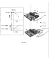
図1に示すように、自動航空機システム操作方法100は:航空機システムを飛行モードで操作するステップS120と、スタンバイ事象を検出するステップS150と、スタンバイモードの航空機システム操作するステップS160と、を具える。この方法100は、さらに、飛行事象を検出するステップS110と、制御指示を受信するステップS130と、及び/又は制御指示に応じて航空機システムを操作するステップS140と、を具える。
1. Overview As shown in FIG. 1, an automated aircraft system operating method 100 includes: step S120 for operating an aircraft system in flight mode; step S150 for detecting a standby event; and step S160 for operating an aircraft system in standby mode. Yeah. The method 100 further includes step S110 for detecting a flight event, step S130 for receiving a control instruction, and / or step S140 for operating the aircraft system in response to the control instruction.
この方法は、航空機システムの飛行を、制御指示の受信に関係なく、自動的に中止するように機能する。第1変形例では、航空機システムは、航空機システムが飛行中に制止されていることを自動的に検出し、航空機システムの制止の検出に応じて自動的にスタンバイモードで操作する。特定例では、航空機システムは、ユーザが航空機システムが飛行中であるあるいは空中にあることを把握すると(例えば、図2に示すように)、そのリフト機構を低速にするか停止させる。第2変形例では、航空機システムが着陸地点を自動的に認識し、その着陸地点に着陸するように自動的に操作を行う。第1の特定例では、航空機システムは、航空機システムの下のユーザの手を自動的に検出し(例えば、視野が下側を向いたカメラと、視覚分析法を用いて)、プロペラの速度を徐々に落として、ユーザの手の上に航空機システムを着陸させる。第2特定例では、航空機システムが航空機システムの前にある着陸地点を自動的に検出し、その着陸地点に向けて自動的に飛行し、リフト機構を自動的に制御して着陸地点に着陸させる。しかしながら、この方法は、他の方法で航空機システムの飛行を中止することができる。 This method functions to automatically cease flight of the aircraft system regardless of receipt of control instructions. In a first variation, the aircraft system automatically detects that the aircraft system is blocked during the flight and automatically operates in standby mode in response to detection of the aircraft system being blocked. In a particular example, the aircraft system slows or stops its lift mechanism when the user knows that the aircraft system is in flight or in the air (eg, as shown in FIG. 2). In the second modification, the aircraft system automatically recognizes the landing point and automatically operates to land at the landing point. In a first specific example, the aircraft system automatically detects the user's hand under the aircraft system (eg, using a camera with a field of view facing downwards and visual analysis) and determines the speed of the propeller. Gradually drop and land the aircraft system on the user's hand. In the second specific example, the aircraft system automatically detects a landing point in front of the aircraft system, automatically flies toward the landing point, and automatically controls the lift mechanism to land at the landing point. . However, this method can abort the flight of the aircraft system in other ways.
この方法は、さらに、制御指示の受信に関係なく、航空機システムを自動的に飛行させるように機能する。第1変形例では、航空機システムが解放されると(例えば、ユーザの手から)、航空機システムが自動的にホバリングする(例えば、適所で)。第2変形例では、航空機システムは、加力ベクトルに沿って投げられているあるいは押されている航空機システムに応じて、加力ベクトルに沿って自動的に飛行し、停止し、ホバリングする。第3変形例では、航空機システムは、ユーザの手から自動的に離陸することができる。しかしながら、この方法は、その他の方法で、航空機システムを飛行させることができる。 The method further functions to automatically fly the aircraft system regardless of receiving control instructions. In a first variation, when the aircraft system is released (eg, from the user's hand), the aircraft system automatically hovers (eg, in place). In a second variant, the aircraft system will automatically fly along the force vector, stop and hover depending on the aircraft system being thrown or pushed along the force vector. In a third variation, the aircraft system can automatically take off from the user's hand. However, this method can fly the aircraft system in other ways.
2.利点
この方法は、従来のシステムを超える数々の利点を提供できる。第1に、航空機システムのスタンバイモードに自動的に入り、航空機システムの始動に応じて自動的に飛行させ、及び/又はユーザの手又はユーザが特定する着陸地点に自動的に着陸することによって、この方法は、航空機システムとのユーザの間のより使いやすい相互作用を可能にする。第2に、外部からの制御指示を受けることに関係なく、自動的に動作することによって、この方法は、ユーザを航空機システムのフライトのこれらの態様を制御しなくても済むようになる。これによって、ユーザは補助システム(例えば、カメラシステム)を制御したり、マルチタスク処理を最小限にしたり、あるいは、航空機システムのフライトに必要なユーザとの相互作用を減らすことができる。しかしながら、この方法は、その他の適切な利点セットを提供することができる。
2. Advantages This method can provide a number of advantages over conventional systems. First, by automatically entering the standby mode of the aircraft system, automatically flying in response to the startup of the aircraft system, and / or automatically landing at the user's hand or landing point specified by the user, This method allows for a more user-friendly interaction between the user and the aircraft system. Second, by operating automatically regardless of receiving external control instructions, this method eliminates the need for the user to control these aspects of the aircraft system flight. This allows the user to control auxiliary systems (eg, camera systems), minimize multitasking, or reduce user interaction required for aircraft system flights. However, this method can provide other suitable sets of benefits.
3.システム
図5に示すように、この方法は、一またはそれ以上の航空機システム1で使用することが好ましく、選択的に、遠隔コンピュータシステム(例を図6に示す)と共に、あるいはその他の適切なシステムと共に使用することができる。航空機システム1は、飛行するよう機能し、さらに、写真を撮影する、貨物を送達する、及び/又は無線通信を中継するように機能する。航空機システム1は、好ましくは、回転翼航空機(例えば、クアッドコプター、ヘリコプター、サイクロコプター、他)であるが、代替的に、固定翼航空機、軽航空機であってもよく、あるいはその他の適切な航空機システム1であってもよい。航空機システム1は、リフト機構、電源、センサ、処理システム、通信システム、本体、及び/又はその他の適切な機器を具えている。
3. System As shown in FIG. 5, the method is preferably used in one or
航空機システムのリフト機構は、リフトを提供するように機能し、好ましくは、一またはそれ以上のモータで駆動する(個別にあるいは全体的に)ロータセットを具えている。各ロータは、好ましくは、対応するロータ軸を中心に回転し、そのロータ軸に垂直な対応するロータ面を規定し、そのロータ面上の受風面積を掃引するように構成されている。モータは、好ましくは、ロータに十分な動力を提供して、航空機システムを飛行できるように構成されており、より好ましくは、2またはそれ以上のモードで操作可能であり、そのうちの少なくとも一つは、飛行に十分な動力を提供するモードを具え、また、そのうちの少なくとも一つは、飛行に必要な動力より少ない動力を提供する(例えば、最小飛行動力の10%を提供する、他)モードを具える。モータによって提供される動力は、好ましくは、ロータがそのロータ軸を中心に回転する角速度に影響する。航空機システムの飛行中は、ロータセットは、航空機システム1によって発生する総空気力学的力(おそらく、高対気速度で飛行中の場合など、本体で発生するけん引力を除く)のほぼすべて(例えば、99%以上、95%以上、90%以上、75%以上)を共働して又は個別に発生するように構成されていることが好ましい。代替的にあるいは追加で、航空機システム1は、ジェットエンジン、ロケットエンジン、翼、太陽帆、及び/又はその他の適切な力発生機器といった、航空機システムの飛行用の力を発生するよう機能する、その他の適切な飛行用機器を具えていてもよい。
The lift mechanism of an aircraft system functions to provide a lift and preferably comprises a rotor set (individually or entirely) driven by one or more motors. Each rotor is preferably configured to rotate about a corresponding rotor axis, define a corresponding rotor surface perpendicular to the rotor axis, and sweep a wind receiving area on the rotor surface. The motor is preferably configured to provide sufficient power to the rotor to fly the aircraft system, more preferably it can be operated in two or more modes, at least one of which is A mode that provides sufficient power for flight, and at least one of them provides a mode that provides less power than required for flight (eg, provides 10% of minimum flight power, etc.) Prepare. The power provided by the motor preferably affects the angular speed at which the rotor rotates about its rotor axis. During flight of the aircraft system, the rotor set is capable of nearly all of the total aerodynamic forces generated by the aircraft system 1 (except perhaps the tractive forces generated by the body, such as when flying at high airspeeds). , 99% or more, 95% or more, 90% or more, or 75% or more) is preferably generated in cooperation or individually. Alternatively or additionally, the
一変形例では、航空機システム1は、4つのロータを具えており、各ロータは航空機システム本体のコーナーに配置されている。4つのロータは、好ましくは航空機システム本体の周りにほぼ均等に分散しており、各ロータ面は好ましくは、航空機システム本体の外側面(例えば、縦軸と横軸を含む)にほぼ平行(例えば、10°以内)である。ロータは、好ましくは、航空機システム1全体の比較的大きな部分(例えば、90%、80%、75%、又は、航空機システムの設置面積の大部分、又は、航空機システム1のその他の適切な割合)を占めている。例えば、各ロータの直径の2乗は、システムの主平面(例えば、外側面)上の航空機システム1の投影の凸包の閾値より大きくてもよい(例えば、10%、50%、75%、90%、110%)。しかしながら、ロータは別の方法で配置できる。
In one variant, the
航空機システムの電源は、航空機システムの動的機器(例えば、リフト機構のモータ、電源、他)に電力を供給する。電源は、本体に装着して、動的機器に接続することができ、あるいは別の方法で配置できる。電源は、再充電可能なバッテリィ、二次電池、一次電池、燃料電池、あるいは、その他の適切な電源である。 Aircraft system power supplies provide power to aircraft system dynamic equipment (eg, lift mechanism motors, power supplies, etc.). The power source can be attached to the body and connected to a dynamic device, or it can be arranged in another way. The power source is a rechargeable battery, secondary battery, primary battery, fuel cell, or other suitable power source.
航空機システムのセンサは、航空機システムの周囲環境及び/又は航空機システム操作を表す信号を取得するよう機能する。センサは、好ましくは本体に装着されているが、代替的にその他の適切な機器に装着することもできる。センサは、好ましくは電源から電力が供給され、プロセッサによって制御されるが、その他の適切な機器に接続して相互作用するようにしてもよい。センサは:カメラ(例えば、CCD、CMOS、多重スペクトル、有視界、ハイパースペクトル、立体、他)、方位センサ(例えば、慣性測定センサ、加速度計、ジャイロスコープ、高度計、磁力計、他)、音響センサ(例えば、トランスデューサ、マイクロホン、他)、バロメータ、光センサ、温度センサ、電流センサ(例えば、ホール効果センサ)、風量計、電圧計、タッチセンサ(例えば、抵抗、容量、他)、近接センサ、力センサ(例えば、歪ゲージ計、ロードセル)、振動センサ、化学センサ、太陽光センサ、位置センサ(例えば、GPS、GNSS、三角測量、他)、又はその他の適切なセンサ、の一またはそれ以上を具えていてもよい。一変形例では、航空機システム1は、航空機システム本体の第1端部に沿って装着した(例えば、静的に、又は回転可能に)、本体の外側面と交差する視野を持つ第1カメラと;航空機システム本体の底部に沿って装着した、外側面にほぼ平行な視野を持つ第2カメラと;高度計と加速度計などの方位センサセットと、を具える。しかしながら、システムは、その他の適切な数のセンサタイプを具えていてもよい。
Aircraft system sensors function to obtain signals representative of the ambient environment of the aircraft system and / or aircraft system operation. The sensor is preferably mounted on the body, but can alternatively be mounted on other suitable equipment. The sensor is preferably powered by a power source and controlled by a processor, but may be connected to and interact with other suitable equipment. Sensors: cameras (eg, CCD, CMOS, multispectral, visual field, hyperspectral, stereoscopic, etc.), orientation sensors (eg, inertial measurement sensors, accelerometers, gyroscopes, altimeters, magnetometers, etc.), acoustic sensors (Eg, transducer, microphone, etc.), barometer, light sensor, temperature sensor, current sensor (eg, Hall effect sensor), air flow meter, voltmeter, touch sensor (eg, resistance, capacitance, etc.), proximity sensor, force Comprising one or more sensors (eg strain gauges, load cells), vibration sensors, chemical sensors, solar sensors, position sensors (eg GPS, GNSS, triangulation, etc.) or other suitable sensors It may be. In one variation, the
航空機システムの処理システムは、航空機システム操作を制御するよう機能する。処理システムは、以下の方法を実行できる;飛行中に航空機システムを安定させる(例えば、飛行中の航空機システムの揺れを最小にするようロータを選択的に操作する);遠隔制御指示を受信し、解析し、それに基づいて航空機システム1を操作する;あるいは、別のやり方で航空機システム操作を制御する。処理システムは、好ましくは、センサでサンプリングした測定値を、より好ましくは、異種センサでサンプリングした測定値の組み合わせ(例えば、カメラと加速度計のデータを組み合わせる)を受信し、解析するように構成されている。航空機システム1は、一またはそれ以上処理システムを具えており、異なるプロセッサが同じ機能を実行することができる(例えば、マルチコアシステムとして機能する)か、あるいは特化されていてもよい。処理システムは:プロセッサ(例えば、CPU、GPU、マイクロプロセッサ、他)、メモリ(例えば、フラッシュ、RAM、他)、あるいはその他の適切な機器、の一またはそれ以上を具えていてもよい。処理システムは、好ましくは本体に装着されているが、代替的にその他の適切な機器にとりつけてもよい。処理システムは、好ましくは電源によって電力供給されているが、その他の方法で電力供給するようにしてもよい。処理システムは、好ましくはセンサ、通信システム、及びリフト機構に接続され、これらを制御するが、追加で、あるいは代替的に、その他の適切な機器に接続して、これと相互作用するようにしてもよい。
The processing system of the aircraft system functions to control aircraft system operation. The processing system can perform the following methods: stabilize the aircraft system during flight (eg, selectively operate the rotor to minimize swinging of the aircraft system during flight); receive remote control instructions; Analyze and operate
航空機システムの通信システムは、一またはそれ以上の遠隔コンピュータシステムと通信するように機能する。通信モジュールは、長距離通信モジュール、短距離通信モジュール、あるいはその他の適切な通信モジュールである。通信モジュールは有線/又は無線通信を容易にする。通信モジュールの例には、802.11x、Wi−Fi、Wi−Max、NFC、RFID、Bluetooth、Bluetooth Low Energy、ZigBee、セルラー通信工業会(例えば、2G、3G、4G、LTE、他)、ラジオ(RF)、有線接続(例えば、USB)、あるいはその他の適切な通信モジュール又はその組み合わせ、がある。通信システムは、好ましくは電源から電力を供給するが、その他の方法で電力供給してもよい。通信システムは、好ましくは、処理システムに接続されているが、追加で、あるいは代替的に、その他の適切な機器に接続して相互作用することができる。 The communication system of the aircraft system functions to communicate with one or more remote computer systems. The communication module is a long distance communication module, a short distance communication module, or other suitable communication module. The communication module facilitates wired / wireless communication. Examples of communication modules include 802.11x, Wi-Fi, Wi-Max, NFC, RFID, Bluetooth, Bluetooth Low Energy, ZigBee, Cellular Telecommunications Industry Association (eg 2G, 3G, 4G, LTE, etc.), radio (RF), wired connection (eg, USB), or other suitable communication module or combination thereof. The communication system is preferably powered from a power source, but may be powered in other ways. The communication system is preferably connected to the processing system, but can additionally or alternatively connect to and interact with other suitable equipment.
航空機システムの本体は、航空機システムの機器を支持するように機能する。本体には、さらに、航空機システムの機器を保護する機能もある。本体は、好ましくは、通信システム、電源、処理システムを実質的に囲んでいるが、別の方法で構成してもよい。本体は、プラットフォーム、ハウジング、あるいはその他の適切な構造を具えている。一変形例では、本体は、通信システムと、電源と、処理システムを保護する主本体と、ロータ回転面に平行に延在し、主本体の第1及び第2側部に沿って配置した第1及び第2のフレーム(例えば、ケージ)を具えていてもよい。これらのフレームは、回転するロータと保持機構(例えば、ユーザの手のような保持機構)との間の中間機器として機能する。フレームは、本体の単一側部に沿って(例えば、ロータの底に沿って、ロータの上部に沿って)、本体の第1及び第2側部に沿って(例えば、ロータの上部及び底に沿って)延在する、ロータを囲む(例えば、ロータの全側部に沿って延在する)、あるいは別の方法で構成されていてもよい。フレームは、主本体に静的に、あるいは動作可能に装着されている。 The body of the aircraft system functions to support the aircraft system equipment. The main body also has a function of protecting aircraft system equipment. The body preferably substantially encloses the communication system, power source, and processing system, but may be configured in other ways. The body includes a platform, a housing, or other suitable structure. In one variation, the main body is a communication system, a power source, a main body that protects the processing system, a first main body that extends parallel to the rotor rotation surface, and is disposed along the first and second sides of the main body. One and a second frame (eg, a cage) may be provided. These frames function as an intermediate device between the rotating rotor and a holding mechanism (for example, a holding mechanism such as a user's hand). The frame may be along a single side of the body (eg, along the bottom of the rotor, along the top of the rotor), along the first and second sides of the body (eg, top and bottom of the rotor). May extend around, surround the rotor (eg, extend along all sides of the rotor), or may be otherwise configured. The frame is statically or operably attached to the main body.
フレームは、一またはそれ以上のロータを周囲環境に流体連通して接続する一またはそれ以上の開口(例えば、空気流開口)を具えていてもよい。この開口は、周囲環境とロータとの間で空気が流れる及び/又はその他の適切な流体が流れるように機能する(例えば、ロータが、航空機システムを周囲環境を通って移動させる空気力学的力を作ることができる)。この開口は、細長であってもよく、相当の長さと幅を有するものであってもよい。開口は、ほぼ同じであるか、互いに異なっていてもよい。開口は、好ましくは、保持機構の構成要素(例えば、手の指)が開口を通過しないように十分に小さい。ロータ近傍のフレームの幾何学的透明性(例えば、総面積に対する開面積の比)は、航空機システムが飛行できる、より好ましくは高性能飛行操縦できるように十分に大きいことが好ましい。例えば、各開口は、閾値サイズ(例えば、全寸法における閾値サイズより小さい、閾値サイズより狭いが、有意に長い細長いスロット、他)より小さくてもよい。特定の例では、フレームは80なし90%の幾何学的透明性を有し、開口(例えば、円、正五角形などの多角形、他)は、各々、直径12乃至16mmの限局性の円を規定する。しかしながら、本体は別の方法で構成することができる。 The frame may include one or more openings (eg, air flow openings) that connect one or more rotors in fluid communication with the surrounding environment. This opening functions to allow air to flow between the ambient environment and the rotor and / or other suitable fluid (e.g., the aerodynamic forces that cause the rotor to move the aircraft system through the ambient environment). Can be made). The opening may be elongated or may have a considerable length and width. The openings may be substantially the same or different from each other. The opening is preferably small enough so that components of the retention mechanism (eg, fingers of the hand) do not pass through the opening. The geometric transparency of the frame in the vicinity of the rotor (eg, the ratio of the open area to the total area) is preferably large enough so that the aircraft system can fly, more preferably high performance flight maneuvers. For example, each opening may be smaller than a threshold size (e.g., an elongate slot that is smaller than the threshold size in all dimensions, narrower than the threshold size but significantly longer, etc.). In a specific example, the frame has 80% and 90% geometric transparency, and the openings (eg, circles, polygons such as regular pentagons, etc.) each form a localized circle with a diameter of 12-16 mm. Stipulate. However, the body can be configured in other ways.
本体(及び/又はその他の適切な航空機システム機器)は、保持機構(例えば、人の手、航空機システムドック、クロー、他)によって保持できる保持領域を規定することができる。この保持領域は、好ましくは、一またはそれ以上のロータの一部を取り囲んでおり、より好ましくは全ロータを完全に取り囲んで、これによって、ロータと保持機構又は航空機システム1近傍のその他の物体の間の意図しない相互作用を防止している。例えば、保持領域の航空機システム面(例えば、外側面、ロータ面、他)への投影は、同じ航空機システム面への一またはそれ以上のロータの掃引領域(例えば、一のロータの掃引領域、ロータセットの全掃引領域、他)の投影と重なっていてもよい(例えば、部分的に、完全に、大部分が、少なくとも90%が、他)。
The body (and / or other suitable aircraft system equipment) can define a holding area that can be held by a holding mechanism (eg, a human hand, aircraft system dock, claw, etc.). This holding area preferably surrounds part of one or more rotors, more preferably completely surrounds all rotors, so that the rotor and the holding mechanism or other object in the vicinity of the
航空機システム1は、さらに、入力(例えば、マイクロホン、カメラ、他)、出力(例えば、ディスプレイ、スピーカ、発光素子、他)、又はその他の適切な機器を具えていてもよい。
The
遠隔コンピュータシステムは、補助ユーザ入力を受信するように機能し、さらに、自動的に航空機システム1用の制御指示を生成して、航空機システム1にこの制御指示を送信する。各航空機システム1は、一またはそれ以上の遠隔コンピュータシステムによって制御することができる。遠隔コンピュータシステムは、好ましくは、クライアント(例えば、ネーティブアプリケーション、ブラウザアプリケーション、他)を介して航空機システム1を制御するが、その他の方法で航空機システム1を制御するようにしてもよい。遠隔コンピュータシステムは、ユーザのデバイス、遠隔サーバシステム、接続器具であってもよく、あるいはその他の適切なシステムであってもよい。ユーザデバイスの例には、タブレット、スマートホン、モバイルホン、ラップトップ、時計、ウエアラブルデバイス(例えば、眼鏡)、又はその他の適切なユーザデバイスである。ユーザデバイスは、電力貯蔵システム(例えば、バッテリィ)、処理システム(例えば、CPU、GPU、メモリ、他)、ユーザ出力(例えば、ディスプレイ、スピーカ、振動機構、他)、ユーザ入力(例えば、キーボード、タッチスクリーン、マイクロホン、他)、位置測定システム(例えば、GPSシステム)、センサ(例えば、光センサとカメラなどの光学センサ、加速度計、ジャイロスコープ、及び高度計などの方位センサ、マイクロホンなどの音響センサ、他)、データ通信システム(例えば、WiFiモジュール、BLE、セルラーモジュール、他)、あるいはその他の適切な機器、がある。
The remote computer system functions to receive auxiliary user input, and further automatically generates control instructions for the
4.方法
飛行事象を検出するステップS110は、差し迫った操作事象の要求、あるいは別の航空機システムの飛行に関連する要求を検出するように機能する。差し迫った操作事象は、自然落下(例えば、重力ベクトルに平行な第1軸に沿った航空機システムの動き)、緊急落下、あらかじめ決められた方位内の航空機システムの配置(例えば、0.5秒といった所定時間の重力ベクトルに直交する方向からあらかじめ決められた範囲内における主航空機面の配置)、空中での航空機システムの手動サポート(例えば、加速度パターン、回転パターン、振動パターン、温度パターン、他に基づく)、あるいはその他の適切な差し迫った操作事象であってもよい。ステップS110は、好ましくは、差し迫った操作に関連するセンサ信号の変化の検出を具える。この変化は、好ましくは、搭載されたセンサ(例えば、方位センサ)から受信した信号に基づいて処理システムによって検出されるが、代替的に、遠隔コンピュータシステム(例えば、センサ信号が遠隔コンピュータシステムに送信される)によって検出するようにしてもよく、あるいはその他の適切なシステムで検出してもよい。あらかじめ決められた変化は、製造者によって設定する、遠隔コンピュータシステムを稼働させているクライアントから受信する、ユーザから受信する、あるいは別の方法で決定することができる。この変化は:あらかじめ決められた頻度で、新たに方位センサ信号を受信するたびに、あるいはその他の適切な時点で、決定することができる。あらかじめ決められた変化は、信号の変化、パラメータの変化(例えば、加速度変化量、速度変化量、他)、変化率(例えば、加速度変化率)、又はその他の適切な変化であってもよい。
4). Method The step S110 of detecting a flight event functions to detect a request for an impending operational event, or a request related to the flight of another aircraft system. Imminent operational events include natural fall (eg, movement of the aircraft system along a first axis parallel to the gravity vector), emergency drop, placement of the aircraft system within a predetermined orientation (eg, 0.5 seconds) Main aircraft plane arrangement within a predetermined range from a direction orthogonal to the gravity vector for a given time), based on manual support of aircraft system in the air (eg acceleration pattern, rotation pattern, vibration pattern, temperature pattern, etc. ), Or any other suitable imminent operational event. Step S110 preferably comprises detecting a change in sensor signal associated with the impending operation. This change is preferably detected by the processing system based on a signal received from an onboard sensor (eg, an orientation sensor), but alternatively, a remote computer system (eg, a sensor signal is transmitted to the remote computer system). Or may be detected by other suitable systems. The predetermined change can be set by the manufacturer, received from a client running a remote computer system, received from a user, or otherwise determined. This change can be determined: at a predetermined frequency, each time a new orientation sensor signal is received, or at any other suitable time. The predetermined change may be a signal change, a parameter change (eg, an acceleration change amount, a speed change amount, etc.), a change rate (eg, an acceleration change rate), or other suitable change.
差し迫った操作を表す変化は、ユーザから受け取っても、クライアントから受け取っても、自動的に学習(例えば、ラベル化した「加速度計パターンの訓練学習に基づいて」)してもよく、あるいはその他の方法で決定できる。実際の変化は、その実際の変化が差し迫った操作を表すあらかじめ決められた変化に実質的に合致するのであれば、差し迫った操作を表す変化であると考えられ、差し迫った操作を表す変化として分類され、差し迫った操作を表すパターンパラメータ値と実質的に合致し、あるいはその他の方法で検出できる。 Changes that represent an impending operation may be received from the user, received from the client, automatically learned (eg, based on training training on a labeled accelerometer pattern), or other Can be determined by the method. An actual change is considered to be a change that represents an impending operation if the actual change substantially matches a predetermined change that represents the impending operation, and is classified as a change that represents an impending operation. And substantially matches the pattern parameter value representing the impending operation, or can be detected by other methods.
方位センサ信号は、あらかじめ決められた変化を周期的にモニタしており、この信号をモニタリングするステップは、以前の方位センサ信号セットを一時的にキャッシングするステップと、キャッシュした方位センサ信号と、新しい方位センサ信号との変化を決定するステップと、を具える。しかしながら、方位センサ信号は他の方法でモニタするようにしてもよい。一実施例(図3に示す)では、あらかじめ決められた変化が加速度(例えば、正しい加速度)、あるいは実質的にゼロに等しくなっている(例えば、0.1gより小さい、0.3gより小さい、航空機システムで観察された典型的な加速度の閾値の一部より例えば、10%又は30%小さい、他)加速度成分(例えば、重力ベクトルに関連する軸に沿った)、ゼロに向けての降下、閾値レートを超えたゼロに向けての降下、あるいは、その他の適切な絶対値変化、変化パターン、又は自然落下を表すその他の変化の表示であってもよい。重力ベクトルに関連する軸は、重力ベクトルの平行な軸、あらかじめ決められた航空機システムの軸及び/又は方位センサ軸(例えば、航空機システムの側方面に直交する中心軸)であってもよく、あるいは、その他の適切な軸であってもよい。特定の例では、飛行事象を検出するステップS110は、航空機システム本体に搭載された加速度計で実質的にゼロに等しい適切な加速度を検出するステップを具える。 The azimuth sensor signal periodically monitors a predetermined change, and monitoring the signal includes temporarily caching a previous azimuth sensor signal set, a cached azimuth sensor signal, and a new Determining a change from the orientation sensor signal. However, the orientation sensor signal may be monitored by other methods. In one embodiment (shown in FIG. 3), the predetermined change is acceleration (eg, correct acceleration) or substantially equal to zero (eg, less than 0.1 g, less than 0.3 g, Acceleration components (eg, along the axis associated with the gravity vector), descent towards zero, eg, 10% or 30% less than some of the typical acceleration thresholds observed in aircraft systems, It may be a drop towards zero above the threshold rate, or other suitable absolute value change, change pattern, or other change indication representing a natural fall. The axis associated with the gravity vector may be a parallel axis of the gravity vector, a predetermined aircraft system axis and / or orientation sensor axis (eg, a central axis orthogonal to the lateral side of the aircraft system), or Other suitable axes may be used. In a particular example, detecting the flight event S110 comprises detecting an appropriate acceleration substantially equal to zero with an accelerometer mounted on the aircraft system body.
この実施例の第1変形例では、この軸が航空機システムの底部(例えば、航空機システムのハウジングの底)に直交する軸である。第2変形例では、航空機システムが重力ベクトルに平行な軸を認識できる。これは、重力加速度の大きさとほぼ同じであるか、それより高い測定した加速度が(例えば、あらかじめ決められた時間)測定された軸を認識するステップを具える。この変形例では、あらかじめ決められた変化が生じたことの決定時に、この方法が、追加で、その他の軸からのセンサの測定値を分析して、航空機システムが本当に自然落下であるかどうか(例えば、その他の軸からの測定値が、重力加速度の大きさより小さい)、あるいは単に回転していただけであるかどうか(例えば、一又はそれ以上のその他の軸からの測定値が、重力加速度の大きさより大きいか、あるいはそれと同じである)を決定する。追加であるいは代替的に、この変形例では、この方法が、加速度測定値を異種の方位情報(例えば、ジャイロスコープや、カメラなどの一またはそれ以上のセンサからの測定値)と関連付けるステップを具えていてもよい。この方法は、選択的に、あらかじめ決められた軸(例えば、航空機システムの縦軸)についての測定値を選択的に無視するあるいは考慮しないようにすることもできる。しかしながら、この軸はその他の方法で決定することができ、あるいは単一の軸を用いなくてもよい(例えば、代わりに、トータルの大きさに依存する)。 In a first variation of this embodiment, this axis is the axis orthogonal to the bottom of the aircraft system (eg, the bottom of the aircraft system housing). In the second variant, the aircraft system can recognize an axis parallel to the gravity vector. This includes the step of recognizing an axis whose measured acceleration is approximately the same as or higher than the magnitude of gravitational acceleration (eg, a predetermined time). In this variation, when determining that a predetermined change has occurred, the method additionally analyzes sensor readings from the other axes to determine whether the aircraft system is truly a natural fall ( For example, measurements from other axes are less than the magnitude of gravitational acceleration, or just rotation (eg, measurements from one or more other axes are Is greater than or equal to). Additionally or alternatively, in this variation, the method includes the step of associating acceleration measurements with disparate orientation information (eg, measurements from one or more sensors such as a gyroscope or a camera). It may be. The method may optionally selectively ignore or not take measurements on a predetermined axis (eg, the longitudinal axis of the aircraft system). However, this axis can be determined in other ways, or a single axis may not be used (for example, depending on the total size instead).
第2実施例(図4に示す)では、高度計信号を周期的にモニタして、あらかじめ決められた変化を求めている。このあらかじめ決められた変化は、あらかじめ決められた高度の低下、あらかじめ決められた高度の変化率、あるいはその他の適切な変化である。 In the second embodiment (shown in FIG. 4), the altimeter signal is periodically monitored to obtain a predetermined change. This predetermined change is a predetermined altitude drop, a predetermined altitude change rate, or any other suitable change.
第3実施例では、加速度計及び/又はジャイロスコープ信号を周期的にモニタして、航空機システムがほぼ水平包囲に支持されていることを表示する(例えば、航空機システムの底に対して垂直な軸が、重力ベクトルから、1°、5°、10°、又は15°といった閾値角度内にある)。一例では、空間センサ信号が、航空機システムが閾値時間(例えば、100ms、350ms、1s、2s、5s、他)より長い時間ほぼ水平に支持されていたことを示すときに、ステップS110で飛行事象が検出されるが、航空機システムはスタンバイ状態にあり、ソナーと光センサがフライト制御用の有効データをサンプリングしている。しかしながら、差し迫った操作を表す変化は、他の方法で検出できる。 In a third embodiment, the accelerometer and / or gyroscope signal is periodically monitored to indicate that the aircraft system is supported in a substantially horizontal enclosure (eg, an axis perpendicular to the bottom of the aircraft system). Is within a threshold angle of 1 °, 5 °, 10 °, or 15 ° from the gravity vector). In one example, when the spatial sensor signal indicates that the aircraft system has been supported approximately horizontally for a time longer than a threshold time (eg, 100 ms, 350 ms, 1 s, 2 s, 5 s, etc.), a flight event is detected in step S110. Although detected, the aircraft system is in standby and sonar and light sensors are sampling valid data for flight control. However, changes representing an impending operation can be detected in other ways.
飛行モードにおける航空機システムを操作するステップS120は、航空機システムを飛行させるように機能する。ステップS120は、好ましくは、飛行モードでリフト機構を操作するステップを具えるが追加で、又は代替的に、飛行モードでその他の適切な航空機システムの機器を操作するステップを具えていてもよい。航空機システムは、好ましくは、処理システムによって自動的に操作されるが、代替的に、遠隔コンピュータシステム又はその他の適切なシステムによって自動的に操作するようにしてもよい。航空機システムは、好ましくは、飛行モードS120で、飛行事象を検出するステップS110に応じて自動的に操作されるが、追加であるいは代替的に、飛行事象の検出S120の後、あらかじめ決められた時間経過後、飛行システムの高度があらかじめ決められた高度変化を超えて変化した後(例えば、高度計で検出される)、あるいはその他の適切な時間に操作するようにしてもよい。航空機システムは、好ましくは、操作パラメータセットにしたがって操作され、ここでは、操作パラメータがあらかじめ決められている、選択される(例えば、変化が検出されたときあるいは変化の検出される前のセンサ測定値の組み合わせに基づいて、センサ測定パターンの分類又は組み合わせに基づいて、他)、あるいは他の方法で決定される。操作パラメータには、リフト機構に提供された電力(例えば、電圧、電流、他)、リフト機構の速度又は出力、タイミング、ターゲットセンサ測定値、あるいはその他の適切な操作パラメータが含まれる。 Step S120 of operating the aircraft system in flight mode functions to fly the aircraft system. Step S120 preferably comprises the step of operating the lift mechanism in flight mode, but may additionally or alternatively include the step of operating other suitable aircraft system equipment in flight mode. The aircraft system is preferably operated automatically by the processing system, but may alternatively be operated automatically by a remote computer system or other suitable system. The aircraft system is preferably operated automatically in flight mode S120 in response to step S110 of detecting a flight event, but additionally or alternatively after a flight event detection S120, a predetermined time. After the elapse, the flight system altitude may change beyond a predetermined altitude change (e.g., detected by an altimeter), or may be operated at another appropriate time. The aircraft system is preferably operated according to a set of operating parameters, where the operating parameters are pre-determined and selected (eg, sensor measurements when a change is detected or before a change is detected). Based on the combination of the other, based on the classification or combination of the sensor measurement patterns, etc.), or otherwise. The operational parameters include power (eg, voltage, current, etc.) provided to the lift mechanism, speed or output of the lift mechanism, timing, target sensor measurements, or other suitable operational parameters.
航空機システムは、前向きのカメラ、下向きのカメラ、方位センサ、レーザシステム(例えば、レンジファインダ、LIDAR)、レーダー、ステレオカメラシステム、飛行時間、あるいはその他の適切な、光学、音響、距離測定、あるいはその他のシステムからの信号を用いて、飛行モードで操作できる。航空機システムは、RRT、SLAM、運動学、オプティカルフロー、機械学習、ルールに基づくアルゴリズム、又はその他の適切な方法を用いて信号処理を行うことができる。特定の例では、経路移動モードは、前向きのカメラで撮った一連の画像をサンプリングするステップと、この一連の画像と、航空機システムに搭載されて稼動している位置決め方法(例えば、SLAM)を用いて3−D空間内の航空機システムの物理的位置を自動的に決めるステップを具える。第2特定例では、経路移動モードは、下向きのカメラで撮影した一連の画像をサンプリングするステップ(例えば、60fpsで、あるいはその他の適切な周波数でサンプリング)と、航空機システムの位置又は運動(例えば、速度、加速度)の検出を支援できる、航空機システムと、サンプリングした画像に基づく地上間の明らかな動きを自動的に検出するステップ(例えば、オプティカルフローを用いて)、及び、検出した明らかな動きに基づいて航空機システムのバランス又は位置を自動的に補正するステップと、を具える。第3特定例では、第1特定例を用いて決定した航空機システムの位置と、第2特定例を用いて決定した航空機システムの運動を、フライト制御アルゴリズムに送り、ホバリング、飛行、あるいはその他の航空機システムの制御を行うことができる。 Aircraft systems can be forward-facing cameras, downward-facing cameras, orientation sensors, laser systems (eg, rangefinder, LIDAR), radar, stereo camera systems, time of flight, or other appropriate optical, acoustic, distance measurement, or other It can be operated in flight mode using signals from the system. The aircraft system can perform signal processing using RRT, SLAM, kinematics, optical flow, machine learning, rule-based algorithms, or other suitable methods. In a specific example, the path movement mode uses a step of sampling a series of images taken with a forward-facing camera, the series of images, and a positioning method (e.g., SLAM) installed and operating on an aircraft system. Automatically determining the physical position of the aircraft system in 3-D space. In a second particular example, the path movement mode includes sampling a series of images taken with a downward-facing camera (eg, sampling at 60 fps or other suitable frequency), and the position or motion of the aircraft system (eg, Automatically detect obvious movements between the aircraft system and the ground based on the sampled images (eg, using optical flow) that can help detect the velocity, acceleration), and the detected obvious movements Automatically correcting the balance or position of the aircraft system based on. In the third specific example, the position of the aircraft system determined using the first specific example and the movement of the aircraft system determined using the second specific example are sent to the flight control algorithm to be hovered, flying, or other aircraft The system can be controlled.
飛行モードは、好ましくは、航空機システムの空中位置(例えば、垂直位置、水平位置、他)がほぼ維持されるホバリングモードを具えるが、代替的に書他の適切な飛行モードであってもよい。飛行モードは、好ましくは、航空機システムの方位を、航空機システムの外側面に垂直な中央軸が重力ベクトルにほぼ平行(例えば、20°以内、10°以内、3°以内、1°以内、他)になるように維持するステップを具える。しかしながら、この中央軸は、その他の方法で維持するようにしてもよい。飛行モードは、好ましくは、重力によって航空機システムにかかる力と同じ又は反対に、リフトシステムで力を発生するステップ(例えば、ホバリングに)を具えるが、代替的に、重力より大きい又は小さい縦方向の力を発生する(例えば、高度を上げる又は下げる、及び/又は、航空機システムの縦方向の動きを阻んで、航空機システムをホバリング状態にする)ステップを具えていてもよい。飛行モードは、追加であるいは代替的に、非垂直の力及び/又はトルク(例えば、航空機システムをピッチ又はロールに代える、横方向に動かす又は横方向の動きを阻む、他)を発生するステップを具えていてもよい。例えば、飛行モードは、方位、位置、及び/又は速度変化を検出するステップ、この変化が風によるものか、及び/又は、衝突などの別の外部摂動によるものかを決定するステップ(例えば、風、又は衝突事象として変化を分類し、風の摂動の可能性を決定し、つかみ事象である摂動の可能性を決定するステップ、他)、及び、リフト機構を相殺してこの変化を補正し、元のあるいは所望の位置、方位、及び/又は速度に戻すステップ、を具えていてもよい。 The flight mode preferably comprises a hover mode in which the aircraft system's aerial position (eg, vertical position, horizontal position, etc.) is substantially maintained, but may alternatively be other suitable flight modes. . The flight mode preferably refers to the orientation of the aircraft system and the central axis perpendicular to the outer surface of the aircraft system is approximately parallel to the gravity vector (eg, within 20 °, within 10 °, within 3 °, within 1 °, etc.) Steps to keep to be. However, this central axis may be maintained in other ways. The flight mode preferably comprises a step of generating a force in the lift system (eg, in hovering) that is the same as or opposite to the force applied to the aircraft system by gravity, but alternatively in the longitudinal direction greater or less than gravity. Generating (e.g., raising or lowering altitude and / or preventing longitudinal movement of the aircraft system to place the aircraft system in a hovering state). The flight mode may additionally or alternatively generate non-vertical forces and / or torques (eg, replace the aircraft system with pitch or roll, move laterally or prevent lateral movement, etc.) You may have. For example, the flight mode may include detecting azimuth, position, and / or velocity changes, determining whether the change is due to wind and / or another external perturbation such as a collision (eg, wind Or classify the change as a collision event, determine the possibility of a wind perturbation, determine the possibility of a perturbation that is a grab event, etc.), and offset the lift mechanism to correct this change, Returning to the original or desired position, orientation, and / or speed may be included.
飛行モードは、追加であるいは代替的に、経路移動モード(例えば、直線方向に飛行する、あらかじめ決められた経路に沿って飛行する、他)、プログラムモード(例えば、飛行プログラムに基づいて動的に決定された経路に沿って飛行する、ある者を追跡するあるいは周りをまわる、あるいは、カメラの視野内にその者の顔を維持する、他、といった顔及び/又は身体追跡に基づいて飛行する)、及び/又はその他の適切なモードを具えていてもよい。飛行モードは、追加で、本体に装着した(あるいは、その他の方法で機械的に連結した)航空機カメラを用いて画像を捕捉するステップ(例えば、単一画像を保存するステップ、ビデオをストリーミングするステップ)を具えていてもよい。 The flight mode may additionally or alternatively be a path movement mode (eg, fly in a straight direction, fly along a predetermined route, etc.), a program mode (eg, dynamically based on a flight program) Flying along a determined path, tracking or turning around a person, or keeping a person's face within the camera's field of view, etc., flying based on face and / or body tracking) And / or other suitable modes. The flight mode may additionally include capturing an image using an aircraft camera attached to the body (or otherwise mechanically coupled) (eg, storing a single image, streaming video) ).
飛行モードは追加で又は代替的に、撮像モードを具えていてもよく、ここでは、航空機システムが自動的に撮像ターゲット(例えば、人物、顔、物体、他)を認識し、物理的スペースを通ってこの撮像ターゲットを自動的に追跡するようにその飛行を制御する。一変形例では、航空機システムは、物体認識及び/又は追跡方法、顔認識及び/又は追跡方法、身体認識及び/又は追跡方法、及び/又はその他の適切な方法をサンプリングした画像(例えば、前向きのカメラからの画像)上で稼働させて、撮像ターゲットを認識し追跡する。特定例では、航空機システムは、システム自体の周りのほぼ360°の領域を自動的に撮像する(たとえば、中央軸の周りを回転させて、その周りをカメラを移動させて、360°のカメラを用いて、他)ことができ、自動的に画像から撮像ターゲットを認識して、物理的空間の周りで自動的に撮像ターゲット(例えば、自動的に認識した、あるいは手動で選択した)を追跡することができる。しかしながら、撮像モードは、その他の方法で実行することができる。しかしながら、飛行モードは、その他の適切な操作モードセットを具えていてもよい。 The flight mode may additionally or alternatively comprise an imaging mode, in which the aircraft system automatically recognizes the imaging target (eg person, face, object, etc.) and passes through physical space. The flight is controlled to automatically track the imaging target. In one variation, the aircraft system may sample images (e.g., forward-facing) of object recognition and / or tracking methods, face recognition and / or tracking methods, body recognition and / or tracking methods, and / or other suitable methods. (Image from the camera) to recognize and track the imaging target. In a particular example, the aircraft system automatically images an approximately 360 ° region around the system itself (eg, rotating around a central axis and moving the camera around it to make a 360 ° camera Can be used to automatically recognize imaging targets from images and automatically track imaging targets (eg, automatically recognized or manually selected) around physical space be able to. However, the imaging mode can be executed in other ways. However, the flight mode may comprise other suitable operating mode sets.
航空機システムは、各ロータの角速度及び/又は各ロータに送達される動力を独立して制御することで、飛行モードで操作することができる。しかしながら、ロータはグループであるいはその他の適切な態様で制御することができる。ステップS120は、好ましくは、ロータセットにおいて、航空機システムで発生した総空気力学的力とほぼ等しい、より好ましくは、航空機システムにかかった正味の力とほぼ等しい空気力学的力を発生するステップを具える(例えば、航空機システムは、周囲環境において、有意な空気力学的力を発生する、あるいは、有意な力をかけるように構成されたその他の機器を具えていない)。 The aircraft system can be operated in a flight mode by independently controlling the angular velocity of each rotor and / or the power delivered to each rotor. However, the rotors can be controlled in groups or in any other suitable manner. Step S120 preferably includes generating an aerodynamic force in the rotor set that is approximately equal to the total aerodynamic force generated in the aircraft system, more preferably approximately equal to the net force applied to the aircraft system. (E.g., aircraft systems generate significant aerodynamic forces in the surrounding environment or do not have other equipment configured to apply significant forces).
一変形例では、飛行モードにある航空機システムは、各ロータのロータ角速度を取り込んで、スタンバイロータ速度(例えば、この速度で、ロータセットが飛行空気力学的力より低いスタンバイ空気力学的力を発生する)からフライトロータ速度(例えば、この速度でロータセットがほぼゼロの力、あるいは飛行空気力のわずかな部分といった飛行空気力学的力を発生する)にするステップを具える。この変形例では、飛行ロータ速度は、好ましくは、航空機システムがホバリングするホバリングロータ速度であり;代替的にこの速度はその他の適切な回転速度であってもよい。飛行速度は、あらかじめ設定する(例えば、製造者によって)、クライアントから受信する、自動的に決定する(例えば、信号変化率に基づいて)、あるいはその他の方法で決定することができる。スタンバイロータ速度は、低速であり(例えば、ホバリング速度の割合)、角速度はほぼゼロであり(例えば、ロータは回転していない)、あるいはその他の適切な速度であってもよい。スタンバイロータ速度は、あらかじめ設定する(例えば、製造者によって)、クライアントから受信する、あるいはその他の方法で決定することができる。ロータ速度は、スタンバイロータ速度から飛行ロータ速度に直ちに移行する、方位センサの信号変化率に基づいて移行する、あらかじめ決められた率で移行する、あるいはその他の適切な態様で移行することができる。 In one variation, an aircraft system in flight mode takes the rotor angular speed of each rotor and generates a standby rotor speed (eg, at this speed, the rotor set generates a standby aerodynamic force that is lower than the flying aerodynamic force). ) To the flight rotor speed (e.g., at this speed, the rotor set generates a flight aerodynamic force, such as a nearly zero force, or a fraction of the flight aerodynamic force). In this variation, the flight rotor speed is preferably the hovering rotor speed that the aircraft system will hover; alternatively, this speed may be any other suitable rotational speed. The flight speed can be preset (eg, by the manufacturer), received from the client, automatically determined (eg, based on the rate of signal change), or otherwise determined. The standby rotor speed may be low (eg, a percentage of hovering speed), the angular speed may be approximately zero (eg, the rotor is not rotating), or any other suitable speed. The standby rotor speed can be preset (eg, by the manufacturer), received from the client, or otherwise determined. The rotor speed can transition from standby rotor speed to flight rotor speed immediately, transition based on the signal change rate of the orientation sensor, transition at a predetermined rate, or transition in any other suitable manner.
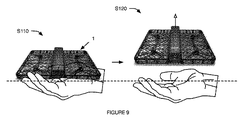
第1例では、回転速度はホバリング速度より高い速度にまず上がって、次いで、ホバリング速度に下がり、航空機システムが自然落下を止めて、自然落下が検出されたのちホバリングするようにしている。これは、支持面が突然外れたとき(図10参照)に航空機システムの自然落下を防止するよう機能する。第2例では、回転速度が加速度の変化率に比例する。特定例では、加速度の変化が自然落下に関連する変化率を超えるときに、回転速度がホバリング速度より早い(例えば、航空機システムが投げおろされたとき)。これは、航空機システムがより早くリカバーするように、あるいは初期の高度(例えば、変化が検出される前又はその後に測定した)をリカバーするように機能する。第2特定例では、回転速度が加速度の変化量に比例して上がる。操作中は、これによって、航空機システムがユーザから徐々に解放されるにつれて(図7参照)ロータが徐々にスプールアップする。第3特定例では、ロータの速度はあらかじめ決められた率で早くなる。操作中は、これによって、ロータが徐々にスプールアップして、航空機システムをユーザの手といった支持面から徐々に持ち上げる(図9参照)。この特定例では、この方法は追加で、支持面が突然取り外されたときに第1例に切り替えるステップを具える(例えば、方位センサ信号の突然の変化から決定する)。回転速度は、選択的に制限されて、伴流効果を防止するあるいは最小限にすることができる。しかしながら、リフト機構はその他の方法で、変化の検出に応じて操作することができる。 In the first example, the rotation speed first increases to a speed higher than the hovering speed, then decreases to the hovering speed, and the aircraft system stops the natural fall so that the hover is performed after the natural fall is detected. This functions to prevent natural fall of the aircraft system when the support surface is suddenly removed (see FIG. 10). In the second example, the rotation speed is proportional to the rate of change of acceleration. In a specific example, when the change in acceleration exceeds the rate of change associated with natural fall, the rotational speed is faster than the hovering speed (eg, when the aircraft system is thrown down). This functions to allow the aircraft system to recover faster or to recover the initial altitude (eg, measured before or after a change is detected). In the second specific example, the rotation speed increases in proportion to the amount of change in acceleration. During operation, this causes the rotor to gradually spool up as the aircraft system is gradually released from the user (see FIG. 7). In the third specific example, the speed of the rotor increases at a predetermined rate. During operation, this causes the rotor to gradually spool up and gradually lift the aircraft system from a support surface such as the user's hand (see FIG. 9). In this particular example, the method additionally comprises switching to the first example when the support surface is suddenly removed (e.g., determined from a sudden change in orientation sensor signal). The rotational speed can be selectively limited to prevent or minimize wake effects. However, the lift mechanism can be operated in other ways in response to detecting changes.
この方法は、選択的に、第2軸に関連するセンサ信号をモニタするステップと、第2軸に関連するセンサ信号に基づいてリフト機構の操作パラメータ(差し迫った操作の検出に応じたリフト機構の操作用)を決定するステップを具える。これは、停止又はホバリングの前に、航空機システムを第2軸に沿った距離だけ横に移動させるリフト機構操作パラメータを選択するよう機能する。第2軸は、好ましくは重力ベクトルにほぼ平行な軸と異なる(例えば、重力ベクトルにほぼ平行な軸に直交する、この軸に対して非ゼロ角度、他)が、代替的に同じでもよい。これらの軸は、航空機システムに対して固定されていてもよく、あるいは動的に変形されてもよい(例えば、可能であれば加速度計、ジャイロスコープ、カメラ、及び/又はその他の適切なセンサでサンプリングした測定値に基づいて、これらの軸を重力及び/又は周囲環境に対して、固定するよう試みる)。リフト機構操作パラメータの決定に考慮される第2軸用のセンサ信号は、第1軸用のセンサ信号と同時に、差し迫った操作の変化が検出される前、差し迫った操作の変化が検出された後(例えば、変化の検出に応じて)、あるいはその他の適時に取得したセンサ信号であってもよい。この距離は、あらかじめ決められていても、時間に基づいて決めても(例えば、航空機システムが解放された1秒間に第2軸に沿って横切る)、かかった力の量に基づいて決めてもよく、あるいはその他の適切な方法で決めてもよい。 The method optionally includes monitoring a sensor signal associated with the second axis, and operating parameters of the lift mechanism based on the sensor signal associated with the second axis (the lift mechanism in response to detection of an impending operation). A step of determining (for operation). This functions to select lift mechanism operating parameters that move the aircraft system laterally a distance along the second axis prior to stopping or hovering. The second axis is preferably different from an axis that is generally parallel to the gravity vector (eg, orthogonal to an axis that is approximately parallel to the gravity vector, a non-zero angle relative to this axis, etc.), but may alternatively be the same. These axes may be fixed with respect to the aircraft system or may be dynamically deformed (eg, with an accelerometer, gyroscope, camera, and / or other suitable sensor if possible). Based on sampled measurements, attempt to fix these axes to gravity and / or the surrounding environment). The sensor signal for the second axis, which is taken into consideration for determining the lift mechanism operation parameter, is the same as the sensor signal for the first axis, before the change of the impending operation is detected, and after the change of the imminent operation is detected. It may be a sensor signal (for example, in response to detection of a change) or other timely acquired sensor signal. This distance can be predetermined, based on time (eg, traversing along the second axis in the second second that the aircraft system is released), or based on the amount of force applied. Or may be determined by other suitable methods.
図8に示す一変形例では、第2軸が本体の縦軸に対して平行であってもよい(例えば、カメラの視野と交差する)。第2軸に沿った加力を検出するステップ(例えば、変化検出の時間窓内)に応じて、航空機システムは自動的にリフト機構の操作支持を、加力に対向するように決定することができる。これは、航空機システムが、更なる横移動を停止する前に、第2軸に沿ってあらかじめ決められた距離移動できるように機能する。加力及び/又は加わった力の大きさは、第2軸(例えば、第2軸に関する加速度計)をモニタしている方位センサから決める、第2軸に直交する航空機システムの表面に沿って配置した力センサから決める、あるいは、その他の方法で決めることができる。対抗される加力は、あらかじめ決められた条件に合致した時の第2軸の瞬間的な力、差し迫った操作事象検出の時間窓内で測定された加力(例えば、最大力、最小力、他)、差し迫った操作事象検出と同時に測定した加力、あるいは、その他の適切な時間に測定したその他の力であってもよい。一例では、リフト操作指示は、ロータを取り込んで差し迫った操作事象検出の直後に、航空機システムをホバリングさせるステップと、航空機システムが差し迫った操作事象検出後直ちに航空機システムをホバリングさせるようにロータを取り込むステップと、あらかじめ決められた時間加力を用いて惰性で進むようにするステップと、リフト機構を制御して、あらかじめ決めた条件に合致した後に第2軸(又はその他の軸)に沿った更なる横移動をやめリフト機構を制御して航空機システムをホバリングさせる(例えば、ホバリング速度で操作するようリフト機構を制御するステップ)ステップと、を具える。第2例では、リフト操作指示が、加力による第2軸に沿った結果航空機システムの速度又は加速度を決定するステップ、差し迫った操作事象検出直後の第2軸に沿った航空機システムの速度又は加速度を、あらかじめ決められた条件に合致するまで維持するようにロータを取り込むステップと、あらかじめ決められた条件を満足した時に第2軸(又はその他の軸)に沿った更なる横移動を止めるようにリフト機構を制御するステップと、航空機システムをホバリングさせるようにリフト機構を制御するステップ(例えば、リフト機構をホバリング速度で操作するよう制御する)と、を具える。あらかじめ決めた条件は、差し迫った操作事象検出後の閾値時間内に、差し迫った操作事象検出後あらかじめ決めた条件に合致した後に(例えば、あらかじめ決められた距離だけ横移動した後、あらかじめ決められた時間が経過した後、その他)、あるいはその他適切な時間における、差し迫った操作事象検出であってもよい(例えば、ここでは差し迫った操作事象検出直後に、指示が実行される)。一例では、あらかじめ決められた条件は、かかった力の大きさ(例えば加速度の大きさ)に基づいて選択される。加力の大きさは、第2軸に沿ってかけられた力の大きさ、システムにかけられた力のトータルの大きさ(例えば、重力によってかかった力より小さい)であってもよく、あるいは、その他の方法で決めることができる。 In one variation shown in FIG. 8, the second axis may be parallel to the longitudinal axis of the body (eg, intersecting the camera field of view). In response to detecting the force along the second axis (eg, within a change detection time window), the aircraft system may automatically determine operational support for the lift mechanism to oppose the force. it can. This functions to allow the aircraft system to move a predetermined distance along the second axis before stopping further lateral movement. The applied force and / or magnitude of the applied force is determined along the surface of the aircraft system orthogonal to the second axis, as determined from the orientation sensor monitoring the second axis (eg, an accelerometer with respect to the second axis). It can be determined from the force sensor, or can be determined by other methods. The force to be countered is the instantaneous force on the second axis when a predetermined condition is met, the force measured within the time window for detecting an imminent operating event (eg, maximum force, minimum force, Other), a force measured simultaneously with the detection of an imminent operating event, or other force measured at another appropriate time. In one example, the lift maneuver instruction includes the steps of: hovering the aircraft system immediately after detecting an imminent operating event by taking the rotor and taking the rotor to hover the aircraft system immediately after detecting the imminent operating event. And a step to advance by inertia using a predetermined time force, and a further control along the second axis (or other axis) after meeting the predetermined condition by controlling the lift mechanism Stopping lateral movement and controlling the lift mechanism to hover the aircraft system (eg, controlling the lift mechanism to operate at a hover speed). In the second example, the lift operation instruction determines the resulting speed or acceleration of the aircraft system along the second axis due to the applied force, the speed or acceleration of the aircraft system along the second axis immediately after detection of an impending operating event The step of incorporating the rotor to maintain a predetermined condition until a predetermined condition is met, and stopping further lateral movement along the second axis (or other axis) when the predetermined condition is satisfied Controlling the lift mechanism and controlling the lift mechanism to hover the aircraft system (eg, controlling the lift mechanism to operate at a hover speed). The predetermined condition is determined in advance within the threshold time after the detection of the imminent operation event, after the imminent operation event is detected and after the predetermined condition is satisfied (for example, after lateral movement by a predetermined distance, It may be the detection of an impending operating event at another time after the time has passed (or other appropriate time) (eg, the instruction is executed immediately after detecting the imminent operating event). In one example, the predetermined condition is selected based on the magnitude of the applied force (for example, the magnitude of acceleration). The magnitude of the applied force may be the magnitude of the force applied along the second axis, the total magnitude of the force applied to the system (eg, less than the force applied by gravity), or It can be determined by other methods.
第1特定例では、この指示の実行遅延が加力の量に比例しており、航空機システムの解放時のより大きい力がかかるときに、第2軸に沿った航空機システムの更なる横移動を停止する前に、航空機システムがさらに飛行する。第2特定例では、指示の実行遅延が加力の量に反比例しており、航空機システムの開放時により大きい力がかかるとき、停止前により短い距離航空機システムが飛行する。しかしながら、航空機システムは、第2軸に関するセンサ信号に基づいてほかの方法で操作するようにしてもよい。 In the first specific example, the delay in execution of this instruction is proportional to the amount of force applied, and further lateral movement of the aircraft system along the second axis is applied when a greater force is applied when the aircraft system is released. The aircraft system will fly further before it stops. In the second specific example, the instruction execution delay is inversely proportional to the amount of force applied, and a shorter distance aircraft system will fly before stopping when a greater force is applied when the aircraft system is opened. However, the aircraft system may be operated in other ways based on the sensor signal for the second axis.
この方法は、選択的に、航空機システムの高度に関連するセンサ信号をモニタするステップと、高度に基づいてリフト機構操作パラメータを決定するステップを具える。一変形例では、これは、リフト機構操作パラメータを選択して、初期航空機システム高度を取り戻すように機能する(例えば、回復前の自然落下による高度ロスを補償する)。高度は、高度計でサンプリングした信号に基づいて決める、及び/又は、相対高度は画像分析、距離測定(例えば、縦方向距離計を用いて、地面、床、及び/又は、天井からの距離を測定する)ことができる。リフト機構操作パラメータの決定に考慮される高度計信号(及び/又はその他の高度データ)は、第1軸に関するセンサ信号と同時に、差し迫った操作の変化が検出される前、差し迫った操作の変化が検出された後(例えば、変化の検出に応じて)、あるいはその他の適切な時間に取得した高度計信号であってもよい。例えば、この方法は、差し迫った操作事象検出からのあらかじめ決められた時間窓内(例えば、差し迫った操作事象検出の前、差し迫った操作事象検出の前に記録された高度計測定値に基づいた)の初期航空機システム高度を決定するステップと、ロータを巻き上げて差し迫った操作事象検出の直後に航空機システムをホバリングさせるステップと、ロータ速度を、航空機システムが安定した後に航空機システムが初期の航空機システム高度に到達するまで、ロータの速度を上げるステップと、を具える。しかしながら、高度計信号(及び/又はその他の高度データ)は、その他の適切な態様で使用することができる。 The method optionally includes monitoring sensor signals related to aircraft system altitude and determining lift mechanism operating parameters based on the altitude. In one variation, this functions to select lift mechanism operating parameters to regain initial aircraft system altitude (eg, to compensate for altitude loss due to natural fall prior to recovery). The altitude is determined based on the signal sampled by the altimeter, and / or the relative altitude is image analysis, distance measurement (eg, distance from the ground, floor, and / or ceiling using a longitudinal distance meter) can do. The altimeter signal (and / or other altitude data) taken into account for determining the lift mechanism operating parameters is detected simultaneously with the sensor signal for the first axis, before the impending operation change is detected. It may be an altimeter signal acquired after (for example, in response to detecting a change) or at some other suitable time. For example, this method can be used within a predetermined time window from imminent operational event detection (eg, based on altimeter measurements recorded prior to imminent operational event detection, prior to imminent operational event detection). Determining the initial aircraft system altitude, hoisting the rotor system immediately after detecting an impending operational event by rolling up the rotor, and the rotor system reaching the initial aircraft system altitude after the aircraft system has stabilized And increasing the speed of the rotor. However, the altimeter signal (and / or other altitude data) can be used in other suitable ways.
制御指示を受信するステップS130は、ユーザが自動航空機システム操作を増やす及び/又はオーバーライドできるように機能する。制御指示は、好ましくは航空機の飛行中に受信するが、追加で又は代替的に、飛行前及び/又はその他の適切な時間に受信することもできる。処理システムは、好ましくは、制御指示を受信するが、その他の適切なシステムが制御指示を受信することもできる。制御指示は、このましくはユーザから、ユーザ装置から、遠隔コントローラから、及び/又は航空機システムに関連するクライアント(例えば、ユーザシステムを稼働させている)から受信するが、代替的に、航空機システムに関連する位置から(例えば、その位置にあるデバイスから)、航空機システムに搭載したセンサ(例えば、手又は身体信号を解析する)、及び/又はその他の適切なシステムから受信することができる。ユーザは、航空機システムによって認識(例えば、顔あるいは身体の認識といった光学認識を介して)、することができ(例えば、航空機システムのセンサの範囲内で)、認識することができ、さもなければ航空機システムに関連する、又はその他の適切なユーザであってもよい。ユーザデバイス及び/又はクライアントは、航空機システムと対になることができ(例えば、ブルーツース接続を介して、航空機システムの開始時に動的に対になる、製造設備で対になる、他)、航空機システムについての相補的セキュリティキー対を持つ、航空機システムと同じユーザのアカウントに関連する、あるいはその他の方法でこの航空機システムに関連させることができる。制御指示は、ユーザが作成しても、ユーザデバイス又はクライアントで作成しても(例えば、ユーザの入力受信に応じて)、航空機システムに関連する位置にあるデバイスで作成しても、制御指示送信機の特性に基づいて決めても(例えば、位置出現特性、周辺環境音響特性、他)、航空機システムで作成しても、あるいはその他の適切な態様で作成又は決定してもよい。 The step S130 of receiving control instructions functions to allow the user to increase and / or override automatic aircraft system operation. Control instructions are preferably received during flight of the aircraft, but may additionally or alternatively be received before flight and / or at other suitable times. The processing system preferably receives the control instructions, but other suitable systems may receive the control instructions. Control instructions are preferably received from a user, from a user device, from a remote controller, and / or from a client (eg, running a user system) associated with an aircraft system, but alternatively, an aircraft system From a location associated with (e.g., from a device at that location), a sensor mounted on an aircraft system (e.g., analyzing hand or body signals), and / or other suitable systems. The user can be recognized by the aircraft system (eg, via optical recognition such as face or body recognition), can be recognized (eg, within the sensors of the aircraft system), or the aircraft It may be a system related or other suitable user. User devices and / or clients can be paired with an aircraft system (eg, paired dynamically at the start of the aircraft system, paired at a manufacturing facility, etc. via a Bluetooth connection) Can be associated with the same user account as the aircraft system, or otherwise associated with the aircraft system. Control instructions can be created by the user, created by the user device or client (eg, in response to receiving user input), or created by a device at a location associated with the aircraft system. It may be determined based on the characteristics of the aircraft (e.g., position appearance characteristics, ambient environmental acoustic characteristics, etc.), may be created on an aircraft system, or may be created or determined in any other suitable manner.
一変形例では、制御指示が、着陸指示を具えている。第1実施例では、ステップS130が着陸地点を決定する(例えば、自動的に着陸地点を認識する)ステップを具える。これは、処理システム、遠隔コンピュータシステム、あるいはその他の適切なシステムによって、完全に、あるいは部分的に実行することができる。着陸地点は、航空機システムのセンサ測定値に基づいて自動的に決める、制御指示送信機から受信する、ユーザが特定する(例えば、クライアントに)、あるいはその他の方法で決めることができる。 In a variant, the control instruction comprises a landing instruction. In the first embodiment, step S130 includes a step of determining a landing point (for example, automatically recognizing the landing point). This can be done completely or partially by a processing system, a remote computer system, or other suitable system. Landing points can be automatically determined based on aircraft system sensor measurements, received from a control instruction transmitter, specified by a user (eg, to a client), or otherwise determined.
この実施例の第1変形例では、保持機構の位置、タイプ、及び/又は構造に基づいて、保持機構(例えば、人の手、ドッキングステーション、捕獲デバイス、他)が着陸地点であると決められる。この変形例は、好ましくは、保持機構の位置、タイプ、及び/又は構造を光学的に検出するステップ(例えば、画像認識技術、分類技術、回帰技術、ルールに基づいた技術、パターンマッチング技術、他を用いて)を具えるが、追加であるいは代替的に、その他の適切な態様で、この位置、タイプ、及び/又は構造を決定するステップを具えていてもよい。 In a first variation of this embodiment, based on the location, type, and / or structure of the retention mechanism, the retention mechanism (eg, human hand, docking station, capture device, etc.) is determined to be the landing point. . This variant preferably comprises the step of optically detecting the position, type and / or structure of the holding mechanism (eg image recognition technology, classification technology, regression technology, rule-based technology, pattern matching technology, etc. But may additionally or alternatively include determining the position, type, and / or structure in other suitable manners.
例えば、保持機構は、保持機構が人の手であってもよい。第1特定例では、着陸地点が下向きのカメラからの画像を用いて検出した開いた手である(図12参照)。第2特定例では、着陸地点が「つかむことができる」構造(例えば、図13に示すような)にある手である。第3特定例では、着陸地点が手招きゼスチュアをしている手である。 For example, the holding mechanism may be a human hand. In the first specific example, the landing point is an open hand detected using an image from a downward camera (see FIG. 12). In the second specific example, the landing point is a hand in a “grabbable” structure (eg, as shown in FIG. 13). In the third specific example, the landing point is a hand making a beckoning gesture.
この変形例は、あらかじめ決められた構造タイプ(例えば、開いた手、「つかむことができる」手、他)の保持機構用の航空機システムのカメラ(例えば、航空機システムの上部、側部、及び/又は底に配置されている)で捕捉した画像などのセンサデータを周期的に分析する(例えば、視覚分析技術、画像分析技術、他を用いて)ステップと、あらかじめ決められた構造タイプを表すパラメータの検出に応じて着陸地点として保持機構を認識するステップとを具える。 This variation may include an aircraft system camera (e.g., the top, side, and / or of the aircraft system) for a holding mechanism of a predetermined structure type (e.g., open hand, "grasping" hand, etc.). Or periodically (for example using visual analysis techniques, image analysis techniques, etc.) sensor data such as images captured at the bottom, and parameters representing a predetermined structure type And a step of recognizing the holding mechanism as a landing point in response to the detection of.
第1例では、この方法は、赤外線画像セットをサンプリングするステップと、閾値を超える赤外線の特徴を有する画像内の領域を認識するステップと、認識した領域が手であることを決定する(例えば、パターンマッチング、決定論的方法、分類、回帰、確率論、他を用いて)ステップとを具える。例えば、その領域の周囲が、手の基準パターンにほぼ一致する場合、認識した領域が手であるとすることができる。第2例では、この方法は、視界画像セットをサンプリングするステップと、画像の前景から背景をセグメント化するステップと、前景領域が手であることを決定するステップと(例えば、上述した方法を用いて)、を具える。しかしながら、人の手はその他の方法で認識することができる。 In a first example, the method determines the step of sampling an infrared image set, recognizing a region in the image having an infrared feature that exceeds a threshold, and the recognized region being a hand (e.g., Pattern matching, deterministic methods, classification, regression, probability theory, etc.). For example, when the periphery of the region substantially matches the reference pattern of the hand, the recognized region can be assumed to be a hand. In the second example, the method includes sampling a view image set, segmenting the background from the foreground of the image, determining that the foreground region is a hand (eg, using the method described above). And). However, human hands can be recognized in other ways.
この変形例は、選択的に、画像(例えば、下向きのカメラによって記録された)からユーザの手を認識するステップと、その手が航空機システムに関連している特定のユーザの手であるとの認識に応じてその手を着陸地点として認識する(例えば、分類技術、回帰技術、指紋などの生体認証データ、他を用いて)ステップとを具える。例えば、抽出した生体認証データは、航空機システムに、ユーザのデバイスに、あるいは遠隔データベースに保存することができるバイオメトリクスと比較することができる。ここで、ユーザは、その生体認証データが閾値パーセンテージを超えて合致しない場合、拒絶されることがあり、生体認証データが閾値パーセンテージを超えて合致している場合は受領される。この実施例は、選択的に、検出した手が、航空機システムに関連するユーザに関連しない場合、手から受け取った指令を無視する(例えば、その手を非着陸地点と認識する)ステップを具えていてもよい。 This variant optionally includes recognizing a user's hand from an image (eg, recorded by a down-facing camera) and that the hand is a particular user's hand associated with the aircraft system. Recognizing the hand as a landing point in accordance with the recognition (for example, using classification technology, regression technology, biometric data such as fingerprint, etc.). For example, the extracted biometric data can be compared to biometrics that can be stored on the aircraft system, on the user's device, or in a remote database. Here, the user may be rejected if the biometric data does not match over a threshold percentage and is received if the biometric data matches over a threshold percentage. This embodiment optionally includes ignoring a command received from the hand (eg, recognizing the hand as a non-landing point) if the detected hand is not associated with a user associated with the aircraft system. May be.
第2変形例では、着陸地点が、航空機システムの近位側にあるほぼ平坦な面(例えば、重力ベクトルに垂直)である(例えば、上向きのカメラ又は下向きのカメラで記録された画像の視覚的及び/又は画像処理に基づいて認識する、着陸地点近傍のビーコンで認識する、ユーザのデバイスから受信した指示によって特定する)。第3変形例では、着陸地点はあらかじめ決められた構造ドッキング地点(例えば、光学パターン、ビーコン信号、あらかじめ決められた地理的位置、又はその他の方法で認識したホームベース)である。しかしながら。着陸地点は、その他の適切な着陸地点であってもよく、その他の方法で決めるようにしてもよい。 In a second variant, the landing point is a substantially flat surface (eg perpendicular to the gravity vector) on the proximal side of the aircraft system (eg a visual image recorded with an up-facing camera or a down-facing camera). And / or recognizing based on image processing, recognizing with a beacon near the landing point, and specifying by an instruction received from the user device). In a third variation, the landing point is a predetermined structural docking point (eg, an optical pattern, a beacon signal, a predetermined geographical location, or otherwise recognized home base). However. The landing point may be another appropriate landing point or may be determined by other methods.
第2実施例では、着陸指示が、時間及び/又は期間を具えている。例えば、着陸指示は、着陸する時間、所望の飛行期間(例えば、飛行事象検出時間から、安定化時間から、着陸指示受信時間から測定する、他)、及び/又はその他の適切なタイミング情報を具えていてもよい。 In the second embodiment, the landing instruction includes time and / or period. For example, a landing instruction may include a landing time, a desired flight period (eg, measured from a flight event detection time, a stabilization time, a landing instruction reception time, etc.), and / or other suitable timing information. It may be.
追加であるいは代替的に、制御指示は、飛行指示(例えば、速度、高度、向き、飛行パターン、目的地、衝突回避基準、他)、センサ指示(例えば、ビデオストリーミングの開始、ズームカメラ、他)、及び/又はその他の適切な指示を具えていてもよい。 Additionally or alternatively, the control instructions may be flight instructions (eg, speed, altitude, orientation, flight pattern, destination, collision avoidance criteria, etc.), sensor instructions (eg, start of video streaming, zoom camera, etc.) , And / or other suitable instructions.
制御指示によって航空機システムを操作するステップS140は、制御指示を実行するように機能する。ステップS140は、好ましくは、制御指示を受信するステップS130に応じて自動的に実行されるが、追加であるいは代替的に、制御指示を受信するステップS130の後の適切な時間に実行するようにしてもよい。処理システムは、好ましくは、制御指示に基づいてリフト機構及び/又はその他の航空機システムモジュールを操作するが、追加であるいは代替的に、その他の適切なシステムがこの航空機システムを操作することができる。第1変形例では、制御指示は、自動飛行指示に優先している。第2変形例では、制御指示が、自動飛行指示によって増えている(例えば、プロセッサがセンサデータに基づいて決められた自動飛行指示と、受信した制御指示に基づいた飛行指示の第3のセットを生成する)。第3変形例では、制御指示は、あらかじめ決められた飛行状態に達した後に実行される。第3変形例の一例では、制御指示は、航空機システムが安定化した後に実行される(例えば、横移動がほぼ止やまってから及び/又はホバリングしているとき)。しかしながら、制御指示は、適切な態様で適切な時点で実行することができる。ステップS140を実行した後、航空機システムは以前のモードで操作を再開する(例えば、ホバリングモードなど、ステップS140を実行する直前の操作モード)、別の飛行モードで操作を開始する、スタンバイモードに入る、及び/又はその他の適切なモードで操作することができる。 Step S140 of operating the aircraft system according to the control instructions functions to execute the control instructions. Step S140 is preferably performed automatically in response to step S130 receiving the control instruction, but additionally or alternatively, it may be performed at an appropriate time after step S130 receiving the control instruction. May be. The processing system preferably operates the lift mechanism and / or other aircraft system modules based on the control instructions, but in addition or alternatively, other suitable systems can operate the aircraft system. In the first modification, the control instruction has priority over the automatic flight instruction. In the second variation, the control instruction is increased by an automatic flight instruction (for example, a third set of an automatic flight instruction determined by the processor based on the sensor data and a flight instruction based on the received control instruction). To generate). In the third modified example, the control instruction is executed after reaching a predetermined flight state. In one example of the third variation, the control instruction is executed after the aircraft system has stabilized (eg, when lateral movement has substantially stopped and / or when hovering). However, the control instruction can be executed at an appropriate time in an appropriate manner. After performing step S140, the aircraft system resumes operation in the previous mode (e.g., an operation mode immediately prior to performing step S140, such as a hover mode), enters operation in another flight mode, and enters standby mode. , And / or other suitable modes.
第1変形例では、制御指示が飛行指示を具え、ステップS140は、この飛行指示によって操作するステップを具える。例えば、高度を上げてカメラを左にパンするコマンドの受信に応じて、ステップS140は、リフト機構をこの指示に従うように自動的に操作し、次いで、新しい位置で航空機システムのホバリングを開始するステップを具える。第2例では、ロータの速度を上げるコマンドの受信に応じて、ステップS140はロータの速度を上げるステップを具える。 In the first modification, the control instruction includes a flight instruction, and step S140 includes a step of operating according to the flight instruction. For example, in response to receiving a command to raise the altitude and pan the camera to the left, step S140 automatically operates the lift mechanism to follow this instruction and then initiates hovering of the aircraft system at the new position. With In the second example, step S140 includes a step of increasing the rotor speed in response to receiving a command to increase the rotor speed.
第2実施例では、制御指示が着陸地点を含む着陸指示であり、ステップS140は、その着陸地点までの飛行経路を生成するステップと、生成した飛行経路に従うリフト機構の操作指示を生成するステップと、これらの指示を実行するステップとを具える。これは、リフト機構を自動的に着陸させるように機能する。飛行経路は、航空機システムと着陸地点との間に介在する物理的体積(例えば、前向きのカメラ又は下向きのカメラによって記録された画像の視覚的処理又は画像処理に基づいて決まる)を生成することができ、あらかじめ決められた飛行経路であっても、あるいはその他の方法で決定することができる。一例では、飛行距離及び/又はリフト機構の操作指示を決定するステップは、航空機システムと着陸地点間の距離を決定する(例えば、LIDAR、視野内の基準物体または基準地点の相対的大きさに基づいて、他)ステップと、瞬間ロータ速度と、スタンバイ時ロータ速度と、距離とに基づいて、ロータのスプールダウン率を決定するステップと、を具える。第2例では、飛行経路及び/又はリフト機構の操作指示を決定するステップは、着陸地点をトラッキングする(着陸地点に向けて飛行進行をトラックする、移動している着陸地点の現在位置をトラックする、他)ステップと、航空機システムを着陸地点に着陸させるように自動的に制御するステップと、を具える。しかしながら、リフト機構操作指示はその他の方法で生成することができる。 In the second embodiment, the control instruction is a landing instruction including a landing point, and step S140 generates a flight path to the landing point, and generates a lift mechanism operation instruction according to the generated flight path. And executing these instructions. This functions to automatically land the lift mechanism. The flight path may generate a physical volume (eg, based on visual or image processing of images recorded by a forward-facing camera or a downward-facing camera) interposed between the aircraft system and the landing site. Yes, it can be a predetermined flight path or can be determined by other methods. In one example, the step of determining flight distance and / or lift mechanism operating instructions determines a distance between the aircraft system and the landing point (eg, based on LIDAR, a reference object in view, or a relative size of the reference point). And the like, and a step of determining a spool down rate of the rotor based on the instantaneous rotor speed, the standby rotor speed, and the distance. In the second example, the step of determining the flight path and / or the lift mechanism operation instruction tracks the landing point (tracks the flight progress toward the landing point, tracks the current position of the moving landing point) And the like) and automatically controlling the aircraft system to land at the landing point. However, the lift mechanism operation instruction can be generated by other methods.
第1特定例では、着陸地点が開いた手であり、ステップ140は、開いた手を検出するステップに応じて、航空機システムをこの開いた手の上に着陸させる(例えば、リフト機構を、ロータ速度を落とすことによるなどで、航空機システムを開いた手の上にゆっくり下降させるように操作する)ように自動的に制御するステップを具える。第2特定例では、着陸地点が「つかむことができる」手であり、ステップS140は、この手を検出するステップ(手を検出した直後、手を検出した後のある時間に、スタンバイ事象S150を検出する、及び/又は、スタンバイモードS160において操作するステップの前に、他)に応じて、航空機システムをこの手に近接して飛行させる(例えば、手の届く距離内に、手に接触させて、1インチ、3インチ、あるいは1フィートなど、手からの閾値距離内に、他)ように自動的に制御するステップを具える。 In the first specific example, the landing point is an open hand, and step 140 lands the aircraft system on the open hand in response to detecting the open hand (e.g., the lift mechanism is connected to the rotor). Automatically controlling the aircraft system to slowly descend onto the open hand, such as by slowing down. In the second specific example, the landing point is a “grasping” hand, and step S140 is a step of detecting this hand (the standby event S150 is detected at a certain time immediately after the hand is detected immediately after the hand is detected). Depending on the detecting and / or operating step in standby mode S160, etc., the aircraft system is allowed to fly close to this hand (eg, touching the hand within reach of the hand). Automatically control within a threshold distance from the hand, such as 1 inch, 3 inches, or 1 foot.
スタンバイ事象を検出するステップS150は、航空機システムがスタンバイ手順を開始するべきことを表すように機能する。スタンバイ事象(例えば、飛行中断事象)は、好ましくは、航空機システムが飛行モード(例えば、ホバリングモード、着陸モード、他)で動作している間に検出されるが、追加で又は代替的に、航空機システムがその他の適切なモードで動作している間及び/又はその他の適切な時点で検出するようにしてもよい。スタンバイ事象は、好ましくは、処理システム(例えば、航空機システムの処理システム)によって検出されるが、代替的に、遠隔コンピュータシステム、ユーザデバイス、あるいはその他の適切なシステムによって自動的に検出するようにしてもよい。 Step S150 of detecting a standby event functions to indicate that the aircraft system should initiate a standby procedure. Standby events (eg, flight interruption events) are preferably detected while the aircraft system is operating in flight mode (eg, hovering mode, landing mode, etc.), but additionally or alternatively It may be detected while the system is operating in other suitable modes and / or at other suitable times. The standby event is preferably detected by a processing system (eg, an aircraft system processing system), but alternatively may be automatically detected by a remote computer system, user device, or other suitable system. Also good.
スタンバイ事象を検出するステップS150は、好ましくは、つかみ表示(例えば、航空機システムが人の手などの保持機構によって捕捉された、あるいは獲得されたことの表示)及び/又は保持表示(例えば、航空機システムがユーザと長く接触していることの表示、航空機システムがドッキングステーションに入っている表示)を検出するステップを具え、追加で又は代替的に、着陸表示(例えば、航空機システムが着陸地点に着陸した、及び/又は着陸地点に支持されていることの表示)、近接表示(例えば、ユーザの近傍、着陸地点近傍、他)、及び/又はその他の適切なスタンバイ表示を検出するステップを具えていてもよい。スタンバイ事象は、好ましくは、センサで、より好ましくは、航空機システムに搭載したセンサ(例えば、慣性測定ユニット、カメラ、高度計、GPS、温度センサ、他)でサンプリングしたデータに基づいて、検出される。例えば、スタンバイ事象は、航空機システムの、方位(例えば、重力に対する方位、方位の変化、及び/又は変化率、他)、高度(例えば、高度の変化、及び/又は変化率、高度計の読みに基づいて決まる、画像処理に基づいて決まる、他)、温度(例えば、航空機システムの温度の上昇、航空機システムの領域間の温度差、他)、及び/又は、力(例えば、航空機システムの圧縮)の値、及び/又は、その他の変化に基づいて検出することができる。しかしながら、スタンバイ事象は、追加で又は代替的に、送信信号(例えば、ユーザデバイスのクライアントなど、遠隔制御からの)に基づいて検出することもできる。 The step S150 of detecting a standby event is preferably a grab indication (eg, an indication that the aircraft system has been captured or acquired by a holding mechanism such as a human hand) and / or a hold indication (eg, an aircraft system). Detecting an indication that the user has been in contact with the user for a long time, an indication that the aircraft system is in the docking station, and additionally or alternatively, a landing indication (eg, the aircraft system has landed at the landing point) And / or an indication of being supported at the landing point), proximity indication (eg, near the user, near the landing point, etc.), and / or other suitable standby indications. Good. The standby event is preferably detected based on data sampled by a sensor, more preferably by a sensor (eg, inertial measurement unit, camera, altimeter, GPS, temperature sensor, etc.) installed in the aircraft system. For example, a standby event may be based on an aircraft system's orientation (eg, orientation relative to gravity, orientation change, and / or rate of change, etc.), altitude (eg, altitude change, and / or rate of change, altimeter readings). , Determined based on image processing, etc.), temperature (eg, temperature increase of aircraft system, temperature difference between areas of aircraft system, etc.) and / or force (eg, compression of aircraft system) Detection can be based on values and / or other changes. However, a standby event may additionally or alternatively be detected based on a transmitted signal (eg, from a remote control, such as a user device client).
スタンバイ事象は、分類、回帰、パターンマッチング、経験則、ニューラルネットワーク、及び/又は、その他の適切な技術を用いて検出できる。スタンバイ事象を検出するためのモニタリング及び分析データは、好ましくは、スタンバイ事象(例えば、つかみ事象、他)とその他の事象(例えば、風事象、衝突事象、他)を区別するステップを具える。例えば、この方法は、航空機システムのセンサデータをモニタリングしながら、飛行モードで操作するステップと、最初の異常事象を検出してそれを風事象(例えば、風に起因する飛行障害)として分類するステップと、ついで、第2の異常事象を検出してそれをつかみ事象として分類するステップを具える。 Standby events can be detected using classification, regression, pattern matching, heuristics, neural networks, and / or other suitable techniques. The monitoring and analysis data for detecting standby events preferably includes the step of distinguishing standby events (eg, grab events, etc.) from other events (eg, wind events, crash events, etc.). For example, the method may include operating in flight mode while monitoring aircraft system sensor data and detecting an initial anomalous event and classifying it as a wind event (e.g., a wind-induced flight fault). And then detecting a second abnormal event and classifying it as a grab event.
第1変形例では、スタンバイ事象を検出するステップS150が、空間センサ信号の予想外の変化を検出するステップを具える。空間センサ信号の予想外の変化は、ユーザが飛行中の又は空中の航空機システムをつかんだことを、あるいはその他の適切な事象を表す。空間センサ信号の予想外の変化は、別の空間センサ信号(例えば、空間信号からの以前の信号、別の空間センサからの以前のあるいは現在の信号、他)に対する変化、予想外の空間センサ信号(例えば、ターゲット又は所望の航空機システムの方位、速度、及び/又は、その他の空間パラメータに対応する、リフト機構制御に基づく、他)に対する変化、及び/又は、その他の適切な空間センサ信号の変化であってもよい。この変形例の第1実施例では、空間センサ信号の予想外の変化を検出するステップが、自動的に発生した及び/又は遠隔で受信した制御指示に基づいて決められた予想空間センサ信号と異なる空間センサ信号の変化(例えば、ジャイロスコープ信号の変化、加速度計の変化、IMUの変化、高度計の変化、他)を検出するステップを具える。この実施例の第1例では、センサ融合モデル(例えば、拡大したカルマンフィルタ、ニューラルネットワークモデル、回帰モデル、分類モデル、他)を用いて、センサ信号に基づいてスタンバイ事象を検出することができる。この変形例の第2実施例では、空間センサ信号の予想外の変化が、あらかじめ決められた閾値を超える空間センサ信号の変化(例えば、IMUの変化)を検出するステップを具える。空間センサ信号は、軸に沿った加速、軸に沿った速度、角度変化(例えば、ヨー、ピッチ、ロール、他)を表しており、あるいは、その他の適切な航空機システムの動き及び/又は位置を表す。この実施例の第1例(図11に示す)では、航空機システムのピッチが、変化の閾値レート、あるいは閾値角度変化(例えば、加速度計及び/又はジャイロスコープ信号から決定される)を超えたときに、方位センサ信号の予想外の変化が検出されている。この実施例の第2例では、あらかじめ決められた閾値を下回る第1の空間センサ信号の予想外の変化は、スタンバイ事象としては認識されないが、むしろ風摂動事象として認識され、リフト機構がこの風摂動を補正するように制御される。この第2例では、第2の空間センサ信号の予想外の変化が、あらかじめ決められた閾値を超えており、スタンバイ事象として認識される。この実施例の第3例では、あらかじめ決められた閾値を超える空間センサ信号の予想外の変化と、補助信号(例えば、周囲環境温度を閾値分超える温度、閾値力を超える航空機システムの本体に係る圧縮力、他)との組み合わせに基づいてステップS150でスタンバイ事象が検出される。この実施例の第4例では、空間センサ信号の変化のパターンがスタンバイ事象に関連してあらかじめ決められたパターンとほぼ合致する場合、及び/又は、その他の飛行事象(例えば、風摂動)に関連するあらかじめ決められたパターンにほぼ合致しない場合に、スタンバイ事象がステップS150で検出される。しかしながら、スタンバイ事象は、その他の方法で検出してもよい。 In the first modification, step S150 of detecting a standby event includes a step of detecting an unexpected change in the spatial sensor signal. Unexpected changes in the spatial sensor signal indicate that the user has grabbed the flying or airborne aircraft system, or other suitable event. An unexpected change in a spatial sensor signal is a change to another spatial sensor signal (eg, a previous signal from a spatial signal, a previous or current signal from another spatial sensor, etc.), an unexpected spatial sensor signal Changes to (e.g., based on lift mechanism control, etc., corresponding to the orientation, speed, and / or other spatial parameters of the target or desired aircraft system) and / or other suitable spatial sensor signal changes. It may be. In a first embodiment of this variant, the step of detecting an unexpected change in the spatial sensor signal is different from the expected spatial sensor signal determined based on automatically generated and / or remotely received control instructions. Detecting a change in a spatial sensor signal (eg, gyroscope signal change, accelerometer change, IMU change, altimeter change, etc.). In the first example of this embodiment, a standby event can be detected based on the sensor signal using a sensor fusion model (eg, an expanded Kalman filter, neural network model, regression model, classification model, etc.). The second embodiment of this modification includes the step of detecting a change in the spatial sensor signal (eg, a change in IMU) where an unexpected change in the spatial sensor signal exceeds a predetermined threshold. The spatial sensor signal represents acceleration along the axis, velocity along the axis, angular change (eg, yaw, pitch, roll, etc.) or other suitable aircraft system movement and / or position. Represent. In a first example of this embodiment (shown in FIG. 11), when the pitch of the aircraft system exceeds a threshold rate of change, or a threshold angle change (eg, determined from an accelerometer and / or gyroscope signal). In addition, an unexpected change in the orientation sensor signal has been detected. In the second example of this embodiment, an unexpected change in the first spatial sensor signal below a predetermined threshold is not recognized as a standby event, but rather as a wind perturbation event, and the lift mechanism is Controlled to correct perturbation. In this second example, an unexpected change in the second spatial sensor signal exceeds a predetermined threshold and is recognized as a standby event. In the third example of this embodiment, an unexpected change in the spatial sensor signal exceeding a predetermined threshold and an auxiliary signal (for example, a temperature exceeding the ambient temperature by the threshold, a body of the aircraft system exceeding the threshold force) A standby event is detected in step S150 based on the combination with the compression force, etc.). In the fourth example of this embodiment, the pattern of change of the spatial sensor signal substantially matches a predetermined pattern associated with the standby event and / or associated with other flight events (eg, wind perturbation). A standby event is detected in step S150 if it does not substantially match the predetermined pattern. However, the standby event may be detected in other ways.
第2変形例では、スタンバイ事象を検出するステップS150が、航空機システムが、重力ベクトル及び/又は予想方位ベクトルから(例えば、水平から及び/又は予想航空機システム方位から、35°、45°、60°傾いた)、あらかじめ決められた時間(例えば、100ms、350ms、1s、2s、他)閾値角度範囲内に残っていることを検出するステップを具える。例えば、スタンバイ事象は、航空機システム(例えば、航空機システムの主平面)が水平から及び/又は目的の航空機方位から、1秒間以上、45°以上傾いた場合に検出される。しかしながら、スタンバイ事象はその他の方法で検出してもよい。 In a second variation, the step S150 of detecting a standby event may be performed when the aircraft system is from a gravity vector and / or an expected orientation vector (eg, 35 °, 45 °, 60 ° from the horizontal and / or from the expected aircraft system orientation). Detecting a remaining time within a threshold angle range (e.g., tilted), a predetermined time (e.g., 100 ms, 350 ms, 1 s, 2 s, etc.). For example, a standby event is detected when an aircraft system (e.g., the main plane of the aircraft system) is tilted from the horizontal and / or the target aircraft orientation by more than 45 degrees for more than 1 second. However, the standby event may be detected in other ways.
第3変形例では、スタンバイ事象を検出するステップS150が、ユーザ及び/又は航空機システムへの保持機構の近接(例えば、空中の航空機システムをユーザがつかんだことを表す、他)を検出するステップを具える。ユーザ及び/又は保持機構の近接は、航空機システムの近接センサ、タッチセンサ、温度センサ(例えば、温度の上昇)、通信モジュール(例えば、航空機システムとユーザデバイス間に短距離接続が確立されたとき)、スイッチ、を用いて検出する、あるいはその他の方法で検出できる。例えば、ステップS150は、ハウジングに機械的に接続されているスイッチの駆動を検出するステップを具えていてもよい。このスイッチは、ボタン(例えば、ハウジング表面の上部又は底、ハウジング周辺近傍、あるいは航空機システムが人の手に保持されている場合は指先の下といった、保持機構に都合よく配置したボタン)、保持機構の導電素子によって電気的に接続することができる本体外側の電気的接点、及び/又は、その他の適切なスイッチであってもよい。 In a third variant, the step S150 of detecting a standby event comprises the step of detecting the proximity of the holding mechanism to the user and / or the aircraft system (eg, indicating that the user has grabbed the airborne aircraft system, etc.). Prepare. Proximity of the user and / or holding mechanism may include proximity sensors, touch sensors, temperature sensors (eg, temperature rise), communication modules (eg, when a short-range connection is established between the aircraft system and the user device). , Using a switch, or other methods. For example, step S150 may comprise detecting the drive of a switch that is mechanically connected to the housing. This switch can be a button (for example, a button conveniently positioned on a holding mechanism, such as the top or bottom of the housing surface, near the periphery of the housing, or under the fingertip if the aircraft system is held in a human hand), holding mechanism It may be an electrical contact outside the body that can be electrically connected by other conductive elements and / or other suitable switches.
第4変形例では、スタンバイ事象を検出するステップS150が、遠隔制御(例えば、ユーザのデバイス)から指示(例えば、スタンバイ指示)を受信するステップを具える。しかしながら、スタンバイ事象は、その他の適切な態様で、ステップS150で検出することができる。 In the fourth modified example, the step S150 of detecting a standby event includes a step of receiving an instruction (for example, a standby instruction) from a remote control (for example, a user device). However, the standby event can be detected in step S150 in any other suitable manner.
スタンバイモードにおいて航空機システムを操作するステップS160は、航空機システムの飛行制御を一時停止するように機能する。航空機システムは好ましくは、スタンバイ事象を検出するステップS150に応じて自動的にスタンバイモードS160で操作される(例えば、スタンバイ事象を検出するステップS150の直後、スタンバイ事象を検出するステップS150の後あらかじめ決められた時間に、スタンバイ事象を検出するステップS150と追加の基準を満たした後、他)。ステップS160は、好ましくは航空機システムのプロセッサによって実行されるが、追加で又は代替的に、その他の航空機システム機器、遠隔コンピュータシステム、ユーザデバイス、及び/又は、その他の適切なデバイスによって実行するようにしてもよい。 Step S160 of operating the aircraft system in the standby mode functions to suspend flight control of the aircraft system. The aircraft system is preferably operated automatically in standby mode S160 in response to step S150 for detecting a standby event (eg, immediately after step S150 for detecting a standby event and after step S150 for detecting a standby event). At a given time, step S150 for detecting a standby event and after meeting additional criteria, etc.). Step S160 is preferably performed by the aircraft system processor, but additionally or alternatively, may be performed by other aircraft system equipment, remote computer systems, user devices, and / or other suitable devices. May be.
ステップS160は、好ましくはリフト機構によって発生した空気力学的力を航空機システムの飛行に必要な力より小さい力に低減する(例えば、ゼロの力に、必要な力の1%、5%、10%、50%、75%、1−10%、5−25%、他といった一部に低減する、必要な力の少し下に低減する、他)。リフト機構がロータセットを具えている変形例では、ロータを止める、あるいは出力を上げる(例えば、ゼロ又は最小角速度で回転するよう制御する、ロータを駆動するモータによりゼロ又は最小出力を提供する、他)、飛行モードにある場合より遅い角速度で回転させる(例えば、1%、5%、10%、50%、75%、1−10%、5−25%、他といった、飛行モードの角速度の一部、又は飛行に必要な最小角速度)、他の方法で協調的に飛行モードの時より小さい空気力学的力を発生する(例えば、ロータのブレード角を減らす)、及び/又は、その他の方法で制御するステップを具える。例えば、ロータセットの各ロータを、協調的に飛行モードの空気力学的力より小さい空気力学的力を発生するように操作するステップは、各ロータに提供される出力を航空機システムの飛行に必要な出力閾値より小さくなる(例えば、1%、5%、10%、50%、75%、1−10%、5−25%、他といった、必要な出力の一部)ように低減するステップを具える。更にあるいは代替的に、リフト機構によって発生した空気力学的力は、低減されるが航空機システムの飛行に必要な力を下回らないように、低減しないまま、あるいは、その他の適切なやり方で変更することができる。 Step S160 preferably reduces the aerodynamic force generated by the lift mechanism to a force less than that required for flight of the aircraft system (eg, zero force, 1%, 5%, 10% of the required force). , 50%, 75%, 1-10%, 5-25%, etc., reduce to a part of the required force, etc. In variants where the lift mechanism comprises a rotor set, the rotor is stopped or the output is increased (e.g., controlled to rotate at zero or minimum angular velocity, the motor driving the rotor provides zero or minimum output, etc. ) Rotate at a slower angular speed than when in flight mode (eg, 1%, 5%, 10%, 50%, 75%, 1-10%, 5-25%, etc.) Part, or the minimum angular velocity required for flight), otherwise in a coordinated manner to produce aerodynamic forces that are less than in flight mode (eg, reduce rotor blade angle), and / or otherwise With controlling step. For example, manipulating each rotor of a rotor set to cooperatively generate aerodynamic forces that are less than the aerodynamic force of the flight mode requires the power provided to each rotor to fly the aircraft system. Reducing to less than the output threshold (eg, part of the required output, such as 1%, 5%, 10%, 50%, 75%, 1-10%, 5-25%, etc.) Yeah. Additionally or alternatively, the aerodynamic force generated by the lift mechanism may be reduced, but not reduced, or modified in any other appropriate manner so that it does not fall below the force required to fly the aircraft system. Can do.
リフト機構以外の航空機システムの機器は、好ましくはスタンバイモードで稼働を続けるが、代替的にスイッチを切る(例えば、出力しない)、スタンバイ状態で稼働する、あるいはその他の方法で稼動していてもよい。例えば、センサとプロセッサは、航空機システムの動作パラメータを検出し分析を続け、及び/又は、航空機システムの動作状態(空間状態、飛行状態、出力状態、他)を測定し、通信システムは、航空機システムからの(例えば、ユーザデバイス、遠隔コンピュータシステム、他へ)データ(例えば、ビデオストリーム、センサデータ、航空機システムの状態、他)の送信を続けることができる。航空機システムの状態を検出し分析し続けることによって、システムは、スタンバイモードS160で稼働しながら、飛行事象S110を検出することができる。例えば、これによって、航空機システムがつかまれて保持されている(例えば、及びそれに応じてスタンバイモードに入った)後に解放されたとき、この方法の反復(例えば、飛行事象に再度エンターする、他)が可能となる。さらに、このことで、事象がスタンバイ事象として不正に認識された場合、飛行モードの回復が可能である。特定例では、風又は物体との衝突が、つかみ事象として間違って認識された特定例では、航空機システムはスタンバイモードに入り、自然落下を開始できる(航空機システムは実際には保持機構によって支持されていないので)。この特定例では、この自然落下を検出して、航空機システムは自然落下の検出に応じて飛行モードS120の操作を再開できる。代替的に、スタンバイモードS160における航空機システムを操作するステップは、その他の航空機システム機器のいずれかあるいはすべての電力消費を切る及び/又は低減するステップ、航空機システム機器を適切な態様で適切な電力消費レベルで稼働させるステップ、及び/又はステップS160をその他の適切な態様で実行するステップを具えていてもよい。 Aircraft system equipment other than the lift mechanism preferably continues to operate in standby mode, but may alternatively be switched off (eg, does not output), operate in standby, or otherwise . For example, sensors and processors may detect and analyze aircraft system operating parameters and / or measure aircraft system operating conditions (spatial conditions, flight conditions, power conditions, etc.) (E.g., to a user device, remote computer system, etc.) can continue to transmit data (e.g., video stream, sensor data, aircraft system status, etc.). By continuing to detect and analyze the state of the aircraft system, the system can detect the flight event S110 while operating in the standby mode S160. For example, when this is released after the aircraft system has been grabbed and held (e.g., and entered standby mode accordingly), this method repeats (e.g., reenters the flight event, etc.) It becomes possible. In addition, this allows the flight mode to be recovered if the event is illegally recognized as a standby event. In a specific example, in a specific example where a wind or object collision was mistakenly recognized as a grab event, the aircraft system can enter standby mode and begin a natural fall (the aircraft system is actually supported by a holding mechanism). Since there is no). In this specific example, the natural fall is detected, and the aircraft system can resume the operation of the flight mode S120 in response to the detection of the natural fall. Alternatively, operating the aircraft system in standby mode S160 may include turning off and / or reducing power consumption of any or all of the other aircraft system equipment, powering the aircraft system equipment in a suitable manner. There may be the step of operating at the level and / or performing step S160 in any other suitable manner.
簡潔にするために割愛したが、好ましい実施例は、様々なシステム機器と様々な方法手順の各組み合わせ及び変更を含むものであり、今方法手順は適切な順番で、順次、あるいは同時に実行できる。 Although omitted for the sake of brevity, the preferred embodiment includes various combinations and modifications of various system equipment and various method procedures, which can now be performed in the proper order, sequentially, or simultaneously.
当業者は、上述した詳細な説明、図面及び特許請求の範囲から、以下に述べる特許請求の範囲に規定した本発明の範囲から外れることなく、本発明の好ましい実施例に変形及び変更を行い得ることを認識するであろう。 Those skilled in the art can make modifications and variations in the preferred embodiments of the present invention from the foregoing detailed description, drawings and claims without departing from the scope of the present invention as defined in the following claims. You will recognize that.
Claims (23)
前記ロータを飛行モードで操作するステップであって、当該ロータが前記航空機システムのハウジングによって囲まれており、ロータ軸を中心に回転するように構成されているステップと;
前記ロータを飛行モードで操作しながら、前記航空機システムがつかまれていることを表すつかみ事象を検出するステップと;
前記航空機システムのハウジングに搭載されたプロセッサにおいて、前記つかみ事象の検出に応じて、前記ロータを自動的にスタンバイモードで操作するステップと;
を具えることを特徴とする方法。 In an aircraft system control method comprising a rotor:
Operating the rotor in flight mode, the rotor being surrounded by a housing of the aircraft system and configured to rotate about a rotor axis;
Detecting a grab event indicative of the aircraft system being grabbed while operating the rotor in flight mode;
Automatically operating the rotor in a standby mode in response to detection of the gripping event in a processor mounted in a housing of the aircraft system;
A method characterized by comprising.
前記ロータを飛行モードで操作しながら、選択的に、保持機構を検出するステップと;
前記プロセッサにおいて、前記保持機構を検出するステップに応じて、前記つかみ事象を検出する前に、前記航空機システムを前記保持機構に近接して飛行させるように自動的に制御するステップと;
を具えることを特徴とする方法。 The method of claim 1 further comprises:
Selectively detecting a holding mechanism while operating the rotor in a flight mode;
In the processor, in response to detecting the holding mechanism, automatically controlling the aircraft system to fly proximate to the holding mechanism before detecting the gripping event;
A method characterized by comprising.
前記センサが慣性測定ユニットを具えており;
前記つかみ事象が、方位変更の閾値より大きい前記航空機システムの方位変更を具え、前記方位変更が前記慣性測定ユニットによってサンプリングされる;
ことを特徴とする方法。 The method of claim 5, wherein
The sensor comprises an inertial measurement unit;
The grab event comprises an orientation change of the aircraft system that is greater than an orientation change threshold, and the orientation change is sampled by the inertial measurement unit;
A method characterized by that.
前記ロータをスタンバイモードで操作するステップの後に、前記ロータを第2飛行モードで操作するステップと;
前記ロータを第2飛行モードで操作する間に、前記ハウジングに機械的に取り付けたスイッチの作動を検出するステップと;
前記作動の検出に応じて、前記ロータを第2スタンバイモードで操作するステップと;
を具えることを特徴とする方法。 The method of claim 8, further comprising:
Operating the rotor in a second flight mode after operating the rotor in a standby mode;
Detecting operation of a switch mechanically attached to the housing while operating the rotor in a second flight mode;
Operating the rotor in a second standby mode in response to detecting the operation;
A method characterized by comprising.
前記航空機システムのロータセットを用いて第1空気力学的力を発生するステップであって、前記ロータセットの各ロータが前記航空機システムのハウジングによって囲まれており、前記第1空気力学的力が、前記航空機システムによって発生した総空気力学的力とほぼ等しい、第1空気力学的力を発生するステップと;
前記第1空気力学的力を発生した後、前記航空機システムにおいて、前記中央軸と重力ベクトルの間の鋭角が35°より大きいことを検出するステップと;
前記鋭角が35°より大きいことを検出するステップに応じて、前記ロータセットの各ロータを、前記ロータセットによる第1空気力学的力より小さい第2空気力学的力を共働して発生するように操作するステップと;
を具えることを特徴とする方法。 In a method for controlling an aircraft system comprising a central axis extending perpendicular to a lateral surface of the aircraft system:
Generating a first aerodynamic force using a rotor set of the aircraft system, wherein each rotor of the rotor set is surrounded by a housing of the aircraft system, wherein the first aerodynamic force is: Generating a first aerodynamic force substantially equal to a total aerodynamic force generated by the aircraft system;
After generating the first aerodynamic force, detecting in the aircraft system that an acute angle between the central axis and a gravity vector is greater than 35 °;
In response to detecting that the acute angle is greater than 35 °, each rotor of the rotor set is configured to cooperate with a second aerodynamic force that is less than a first aerodynamic force by the rotor set. Step to operate;
A method characterized by comprising.
前記第1空気力学的力を発生した後、選択的に保持機構を検出するステップと;
前記保持機構の検出に応じて、前記鋭角が35°より大きいことを検出するステップの前に、前記航空機システムを前記保持機構に近接して飛行するように自動的に制御するステップと;
を具えることを特徴とする方法。 The method of claim 12 further in the aircraft system:
Selectively detecting a retention mechanism after generating the first aerodynamic force;
Automatically controlling the aircraft system to fly in close proximity to the holding mechanism prior to detecting that the acute angle is greater than 35 ° in response to detection of the holding mechanism;
A method characterized by comprising.
航空機システムサポートが閾値時間インターバルより大きい時間インターバルの間ほぼ水平方位にあることを表すスタート事象を検出するステップと;
前記航空機システムのハウジングに搭載したプロセッサにおいて、前記スタート事象を検出するステップに応じて、前記ロータを自動的に飛行モードで操作するステップであって、前記ロータが前記航空機システムのハウジングに囲まれており、ロータ軸を中心に回転するように構成されている;
ことを特徴とする方法。 In an aircraft system control method comprising a rotor:
Detecting a start event representative of aircraft system support being in a substantially horizontal orientation for a time interval greater than a threshold time interval;
In a processor mounted on a housing of the aircraft system, the rotor is automatically operated in a flight mode in response to detecting the start event, the rotor being surrounded by the housing of the aircraft system. And is configured to rotate about the rotor axis;
A method characterized by that.
前記ロータを飛行モードで操作する間に、前記航空機システムがつかまれていることを表すつかみ事象を検出するステップと;
前記プロセッサにおいて、前記つかみ事象の検出に応じて、前記ロータを自動的にスタンバイモードで操作するステップと;
を具えることを特徴とする方法。 The method of claim 22, further comprising:
Detecting a grab event indicative of the aircraft system being grabbed while operating the rotor in flight mode;
Automatically operating the rotor in a standby mode in response to detection of the grasp event in the processor;
A method characterized by comprising.
Applications Claiming Priority (3)
| Application Number | Priority Date | Filing Date | Title |
|---|---|---|---|
| US201662326600P | 2016-04-22 | 2016-04-22 | |
| US201662353337P | 2016-06-22 | 2016-06-22 | |
| PCT/IB2016/001699 WO2017115120A1 (en) | 2015-12-29 | 2016-11-11 | System and method for automated aerial system operation |
Publications (1)
| Publication Number | Publication Date |
|---|---|
| JP2019505902A true JP2019505902A (en) | 2019-02-28 |
Family
ID=59224683
Family Applications (1)
| Application Number | Title | Priority Date | Filing Date |
|---|---|---|---|
| JP2018534095A Pending JP2019505902A (en) | 2016-04-22 | 2016-11-11 | System and method for operating an automated aircraft system |
Country Status (4)
| Country | Link |
|---|---|
| EP (1) | EP3398021A4 (en) |
| JP (1) | JP2019505902A (en) |
| KR (1) | KR102220394B1 (en) |
| WO (1) | WO2017115120A1 (en) |
Cited By (2)
| Publication number | Priority date | Publication date | Assignee | Title |
|---|---|---|---|---|
| JPWO2019168079A1 (en) * | 2018-02-28 | 2020-08-06 | 株式会社ナイルワークス | Agricultural drone with improved safety |
| JP2020205505A (en) * | 2019-06-14 | 2020-12-24 | Hapsモバイル株式会社 | Antenna control device, program, system, and control method |
Families Citing this family (4)
| Publication number | Priority date | Publication date | Assignee | Title |
|---|---|---|---|---|
| EP3492378B1 (en) * | 2016-07-29 | 2022-01-19 | Sony Interactive Entertainment Inc. | Unmanned flying body and flight control method for unmanned flying body |
| JP2019057185A (en) * | 2017-09-22 | 2019-04-11 | カシオ計算機株式会社 | Flying device, flying method, and program |
| US11072434B2 (en) | 2018-04-24 | 2021-07-27 | Textron Innovations Inc. | Method and system for controlling rotor speeds of rotor systems |
| CN111824406A (en) * | 2020-07-17 | 2020-10-27 | 南昌航空大学 | Public safety independently patrols four rotor unmanned aerial vehicle based on machine vision |
Citations (5)
| Publication number | Priority date | Publication date | Assignee | Title |
|---|---|---|---|---|
| WO2006112578A1 (en) * | 2005-04-20 | 2006-10-26 | Won-Sup Oh | Vertical take-off and landing aircraft |
| CN104679013A (en) * | 2015-03-10 | 2015-06-03 | 无锡桑尼安科技有限公司 | Unmanned plane automatic landing system |
| WO2015085598A1 (en) * | 2013-12-13 | 2015-06-18 | SZ DJI Technology Co., Ltd. | Methods for launching and landing an unmanned aerial vehicle |
| CN105182986A (en) * | 2015-08-10 | 2015-12-23 | 北京零零无限科技有限公司 | Method of retrieving and releasing unmanned aerial vehicle in hand-held mode and apparatus thereof |
| WO2016107529A1 (en) * | 2015-01-04 | 2016-07-07 | 北京零零无限科技有限公司 | Fully-protected unmanned aerial vehicle |
Family Cites Families (6)
| Publication number | Priority date | Publication date | Assignee | Title |
|---|---|---|---|---|
| CN101976078A (en) * | 2010-09-29 | 2011-02-16 | 清华大学 | Unmanned helicopter automatic landing method based on laser guidance |
| JP6344791B2 (en) * | 2013-01-23 | 2018-06-20 | 国立大学法人 名古屋工業大学 | Aircraft with protection frame and automatic charger that can run on land (and over water if possible) |
| US8907846B2 (en) * | 2013-02-05 | 2014-12-09 | King Fahd University Of Petroleum And Minerals | Single-antenna direction finding system for multi-rotor platforms |
| CN105116909A (en) * | 2015-08-10 | 2015-12-02 | 北京零零无限科技有限公司 | Method of releasing unmanned aerial vehicle in hand-held mode, apparatus and the unmanned aerial vehicle |
| CN104991561B (en) * | 2015-08-10 | 2019-02-01 | 北京零零无限科技有限公司 | A kind of method, apparatus and unmanned plane of hand-held unmanned plane recycling |
| CN204406209U (en) * | 2015-03-10 | 2015-06-17 | 无锡桑尼安科技有限公司 | Autonomous Landing of UAV system |
-
2016
- 2016-11-11 KR KR1020187021868A patent/KR102220394B1/en active IP Right Grant
- 2016-11-11 WO PCT/IB2016/001699 patent/WO2017115120A1/en active Application Filing
- 2016-11-11 EP EP16881334.3A patent/EP3398021A4/en not_active Withdrawn
- 2016-11-11 JP JP2018534095A patent/JP2019505902A/en active Pending
Patent Citations (5)
| Publication number | Priority date | Publication date | Assignee | Title |
|---|---|---|---|---|
| WO2006112578A1 (en) * | 2005-04-20 | 2006-10-26 | Won-Sup Oh | Vertical take-off and landing aircraft |
| WO2015085598A1 (en) * | 2013-12-13 | 2015-06-18 | SZ DJI Technology Co., Ltd. | Methods for launching and landing an unmanned aerial vehicle |
| WO2016107529A1 (en) * | 2015-01-04 | 2016-07-07 | 北京零零无限科技有限公司 | Fully-protected unmanned aerial vehicle |
| CN104679013A (en) * | 2015-03-10 | 2015-06-03 | 无锡桑尼安科技有限公司 | Unmanned plane automatic landing system |
| CN105182986A (en) * | 2015-08-10 | 2015-12-23 | 北京零零无限科技有限公司 | Method of retrieving and releasing unmanned aerial vehicle in hand-held mode and apparatus thereof |
Cited By (3)
| Publication number | Priority date | Publication date | Assignee | Title |
|---|---|---|---|---|
| JPWO2019168079A1 (en) * | 2018-02-28 | 2020-08-06 | 株式会社ナイルワークス | Agricultural drone with improved safety |
| JP2020205505A (en) * | 2019-06-14 | 2020-12-24 | Hapsモバイル株式会社 | Antenna control device, program, system, and control method |
| JP7249890B2 (en) | 2019-06-14 | 2023-03-31 | Hapsモバイル株式会社 | ANTENNA CONTROL DEVICE, PROGRAM, SYSTEM AND CONTROL METHOD |
Also Published As
| Publication number | Publication date |
|---|---|
| WO2017115120A1 (en) | 2017-07-06 |
| KR20180103935A (en) | 2018-09-19 |
| EP3398021A1 (en) | 2018-11-07 |
| EP3398021A4 (en) | 2019-09-04 |
| KR102220394B1 (en) | 2021-02-24 |
Similar Documents
| Publication | Publication Date | Title |
|---|---|---|
| US10824149B2 (en) | System and method for automated aerial system operation | |
| KR102220394B1 (en) | System and method for automatic aviation system operation | |
| US10156854B2 (en) | UAV and UAV landing control device and method | |
| US10409276B2 (en) | System and method for controller-free user drone interaction | |
| US11914370B2 (en) | System and method for providing easy-to-use release and auto-positioning for drone applications | |
| CN106054903B (en) | A kind of adaptive landing method of multi-rotor unmanned aerial vehicle and system | |
| CN108369243B (en) | Wind estimation system, wind estimation method, and program | |
| CN106200681B (en) | Method and system for assisting take-off of movable object | |
| WO2017024761A1 (en) | Method and apparatus for recovering and flying unmanned aerial vehicle in hand-held manner | |
| WO2017024760A1 (en) | Method and apparatus for withdrawing hand-held unmanned aerial vehicle, and unmanned aerial vehicle | |
| US20170176992A1 (en) | Method and device for retrieving and flying unmanned aerial vehicle in handheld manner | |
| TW201931040A (en) | Adjusting flight parameters of an aerial robotic vehicle based on presence of propeller guard(s) | |
| CN107608378A (en) | Method and device, storage medium and the unmanned plane that control unmanned plane takes off | |
| CN205121348U (en) | Unmanned vehicles safety system of descending fast and remote control equipment and unmanned vehicles thereof | |
| KR101990981B1 (en) | Method for dropping rescue equipment and drone for rescue using the same | |
| CN108128455A (en) | A kind of multi-rotor unmanned aerial vehicle control method | |
| CN113064447B (en) | Safety detection method, device and system, unmanned aerial vehicle and control equipment thereof | |
| Luxman et al. | Implementation of back-stepping integral controller for a gesture driven quad-copter with human detection and auto follow feature | |
| CN116101507A (en) | Control method and device for rotorcraft, rotorcraft and storage medium | |
| WO2022020238A1 (en) | Control system for an unmanned autonomous vehicle | |
| JP2022061804A (en) | Autonomous mobile device, flying system, control method, and program |
Legal Events
| Date | Code | Title | Description |
|---|---|---|---|
| A621 | Written request for application examination |
Free format text: JAPANESE INTERMEDIATE CODE: A621 Effective date: 20180823 |
|
| A977 | Report on retrieval |
Free format text: JAPANESE INTERMEDIATE CODE: A971007 Effective date: 20190809 |
|
| A131 | Notification of reasons for refusal |
Free format text: JAPANESE INTERMEDIATE CODE: A131 Effective date: 20190903 |
|
| A02 | Decision of refusal |
Free format text: JAPANESE INTERMEDIATE CODE: A02 Effective date: 20200331 |