EP3552820B1 - Hand-tearable fabric adhesive tape with high wear resistance and noise reduction and method for producing the same - Google Patents
Hand-tearable fabric adhesive tape with high wear resistance and noise reduction and method for producing the same Download PDFInfo
- Publication number
- EP3552820B1 EP3552820B1 EP19175420.9A EP19175420A EP3552820B1 EP 3552820 B1 EP3552820 B1 EP 3552820B1 EP 19175420 A EP19175420 A EP 19175420A EP 3552820 B1 EP3552820 B1 EP 3552820B1
- Authority
- EP
- European Patent Office
- Prior art keywords
- adhesive tape
- adhesive
- range
- textile layer
- woven fabric
- Prior art date
- Legal status (The legal status is an assumption and is not a legal conclusion. Google has not performed a legal analysis and makes no representation as to the accuracy of the status listed.)
- Active
Links
Images


Classifications
-
- B—PERFORMING OPERATIONS; TRANSPORTING
- B32—LAYERED PRODUCTS
- B32B—LAYERED PRODUCTS, i.e. PRODUCTS BUILT-UP OF STRATA OF FLAT OR NON-FLAT, e.g. CELLULAR OR HONEYCOMB, FORM
- B32B7/00—Layered products characterised by the relation between layers; Layered products characterised by the relative orientation of features between layers, or by the relative values of a measurable parameter between layers, i.e. products comprising layers having different physical, chemical or physicochemical properties; Layered products characterised by the interconnection of layers
- B32B7/04—Interconnection of layers
- B32B7/12—Interconnection of layers using interposed adhesives or interposed materials with bonding properties
-
- B—PERFORMING OPERATIONS; TRANSPORTING
- B32—LAYERED PRODUCTS
- B32B—LAYERED PRODUCTS, i.e. PRODUCTS BUILT-UP OF STRATA OF FLAT OR NON-FLAT, e.g. CELLULAR OR HONEYCOMB, FORM
- B32B5/00—Layered products characterised by the non- homogeneity or physical structure, i.e. comprising a fibrous, filamentary, particulate or foam layer; Layered products characterised by having a layer differing constitutionally or physically in different parts
- B32B5/02—Layered products characterised by the non- homogeneity or physical structure, i.e. comprising a fibrous, filamentary, particulate or foam layer; Layered products characterised by having a layer differing constitutionally or physically in different parts characterised by structural features of a fibrous or filamentary layer
- B32B5/024—Woven fabric
-
- B—PERFORMING OPERATIONS; TRANSPORTING
- B32—LAYERED PRODUCTS
- B32B—LAYERED PRODUCTS, i.e. PRODUCTS BUILT-UP OF STRATA OF FLAT OR NON-FLAT, e.g. CELLULAR OR HONEYCOMB, FORM
- B32B5/00—Layered products characterised by the non- homogeneity or physical structure, i.e. comprising a fibrous, filamentary, particulate or foam layer; Layered products characterised by having a layer differing constitutionally or physically in different parts
- B32B5/22—Layered products characterised by the non- homogeneity or physical structure, i.e. comprising a fibrous, filamentary, particulate or foam layer; Layered products characterised by having a layer differing constitutionally or physically in different parts characterised by the presence of two or more layers which are next to each other and are fibrous, filamentary, formed of particles or foamed
- B32B5/24—Layered products characterised by the non- homogeneity or physical structure, i.e. comprising a fibrous, filamentary, particulate or foam layer; Layered products characterised by having a layer differing constitutionally or physically in different parts characterised by the presence of two or more layers which are next to each other and are fibrous, filamentary, formed of particles or foamed one layer being a fibrous or filamentary layer
- B32B5/26—Layered products characterised by the non- homogeneity or physical structure, i.e. comprising a fibrous, filamentary, particulate or foam layer; Layered products characterised by having a layer differing constitutionally or physically in different parts characterised by the presence of two or more layers which are next to each other and are fibrous, filamentary, formed of particles or foamed one layer being a fibrous or filamentary layer another layer next to it also being fibrous or filamentary
-
- C—CHEMISTRY; METALLURGY
- C09—DYES; PAINTS; POLISHES; NATURAL RESINS; ADHESIVES; COMPOSITIONS NOT OTHERWISE PROVIDED FOR; APPLICATIONS OF MATERIALS NOT OTHERWISE PROVIDED FOR
- C09J—ADHESIVES; NON-MECHANICAL ASPECTS OF ADHESIVE PROCESSES IN GENERAL; ADHESIVE PROCESSES NOT PROVIDED FOR ELSEWHERE; USE OF MATERIALS AS ADHESIVES
- C09J7/00—Adhesives in the form of films or foils
- C09J7/20—Adhesives in the form of films or foils characterised by their carriers
- C09J7/21—Paper; Textile fabrics
-
- C—CHEMISTRY; METALLURGY
- C09—DYES; PAINTS; POLISHES; NATURAL RESINS; ADHESIVES; COMPOSITIONS NOT OTHERWISE PROVIDED FOR; APPLICATIONS OF MATERIALS NOT OTHERWISE PROVIDED FOR
- C09J—ADHESIVES; NON-MECHANICAL ASPECTS OF ADHESIVE PROCESSES IN GENERAL; ADHESIVE PROCESSES NOT PROVIDED FOR ELSEWHERE; USE OF MATERIALS AS ADHESIVES
- C09J7/00—Adhesives in the form of films or foils
- C09J7/20—Adhesives in the form of films or foils characterised by their carriers
- C09J7/29—Laminated material
-
- C—CHEMISTRY; METALLURGY
- C09—DYES; PAINTS; POLISHES; NATURAL RESINS; ADHESIVES; COMPOSITIONS NOT OTHERWISE PROVIDED FOR; APPLICATIONS OF MATERIALS NOT OTHERWISE PROVIDED FOR
- C09J—ADHESIVES; NON-MECHANICAL ASPECTS OF ADHESIVE PROCESSES IN GENERAL; ADHESIVE PROCESSES NOT PROVIDED FOR ELSEWHERE; USE OF MATERIALS AS ADHESIVES
- C09J7/00—Adhesives in the form of films or foils
- C09J7/30—Adhesives in the form of films or foils characterised by the adhesive composition
- C09J7/38—Pressure-sensitive adhesives [PSA]
-
- B—PERFORMING OPERATIONS; TRANSPORTING
- B32—LAYERED PRODUCTS
- B32B—LAYERED PRODUCTS, i.e. PRODUCTS BUILT-UP OF STRATA OF FLAT OR NON-FLAT, e.g. CELLULAR OR HONEYCOMB, FORM
- B32B2255/00—Coating on the layer surface
- B32B2255/02—Coating on the layer surface on fibrous or filamentary layer
-
- B—PERFORMING OPERATIONS; TRANSPORTING
- B32—LAYERED PRODUCTS
- B32B—LAYERED PRODUCTS, i.e. PRODUCTS BUILT-UP OF STRATA OF FLAT OR NON-FLAT, e.g. CELLULAR OR HONEYCOMB, FORM
- B32B2255/00—Coating on the layer surface
- B32B2255/26—Polymeric coating
-
- B—PERFORMING OPERATIONS; TRANSPORTING
- B32—LAYERED PRODUCTS
- B32B—LAYERED PRODUCTS, i.e. PRODUCTS BUILT-UP OF STRATA OF FLAT OR NON-FLAT, e.g. CELLULAR OR HONEYCOMB, FORM
- B32B2262/00—Composition or structural features of fibres which form a fibrous or filamentary layer or are present as additives
- B32B2262/02—Synthetic macromolecular fibres
- B32B2262/0276—Polyester fibres
-
- B—PERFORMING OPERATIONS; TRANSPORTING
- B32—LAYERED PRODUCTS
- B32B—LAYERED PRODUCTS, i.e. PRODUCTS BUILT-UP OF STRATA OF FLAT OR NON-FLAT, e.g. CELLULAR OR HONEYCOMB, FORM
- B32B2307/00—Properties of the layers or laminate
- B32B2307/20—Properties of the layers or laminate having particular electrical or magnetic properties, e.g. piezoelectric
- B32B2307/202—Conductive
-
- B—PERFORMING OPERATIONS; TRANSPORTING
- B32—LAYERED PRODUCTS
- B32B—LAYERED PRODUCTS, i.e. PRODUCTS BUILT-UP OF STRATA OF FLAT OR NON-FLAT, e.g. CELLULAR OR HONEYCOMB, FORM
- B32B2307/00—Properties of the layers or laminate
- B32B2307/50—Properties of the layers or laminate having particular mechanical properties
- B32B2307/51—Elastic
-
- B—PERFORMING OPERATIONS; TRANSPORTING
- B32—LAYERED PRODUCTS
- B32B—LAYERED PRODUCTS, i.e. PRODUCTS BUILT-UP OF STRATA OF FLAT OR NON-FLAT, e.g. CELLULAR OR HONEYCOMB, FORM
- B32B2307/00—Properties of the layers or laminate
- B32B2307/50—Properties of the layers or laminate having particular mechanical properties
- B32B2307/554—Wear resistance
-
- B—PERFORMING OPERATIONS; TRANSPORTING
- B32—LAYERED PRODUCTS
- B32B—LAYERED PRODUCTS, i.e. PRODUCTS BUILT-UP OF STRATA OF FLAT OR NON-FLAT, e.g. CELLULAR OR HONEYCOMB, FORM
- B32B2307/00—Properties of the layers or laminate
- B32B2307/50—Properties of the layers or laminate having particular mechanical properties
- B32B2307/584—Scratch resistance
-
- B—PERFORMING OPERATIONS; TRANSPORTING
- B32—LAYERED PRODUCTS
- B32B—LAYERED PRODUCTS, i.e. PRODUCTS BUILT-UP OF STRATA OF FLAT OR NON-FLAT, e.g. CELLULAR OR HONEYCOMB, FORM
- B32B2605/00—Vehicles
-
- C—CHEMISTRY; METALLURGY
- C09—DYES; PAINTS; POLISHES; NATURAL RESINS; ADHESIVES; COMPOSITIONS NOT OTHERWISE PROVIDED FOR; APPLICATIONS OF MATERIALS NOT OTHERWISE PROVIDED FOR
- C09J—ADHESIVES; NON-MECHANICAL ASPECTS OF ADHESIVE PROCESSES IN GENERAL; ADHESIVE PROCESSES NOT PROVIDED FOR ELSEWHERE; USE OF MATERIALS AS ADHESIVES
- C09J2203/00—Applications of adhesives in processes or use of adhesives in the form of films or foils
- C09J2203/302—Applications of adhesives in processes or use of adhesives in the form of films or foils for bundling cables
-
- C—CHEMISTRY; METALLURGY
- C09—DYES; PAINTS; POLISHES; NATURAL RESINS; ADHESIVES; COMPOSITIONS NOT OTHERWISE PROVIDED FOR; APPLICATIONS OF MATERIALS NOT OTHERWISE PROVIDED FOR
- C09J—ADHESIVES; NON-MECHANICAL ASPECTS OF ADHESIVE PROCESSES IN GENERAL; ADHESIVE PROCESSES NOT PROVIDED FOR ELSEWHERE; USE OF MATERIALS AS ADHESIVES
- C09J2400/00—Presence of inorganic and organic materials
- C09J2400/20—Presence of organic materials
- C09J2400/26—Presence of textile or fabric
- C09J2400/263—Presence of textile or fabric in the substrate
Definitions
- the invention relates to a highly abrasion-resistant technical adhesive tape, in particular an adhesive tape that can be wound onto itself to form a roll of adhesive tape, preferably a cable winding tape, with a double-layer tape-shaped carrier which is provided on one side with a pressure-sensitive adhesive coating, the carrier being a first one made of a fabric comprises existing textile layer layer and a second textile layer layer, which are firmly connected to one another over the entire surface by an adhesive bonding layer.
- the invention also relates to a method for producing such an adhesive tape.
- the different requirements placed on adhesive tapes are partly related to certain basic sizes of the adhesive tape, such as e.g. B. the thickness, contrary to each other. So - provided other basic parameters, such as the carrier material, remain constant - with an adhesive tape with increasing thickness A higher abrasion resistance and noise damping, but also a reduced flexibility and a deterioration in hand tearability and flagging behavior can be expected.
- Adhesive tapes for cable harnesses in motor vehicles are summarized as a common test guideline of the companies Audi, BMW, DC and VW.
- the abrasion resistance according to LV 312 is determined based on DIN ISO 6722 by first sticking the adhesive tape onto a mandrel (metal rod) with a diameter of 5 or 10 mm. Using a scraping tool with a needle diameter of 0.45 mm, the number of strokes required to scrape through the adhesive tape is then determined under a weight of 7 N. With regard to abrasion resistance, LV 312 provides the classification given in Table 1 below.
- Table 1 Classification of abrasion classes according to LV 312 Abrasion class requirement A - no abrasion protection ⁇ 100 strokes B - low abrasion protection 100 - 499 strokes C - medium abrasion protection 500 - 999 strokes D - high abrasion protection 1000 - 4999 strokes E - very high abrasion protection 5000-14999 strokes F - extremely high abrasion protection 15000 - 29999 strokes G - Abrasion protection for special applications ⁇ 30000 strokes
- LV 312 provides for the classification given in Table 2 below.
- Table 2 Classification of the noise reduction classes according to LV 312 Noise reduction class requirement A - no noise reduction 0-2 dB (A) B - low noise attenuation > 2 - 5 dB (A) C - medium noise reduction > 5 - 10 dB (A) D - high noise attenuation > 10 - 15 dB (A) E - very high noise attenuation > 15 dB (A)
- the above-mentioned guideline also describes, for example, test methods for thermal resistance, the compatibility of adhesive tapes with electrical vehicle cables and for chemical resistance, fogging and flagging behavior.
- flagging is understood to mean a detachment, in particular helically wound around a set of cables, so that their ends protrude and, in order to avoid this, have to be fixed during use.
- an adhesive tape of the type mentioned at the outset which has a textile carrier made of at least one fabric layer and a sheet material layer connected to it, in particular formed from a velor or fleece and an adhesive coating applied to one or both sides of the carrier, the fabric layer being designed as a fine fabric layer with more than 25 threads / cm in the longitudinal and transverse directions.
- the known tape has disadvantageous properties that it cannot be processed by machine and shows flagging on the cable set, so that its ends have to be fixed during use. Likewise, the above-mentioned tapes cannot be torn by hand.
- a double-layer adhesive tape of the type mentioned is also from the WO 2005/085379 A1 known.
- This document describes, in particular, a highly abrasion-resistant and noise-damping adhesive tape for bandaging cable harnesses, in particular in automobiles, which comprises a carrier with a first cover layer.
- the first cover layer consists of a velor, scrim, woven or knitted fabric, in particular made of a PET filament fabric or a polyamide fabric.
- the first cover layer is firmly connected to a further layer, which consists of a porous flat structure, such as a textile with an open but stable three-dimensional structure, or such as a foam or a foamed film.
- This layer can in particular have a high weight per unit area of up to 500 g / m 2 , in particular a preferred weight per unit area in the range from 150 to 300 g / m 2 , in the sense of a high level of noise dampening desired.
- the further layer can be firmly connected on the other side over its entire surface on its open side with an optionally present, third layer, referred to as the second cover layer, which preferably - like the first cover layer - consists of a velor, scrim, woven or knitted fabric, in particular from a PET filament fabric or a polyamide fabric.
- the flat composite of the first cover layer, optionally the second cover layer, and the further layer connected to the first cover layer or optionally also to the second cover layer can be achieved by using a laminating adhesive or by mechanical bonding such as meshing, over-sewing, needling or hydroentanglement.
- a laminating adhesive or by mechanical bonding such as meshing, over-sewing, needling or hydroentanglement.
- abrasion resistances according to ISO 6722 at a weight load of 10 N of over 8,000 double strokes measured on the 10 mm mandrel This known tape is also disadvantageous in that it cannot be machined and is very thick. It is also disadvantageous that such adhesive tapes cannot be torn by hand.
- the present invention is based on the object of creating an adhesive tape of the type mentioned at the outset with a double-layer carrier which, with high abrasion resistance, in particular with an abrasion resistance according to class E according to LV 312, which is preferably determined on the 5 mm mandrel, both manually, and can be easily processed by machine and can be torn by hand.
- the adhesive tape according to the invention should preferably also be pliable and flexible in the presence of a rot-proof backing, show an improved flagging behavior compared to adhesive tapes according to the prior art mentioned above, have a high adhesive strength and at least meet the requirements of noise reduction class B according to LV 312 fulfill.
- the second textile layer layer consists of a fabric, the fabric of the first textile layer layer and the fabric of the second textile layer layer each having a weight per unit area in the range from 50 g / m 2 to 300 g / m 2
- the adhesive bonding layer has a basis weight in the range from 50 g / m 2 to 300 g / m 2
- the adhesive tape has a thickness (D) in the range from 0.55 mm to 1.0 mm and at least one tape edge in the form of one of one straight line deviating pattern is carried out, which by means of a separating process by a separating device, the micro-peaks with a tooth height (ZH) in the range of 0.1 mm to ⁇ 1.0 mm and macro-peaks with a tooth height (ZH) in the range of 1.0 mm to 3.0 mm, is structured in such a way that a tear strength in a test according to DIN EN 14410 is less than 125 N / cm, an
- dispensing with a sheet-like structure layer connected to the first textile layer consists of an open three-dimensional structure, such as a fleece or a foam, as well as dispensing with a straight cut edge with a given hand tearability Noise attenuation of at least class B as well as excellent values of abrasion resistance achieved.
- an abrasion resistance according to class E according to LV 312 is achieved.
- the abrasion resistance on the 5 mm mandrel is higher than on a 10 mm mandrel, since with a given abrasion resistance on such a mandrel, the abrasion limit value is reached sooner - i.e. even with a lower number of strokes on the 10 mm mandrel. It is possible that a fabric that achieves an abrasion resistance according to a certain class on the mandrel with a 10 mm diameter must be classified in a class lower according to the test on the 5 mm mandrel. However, this is not the case with an inventive adhesive tape: abrasion class E is achieved on both the 10 mm mandrel and the 5 mm mandrel.
- the adhesive tape of the invention is significantly more pliable than the known adhesive tapes described at the outset. Compared to these, it has a lower tendency to flagging. Manual and machine processing is available. The corresponding parameters are in a range that is also characteristic of single-ply adhesive tapes.
- the carrier consists of a rot-proof textile carrier such as a polyamide or polyester fabric, whereby the required tear resistance can be guaranteed in addition to the desired abrasion resistance. Because of these properties, the adhesive tape according to the invention is excellently suited for wrapping cable harnesses.
- the adhesive tape according to the invention can in particular have a thickness in the range from 0.55 mm to 0.75 mm.
- both band edges are designed as zigzag cut edges, which can be described by a tooth pattern with tooth tips, tooth flanks and tooth roots.
- the tooth height of the pattern can be in the range from 0.1 mm (0.1 mm to ⁇ 1.0 mm - micro-peaks) to 3.0 mm (1.0 mm to 3.0 mm - macro-peaks), with the Separation process in the vicinity of the belt edge lying outer warp threads are cut in the area of the tooth flanks or at least torn in the area of the tooth roots.
- the number of warp threads weakened in this way can be in the range from> 1 to 15, preferably in the range from 2 to 12, particularly preferably in the range from 6 to 11.
- the weft threads are shortened to different lengths by the cutting process.
- a serrated knife can be used, as it is from the DE 43 18 277 C1 for the use of polypropylene films is known.
- the production of such an adhesive tape comprises the following steps:
- thread constructions with 45 ⁇ 3 warp threads and 23 ⁇ 2 weft threads can preferably be used for polyester fabric carriers in particular, whereby the use of preferably dissimilar threads in warp and weft can also be regarded as beneficial in terms of increased abrasion resistance.
- the fineness of the warp threads can be below 100 dtex, in particular 56 dtex, and that of the weft threads over 400 dtex, in particular 557 dtex, with the The fineness of the warp threads to the fineness of the weft threads is in an optimal ratio of 1: 8-11, preferably 1:10.
- Warp threads and weft threads can preferably also be composed of a different number of filaments in each case. In general, a number in the range from 24 to 144 filaments per thread is possible, but with an increasing number of filaments, a reduction in abrasion resistance can be assumed.
- textured threads also has an advantageous effect on increasing the abrasion resistance.
- texturing is a process by which man-made fibers are permanently crimped. This finishing gives the smooth synthetic threads a natural fiber-like character and a textile feel. Texturing usually takes place under the influence of heat and pressure, whereby the thermoplasticity of the fibers is exploited. By crimping the fibers during texturing, fiber loops are created, which lead to an increase in volume, the elastic extensibility increasing while the thermal conductivity is reduced.
- Filament yarns in particular polyester yarns, are commercially available in denier ranges from in particular 33 dtex to 660 dtex as flat yarn in various forms, for example as FDY - Fully Drawn Yarn or FOY - Fully Oriented Yarn, or as POY - Partially Oriented Yarn; but also textured: DTY - Drawn Textured Yarn.
- filaments of the various yarn forms can advantageously be combined.
- weft threads can each consist of a combination of FDY and DTY filaments, whereby the thread cohesion is increased, which is particularly important in the case of thicker threads, i.e. threads of a higher fineness.
- the warp threads and / or the weft threads are intermingled in the fabric of the first textile layer layer and / or in the fabric of the second textile layer layer, in particular 50 to 150 intermingling points per meter.
- Interlacing - also known as interlacing - is an additional feature of the threads, in which the threads are interlaced at certain points by being swirled with air. The cohesion of the individual filaments is not achieved by twisting, but by entangling the filaments. Intermingling can be carried out with smooth threads, but it is also possible, and according to the invention preferred, to carry out intermingling directly after texturing the threads.
- the adhesive bonding layer can advantageously consist of a hotmelt adhesive, in particular a hotmelt adhesive which is predominantly composed of an ethyl acrylate copolymer, such as an ethyl butyl acrylate or an ethyl ethylene acrylate, or predominantly of an ethylene vinyl acetate -Copolymer (EVA), the respective copolymer preferably with UV-crosslinkable acrylate resins is modified and / or contains polymerized UV-C photoreactive groups, in particular in the side chain.
- a hotmelt adhesive which is predominantly composed of an ethyl acrylate copolymer, such as an ethyl butyl acrylate or an ethyl ethylene acrylate, or predominantly of an ethylene vinyl acetate -Copolymer (EVA)
- EVA ethylene vinyl acetate -Copolymer
- the adhesive contributes to the increase in abrasion; on the other hand, it enables nozzle coating of the carrier and production of the adhesive tape according to the invention by means of conventional hotmelt coaters, which are usually designed for dispersion and solvent-based adhesives.
- the adhesive can in particular be applied in a pressureless coating process, such as the so-called "curtain coating process". According to this method, a closed film of adhesive falls onto the substrate. This ensures that the adhesive layer has a uniform thickness and thus grammage. Only as much adhesive is applied as is absolutely necessary.
- the grammage of the adhesive bonding layer and the adhesive coating can be adjusted to the same size. In the case of alternative product structures, different adhesive applications of the adhesive bonding layer and the adhesive coating can also be set.
- a laminate adhesion force between the first textile layer layer and the second textile layer layer of the carrier which is considered to be optimal in accordance with DIN EN 1939 (status 2003), to a value that is greater than 10 N / cm.
- the bond by means of the hotmelt adhesive mentioned with increasing weight per unit area in the area claimed according to the invention, advantageously also has a disproportionately higher effect on the abrasion resistance.
- the lamination can be done inline or offline in a separate operation.
- the carrier material of the parent roll which consists of the laminate, is, depending on the material combination, hand-tearable to a limited extent or not hand-tearable.
- the production of the adhesive tape according to the invention comprises lamination of the fabric layers of the carrier to one another, application of the adhesive layer to at least one side of the laminate, with the fabric or the adhesive tape not yet being tearable transversely after the lamination with the adhesive layer Winding up into a large-width parent roll and - in a final production step - cutting the parent roll into commercially available narrow rolls that can be sold, the parent roll being separated by means of a winder.
- the adhesive tape is provided with the edge structure, in particular through the use of a zigzag knife, and can thus be torn transversely by hand.
- the hand tearability of the narrow roll is optimized through the use of a suitable manufacturing process, to the effect that the narrow roll has good to limited hand tearability after manufacturing. This is achieved, for example, by using a winder equipped with a zigzag circular knife.
- Such zigzag knives have an edge structure of different kinds.
- the use of different zigzag knives is described, including for single-layer fabrics.
- For an adhesive tape it is required that its carrier has a serrated incision which ends in a point, this being extended by a cut starting at the point and running in the medial direction.
- the tear resistance can be specifically reduced by the type of tape edge in the form of a pattern deviating from a straight line, which is structured by means of the separation process, whereby the tear resistance is up to 40% compared to an initial value, which according to DIN EN 14410 on a Material is measured without edge structuring, can be reduced.
- the zigzag edge trim also influences other adhesive tape properties, such as breaking strength, elongation at break and tear strength.
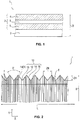
- Fig. 1 Illustrates, comprises an inventive, highly abrasion-resistant technical adhesive tape 1, in particular a cable winding tape 1 for automobile construction that can be wound on itself without an interliner, a tape-shaped, double-layer carrier 2, which is provided on at least one side with a self-adhesive coating 3 made of a pressure-sensitive adhesive consists.
- Pressure-sensitive adhesives can be used here, adhesives known per se, in particular UV-crosslinkable adhesives, whereby these do not require any further modification.
- the carrier 2 comprises a first textile layer layer 4 consisting of a fabric and a second textile layer layer 5, which are firmly connected to one another over the entire surface by an adhesive connection layer 6.
- both layer layers 4, 5, i.e. the first textile layer layer 4 and second textile layer layer 5, consist of a fabric, the fabric of the first textile layer layer 4 and the fabric of the second textile layer layer 5 each having a basis weight in the range of 50 g / m 2 to 300 g / m 2 , preferably 110 g / m 2 to 200 g / m 2 .
- Fig. 2 shows a top view of the surface 4a of the first textile layer 4 forming the back of the tape.
- the fabric of the second textile layer ply 5 can preferably be the same fabric as in the first textile layer ply 4, in particular a fabric that is made of 100 percent polyester fibers consisting of polyethylene terephthalate (PET).
- PET polyethylene terephthalate
- Such a fabric forms a rot-proof carrier 2 and can in particular have a weight per unit area in the range from 50 g / m 2 to 300 g / m 2 , preferably from 110 g / m 2 to 200 g / m 2 .
- the adhesive bonding layer 6 has a weight per unit area in the range from 50 g / m 2 to 300 g / m 2 , with values in the range from 55 g / m 2 to 150 g / m 2 being preferred, and values in the range from 80 g / m 2 being preferred. m 2 to 120 g / m 2 are particularly preferred.
- the adhesive bonding layer 6 can in particular consist of an acrylate or acetate adhesive, preferably of a hotmelt adhesive, as is also used for the Production of the adhesive coating 3 is used.
- a hotmelt adhesive can be produced on the basis of an ethyl-acrylate copolymer, such as an ethyl-butyl-acrylate or an ethyl-ethylene-acrylate, or on the basis of an ethylene-vinyl acetate, ie consist predominantly of these polymers, whereby the polymers can be modified with UV-crosslinkable acrylate resins and / or contain polymerized UV-C photoreactive groups, in particular in side chains.
- the adhesive coating 3 can also have a weight per unit area in the range from approximately 50 g / m 2 to 300 g / m 2 with the preferred ranges specified for the adhesive bonding layer 6.
- the application to the carrier 2 can take place in a technologically advantageous manner using the curtain coating process mentioned above.
- the basis weights of both the adhesive coating 3 and / or the adhesive bonding layer 6 and the two textile layers 4, 5 made of fabric are determined in the usual way according to the standard DIN EN ISO 2286-2 "Textiles coated with rubber or plastic - determination the roll characteristics - Part 2: Determination of the area-related total mass, the area-related mass of the coating and the area-related mass of the carrier ".
- the inventive adhesive tape 1 achieves an abrasion resistance according to LV 312 of at least class E, in particular an abrasion resistance in the range from 5500 to 10,000 strokes, determined on a 5 mm mandrel.
- the adhesive tape according to the invention can be processed manually and by machine and advantageously has a temperature stability of 125 ° C. and more in accordance with LV 312.
- a bond strength between the first textile layer layer 4 and the second textile layer layer 5 of the carrier 2 can be set which is sufficient that it is during processing, in particular when pulling off an adhesive tape roll, or even if necessary, when detaching again from a wrapped object, such as a cable harness, delamination of the layer layers 4, 5 does not occur.
- a laminate adhesive force determined according to DIN EN 1939 between the first textile layer layer 4 and the second textile layer layer 5 of the carrier 2 is greater than 10 N / cm and is preferably in the range from 12 N / cm to 15 N / cm, while that according to DIN
- the bond strength on the tape back 4a determined in accordance with EN 1939 is smaller than the laminate bond strength between the layers 4, 5 and in particular in the range from 4.0 N / cm to 15.0 N / cm, preferably from 5.5 N / cm to 8.0 N / cm.
- An unwinding force determined in accordance with DIN EN 1944 can be in the range from 2 N to 15 N, preferably in the range from 2 N to 9 N.
- the bond strength to steel can assume values in the range from 4.5 N / cm to 15.0 N / cm, preferably from 6.0 N / cm to 11.0 N / cm.
- Table 3 Typical preferred parameters of the fabric structure and the characteristics of the fiber materials for a preferred embodiment of an adhesive tape 1 according to the invention can be found in Table 3 below.
- Table 3 Fabric structure and fiber material description characteristic unit Property / measured value Material of the carrier 2 --- Polyester fabric Basis weight of 4.5 g / m 2 each 155 Fiber type --- 100% polyester (PET) Number of warp threads 7 1 cm 45 Type of yarn warp thread 7 --- Filament, intermingled / textured and solution-dyed Number of filaments per warp thread 7 piece 36 Fineness of the warp threads 7 dtex 56 Fineness of the warp threads in relation to width B 7 dtex / cm 2520 dtex / cm Number of weft threads 8 1 cm 23 Type of yarn weft 8 --- Filament, intermingled and interconnected / textured and spinneret-dyed Number of filaments per weft thread 8 piece Combination of 72 + 36 (total: 108 pieces) Fineness of the weft thread
- Table 4 Technical data of a PET fabric composite adhesive tape 1 according to the invention in comparison test unit invention comparison thickness mm 0.50-0.58 1.0-1.1 Elongation at break % 35-36 25-28 Tear resistance N / cm 90-140 250-290 Adhesive strength - steel N / cm 6.0-11.0 4.3-8.1 - back of the band 4a N / cm 2.0-6.0 3.0-6.9 Unwinding force N / 19mm 3 - 7 3 - 7 Flagging - 30 min mm 0 - 1 0 - 1 - 24 hours mm 0 - 1 0 - 1 Abrasion 5 mm mandrel Strokes 5500-8,200 5300-6200 Laminate Adhesion N / cm 12-15 6 - 8 Noise reduction Great B. E. Lateral tear resistance LV 312 Yes no
- the corresponding parameter values are compared with those of a commercially available adhesive tape with a two-layer carrier made of a PET fabric layer and a nonwoven layer.
- the tear strength is strongly dependent on how the material has been made up.
- Adhesive tapes that have been made up with a normal knife without crosslinking the edges have a tear strength of> 130 N / cm.
- these tapes are very difficult to tear transversely.
- the micro-serration has a tear strength of approx. 125 N / cm.
- the tear resistance can be described as good.
- the tear strength is approx. 100 N / cm and the transverse tearability can be described as very good.
- Table 4a shows how the elongation at break, the tear strength and the tear strength are influenced, ie can be adjusted, by the respective manufacturing process.
- Table 4a test unit Assembly attempt 1 straight knife Assembling experiment with 2 micro serrated knives Assembly attempt 3 macro-serrated knives Elongation at break % 35 30th 28 Tear resistance N / cm 130 125 100 Tearability LV 312 heavy easy very easy test unit Assembly attempt 1 straight knife Assembling experiment with 2 micro serrated knives Assembly attempt 3 macro-serrated knives Tear strength mN 10,000 - 12,000 8,000 - 10,000 5,000 - 8,000
- Table 5 DIN standards New name Date of the currently valid version EN ISO 2286-2 1998-07 Basis weight DIN 53830-3 1981-05 Determination of the fineness of yarn DIN EN 1049-2 1994-02 Determination of the number of threads per unit of length DIN EN 1942 2008-06 thickness DIN EN 14410 2003-06 Breaking strength / elongation DIN EN 1939 2003-12 Bond strength DIN EN 1944 1996-04 Unwinding force DIN EN 21974 DIN EN ISO 1974: 2012-09 2012-09 Tear strength DIN EN ISO 9237 1995-12 Air permeability DIN 53 362 2003-10 Flexural rigidity LV 312 LV 312-1 2009-10 Protection systems for wiring harnesses in motor vehicles, adhesive tapes; Test guideline LV 312 LV 312-1 2009-10 Flagging LV 312 LV 312-1 2009-10 Hand tearability
- the noise attenuation according to LV 312 of class B specified in table 4 means that there is noise attenuation in the range of 2 dB (A) to 5 dB (A) according to LV 312.
- the adhesive tape 1 according to the invention also has a high tear strength, which is expressed in values in the range from 90 N / cm to 200 N / cm, preferably from 100 N / cm to 120 N / cm a test according to DIN EN 14410. As indicated in Table 4, the elongation at break was in the range from 30 percent to 40 percent. It should preferably be greater than 20 percent.
- the comparatively greater laminate adhesive force can be achieved through stronger crosslinking of the adhesive in the adhesive bonding layer 6, for example through a higher radiation output from a UV source used for this purpose, through a temperature which is higher than room temperature up to in the range of 50 ° C. to 140 ° C. or can be achieved by a pressure increased by 0.05 bar to 6.0 bar compared to atmospheric pressure during the lamination process of the textile layers 4, 5, or by a recipe of the adhesive in the adhesive bonding layer 6 that differs from the adhesive recipe in the adhesive coating 3.
- BASF SE offers adhesives for UV crosslinking under the trademark acResin®.
- the polymer chains in these Acrylates contained in adhesives are made from the same acrylate monomers as can be found in dispersion- or solvent-based acrylate pressure-sensitive adhesive systems.
- UV-C light 250 - 260 nm
- polymerized UV-C reactive groups are stimulated to crosslinking reactions with neighboring acrylate chains.
- cross-linking takes place very quickly, but in a precisely controllable manner, and only takes place as long as the UV light acts.
- the polymerized-in photoreactive groups of the polymer particularly those located in side chains of the acResins®, react with any CH group of an adjacent chain.
- a typical size of the adhesive force of an adhesive coating 3, which can be adjusted in this way, is about 6 N / cm according to DIN 1939.
- At least one tape edge 10 of the adhesive tape 1 according to the invention is designed in the form of a pattern deviating from a straight line, which is structured by means of a separation process, as shown in FIG Fig. 2 is shown.
- the band edges 10 are designed as zigzag cut edges, which can be described by a tooth pattern with tooth tips 12, tooth flanks 14, 16 and tooth roots 18.
- a tooth height ZH between the tooth tips 12 and the tooth roots 18 of the pattern can be in the range from 0.1 mm to 3.0 mm, preferably in the range from 0.5 mm to 2.0 mm, being close by the cutting process the outer warp threads 7 lying on the band edge 10 are cut off in the area of the tooth flanks 14, 16 or at least torn in the area of the tooth roots 18.
- the number of warp threads 7 weakened in this way can be in the range from 3 to 12, preferably in the range from 5 to 7, at each edge 10.
- the weft threads 8 are only shortened to different lengths by the separating process.
- FIG. 6 illustrates this process step according to the invention in the production of the inventive adhesive tape 1.
- the inventive adhesive tape 1 has the above-described structure of its edges 10 and is thus easily torn transversely by hand.
- the disk-shaped zigzag knife 20 which can preferably be used in the production of the adhesive tape 1 according to the invention, can be placed on a shaft of a winder known per se as a cutting device 22, as shown in FIG Fig. 6 is shown schematically, and for this purpose has a central assembly opening 24 in its base body 25.
- the zigzag knife 20 has a circumferential zigzag cutting edge 26, the preferred geometry of which in particular Fig. 4 can be found.
- This geometry is formed during separation in the tape edges 10 of the adhesive tape 1 and causes the formation of the tooth pattern with the tooth tips 12, tooth flanks 14, 16 and tooth roots 18, as shown in FIG Fig. 2 shown is.
- the tooth height ZH is found between the tooth tips 12 and the tooth roots 18 of the pattern of the band edge 10 in the geometry of the cutting edge 26 of the zigzag knife 20 in FIG Fig. 4 again, which can then also be dimensioned with the same size.
- a tooth tip angle ⁇ of the cutting edge 26 of the zigzag knife 20 can be in the range from 42 ° to 70 °, and a tooth root width ZB can be in the same range as the tooth height ZH, ie in a preferred range of 0.5 mm up to 2.0 mm.
- At least one cutting device 22 for dividing the carrier material 2 provided with the adhesive coating 3 into strips that run in the longitudinal direction X of the tape is arranged. These strips form each the adhesive tapes 1.
- a stationary blade 27 dips at least on one side into the continuous carrier material 2 provided with the adhesive coating 3.
- At least one zigzag knife 20 is used in the cutting device 22 to produce the tape edges 10 of the adhesive tape 1, the zigzag knife (20) having teeth with a tooth height (ZH) in the range of 0.1 mm to 3.0 mm, micro-prongs with a tooth height (ZH) in the range from 0.1 mm to ⁇ 1.0 mm and macro-prongs with a tooth height (ZH) in the range from 1.0 mm to 3.0 mm are, whereby an elongation at break of at least 20 percent, a tear strength according to DIN EN 14410 in the range of less than 125 N / cm and a tear resistance according to the Elmendorftest of less than 10,000 mN is set in the adhesive tape (1).
- the strips can be separated with particular advantage in that the separate narrow rollers 32 are arranged alternately on different shafts 34, 36, the narrow rollers 32 being driven in the same direction by the shafts 34, 36 assigned to them. At least two narrow rollers 32, preferably a plurality of narrow rollers 32, are arranged on each shaft 34, 36, with the shafts 34, 36 being able to be driven in particular at the same speed, advantageously by a single drive, for example an electric motor.
- the adhesive tapes 1 thus produced and wound on narrow rolls 32 usually have widths B in the range from 9 mm to 50 mm and lengths in the range from 1 m to 100 m, preferably from 2 m to 50 m the individual adhesive tapes 1 are cut usually have widths in the range from 500 mm to 2000 mm and lengths in the range from 300 m to 10,000 m. Since the roll diameters are often subject to technical limitations, longer rolls 30 can be produced with thin carrier materials than with thick materials.
- the invention is not restricted to the exemplary embodiments described, but also includes all embodiments that have the same effect within the meaning of the invention.
- a wave-like pattern could also be selected, or a pattern with a Y-shape, or a knife with so-called T-recesses, which have a targeted edge damage in the millimeter range without departing from the scope of the invention.
- the cutting in narrow rolls can also take place, depending on the material and the thickness of the adhesive tape 1, in a crush cut, a scissors cut, using a laser, an ultrasonic knife or a water jet.
- the cutting device 22 is one in which a circular knife works against a roller.
- a circular knife plunges into a lower knife.
- z. B. in the embodiment according to Table 3 in the fabrics of the first textile layer 4 and / or in the fabrics of the second textile layer 5 each have the warp threads 7 and the weft threads 8 differently, which in the described combination has a positive effect on the advantageous according to the invention Combination of high abrasion resistance, noise dampening and hand tearability, but not necessarily so in every case.
- the carrier 2 from a spinneret-dyed yarn or thread material and to subject the carrier 2 to dispersion dyeing.
- Preferred color combinations produced by the use of suitable color pigments - preferably in polyester material - in the textile layers 4, 5 of an adhesive tape 1 according to the invention are black / black, black / white and white / white.
- the textile layers 4, 5 can therefore each have the same or different colors.
- calendering of the carrier 2 or the first textile layer 4 and / or the second textile layer 5 prior to lamination promotes a reduction in the permeability of the fabric for the adhesive in the adhesive layer 3 and / or in the adhesive bonding layer 6 to express that the air permeability of the fabric measured according to DIN EN ISO 9237 at a test pressure of 500 Pa can preferably be less than 200 l / m 2 s.
Landscapes
- Chemical & Material Sciences (AREA)
- Organic Chemistry (AREA)
- Engineering & Computer Science (AREA)
- Textile Engineering (AREA)
- Adhesive Tapes (AREA)
Description
Die Erfindung betrifft ein hoch abriebfestes technisches Klebeband, insbesondere ein auf sich selbst zu einer Klebebandrolle aufwickelbares Klebeband, vorzugsweise ein Kabelwickelband, mit einem doppellagigem bandförmigem Träger, der auf einer Seite mit einer druckempfindlichen Klebebeschichtung versehen ist, wobei der Träger eine erste, aus einem Gewebe bestehende textile Schichtlage und eine zweite textile Schichtlage umfasst, die vollflächig durch eine Klebverbindungsschicht fest miteinander verbunden sind.The invention relates to a highly abrasion-resistant technical adhesive tape, in particular an adhesive tape that can be wound onto itself to form a roll of adhesive tape, preferably a cable winding tape, with a double-layer tape-shaped carrier which is provided on one side with a pressure-sensitive adhesive coating, the carrier being a first one made of a fabric comprises existing textile layer layer and a second textile layer layer, which are firmly connected to one another over the entire surface by an adhesive bonding layer.
Des Weiteren betrifft die Erfindung ein Verfahren zur Herstellung eines derartigen Klebebandes.The invention also relates to a method for producing such an adhesive tape.
Im Automobilbereich werden Kabelsätze oftmals mit Klebebändern umwickelt, wobei vor allem textile Klebebänder neben der reinen Bündelungsfunktion mittlerweile zahlreiche Zusatzfunktionen, wie den Schutz der Leitungen vor Abrieb oder die Dämpfung von Klapper- oder Vibrationsgeräuschen, übernommen haben. Weit verbreitet ist dabei der Einsatz sowohl von Gewebeklebebändern, als auch von verschiedenartigen Vliesklebebändern.In the automotive sector, cable harnesses are often wrapped with adhesive tapes, with textile tapes in particular, in addition to their pure bundling function, now taking on numerous additional functions, such as protecting cables from abrasion or dampening rattling or vibration noises. The use of fabric adhesive tapes as well as various types of non-woven adhesive tapes is widespread.
Die unterschiedlichen, an Klebebänder gestellten Anforderungen verhalten sich teilweise hinsichtlich bestimmter Basisgrößen des Klebebandes, wie z. B. der Dicke, konträr zueinander. So ist - vorausgesetzt, andere Basisgrößen, wie das Trägermaterial, bleiben konstant - bei einem Klebeband mit zunehmender Dicke zwar mit einer höheren Abriebfestigkeit und Geräuschdämpfung, aber auch mit einer verringerten Flexibilität und einer Verschlechterung der Handeinreißbarkeit sowie des Flagging-Verhaltens zu rechnen.The different requirements placed on adhesive tapes are partly related to certain basic sizes of the adhesive tape, such as e.g. B. the thickness, contrary to each other. So - provided other basic parameters, such as the carrier material, remain constant - with an adhesive tape with increasing thickness A higher abrasion resistance and noise damping, but also a reduced flexibility and a deterioration in hand tearability and flagging behavior can be expected.
Die Prüfung von Klebebändern für die Bewicklung von Kabelsätzen erfolgt in der Automobilindustrie zumeist nach umfangreichen Normenwerken, wie sie z. B. in der LV 312 "
So wird die Abriebbeständigkeit nach LV 312 in Anlehnung an DIN ISO 6722 bestimmt, indem das Klebeband zunächst auf einen Dorn (Metallstab) mit 5 oder 10 mm Durchmesser aufgeklebt wird. Mit einem Schabwerkzeug, das einen Nadeldurchmesser von 0,45 mm aufweist, wird dann unter einer Gewichtskraft von 7 N die Anzahl der Hübe bestimmt, die benötigt wird, um das Klebeband durchzuscheuern. Hinsichtlich der Abriebbeständigkeit ist dabei in der LV 312 die in der nachstehenden Tabelle 1 wiedergegebene Klassifizierung vorgesehen.
Hinsichtlich der Geräuschdämpfung sieht die LV 312 die in der nachstehenden Tabelle 2 wiedergegebene Klassifizierung vor.
Als weitere anwendungstechnisch wichtige Prüfungen sind in der genannten Richtlinie beispielsweise auch Prüfmethoden für die thermische Beständigkeit, die Kompatibilität von Klebebändern mit elektrischen Fahrzeugleitungen sowie für die Chemikalienbeständigkeit, das Fogging- sowie für das Flagging-Verhalten beschrieben. Unter Flagging versteht man dabei eine Ablösung insbesondere schraubenförmig um einen Kabelsatz gewickelter Bänder, so dass deren Enden abstehen und, um dies zu vermeiden, jeweils beim Einsatz fixiert werden müssen.As further tests that are important in application technology, the above-mentioned guideline also describes, for example, test methods for thermal resistance, the compatibility of adhesive tapes with electrical vehicle cables and for chemical resistance, fogging and flagging behavior. In this context, flagging is understood to mean a detachment, in particular helically wound around a set of cables, so that their ends protrude and, in order to avoid this, have to be fixed during use.
Es sind, um den unterschiedlichen Beanspruchungen in der Praxis gerecht zu werden, gemäß dem Stand der Technik zahlreiche technische Lösungen für Klebebänder bekannt, bei denen in der Regel einer, teilweise auch zwei oder mehr, der geforderten Eigenschaften besondere Bedeutung beigemessen wird, während andere Eigenschaften als weniger bedeutsam in den Hintergrund treten, wobei ein eigentlich nicht als optimal angesehener Wertebereich für diese Parameter toleriert wird.In order to do justice to the different demands in practice, numerous technical solutions for adhesive tapes are known according to the prior art, in which, as a rule, one, sometimes two or more, of the required properties are given particular importance, while other properties are assigned take a back seat as less significant, with a value range that is actually not regarded as optimal being tolerated for these parameters.
Aus der
Ein doppellagiges Klebeband der eingangs genannten Art ist auch aus der
Der vorliegenden Erfindung liegt die Aufgabe zugrunde, ein Klebeband der eingangs genannten Art mit doppellagigem Träger zu schaffen, das bei hoher Abriebfestigkeit, insbesondere mit einer Abriebfestigkeit nach Klasse E gemäß LV 312, die vorzugsweise am 5-mm-Dorn bestimmt wird, sowohl manuell, als auch maschinell leicht verarbeitbar ist und eine Handeinreißbarkeit aufweist. Dabei soll das erfindungsgemäße Klebeband bevorzugt bei Vorhandensein eines verrottungsfesten Trägers auch schmiegsam und flexibel sein, ein im Vergleich mit Klebebändern gemäß dem vorstehend genannten Stand der Technik verbessertes Flagging-Verhalten zeigen, eine hohe Klebkraft aufweisen und mindestens die Anforderungen gemäß der Geräuschdämpfungsklasse B nach LV 312 erfüllen.The present invention is based on the object of creating an adhesive tape of the type mentioned at the outset with a double-layer carrier which, with high abrasion resistance, in particular with an abrasion resistance according to class E according to LV 312, which is preferably determined on the 5 mm mandrel, both manually, and can be easily processed by machine and can be torn by hand. The adhesive tape according to the invention should preferably also be pliable and flexible in the presence of a rot-proof backing, show an improved flagging behavior compared to adhesive tapes according to the prior art mentioned above, have a high adhesive strength and at least meet the requirements of noise reduction class B according to LV 312 fulfill.
Erfindungsgemäß wird dies dadurch erreicht, dass die zweite textile Schichtlage aus einem Gewebe besteht, wobei das Gewebe der ersten textilen Schichtlage und das Gewebe der zweiten textilen Schichtlage jeweils ein Flächengewicht im Bereich von 50 g/ m2 bis 300 g/m2 aufweist, wobei die Klebverbindungsschicht ein Flächengewicht im Bereich von 50 g/m2 bis 300 g/m2 aufweist und wobei das Klebeband eine Dicke (D) im Bereich von 0,55 mm bis 1,0 mm aufweist und mindestens eine Bandkante in Form eines von einer geraden Linie abweichenden Musters ausgeführt ist, welches mittels eines Trennprozesses durch eine Trenneinrichtung, die Mikrozacken mit einer Zahnhöhe (ZH) im Bereich von 0,1 mm bis <1,0 mm und Makrozacken mit einer Zahnhöhe (ZH) im Bereich von 1,0 mm bis 3,0 mm aufweist, derart strukturiert ist, dass eine Reißfestigkeit bei einer Prüfung nach DIN EN 14410 kleiner ist als 125 N/cm, wobei eine Reißdehnung mindestens 20 Prozent beträgt und eine Weiterreißfestigkeit gemäß Elmendorftest kleiner ist als 10.000 mN.According to the invention, this is achieved in that the second textile layer layer consists of a fabric, the fabric of the first textile layer layer and the fabric of the second textile layer layer each having a weight per unit area in the range from 50 g / m 2 to 300 g / m 2 , with the adhesive bonding layer has a basis weight in the range from 50 g / m 2 to 300 g / m 2 and wherein the adhesive tape has a thickness (D) in the range from 0.55 mm to 1.0 mm and at least one tape edge in the form of one of one straight line deviating pattern is carried out, which by means of a separating process by a separating device, the micro-peaks with a tooth height (ZH) in the range of 0.1 mm to <1.0 mm and macro-peaks with a tooth height (ZH) in the range of 1.0 mm to 3.0 mm, is structured in such a way that a tear strength in a test according to DIN EN 14410 is less than 125 N / cm, an elongation at break being at least 20 percent and a tear strength according to Elmendorfte st is less than 10,000 mN.
Mit dem erfindungsgemäßen Klebeband werden so unter Verzicht auf eine mit der ersten textilen Schichtlage verbundene Flächengebildeschicht, die aus einer offenen dreidimensionalen Struktur, wie einem Vlies oder einem Schaumstoff, besteht, sowie unter Verzicht auf eine gerade Schnittkante bei gegebener Handeinreißbarkeit eine Geräuschdämpfung mindestens der Klasse B sowie exzellente Werte der Abriebfestigkeit erzielt. Insbesondere wird eine Abriebfestigkeit gemäß der Klasse E nach LV 312 erreicht.With the adhesive tape according to the invention, dispensing with a sheet-like structure layer connected to the first textile layer, consists of an open three-dimensional structure, such as a fleece or a foam, as well as dispensing with a straight cut edge with a given hand tearability Noise attenuation of at least class B as well as excellent values of abrasion resistance achieved. In particular, an abrasion resistance according to class E according to LV 312 is achieved.
Bei gleicher erreichter Hubzahl bis zum Abriebgrenzwert liegt dabei die Abriebfestigkeit am 5-mm-Dorn höher als an einem 10-mm-Dorn, da bei einer gegebenen Abriebfestigkeit an einem solchen Dorn der Abriebgrenzwert eher - also schon bei einer geringeren Hubzahl - erreicht wird als am 10-mm-Dorn. So ist es möglich, dass ein Gewebe, das am Dorn mit 10 mm Durchmesser eine Abriebfestigkeit nach einer bestimmten Klasse erreicht, entsprechend der Prüfung am 5-mm-Dorn in eine Klasse tiefer eingestuft werden muss. Dies ist jedoch bei einem erfindungsgemäßen Klebeband nicht der Fall: Die Abriebklasse E wird sowohl am 10-mm-Dorn, als auch am 5-mm-Dorn erreicht.With the same number of strokes up to the abrasion limit value, the abrasion resistance on the 5 mm mandrel is higher than on a 10 mm mandrel, since with a given abrasion resistance on such a mandrel, the abrasion limit value is reached sooner - i.e. even with a lower number of strokes on the 10 mm mandrel. It is possible that a fabric that achieves an abrasion resistance according to a certain class on the mandrel with a 10 mm diameter must be classified in a class lower according to the test on the 5 mm mandrel. However, this is not the case with an inventive adhesive tape: abrasion class E is achieved on both the 10 mm mandrel and the 5 mm mandrel.
Das erfindungsgemäße Klebeband ist deutlich schmiegsamer als die eingangs beschriebenen bekannten Klebebänder. Es hat diesen gegenüber eine geringere Neigung zum Flagging. Eine manuelle und maschinelle Verarbeitung ist gegeben. Die entsprechenden Parameter liegen in einem Bereich, wie er auch für einlagige Klebebänder charakteristisch ist.The adhesive tape of the invention is significantly more pliable than the known adhesive tapes described at the outset. Compared to these, it has a lower tendency to flagging. Manual and machine processing is available. The corresponding parameters are in a range that is also characteristic of single-ply adhesive tapes.
Die Vorteilhaftigkeit der Erfindung zeigt sich dabei im Besonderen, wenn der Träger aus einem verrottungsfesten textilen Träger, wie beispielsweise aus einem Polyamid- oder Polyester-Gewebe, besteht, wodurch insbesondere neben der angestrebten Abriebfestigkeit die geforderte Reißfestigkeit gewährleistet werden kann. Aufgrund dieser Eigenschaften eignet sich das erfindungsgemäße Klebeband ausgezeichnet zum Umwickeln von Kabelsätzen.The advantage of the invention is particularly evident when the carrier consists of a rot-proof textile carrier such as a polyamide or polyester fabric, whereby the required tear resistance can be guaranteed in addition to the desired abrasion resistance. Because of these properties, the adhesive tape according to the invention is excellently suited for wrapping cable harnesses.
Das erfindungsgemäße Klebeband kann dabei insbesondere eine Dicke im Bereich von von 0,55 mm bis 0,75 mm, aufweisen.The adhesive tape according to the invention can in particular have a thickness in the range from 0.55 mm to 0.75 mm.
Durch die Muster-Strukturierung einer oder insbesondere beider Bandkanten, welche bei der Bandherstellung mittels eines Trennprozesses ausgeführt werden kann, kann dabei - auch bei einem anfänglich zunächst nicht handeinreißbaren Träger - überraschenderweise bei dieser Dicke dennoch eine Handeinreißbarkeit in Querrichtung des Bandes erzielt werden.Due to the pattern structuring of one or in particular both tape edges, which can be carried out by means of a separation process during tape production, surprisingly hand-tearability in the transverse direction of the tape can still be achieved with this thickness - even with a carrier that is initially not hand-tearable.
Insbesondere kann dabei vorgesehen sein, dass beide Bandkanten als Zick-Zack-Schnittkanten ausgebildet sind, welche durch ein Zahnmuster mit Zahnspitzen, Zahnflanken und Zahnfüßen beschrieben werden kann. Dabei kann die Zahnhöhe des Musters im Bereich von 0,1 mm (0,1 mm bis <1,0 mm - Mikrozacken) bis 3,0 mm (1,0 mm bis 3,0 mm - Makrozacken) liegen, wobei durch den Trennprozess in der Nähe der Bandkante liegende äußere Kettfäden im Bereich der Zahnflanken zerschnitten oder im Bereich der Zahnfüße zumindest angerissen werden. Die Anzahl der solchermaßen geschwächten Kettfäden kann im Bereich von > 1 bis 15, bevorzugt im Bereich von 2 bis 12, besonders bevorzugt im Bereich 6 bis 11, liegen. Die Schussfäden werden durch den Trennprozess auf unterschiedliche Längen gekürzt. Hierzu kann ein Zackenschnittmesser eingesetzt werden, wie es an sich aus der
Die Herstellung eines solchen Klebebandes umfasst folgende Schritte:The production of such an adhesive tape comprises the following steps:
Insbesondere für Polyester-Gewebe-Träger können erfindungsgemäß bevorzugt Fadenkonstruktionen mit 45 ± 3 Kettfäden und 23 ± 2 Schussfäden eingesetzt werden, wobei der Einsatz von bevorzugt ungleichartigen Fäden in Kette und Schuss ebenfalls als günstig im Hinblick auf eine erhöhte Abriebbeständigkeit angesehen werden kann.According to the invention, thread constructions with 45 ± 3 warp threads and 23 ± 2 weft threads can preferably be used for polyester fabric carriers in particular, whereby the use of preferably dissimilar threads in warp and weft can also be regarded as beneficial in terms of increased abrasion resistance.
Die Feinheit der Kettfäden kann dabei unter 100 dtex, insbesondere bei 56 dtex, und die der Schussfäden bei über 400 dtex, insbesondere bei 557 dtex, liegen, wobei die Feinheit der Kettfäden zur Feinheit der Schussfäden in einem als optimal angesehenen Verhältnis von 1 : 8 - 11, vorzugsweise von 1 : 10, steht. Kettfäden und Schussfäden können sich dabei bevorzugt auch aus einer jeweils unterschiedlichen Anzahl von Filamenten zusammensetzen. Im Allgemeinen ist dabei eine Anzahl im Bereich von 24 bis 144 Filamenten pro Faden möglich, wobei aber mit zunehmender Filamentzahl von einer Verringerung der Abriebfestigkeit auszugehen ist.The fineness of the warp threads can be below 100 dtex, in particular 56 dtex, and that of the weft threads over 400 dtex, in particular 557 dtex, with the The fineness of the warp threads to the fineness of the weft threads is in an optimal ratio of 1: 8-11, preferably 1:10. Warp threads and weft threads can preferably also be composed of a different number of filaments in each case. In general, a number in the range from 24 to 144 filaments per thread is possible, but with an increasing number of filaments, a reduction in abrasion resistance can be assumed.
Vorteilhaft erhöhend auf die Abriebbeständigkeit wirkt sich auch der Einsatz von texturierten Fäden aus. Mit Texturieren bezeichnet man in der Textilindustrie einen Vorgang, durch den Chemiefasern dauerhaft gekräuselt werden. Die glatten synthetischen Fäden erhalten durch diese Veredelung einen naturfaserähnlichen Charakter und einen textilen Griff. Das Texturieren geschieht meist unter dem Einfluss von Hitze und Druck, wobei eine Thermoplastizität der Fasern ausgenutzt wird. Durch eine Kräuselung der Fasern bei der Texturierung werden Faserschlingen erzeugt, durch die es zu einer Volumenzunahme kommt, wobei die elastische Dehnbarkeit ansteigt, während sich die Wärmeleitfähigkeit vermindert.The use of textured threads also has an advantageous effect on increasing the abrasion resistance. In the textile industry, texturing is a process by which man-made fibers are permanently crimped. This finishing gives the smooth synthetic threads a natural fiber-like character and a textile feel. Texturing usually takes place under the influence of heat and pressure, whereby the thermoplasticity of the fibers is exploited. By crimping the fibers during texturing, fiber loops are created, which lead to an increase in volume, the elastic extensibility increasing while the thermal conductivity is reduced.
Zur Durchführung des Texturierens sind verschiedene, insbesondere mechanische, mechanisch-thermische und chemisch-thermische Verfahren bekannt. So wird bei dem sogenannten Falschdrahtverfahren ein Faden mit bis zu 1000 Drehungen/m verdrillt und heiß fixiert. Nach dem Zurückdrehen bleibt in den einzelnen Filamenten eine fixierte Spiralstruktur erhalten. Bei der Stauchkräuselung wird ein Faserverbund durch beheizte Walzen in eine Kammer mit keilförmig angeordneten Wänden gepresst und dadurch gestaucht und gekräuselt, wobei die Kräuselung durch die Kammerheizung fixiert wird. Bei der Blastexturierung wird ein Filamentgarn durch eine Düse geführt, durch die gleichzeitig Druckluft gepresst wird. Beim Austritt aus der Düse verwirbelt die Luft, löst das Garn dadurch teilweise in seine Einzelfilamente auf und verschlauft sie danach wieder, wonach in einer Fixierzone eine abschließende Stabilisierung erfolgt, die auch mit einer Verfestigung und Schrumpfung verbunden ist.Various, in particular mechanical, mechanical-thermal and chemical-thermal methods are known for performing texturing. In the so-called false twisting process, a thread is twisted with up to 1000 turns / m and fixed in place. After turning back, a fixed spiral structure is retained in the individual filaments. In compression crimping, a fiber composite is pressed by heated rollers into a chamber with walls arranged in a wedge shape and thereby compressed and crimped, the crimp being fixed by the chamber heating. With blow texturing, a filament yarn is passed through a nozzle through which compressed air is pressed at the same time. When it exits the nozzle, the air swirls, thereby partially dissolving the yarn into its individual filaments and then looping them again, after which a final stabilization takes place in a fixing zone, which is also associated with solidification and shrinkage.
Filamentgarne, insbesondere Polyestergarne, sind im Handel in Titerbereichen von insbesondere 33 dtex bis 660 dtex als Glattgarn in verschiedenen Formen erhältlich, so als FDY - Fully Drawn Yarn bzw. FOY - Fully Oriented Yarn, oder als POY - Partially Oriented Yarn; aber auch texturiert: DTY - Drawn Textured Yarn. In den Fäden der Gewebe, die zur Bildung des Trägers eingesetzt werden, können mit Vorteil Filamente der verschiedenen Garnformen kombiniert sein. So können insbesondere, wie im speziellen Ausführungsbeispiel noch dargestellt, Schussfäden jeweils aus einer Kombination von FDY- und DTY-Filamenten bestehen, wodurch der Fadenzusammenhalt erhöht wird, was insbesondere bei dickeren Fäden, also Fäden einer höheren Feinheit, von Bedeutung ist.Filament yarns, in particular polyester yarns, are commercially available in denier ranges from in particular 33 dtex to 660 dtex as flat yarn in various forms, for example as FDY - Fully Drawn Yarn or FOY - Fully Oriented Yarn, or as POY - Partially Oriented Yarn; but also textured: DTY - Drawn Textured Yarn. In the threads of the fabric which are used to form the carrier, filaments of the various yarn forms can advantageously be combined. In particular, as shown in the special embodiment, weft threads can each consist of a combination of FDY and DTY filaments, whereby the thread cohesion is increased, which is particularly important in the case of thicker threads, i.e. threads of a higher fineness.
Außerdem kann mit Vorteil auch vorgesehen sein, dass in dem Gewebe der ersten textilen Schichtlage und/oder in dem Gewebe der zweiten textilen Schichtlage jeweils die Kettfäden und/oder die Schussfäden intermingelt sind, wobei insbesondere 50 bis 150 Intermingelungspunkte pro Meter vorliegen. Das Intermingeln - auch Interlacing genannt - ist eine Zusatzausrüstung der Fäden, bei der die Fäden durch eine Verwirbelung mit Luft punktuell verflochten werden. Dabei wird der Zusammenhalt der einzelnen Filamente nicht durch ein Verdrehen, sondern durch eine Verschlingung der Filamente erreicht. Das Intermingeln kann mit glatten Fäden durchgeführt werden, es ist aber auch möglich, und erfindungsgemäß bevorzugt, ein Intermingeln im direkten Anschluss an ein Texturieren der Fäden durchzuführen.In addition, it can advantageously also be provided that the warp threads and / or the weft threads are intermingled in the fabric of the first textile layer layer and / or in the fabric of the second textile layer layer, in particular 50 to 150 intermingling points per meter. Interlacing - also known as interlacing - is an additional feature of the threads, in which the threads are interlaced at certain points by being swirled with air. The cohesion of the individual filaments is not achieved by twisting, but by entangling the filaments. Intermingling can be carried out with smooth threads, but it is also possible, and according to the invention preferred, to carry out intermingling directly after texturing the threads.
Die Klebverbindungsschicht kann dabei mit Vorteil aus einem Hotmeltklebstoff bestehen, insbesondere aus einem Hotmeltklebstoff, der überwiegend aus einem Ethyl-Acrylat-Copolymer, wie einem Ethyl-Butyl-Acrylat oder einem Ethyl-Ethylen-Acrylat, oder überwiegend aus einem Ethylen-Vinyl-Acetat-Copolymer (EVA), besteht, wobei das jeweilige Copolymer vorzugsweise mit UV-vernetzbaren Acrylatharzen modifiziert ist und/oder einpolymerisierte UV-C-fotoreaktive Gruppen insbesondere in der Seitenkette enthält.The adhesive bonding layer can advantageously consist of a hotmelt adhesive, in particular a hotmelt adhesive which is predominantly composed of an ethyl acrylate copolymer, such as an ethyl butyl acrylate or an ethyl ethylene acrylate, or predominantly of an ethylene vinyl acetate -Copolymer (EVA), the respective copolymer preferably with UV-crosslinkable acrylate resins is modified and / or contains polymerized UV-C photoreactive groups, in particular in the side chain.
Der Klebstoff trägt einerseits zur Abrieberhöhung bei, andererseits sind dadurch eine Düsenbeschichtung des Trägers und Herstellung des erfindungsgemäßen Klebebandes mittels konventioneller Hotmelt-Coater möglich, die üblicherweise für Dispersions- und lösemittelhaltige Kleber ausgelegt sind.On the one hand, the adhesive contributes to the increase in abrasion; on the other hand, it enables nozzle coating of the carrier and production of the adhesive tape according to the invention by means of conventional hotmelt coaters, which are usually designed for dispersion and solvent-based adhesives.
Der Klebstoff kann insbesondere in einem drucklosen Beschichtungsverfahren, wie dem sogenannten "Curtain Coating-Verfahren", aufgebracht werden. Gemäß diesem Verfahren fällt ein geschlossener Klebstofffilm auf das Substrat. Dadurch wird eine gleichmäßige Dicke und damit Grammatur der Klebstoffschicht erreicht. Es wird nur soviel Klebstoff aufgetragen, wie unbedingt benötigt wird.The adhesive can in particular be applied in a pressureless coating process, such as the so-called "curtain coating process". According to this method, a closed film of adhesive falls onto the substrate. This ensures that the adhesive layer has a uniform thickness and thus grammage. Only as much adhesive is applied as is absolutely necessary.
Dadurch kann erfindungsgemäß das Flächengewicht sowohl der Klebverbindungsschicht im Bereich von 50 bis 300 g/m2, als auch der Klebebeschichtung bevorzugt im Bereich von etwa 50 g/m2 bis 300 g/m2, vorzugsweise im Bereich von 55 g/m2 bis 150 g/m2, genau eingestellt werden. Die Grammatur der Klebverbindungsschicht und der Klebebeschichtung können auf die gleiche Größe eingestellt werden. Bei alternativen Produktaufbauten können auch differente Kleberaufträge der Klebverbindungsschicht und der Klebebeschichtung eingestellt werden.As a result, according to the invention, the weight per unit area of both the adhesive bond layer in the range from 50 to 300 g / m2, and of the adhesive coating, preferably in the range from about 50 g / m2 to 300 g / m2, preferably in the range from 55 g / m2 to 150 g / m2 to be set precisely. The grammage of the adhesive bonding layer and the adhesive coating can be adjusted to the same size. In the case of alternative product structures, different adhesive applications of the adhesive bonding layer and the adhesive coating can also be set.
Insbesondere ist es dabei auch möglich, eine im Rahmen der Erfindung als optimal betrachtete, nach DIN EN 1939 (Stand 2003) bestimmte Laminathaftkraft zwischen der ersten textilen Schichtlage und der zweiten textilen Schichtlage des Trägers auf einen Wert einzustellen, der größer ist als 10 N/cm.In particular, it is also possible in the context of the invention to set a laminate adhesion force between the first textile layer layer and the second textile layer layer of the carrier, which is considered to be optimal in accordance with DIN EN 1939 (status 2003), to a value that is greater than 10 N / cm.
Der Verbund mittels des genannten Hotmeltklebstoffs wirkt sich gegenüber dem Einsatz der anderen erwähnten Klebstoffe mit steigendem Flächengewicht im erfindungsgemäß beanspruchten Bereich vorteilhafterweise auch überproportional erhöhend auf die Abriebfestigkeit aus.Compared to the use of the other adhesives mentioned, the bond by means of the hotmelt adhesive mentioned, with increasing weight per unit area in the area claimed according to the invention, advantageously also has a disproportionately higher effect on the abrasion resistance.
Die Laminierung kann Inline oder Offline in einem separaten Arbeitsgang erfolgen. Das Trägermaterial der Mutterrolle, das aus dem Laminat besteht, ist je nach Materialkombination bedingt handeinreißbar oder nicht handeinreißbar.The lamination can be done inline or offline in a separate operation. The carrier material of the parent roll, which consists of the laminate, is, depending on the material combination, hand-tearable to a limited extent or not hand-tearable.
Die Herstellung des erfindungsgemäßen Klebebandes umfasst dabei ein Laminieren der Gewebeschichten des Trägers aneinander, ein Auftragen der Klebeschicht auf mindestens eine Seite des Laminats, wobei insbesondere nach dem Laminieren das Gewebe bzw. das Klebeband nach dem Auftragen mit der Klebeschicht noch nicht quer einreißbar ist, ein Aufwickeln zu einer Mutterrolle großer Breite und - in einem abschließenden Fertigungsschritt - den Zuschnitt der Mutterolle zu verkaufsfähigen handelsüblichen Schmalrollen, wobei die Mutterrolle mittels eines Rollenschneiders getrennt wird. Bei dieser Konfektionierung wird insbesondere durch den Einsatz eines Zick-Zack-Messers das Klebeband mit der Kantenstrukturierung versehen und wird so per Hand quer einreißbar.The production of the adhesive tape according to the invention comprises lamination of the fabric layers of the carrier to one another, application of the adhesive layer to at least one side of the laminate, with the fabric or the adhesive tape not yet being tearable transversely after the lamination with the adhesive layer Winding up into a large-width parent roll and - in a final production step - cutting the parent roll into commercially available narrow rolls that can be sold, the parent roll being separated by means of a winder. With this assembly, the adhesive tape is provided with the edge structure, in particular through the use of a zigzag knife, and can thus be torn transversely by hand.
Bei der Konfektionierung der Mutterrolle zur Schmalrolle wird durch den Einsatz eines geeigneten Konfektionierungsverfahrens die Handeinreißbarkeit der Schmalrolle optimiert, dahingehend, dass nach der Konfektionierung die Schmalrolle eine gute bis bedingte Handreinreißbarkeit aufweist. Dieses wird zum Beispiel durch Einsatz eines Rollenschneiders, der mit Zick-Zack-Kreismesser ausgerüstet ist, erreicht. Derartige Zick-Zack-Messer haben eine Kantenstrukturierung unterschiedlicher Art. In der
Durch die gezielte Randverletzung wird die Handeinreißbarkeit verbessert. Außerdem kann die Reißfestigkeit durch die Art der Bandkante in Form eines von einer geraden Linie abweichenden Musters, welches mittels des Trennprozesses strukturiert ist, gezielt verringert werden, wobei sich die Reißfestigkeit um bis zu 40 % gegenüber einem Ausgangswert, der nach DIN EN 14410 an einem Material ohne Randstrukturierung gemessen wird, verringerbar ist. Durch den Zick-Zack-Randbeschnitt werden auch andere Klebebandeigenschaften, wie z.B. Bruchkraft, Reißdehnung und Weiterreißfestigkeit beeinflusst.The targeted damage to the edge improves the hand tearability. In addition, the tear resistance can be specifically reduced by the type of tape edge in the form of a pattern deviating from a straight line, which is structured by means of the separation process, whereby the tear resistance is up to 40% compared to an initial value, which according to DIN EN 14410 on a Material is measured without edge structuring, can be reduced. The zigzag edge trim also influences other adhesive tape properties, such as breaking strength, elongation at break and tear strength.
Es besteht auch die Möglichkeit, für die Herstellung der Schmalrollen Umroll- und Schneidautomaten mit Messerstichel einzusetzen.It is also possible to use automatic rewinding and cutting machines with a knife for the production of the narrow rolls.
Weitere vorteilhafte Ausgestaltungsmerkmale der Erfindung sind in den Unteransprüchen sowie der folgenden Beschreibung enthalten. Anhand eines durch die beiliegende Zeichnung veranschaulichten erfindungsgemäßen Ausführungsbeispiels und eines Vergleichsbeispiels wird die Erfindung näher erläutert. Dabei zeigen:
- Fig. 1
- in einer Querschnittsdarstellung, eine Ausführung eines erfindungsgemäßen Klebebandes,
- Fig. 2
- in einer Aufsicht, einen Ausschnitt auf eine Ausführung eines erfindungsgemäßen Klebebandes,
- Fig. 3
- eine perspektivische Ansicht eines zur Herstellung eines erfindungsgemäßen Klebebandes einsetzbaren Messers,
- Fig. 4
- eine Aufsicht in Richtung des Pfeiles IV in
Fig. 3 und 5 auf eine Schneidkante eines zur Herstellung eines erfindungsgemäßen Klebebandes einsetzbaren Messers, - Fig. 5
- einen Querschnitt durch ein zur Herstellung eines erfindungsgemäßen Klebebandes einsetzbaren Messers, wobei die Peripherie des Messers (Einzelheit V) derart geschnitten dargestellt ist, wie sich dies aus der Linie V-V in
Fig. 4 ergibt, - Fig. 6
- eine schematisierte perspektivische Darstellung zur Veranschaulichung des erfindungsgemäßen Verfahrensschrittes bei der Herstellung eines erfindungsgemäßen Klebebandes.
- Fig. 1
- in a cross-sectional view, an embodiment of an adhesive tape according to the invention,
- Fig. 2
- in a plan view, a section of an embodiment of an adhesive tape according to the invention,
- Fig. 3
- a perspective view of a knife that can be used to produce an adhesive tape according to the invention,
- Fig. 4
- a plan view in the direction of arrow IV in
Figures 3 and 5 on a cutting edge of a knife that can be used to produce an adhesive tape according to the invention, - Fig. 5
- a cross-section through a knife that can be used to produce an adhesive tape according to the invention, the periphery of the knife (detail V) being shown in section as can be seen from the line VV in FIG
Fig. 4 results, - Fig. 6
- a schematic perspective representation to illustrate the process step according to the invention in the production of an adhesive tape according to the invention.
Zu der anschließenden Beschreibung wird ausdrücklich betont, dass die Erfindung nicht auf das Ausführungsbeispiel und dabei auch nicht auf alle oder mehrere Merkmale von beschriebenen Merkmalskombinationen beschränkt ist. Vielmehr kann jedes einzelne Teilmerkmal des Ausführungsbeispiels auch losgelöst von allen anderen im Zusammenhang damit beschriebenen Teilmerkmalen für sich und auch in Kombination mit beliebigen anderen Merkmalen eine erfinderische Bedeutung haben.In relation to the following description, it is expressly emphasized that the invention is not limited to the exemplary embodiment and also not to all or several features of the described feature combinations. Rather, each individual sub-feature of the exemplary embodiment can also have an inventive significance in isolation from all other sub-features described in connection therewith and also in combination with any other features.
In den Figuren der Zeichnung sind gleiche und einander entsprechende Teile auch stets mit denselben Bezugszeichen versehen, so dass sie in der Regel auch jeweils nur einmal beschrieben werden.In the figures of the drawing, the same and corresponding parts are always provided with the same reference numerals, so that they are usually only described once.
Wie zunächst
Der Träger 2 umfasst eine erste, aus einem Gewebe bestehende textile Schichtlage 4 und eine zweite textile Schichtlage 5, die vollfächig durch eine Klebverbindungsschicht 6 fest miteinander verbunden sind. Erfindungsgemäß ist vorgesehen, dass beide Schichtlagen 4, 5, also die erste textile Schichtlage 4 und zweite textile Schichtlage 5, aus einem Gewebe bestehen, wobei das Gewebe der ersten textilen Schichtlage 4 und das Gewebe der zweiten textilen Schichtlage 5 jeweils ein Flächengewicht im Bereich von 50 g/m2 bis 300 g/m2, vorzugsweise 110 g/m2 bis 200 g/m2, aufweist.The carrier 2 comprises a first
Bevorzugt kann es sich bei dem Gewebe der zweiten textilen Schichtlage 5 um das gleiche Gewebe handeln wie in der ersten textilen Schichtlage 4, insbesondere um ein Gewebe, das zu 100 Prozent aus Polyethylenterephthalat (PET) bestehenden Polyesterfasern gebildet ist. Ein solches Gewebe bildet einen verrottungsfesten Träger 2 und kann insbesondere jeweils ein Flächengewicht im Bereich von 50 g/m2 bis 300 g/m2, vorzugsweise von 110 g/m2 bis 200 g/m2, aufweisen.The fabric of the second textile layer ply 5 can preferably be the same fabric as in the first
Die Klebverbindungsschicht 6 weist erfindungsgemäß ein Flächengewicht im Bereich von 50 g/m2 bis 300 g/m2 auf, wobei hier Werte im Bereich von 55 g/m2 bis 150 g/m2 bevorzugt, und Werte im Bereich von 80 g/m2 bis 120 g/m2 besonders bevorzugt sind.According to the invention, the
Die Klebverbindungsschicht 6 kann insbesondere aus einem Acrylat- oder Acetatklebstoff bestehen, vorzugsweise aus einem Hotmeltklebstoff, wie er auch für die Herstellung der Klebebeschichtung 3 zur Anwendung kommt. Ein derartiger Hotmeltklebstoff kann auf der Basis eines Ethyl-Acrylat-Copolymers, wie einem Ethyl-Butyl-Acrylat oder einem Ethyl-Ethylen-Acrylat, oder auf der Basis eines Ethylen-Vinyl-Acetates hergestellt sein, d. h. überwiegend aus diesen Polymeren bestehen, wobei die Polymere mit UV-vernetzbaren Acrylatharzen modifiziert sein und/oder einpolymerisierte UV-C-fotoreaktive Gruppen, insbesondere in Seitenketten, enthalten können.The
Auch die Klebebeschichtung 3 kann ein Flächengewicht im Bereich von etwa 50 g/m2 bis 300 g/m2 mit den für die Klebeverbindungsschicht 6 angegebenen Vorzugsbereichen aufweisen. Die Auftragung auf den Träger 2 kann in technologisch vorteilhafter Weise unter Anwendung des oben erwähnten Curtain-Coating-Verfahrens erfolgen.The
Die Bestimmung der Flächengewichte sowohl der Klebebeschichtung 3 und/oder der Klebverbindungsschicht 6, als auch der beiden aus Gewebe bestehenden textilen Schichtlagen 4, 5 erfolgt dabei in üblicher Weise nach der Norm DIN EN ISO 2286-2 "Mit Kautschuk oder Kunststoff beschichtete Textilien - Bestimmung der Rollencharakteristik - Teil 2: Bestimmung der flächenbezogenen Gesamtmasse, der flächenbezogenen Masse der Beschichtung und der flächenbezogenen Masse des Trägers".The basis weights of both the
Bei einer Dicke D, die mindestens bei 0,50 mm liegt, vorzugsweise bei einer Dicke D im Bereich von 0,50 mm bis 1,0 mm, besonders bevorzugt bei einer Dicke im Bereich von 0,55 mm bis 0,75 mm, erreicht das erfindungsgemäße Klebeband 1 dabei eine Abriebbeständigkeit nach LV 312 von mindestens der Klasse E, insbesondere eine Abriebbeständigkeit im Bereich von 5500 bis 10000 Hüben, bestimmt an einem 5-mm-Dorn.With a thickness D that is at least 0.50 mm, preferably with a thickness D in the range from 0.50 mm to 1.0 mm, particularly preferably with a thickness in the range from 0.55 mm to 0.75 mm, the inventive adhesive tape 1 achieves an abrasion resistance according to LV 312 of at least class E, in particular an abrasion resistance in the range from 5500 to 10,000 strokes, determined on a 5 mm mandrel.
Das erfindungsgemäße Klebeband ist dabei manuell und maschinell verarbeitbar und weist mit Vorteil entsprechend der LV 312 eine Temperaturstabilität von 125 °C und mehr auf.The adhesive tape according to the invention can be processed manually and by machine and advantageously has a temperature stability of 125 ° C. and more in accordance with LV 312.
Bei einer hohen Schmiegsamkeit und Flexibilität des erfindungsgemäßen Klebebandes 1 kann eine Verbundfestigkeit zwischen der ersten textilen Schichtlage 4 und der zweiten textilen Schichtlage 5 des Trägers 2 eingestellt werden, die ausreichend ist, dass es bei der Verarbeitung, insbesondere beim Abziehen von einer Klebebandrolle, oder auch gegebenenfalls beim Wiederablösen von einem umwickelten Gegenstand, wie einem Kabelbaum, nicht zu einer Delamination der Schichtlagen 4, 5 kommt.Given a high pliability and flexibility of the adhesive tape 1 according to the invention, a bond strength between the first
Eine nach DIN EN 1939 bestimmte Laminathaftkraft zwischen der ersten textilen Schichtlage 4 und der zweiten textilen Schichtlage 5 des Trägers 2 ist dabei größer als 10 N/cm und liegt vorzugsweise im Bereich von 12 N/cm bis 15 N/cm, während eine nach DIN EN 1939 bestimmte Klebkraft auf dem Bandrücken 4a kleiner ist als die Laminathaftkraft zwischen den Schichtlagen 4, 5 und insbesondere im Bereich von 4,0 N/cm bis 15,0 N/cm, bevorzugt von 5,5 N/cm bis 8,0 N/cm, liegen kann. Eine nach DIN EN 1944 bestimmte Abrollkraft kann dabei insbesondere im Bereich von 2 N bis 15 N, bevorzugt im Bereich von 2 N bis 9 N, liegen.A laminate adhesive force determined according to DIN EN 1939 between the first
Mit dem erfindungsgemäßen Klebeband 1 sind dabei vorteilhafterweise hohe Klebkräfte erzielbar. So kann bei einer Prüfung nach DIN EN 1939 die Klebkraft auf Stahl Werte im Bereich von 4,5 N/cm bis 15,0 N/cm, vorzugsweise von 6,0 N/cm bis 11,0 N/cm, annehmen.With the adhesive tape 1 according to the invention, high bond strengths can advantageously be achieved. In a test according to DIN EN 1939, the bond strength to steel can assume values in the range from 4.5 N / cm to 15.0 N / cm, preferably from 6.0 N / cm to 11.0 N / cm.
Typische bevorzugte Parameter des Gewebeaufbaus und die Charakteristik der Fasermaterialien für eine bevorzugte Ausführung eines erfindungsgemäßen Klebebandes 1 sind der nachstehenden Tabelle 3 zu entnehmen.
Mit derartigen Geweben, die sowohl für die erste textile Schichtlage 4, als auch für die zweite textile Schichtlage 5 eingesetzt wurden, konnten bei einem erfindungsgemäßen Klebeband 1 die in der nachstehenden Tabelle 4 wiedergegebenen technischen Eigenschaften erzielt werden.
Die entsprechenden Parameterwerte sind zum Vergleich denjenigen eines marktüblichen Klebebandes mit einem zweilagigen Träger aus einer PET-Gewebeschicht und einer Vliesschicht gegenübergestellt.For comparison, the corresponding parameter values are compared with those of a commercially available adhesive tape with a two-layer carrier made of a PET fabric layer and a nonwoven layer.
Bezüglich des erfindungsgemäßen Bandes ist die Reißfestigkeit stark abhängig davon, wie das Material konfektioniert worden ist. Klebebänder die mit einem normalen Messer ohne Kantenvernetzung konfektioniert worden sind, haben eine Reißfestigkeit von > 130 N/cm. Diese Bänder sind erfahrungsgemäß sehr schwer quereinreißbar. Bei der sogenannten Zackenkonfektionierung mit Mikro- oder Makrozacken, liegen deutlich geringere Reißfestigkeiten vor. Das heißt, beim Mikrozacken liegt eine Reißfestigkeit von ca. 125 N/cm vor. Die Reißfestigkeit ist als gut zu bezeichnen. Während hingegen bei einem Makrozacken die Reißfestigkeit bei ca. 100 N/cm liegt und die Quereinreißbarkeit als sehr gut zu bezeichnen ist. Hierzu wird auf die folgenden Tabellen 4a und 4b verwiesen, woraus sich ergibt, wie die Reißdehnung, die Reißfestigkeit und die Weiterreißfestigkeit durch das jeweilige Konfektionierungsverfahren beeinflusst wird, d. h. eingestellt werden kann.
Die in den vorstehenden Tabellen enthaltenen Parameter werden nach den in der folgenden Tabelle 5 angegebenen Normen und Messverfahren bestimmt.
Die in der Tabelle 4 angegebene Geräuschdämpfung nach LV 312 der Klasse B bedeutet, dass eine Geräuschdämpfung im Bereich von 2 dB (A) bis 5 dB (A) nach LV 312 vorliegt.The noise attenuation according to LV 312 of class B specified in table 4 means that there is noise attenuation in the range of 2 dB (A) to 5 dB (A) according to LV 312.
Neben der schon erwähnten hohen Abriebfestigkeit weist das erfindungsgemäße Klebeband 1 auch eine hohe Reißfestigkeit auf, die sich in Werten äußert, welche im Bereich von 90 N/cm bis 200 N/cm, vorzugsweise von 100 N/cm bis 120 N/cm, bei einer Prüfung nach DIN EN 14410 liegen. Die Reißdehnung lag dabei, wie in Tabelle 4 angegeben, im Bereich von 30 Prozent bis 40 Prozent. Sie sollte vorzugsweise größer sein als 20 Prozent.In addition to the high abrasion resistance already mentioned, the adhesive tape 1 according to the invention also has a high tear strength, which is expressed in values in the range from 90 N / cm to 200 N / cm, preferably from 100 N / cm to 120 N / cm a test according to DIN EN 14410. As indicated in Table 4, the elongation at break was in the range from 30 percent to 40 percent. It should preferably be greater than 20 percent.
Im Hinblick auf die in den Tabellen 3 und 4 nicht aufgeführten Flächengewichte der Klebebeschichtung 3 und der Klebverbindungsschicht 6 ist zu bemerken, dass diese im dargestellten Ausführungsbeispiel beide einheitlich im Bereich von 90 g/m2 bis 100 g/m2 lagen. Dennoch ist die Laminathaftkraft - bestimmt nach DIN 1939 - des erfindungsgemäßen Klebebandes 1 zwischen der ersten textilen Schichtlage 4 und der zweiten textilen Schichtlage 5 des Trägers 2 größer als die nach der gleichen Norm ermittelte Klebkraft auf dem Bandrücken 4a. Dies ist erforderlich, damit es bei einem Abziehen des Klebebandes 1 von der Rolle nicht zu einer Delamination der Schichtlagen 4, 5 kommt. Die vergleichsweise größere Laminathaftkraft kann dabei durch eine stärkere Vernetzung des Klebers in der Klebverbindungsschicht 6, beispielsweise durch eine höhere Strahlungsleistung einer dazu eingesetzten UV-Quelle, durch eine bei gegenüber der Raumtemperatur bis in den Bereich von 50 °C bis 140 °C erhöhte Temperatur oder durch einen um 0,05 bar bis 6,0 bar gegenüber dem Atmosphärendruck erhöhten Druck beim Laminierungsprozess der textilen Schichtlagen 4, 5, oder durch eine von der Kleberrezeptur in der Klebebeschichtung 3 abweichende Rezeptur des Klebers in der Klebverbindungsschicht 6 erzielt werden.With regard to the weight per unit area of the
Wie oben erwähnt, werden von der Firma BASF SE unter dem Markenzeichen acResin® Kleber für die UV-Vernetzung angeboten. Die Polymerketten der in diesen Klebern enthaltenen Acrylate werden aus den gleichen Acrylatmonomeren hergestellt, wie sie in Acrylat-Haftklebstoffsystemen auf Dispersions- oder Lösemittelbasis zu finden sind. Bei einer Bestrahlung mit UV-C-Licht (250 - 260 nm) werden jedoch einpolymerisierte UV-C-reaktive Gruppen zu Vernetzungsreaktionen mit benachbarten Acrylatketten angeregt. Eine solche Vernetzung läuft dabei sehr schnell, aber genau kontrollierbar ab und erfolgt nur so lange, wie das UV-Licht einwirkt. Die einpolymerisierten, insbesondere in Seitenketten des acResins® befindlichen, fotoreaktiven Gruppen des Polymers reagieren dabei mit einer beliebigen C-H-Gruppe einer Nachbarkette. So entsteht die für Haftklebstoffe charakteristische Vernetzungsstruktur. Eine typische Größe der Haftkraft einer Klebebeschichtung 3, die auf diese Weise einstellbar ist, liegt bei etwa 6 N/cm nach DIN 1939. Durch die Modifikation eines solchen acResin®-Klebers mit Harzen und/oder siegelfähigen Elastomeren können in der Klebverbindungsschicht 6 vergleichsweise höhere Laminat-Haftkräfte eingestellt werden, insbesondere Haftkräfte, welche größer sind als 10 N/cm nach DIN 1939.As mentioned above, BASF SE offers adhesives for UV crosslinking under the trademark acResin®. The polymer chains in these Acrylates contained in adhesives are made from the same acrylate monomers as can be found in dispersion- or solvent-based acrylate pressure-sensitive adhesive systems. When irradiated with UV-C light (250 - 260 nm), however, polymerized UV-C reactive groups are stimulated to crosslinking reactions with neighboring acrylate chains. Such cross-linking takes place very quickly, but in a precisely controllable manner, and only takes place as long as the UV light acts. The polymerized-in photoreactive groups of the polymer, particularly those located in side chains of the acResins®, react with any CH group of an adjacent chain. This creates the cross-linking structure that is characteristic of pressure-sensitive adhesives. A typical size of the adhesive force of an
Abweichend von den genannten Angaben für das dargestellte Ausführungsbeispiel können - bei gleicher oder auch bei unterschiedlicher Kleberrezeptur - natürlich unterschiedliche Haftkräfte in der Klebebeschichtung 3 und in der Klebverbindungsschicht 6 auch durch entsprechend unterschiedlich gewählte Klebergrammaturen eingestellt werden. So kann der Kleberauftrag in den klebenden Schichten 3, 6 in den angegebenen Bereichen und Vorzugsbereichen entsprechend frei kombiniert werden, wobei in jedem Fall gewährleistet werden kann, dass in der Klebverbindungsschicht 6 die genannte Laminathaftkraft von mehr als 10 N/cm nach DIN 1939 vorliegt.Deviating from the information given for the illustrated embodiment, different adhesive forces can of course be set in the
Als erfindungswesentlich ist es anzusehen, dass mindestens eine Bandkante 10 des erfindungsgemäßen Klebebandes 1 in Form eines von einer geraden Linie abweichenden Musters ausgeführt ist, welches mittels eines Trennprozesses strukturiert ist, wie dies in
In der in
Als Werkzeug für den Trennprozess bei der Herstellung eines erfindungsgemäßen Klebebandes 1 kann insbesondere ein Zick-Zack-Messer 20 eingesetzt werden, wie dies in
Das bei der Herstellung des erfindungsgemäßen Klebebandes 1 bevorzugt einsetzbare, scheibenförmige Zick-Zack-Messer 20 kann dabei auf eine Welle eines an sich als Trenneinrichtung 22 bekannten Rollenschneiders gesetzt werden, wie dies in
Das Zick-Zack-Messer 20 weist eine über seinen Umfang umlaufende zick-zackförmige Schneidkante 26 auf, deren bevorzugte Geometrie insbesondere
Das erfindungsgemäße Verfahren zur Herstellung des erfindungsgemäßen Klebebandes 1 umfasst somit die Verfahrensschritte
- Herstellung eines Trägers 2 durch Laminieren eines Gewebes einer ersten textilen Schichtlage 4 und eines Gewebes einer zweiten textilen Schichtlage 5 mittels einer
Klebverbindungsschicht 6, Auftragen einer Klebebeschichtung 3 auf mindestens eine Seite des Laminates,- Aufwickeln zu einer Mutterrolle 30 großer Breite BM,
Konfektionierung der Mutterolle 30zu Schmalrollen 32 geringer Breite B, wobei dasmit der Klebebeschichtung 3 bedeckte Laminat von der Mutterrolle 30über eine Trenneinrichtung 22 geführt wird, dort getrennt und das Klebeband 1 auf dieSchmalrollen 32 gewickelt wird.
- Production of a carrier 2 by laminating a fabric of a
first textile layer 4 and a fabric of asecond textile layer 5 by means of anadhesive bonding layer 6, - Applying an
adhesive coating 3 to at least one side of the laminate, - Winding into a
mother roll 30 large width BM, - Conversion of the mother roll 30 into
narrow rolls 32 of small width B, the laminate covered with theadhesive coating 3 being guided from the mother roll 30 over a separatingdevice 22, separated there and the adhesive tape 1 being wound onto the narrow rolls 32.
Der letzte Verfahrensschritt wird dabei durch
Zur Schmalrollen-Herstellung ist also vorgesehen, dass zwischen der Breitrolle 30 und den Schmalrollen 32 mindestens insbesondere eine Schneideinrichtung 22 zum Zerteilen des mit der Klebebeschichtung 3 versehenen Trägermaterials 2 in Streifen, die in Bandlängsrichtung X verlaufen, angeordnet ist. Diese Streifen bilden jeweils die Klebebänder 1. Bei dem dargestellten Klingenschnitt taucht eine feststehende Klinge 27 zumindest jeweils einseitig in das durchlaufende, mit der Klebebeschichtung 3 versehene Trägermaterial 2 ein.For narrow roll production, it is provided that between the
Erfindungswesentlich ist dabei, dass in der Trenneinrichtung 22 mindestens ein Zick-Zack-Messer 20 zur Herstellung der Bandkanten 10 des Klebebandes 1 eingesetzt wird, wobei das Zick-Zack-Messer (20) Zähne mit einerZahnhöhe (ZH) im Bereich von 0,1 mm bis 3,0 mm aufweist, wobei Mikrozacken mit einer Zahnhöhe (ZH) im Bereich von 0,1 mm bis <1,0 mm und Makrozacken mit einer Zahnhöhe (ZH) im Bereich von 1,0 mm bis 3,0 mm vorhanden sind, wodurch im Klebeband (1) eine Reißdehnung von mindestens 20 Prozent, eine Reißfestigkeit nach DIN EN 14410 im Bereich von weniger als 125 N/cm und eine Weiterreißbarkeit gemäß Elmendorftest von weniger als 10.000 mN eingestellt wird.It is essential to the invention that at least one
Die Streifen können insbesondere mit Vorteil dadurch vereinzelt werden, indem die separaten Schmalrollen 32 alterniernd auf unterschiedlichen Wellen 34, 36 angeordnet sind, wobei die Schmalrollen 32 durch die ihnen zugeordneten Wellen 34, 36 gleichsinnig angetrieben werden. Auf jeder Welle 34, 36 sind dabei mindestens zwei Schmalrollen 32, vorzugsweise eine Vielzahl von Schmalrollen 32 angeordnet, wobei die Wellen 34, 36 insbesondere mit gleicher Drehzahl, mit Vorteil durch einen einzigen, beispielsweise elektromotorischen, Antrieb angetrieben werden können.The strips can be separated with particular advantage in that the separate
Die solchermaßen hergestellten, auf Schmalrollen 32 gewickelten Klebebänder 1 haben üblicherweise Breiten B im Bereich von 9 mm bis 50 mm und Längen im Bereich von 1 m bis 100 m, bevorzugt von 2 m bis 50 m. Die Mutter- oder Ausgangsrollen 30, aus denen die einzelnen Klebebänder 1 geschnitten werden, haben üblicherweise Breiten im Bereich von 500 mm bis 2000 mm und Längen im Bereich von 300 m bis 10.000 m. Insbesondere die Rollenlängen sind stark materialabhängig. Da die Rollendurchmesser häufig technischen Begrenzungen unterliegen, können bei dünnen Trägermaterialien längere Rollen 30 gefertigt werden als bei dicken Materialien.The adhesive tapes 1 thus produced and wound on
Wie schon aus dem Vorstehenden hervorgeht, ist die Erfindung ist nicht auf die beschriebenen Ausführungsbeispiele beschränkt, sondern umfasst auch alle im Sinne der Erfindung gleichwirkenden Ausführungen. Beispielsweise könnte anstelle eines zick-zack-förmigen Musters der Kante 10 auch ein wellenartig verlaufendes Muster gewählt werden, oder ein Muster mit einer Y-Form, oder ein Messer mit sogenannten T-Aussparungen, die eine gezielte Kantenverletzung im Millimeterbereich besitzen, ohne dass der Rahmen der Erfindung verlassen wird.As can already be seen from the foregoing, the invention is not restricted to the exemplary embodiments described, but also includes all embodiments that have the same effect within the meaning of the invention. For example, instead of a zigzag-shaped pattern of the
Das Schneiden in Schmalrollen kann bekanntermaßen je nach dem Material und der Dicke des Klebebandes 1 auch im Quetschschnitt, im Scherenschnitt, unter Einsatz eines Lasers, mit Ultraschallmesser oder mit einem Wasserstrahl erfolgen. Beim Quetschschnitt ist die Schneideinrichtung 22 eine solche, bei der ein Kreismesser gegen eine Walze arbeitet. Beim Scherenschnitt taucht ein Kreismesser in ein Untermesser ein. Auch bei diesen vom beschriebenen Klingenschnitt abweichenden Schnittarten ist es möglich, mindestens eine Bandkante 10 in Form eines von einer geraden Linie abweichenden Musters auszuführen, also mittels des Trennprozesses einrissbegünstigend zu strukturieren.As is known, the cutting in narrow rolls can also take place, depending on the material and the thickness of the adhesive tape 1, in a crush cut, a scissors cut, using a laser, an ultrasonic knife or a water jet. In the case of the crush cut, the cutting
Auch sind z. B. in dem Ausführungsbeispiel gemäß Tabelle 3 in den Geweben der ersten textilen Schichtlage 4 und/oder in den Geweben der zweiten textilen Schichtlage 5 jeweils die Kettfäden 7 und die Schussfäden 8 unterschiedlich beschaffen, was sich in der beschriebenen Kombination positiv auf die erfindungsgemäß angestrebte vorteilhafte Kombination von hoher Abriebfestigkeit, Geräuschdämpfung und Handeinreißbarkeit auswirkt, jedoch nicht in jedem Fall so vorliegen muss.Also z. B. in the embodiment according to Table 3 in the fabrics of the
Des Weiteren ist es sowohl - wie ebenfalls in Tabelle 3 angegeben - bevorzugt möglich, den Träger 2 aus einem spinndüsengefärbten Garn- bzw. Fadenmaterial herzustellen, als auch den Träger 2 einer Dispersionsfärbung zu unterwerfen. Bevorzugte, durch den Einsatz geeigneter Farbpigmente - vorzugsweise in Polyestermaterial - erzeugte Farbkombinationen in den textilen Schichtlagen 4, 5 eines erfindungsgemäßen Klebebandes 1 sind dabei schwarz/schwarz, schwarz/weiß und weiß/weiß. Die textilen Schichtlagen 4, 5 können also jeweils die gleichen oder unterschiedliche Farben aufweisen.Furthermore, as also indicated in Table 3, it is preferably possible both to produce the carrier 2 from a spinneret-dyed yarn or thread material and to subject the carrier 2 to dispersion dyeing. Preferred color combinations produced by the use of suitable color pigments - preferably in polyester material - in the textile layers 4, 5 of an adhesive tape 1 according to the invention are black / black, black / white and white / white. The textile layers 4, 5 can therefore each have the same or different colors.
Gegebenenfalls können die Titer der Fäden 7, 8 und damit auch die auf die Breite B bezogene Fadenstärke (Feinheit) der Kettfäden 7 und/oder die auf die Länge L bezogene Fadenstärke (Feinheit) der Schussfäden 8 ― jeweils bestimmt durch Multiplikation der jeweiligen Fadenzahl je Längeneinheit mit dem jeweiligen Titer der Fäden 7, 8 - von den in der Tabelle 3 angegebenen Werten abweichen.If necessary, the titer of the
Der Fachmann kann die Erfindung auch durch weitere vorteilhafte technische Maßnahmen ergänzen, ohne dass der Rahmen der Erfindung verlassen wird. So fördert beispielsweise eine Kalandrierung des Trägers 2 bzw. der ersten textilen Schichtlage 4 und/oder der zweiten textilen Schichtlage 5 vor ihrer Laminierung eine Verringerung der Permeabilität des Gewebes für den Klebstoff in der Klebeschicht 3 und/oder in der Klebverbindungsschicht 6. Dies kommt dadurch zum Ausdruck, dass die Luftdurchlässigkeit des Gewebes gemessen nach DIN EN ISO 9237 bei einem Prüfdruck von 500 Pa bevorzugt geringer sein kann als 200 l/m2s. Konkret kann sie z. B. etwa bei 100 l/m2s liegen, und bei einer Messung unter einem Prüfdruck von 200 Pa kann sie bevorzugt geringer sein als 100 l/m2s und konkret bei etwa 50 l/m2s liegen. Auch bei eventuell während des Auftragens des Klebers vorhandener niedriger Viskosität des Klebstoffs kommt es so nicht zu einem Klebstoffdurchschlag durch den Träger 2.The person skilled in the art can also supplement the invention with further advantageous technical measures without departing from the scope of the invention. For example, calendering of the carrier 2 or the
Ferner ist die Erfindung nicht auf die in den unabhängigen Ansprüchen 1 und 28 definierten Merkmalskombinationen beschränkt, sondern kann auch durch jede beliebige andere Kombination von bestimmten Merkmalen aller insgesamt offenbarten Einzelmerkmale definiert sein. Dies bedeutet, dass grundsätzlich praktisch jedes Einzelmerkmal der unabhängigen Ansprüche weggelassen bzw. durch mindestens ein an anderer Stelle der Anmeldung offenbartes Einzelmerkmal ersetzt werden kann.Furthermore, the invention is not restricted to the combinations of features defined in independent claims 1 and 28, but can also be defined by any other combination of specific features of all of the individual features disclosed. This means that in principle practically every single feature of the independent claims can be omitted or replaced by at least one single feature disclosed elsewhere in the application.
- 11
- Klebebandduct tape
- 22
- Trägercarrier
- 33
- KlebebeschichtungAdhesive coating
- 44th
- erste textile Schichtlage von 2first textile layer from 2
- 4a4a
- Oberfläche von 4, BandrückenSurface of 4, tape spine
- 55
- zweite textile Schichtlage von 2second textile layer from 2
- 66th
- KlebverbindungsschichtAdhesive bonding layer
- 77th
- Kettfaden in 4, 5Warp thread in 4, 5
- 88th
- Schussfaden in 4, 5Weft in 4, 5
- 1010
- Bandkante von 1Tape edge of 1
- 1212th
- Zahnspitze in 10Tooth tip in 10
- 14, 1614, 16
- Zahnflanke in 10Tooth flank in 10
- 1818th
- Zahnfuß in 10Tooth root in 10
- 2020th
- Zick-Zack-MesserZigzag knife
- 2222nd
- Trenneinrichtung mit 20Separating device with 20
- 2424
- Montageöffnung für 22 in 25Mounting hole for 22 in 25
- 2525th
- Grundkörper von 20Basic body of 20
- 2626th
- Schneidkante von 20Cutting edge of 20
- 2727
- Klinge von 20Blade of 20
- 3030th
- MutterrolleMother role
- 3232
- Schmalrolle mit 1Narrow roll with 1
- BB.
- Breite von 1, 32Width of 1.32
- BMBM
- Breite von 30Width of 30
- DD.
- Dicke von 1Thickness of 1
- LL.
- Länge von 1Length of 1
- XX
- Bandlängsrichtung von 1Longitudinal direction of 1
- YY
- Bandquerrichtung von 1Cross direction of 1
- ZBE.g.
- Zahnbreite in 10, 26Face width in 10, 26
- ZHZH
- Zahnhöhe in 10, 26Tooth height in 10, 26
- µµ
- Zahnspitzenwinkel in 10, 26Tooth tip angle in 10, 26
Claims (31)
- Highly abrasion-resistant, hand-tearable technical adhesive tape (1), in particular an adhesive tape (1) that can be wound on itself to form a roll of adhesive tape, preferably a cable wrapping tape (1), having a strip-like double-layer carrier (2) bearing on one side a pressure-sensitive adhesive coating (3), wherein the carrier (2) comprises a first textile layer (4) consisting of a woven fabric and a second textile layer (5), the two being fully and firmly joined to one another by an adhesive bonding layer (6), wherein
the second textile layer (5) consists of a woven fabric, the woven fabric of the first textile layer (4) and the woven fabric of the second textile layer (5) each having a basis weight in the range of 50 g/m2 to 300 g/m2, wherein the adhesive bonding layer (6) has a basis weight in the range of 50 g/m2 to 300 g/m2 and wherein the adhesive tape (1) has a thickness (D) in the range of 0.55 mm to 1.0 mm and at least one tape edge (10) in the form of a pattern differing from a straight line, said pattern being structured by means of a cutting process, by a cutting device (22) which has micro-serrations with a tooth height (ZH) in the range of 0.1 mm to <1.0 mm and macro-serrations with a tooth height (ZH) in the range of 1.0 mm to 3.0 mm, such that a tear strength is less than 125 N/cm when tested according to DIN EN 14410, where an elongation at break is at least 20 percent and a force to continue tearing according to the Elmendorf test is less than 10,000 mN. - Adhesive tape (1) according to Claim 1,
characterized in that both tape edges (10) are configured as zig-zag cut edges which are described by a tooth pattern with tooth tips (12), tooth flanks (14, 16) and tooth feet (18). - Adhesive tape (1) according to Claim 1 or 2,
characterized in that a tooth height (ZH) between the tooth tips (12) and the tooth feet (18) lies in the range of 0.1 mm to 3.0 mm. - Adhesive tape (1) according to any one of Claims 1 to 3,
characterized in that as a result of the cutting process, outer warp threads (7) close to the tape edge (10) are cut off in the region of the tooth flanks (14, 16) or at least torn in the region of the teeth feet (18), where the number of warp threads (7) thus weakened at each edge (10) lies in the range of 1 to 15, preferably in the range of 2 to 12, more preferably in the range of 6 to 11. - Adhesive tape (1) according to any one of Claims 1 to 4,
characterized in that the woven fabric of the second textile layer (5) is the same woven fabric as the woven fabric of the first textile layer (4). - Adhesive tape (1) according to any one of Claims 1 to 5,
characterized in that the woven fabric of the first textile layer (4) and/or the woven fabric of the second textile layer (5) each has a basis weight in the range of 110 g/m2 to 200 g/m2. - Adhesive tape (1) according to any one of Claims 1 to 6,
characterized in that the woven fabric of the first textile layer (4) and/or the woven fabric of the second textile layer (5) each is formed of polyester fibres, especially fibres consisting 100 percent of polyethylene terephthalate. - Adhesive tape (1) according to any one of Claims 1 to 7,
characterized in that the adhesive bonding layer (6) has a basis weight in the range of 55 g/m2 to 150 g/m2. - Adhesive tape (1) according to any one of Claims 1 to 8,
characterized in that the adhesive bonding layer (6) consists of a hot-melt adhesive, in particular a hot-melt adhesive consisting primarily of an ethylacrylate copolymer, such as an ethyl-butyl-acrylate or an ethyl-ethylene-acrylate, or primarily of an ethylene-vinyl acetate copolymer, wherein the copolymer preferably is modified with UVcrosslinkable acrylate resins and/or comprises copolymerized UV-C-photoreactive groups, in particular in side chains. - Adhesive tape (1) according to any one of Claims 1 to 9,
characterized in that the laminate peel adhesion determined according to DIN EN 1939 between the first textile layer (4) and the second textile layer (5) of the carrier (2) is greater than 10 N/cm and preferably lies in the range of 12 N/cm to 15 N/cm. - Adhesive tape (1) according to any one of Claims 1 to 10,
characterized in that the adhesive coating (3) consists of an acrylate or acetate adhesive, in particular of the same hot-melt adhesive as the adhesive bonding layer (6). - Adhesive tape (1) according to any one of Claims 1 to 11,
characterized in that the adhesive coating (3) has a basis weight in the range of approximately 50 g/m2 to 300 g/m2, preferably of 55 g/m2 to 150 g/m2. - Adhesive tape (1) according to any one of Claims 1 to 12,
characterized by a thickness (D) in the range of 0.55 mm to 0.75 mm. - Adhesive tape (1) according to any one of Claims 1 to 13,
characterized by a peel adhesion on steel in the range of 4.5 N/cm to 15.0 N/cm, preferably in the range of 6.0 N/cm to 11.0 N/cm, when tested according to DIN EN 1939. - Adhesive tape (1) according to any one of Claims 1 to 14,
characterized by a peel adhesion on the back (4a) of the tape in the range of 4.0 N/cm to 15.0 N/cm, preferably in the range of 5.5 N/cm to 8.0 N/cm, when tested according to DIN EN 1939. - Adhesive tape (1) according to any one of Claims 1 to 15,
characterized by an unrolling force in the range of 2 N to 15 N, preferably from 2 N to 9 N, when tested according to DIN EN 1944. - Adhesive tape (1) according to any one of Claims 1 to 16,
characterized by a tear strength of not less than 50 N/cm, preferably not less than 90 N/cm, when tested according to DIN EN 14410, and where preferably the force to continue tearing according to the Elmendorf test is not less than 5,000 mN. - Adhesive tape (1) according to any one of Claims 1 to 17,
characterized by an elongation at break lying preferably in the range of 20 percent to 50 percent when tested according to DIN EN 14410. - Adhesive tape (1) according to any one of Claims 1 to 18,
characterized by an abrasion resistance according to LV 312 of at least Class E, in particular by an abrasion resistance in the range of 5,500 to 10,000 cycles as determined on a 5-mm mandrel. - Adhesive tape (1) according to any one of Claims 1 to 19,
characterized by a noise damping according to LV 312 of at least Class B, preferably a noise damping in the range of 2 dB (A) to 5 dB (A) according to LV 312. - Adhesive tape (1) according to any one of Claims 1 to 20,
characterized in that the warp threads (7) and the weft threads (8) in the woven fabric of the first textile layer (4) and/or in the woven fabric of the second textile layer (5) are each different in nature, where in particular the ratio of the fineness of the warp threads (7) to the fineness of the weft threads (8) is 1 : 8 - 11, preferably 1 : 10. - Adhesive tape (1) according to any one of Claims 1 to 21,
characterized in that the warp threads (7) in the woven fabric of the first textile layer (4) and/or in the woven fabric of the second textile layer (5) each have a fineness in the range of 30 dtex to 110 dtex, preferably of 50 dtex to 76 dtex. - Adhesive tape (1) according to any one of Claims 1 to 22,
characterized in that the weft threads in the woven fabric of the first textile layer (4) and/or in the woven fabric of the second textile layer (5) each have a fineness in the range of 110 dtex to 1,000 dtex, preferably 110 dtex to 550 dtex. - Adhesive tape (1) according to any one of Claims 1 to 23,
characterized in that the warp threads (7) and/or the weft threads (8) in the woven fabric of the first textile layer (4) and/or in the woven fabric of the second textile layer (5) each are composed of a number in the range of 12 to 240 filaments, preferably of 24 to 36 filaments in the warp threads (7) and preferably 36 to 144 filaments in the weft threads (8). - Adhesive tape (1) according to any one of Claims 1 to 24,
characterized in that in the woven fabric of the first textile layer (4) and/or in the woven fabric of the second textile layer (5), thread constructions are present with 45 ± 3 warp threads (7) and 23 ± 2 weft threads (8). - Adhesive tape (1) according to any one of Claims 1 to 25,
characterized in that the warp threads (7) and/or the weft threads (8) in the woven fabric of the first textile layer (4) and/or in the woven fabric of the second textile layer (5) each are textured and/or intermingled, where in particular 50 to 150 intermingling points per metre are present. - Adhesive tape (1) according to any one of Claims 1 to 26,
characterized in that the weft threads (8) in the woven fabric of the first textile layer (4) and/or in the woven fabric of the second textile layer (5) each are formed of a combination of filaments of different yarn types (FDY, DTY). - Method for manufacturing an adhesive tape (1) according to any one of Claims 1 to 27, comprising the method steps of- manufacture of a carrier (2) by laminating a woven fabric of a first textile layer (4) and a woven fabric of a second textile layer (5) by means of an adhesive bonding layer (6),- application of an adhesive coating (3) to at least one side of the laminate,- winding to form a mother roll (30) of great width (BM) ,- processing of the mother roll (30) into narrow rolls of small width (B), wherein the laminate covered with the adhesive coating (3) is guided from the mother roll (30) over a cutting device (22), is cut there and the adhesive tape (1) is wound onto the narrow rolls (32), where in the cutting device (22) at least one zig-zag knife (20) is used to produce tape edges (10) of the adhesive tape (1), wherein the zig-zag knife (20) has teeth with a tooth height (ZH) in the range of 0.1 mm to 3.0 mm, wherein micro-serrations with a tooth height (ZH) in the range of 0.1 mm to <1.0 mm and macro-serrations with a tooth height (ZH) in the range of 1.0 mm to 3.0 mm are present, whereby the adhesive tape (1) is given an elongation at break of at least 20 percent, a tear strength of less than 125 N/cm when tested according to DIN EN 14410, and a force to continue tearing according to the Elmendorf test of less than 10,000 mN.
- Method according to Claim 28,
characterized in that the adhesive in the adhesive bonding layer (6) and/or in the adhesive coating (3) is applied using a pressureless coating method, where the adhesive falls as a coherent film onto the first textile layer (4) or the second textile layer (5) . - Method according to Claim 28 or 29,
characterized in that a woven fabric with the features of the characterizing part of one or more of Claims 5 to 7, 10, 19 and/or 22 to 27 is used as woven fabric for the first textile layer (4) and/or as woven fabric for the second textile layer (5) to manufacture the carrier (2). - Method according to any one of Claims 28 to 30,
characterized in that the adhesive coating (3) and/or the adhesive bonding layer (6) has one or more of the features of the characterizing part of Claims 8, 9, 11 and/or 12.
Priority Applications (1)
| Application Number | Priority Date | Filing Date | Title |
|---|---|---|---|
| EP19175420.9A EP3552820B1 (en) | 2014-04-22 | 2014-04-22 | Hand-tearable fabric adhesive tape with high wear resistance and noise reduction and method for producing the same |
Applications Claiming Priority (2)
| Application Number | Priority Date | Filing Date | Title |
|---|---|---|---|
| EP19175420.9A EP3552820B1 (en) | 2014-04-22 | 2014-04-22 | Hand-tearable fabric adhesive tape with high wear resistance and noise reduction and method for producing the same |
| EP14165347.7A EP2937393B1 (en) | 2014-04-22 | 2014-04-22 | Hand-tearable fabric adhesive tape with high wear resistance and noise reduction and method for producing the same |
Related Parent Applications (2)
| Application Number | Title | Priority Date | Filing Date |
|---|---|---|---|
| EP14165347.7A Division-Into EP2937393B1 (en) | 2014-04-22 | 2014-04-22 | Hand-tearable fabric adhesive tape with high wear resistance and noise reduction and method for producing the same |
| EP14165347.7A Division EP2937393B1 (en) | 2014-04-22 | 2014-04-22 | Hand-tearable fabric adhesive tape with high wear resistance and noise reduction and method for producing the same |
Publications (2)
| Publication Number | Publication Date |
|---|---|
| EP3552820A1 EP3552820A1 (en) | 2019-10-16 |
| EP3552820B1 true EP3552820B1 (en) | 2021-10-13 |
Family
ID=50639264
Family Applications (2)
| Application Number | Title | Priority Date | Filing Date |
|---|---|---|---|
| EP14165347.7A Active EP2937393B1 (en) | 2014-04-22 | 2014-04-22 | Hand-tearable fabric adhesive tape with high wear resistance and noise reduction and method for producing the same |
| EP19175420.9A Active EP3552820B1 (en) | 2014-04-22 | 2014-04-22 | Hand-tearable fabric adhesive tape with high wear resistance and noise reduction and method for producing the same |
Family Applications Before (1)
| Application Number | Title | Priority Date | Filing Date |
|---|---|---|---|
| EP14165347.7A Active EP2937393B1 (en) | 2014-04-22 | 2014-04-22 | Hand-tearable fabric adhesive tape with high wear resistance and noise reduction and method for producing the same |
Country Status (1)
| Country | Link |
|---|---|
| EP (2) | EP2937393B1 (en) |
Families Citing this family (5)
| Publication number | Priority date | Publication date | Assignee | Title |
|---|---|---|---|---|
| EP2937393B1 (en) | 2014-04-22 | 2019-07-17 | Coroplast Fritz Müller GmbH & Co. KG | Hand-tearable fabric adhesive tape with high wear resistance and noise reduction and method for producing the same |
| DE202016102701U1 (en) * | 2016-05-20 | 2016-06-06 | Certoplast Technische Klebebänder Gmbh | Cable wrap |
| DE202018101435U1 (en) * | 2018-03-14 | 2018-03-21 | Certoplast Technische Klebebänder Gmbh | Adhesive tape, in particular winding tape |
| WO2022253985A1 (en) * | 2021-06-04 | 2022-12-08 | Tesa Se | Adhesive tape and method for covering elongate articles, in particular lines |
| DE202022101548U1 (en) | 2022-03-24 | 2022-04-06 | Certoplast Technische Klebebänder Gmbh | Adhesive tape, in particular wrapping tape for sheathing cables in automobiles |
Family Cites Families (8)
| Publication number | Priority date | Publication date | Assignee | Title |
|---|---|---|---|---|
| GB2191969A (en) * | 1986-06-27 | 1987-12-31 | Jin Jong Chou | Making adhesive tape |
| DE4318277C1 (en) | 1993-06-03 | 1994-09-01 | Beiersdorf Ag | Use of notch cutters |
| CN1946549B (en) | 2004-03-04 | 2012-07-04 | 德莎欧洲公司 | Highly abrasionproof strip for armouring cable harnesses in motorcars |
| DE202005013009U1 (en) | 2005-08-16 | 2005-10-27 | Certoplast Vorwerk & Sohn Gmbh | Adhesive tape for e.g. bundling cables in automobiles has a carrier with a fine web layer with more than 25 filaments per centimeter in both directions |
| JP5417922B2 (en) * | 2009-03-19 | 2014-02-19 | 住友電装株式会社 | Wire harness |
| DE102012202635A1 (en) | 2012-02-21 | 2013-08-22 | Tesa Se | Adhesive tape with a carrier material with improved hand tearability |
| DE202012103975U1 (en) * | 2012-10-17 | 2014-02-06 | Coroplast Fritz Müller Gmbh & Co. Kg | Highly abrasion-resistant technical adhesive tape with double-layered carrier |
| EP2937393B1 (en) | 2014-04-22 | 2019-07-17 | Coroplast Fritz Müller GmbH & Co. KG | Hand-tearable fabric adhesive tape with high wear resistance and noise reduction and method for producing the same |
-
2014
- 2014-04-22 EP EP14165347.7A patent/EP2937393B1/en active Active
- 2014-04-22 EP EP19175420.9A patent/EP3552820B1/en active Active
Non-Patent Citations (1)
| Title |
|---|
| None * |
Also Published As
| Publication number | Publication date |
|---|---|
| EP2937393B1 (en) | 2019-07-17 |
| EP2937393A1 (en) | 2015-10-28 |
| EP3552820A1 (en) | 2019-10-16 |
Similar Documents
| Publication | Publication Date | Title |
|---|---|---|
| DE102014105609A1 (en) | Hand tearable fabric tape with high abrasion resistance and noise damping and method of making the same | |
| EP2722374B1 (en) | Extremely friction-resistant technical adhesive strip with double-layer backing | |
| EP2157147B1 (en) | Extremely friction-resistant belt, particularly for bandaging cable trees in automobiles | |
| EP1990393B1 (en) | Hand-tearable fabric-adhesive tape | |
| EP3552820B1 (en) | Hand-tearable fabric adhesive tape with high wear resistance and noise reduction and method for producing the same | |
| EP2011845B1 (en) | Adhesive tape and use of the adhesive tape as bandaging tape for cables | |
| DE102008028427A1 (en) | Adhesive tape with textile carrier for cable bandaging | |
| EP4092092B1 (en) | Adhesive tape for sheathing elongated goods, in particular cable sets and sheathing method | |
| EP2067614A1 (en) | Sound-dampening and extremely friction-resistant belt in particular for the bandaging of cable trees in automobiles | |
| EP3613819B1 (en) | Adhesive tape for sheathing elongated goods, in particular cable sets and sheathing method | |
| EP1911824A1 (en) | Cable wrapping tape, in particular for the motor area of an automobile | |
| DE102007021505A1 (en) | Heat-reflecting adhesive tape with high abrasion protection | |
| DE202007008003U1 (en) | fabric tape | |
| EP1241240B1 (en) | Non-woven carrier material for an adhesive tape with improved hand tearing property | |
| DE102012202635A1 (en) | Adhesive tape with a carrier material with improved hand tearability | |
| DE202014011328U1 (en) | Hand tearable fabric tape with high abrasion resistance and noise damping | |
| EP3658640B1 (en) | Adhesive tape having an adhesive primer layer containing in particular nanoparticles | |
| DE102008038471A1 (en) | Use of adhesive tape comprising carrier and pressure-sensitive adhesive mass coated on carrier on one side for wrapping elongated products, preferably lines or cable sets, where the adhesive mass is foamed with expanded microballoons | |
| EP1927639B1 (en) | Technical non-woven adhesive tape | |
| DE102022127834B4 (en) | Adhesive tape for wrapping elongated goods, wrapping process, use and elongated goods | |
| EP4424496A1 (en) | Method for producing textile adhesive strips | |
| EP4696754A1 (en) | Adhesive tape for covering elongated goods, in particular cable sets | |
| DE102024133240A1 (en) | Adhesive tape for wrapping elongated goods, especially cable sets | |
| DE102018112504B4 (en) | "Adhesive tape that can be torn transversely by hand with a carrier that comprises a woven fabric and a stitched fleece" | |
| EP4450576A1 (en) | Adhesive tape for jacketing elongate items such as especially cable harnesses and methods for jacketing |
Legal Events
| Date | Code | Title | Description |
|---|---|---|---|
| PUAI | Public reference made under article 153(3) epc to a published international application that has entered the european phase |
Free format text: ORIGINAL CODE: 0009012 |
|
| STAA | Information on the status of an ep patent application or granted ep patent |
Free format text: STATUS: THE APPLICATION HAS BEEN PUBLISHED |
|
| TPAC | Observations filed by third parties |
Free format text: ORIGINAL CODE: EPIDOSNTIPA |
|
| AC | Divisional application: reference to earlier application |
Ref document number: 2937393 Country of ref document: EP Kind code of ref document: P |
|
| AK | Designated contracting states |
Kind code of ref document: A1 Designated state(s): AL AT BE BG CH CY CZ DE DK EE ES FI FR GB GR HR HU IE IS IT LI LT LU LV MC MK MT NL NO PL PT RO RS SE SI SK SM TR |
|
| STAA | Information on the status of an ep patent application or granted ep patent |
Free format text: STATUS: REQUEST FOR EXAMINATION WAS MADE |
|
| 17P | Request for examination filed |
Effective date: 20200414 |
|
| RBV | Designated contracting states (corrected) |
Designated state(s): AL AT BE BG CH CY CZ DE DK EE ES FI FR GB GR HR HU IE IS IT LI LT LU LV MC MK MT NL NO PL PT RO RS SE SI SK SM TR |
|
| STAA | Information on the status of an ep patent application or granted ep patent |
Free format text: STATUS: EXAMINATION IS IN PROGRESS |
|
| 17Q | First examination report despatched |
Effective date: 20200728 |
|
| RIC1 | Information provided on ipc code assigned before grant |
Ipc: B32B 7/12 20060101AFI20210301BHEP Ipc: C09J 7/00 20180101ALN20210301BHEP |
|
| RIC1 | Information provided on ipc code assigned before grant |
Ipc: B32B 7/12 20060101AFI20210416BHEP Ipc: C09J 7/00 20180101ALN20210416BHEP |
|
| GRAP | Despatch of communication of intention to grant a patent |
Free format text: ORIGINAL CODE: EPIDOSNIGR1 |
|
| STAA | Information on the status of an ep patent application or granted ep patent |
Free format text: STATUS: GRANT OF PATENT IS INTENDED |
|
| INTG | Intention to grant announced |
Effective date: 20210604 |
|
| GRAS | Grant fee paid |
Free format text: ORIGINAL CODE: EPIDOSNIGR3 |
|
| GRAA | (expected) grant |
Free format text: ORIGINAL CODE: 0009210 |
|
| STAA | Information on the status of an ep patent application or granted ep patent |
Free format text: STATUS: THE PATENT HAS BEEN GRANTED |
|
| AC | Divisional application: reference to earlier application |
Ref document number: 2937393 Country of ref document: EP Kind code of ref document: P |
|
| AK | Designated contracting states |
Kind code of ref document: B1 Designated state(s): AL AT BE BG CH CY CZ DE DK EE ES FI FR GB GR HR HU IE IS IT LI LT LU LV MC MK MT NL NO PL PT RO RS SE SI SK SM TR |
|
| REG | Reference to a national code |
Ref country code: GB Ref legal event code: FG4D Free format text: NOT ENGLISH |
|
| REG | Reference to a national code |
Ref country code: CH Ref legal event code: EP |
|
| REG | Reference to a national code |
Ref country code: DE Ref legal event code: R096 Ref document number: 502014015939 Country of ref document: DE |
|
| REG | Reference to a national code |
Ref country code: IE Ref legal event code: FG4D Free format text: LANGUAGE OF EP DOCUMENT: GERMAN |
|
| REG | Reference to a national code |
Ref country code: AT Ref legal event code: REF Ref document number: 1437899 Country of ref document: AT Kind code of ref document: T Effective date: 20211115 |
|
| REG | Reference to a national code |
Ref country code: LT Ref legal event code: MG9D |
|
| REG | Reference to a national code |
Ref country code: NL Ref legal event code: MP Effective date: 20211013 |
|
| PG25 | Lapsed in a contracting state [announced via postgrant information from national office to epo] |
Ref country code: RS Free format text: LAPSE BECAUSE OF FAILURE TO SUBMIT A TRANSLATION OF THE DESCRIPTION OR TO PAY THE FEE WITHIN THE PRESCRIBED TIME-LIMIT Effective date: 20211013 Ref country code: LT Free format text: LAPSE BECAUSE OF FAILURE TO SUBMIT A TRANSLATION OF THE DESCRIPTION OR TO PAY THE FEE WITHIN THE PRESCRIBED TIME-LIMIT Effective date: 20211013 Ref country code: FI Free format text: LAPSE BECAUSE OF FAILURE TO SUBMIT A TRANSLATION OF THE DESCRIPTION OR TO PAY THE FEE WITHIN THE PRESCRIBED TIME-LIMIT Effective date: 20211013 Ref country code: BG Free format text: LAPSE BECAUSE OF FAILURE TO SUBMIT A TRANSLATION OF THE DESCRIPTION OR TO PAY THE FEE WITHIN THE PRESCRIBED TIME-LIMIT Effective date: 20220113 |
|
| PG25 | Lapsed in a contracting state [announced via postgrant information from national office to epo] |
Ref country code: IS Free format text: LAPSE BECAUSE OF FAILURE TO SUBMIT A TRANSLATION OF THE DESCRIPTION OR TO PAY THE FEE WITHIN THE PRESCRIBED TIME-LIMIT Effective date: 20220213 Ref country code: SE Free format text: LAPSE BECAUSE OF FAILURE TO SUBMIT A TRANSLATION OF THE DESCRIPTION OR TO PAY THE FEE WITHIN THE PRESCRIBED TIME-LIMIT Effective date: 20211013 Ref country code: PT Free format text: LAPSE BECAUSE OF FAILURE TO SUBMIT A TRANSLATION OF THE DESCRIPTION OR TO PAY THE FEE WITHIN THE PRESCRIBED TIME-LIMIT Effective date: 20220214 Ref country code: PL Free format text: LAPSE BECAUSE OF FAILURE TO SUBMIT A TRANSLATION OF THE DESCRIPTION OR TO PAY THE FEE WITHIN THE PRESCRIBED TIME-LIMIT Effective date: 20211013 Ref country code: NO Free format text: LAPSE BECAUSE OF FAILURE TO SUBMIT A TRANSLATION OF THE DESCRIPTION OR TO PAY THE FEE WITHIN THE PRESCRIBED TIME-LIMIT Effective date: 20220113 Ref country code: NL Free format text: LAPSE BECAUSE OF FAILURE TO SUBMIT A TRANSLATION OF THE DESCRIPTION OR TO PAY THE FEE WITHIN THE PRESCRIBED TIME-LIMIT Effective date: 20211013 Ref country code: LV Free format text: LAPSE BECAUSE OF FAILURE TO SUBMIT A TRANSLATION OF THE DESCRIPTION OR TO PAY THE FEE WITHIN THE PRESCRIBED TIME-LIMIT Effective date: 20211013 Ref country code: HR Free format text: LAPSE BECAUSE OF FAILURE TO SUBMIT A TRANSLATION OF THE DESCRIPTION OR TO PAY THE FEE WITHIN THE PRESCRIBED TIME-LIMIT Effective date: 20211013 Ref country code: GR Free format text: LAPSE BECAUSE OF FAILURE TO SUBMIT A TRANSLATION OF THE DESCRIPTION OR TO PAY THE FEE WITHIN THE PRESCRIBED TIME-LIMIT Effective date: 20220114 Ref country code: ES Free format text: LAPSE BECAUSE OF FAILURE TO SUBMIT A TRANSLATION OF THE DESCRIPTION OR TO PAY THE FEE WITHIN THE PRESCRIBED TIME-LIMIT Effective date: 20211013 |
|
| REG | Reference to a national code |
Ref country code: DE Ref legal event code: R097 Ref document number: 502014015939 Country of ref document: DE |
|
| PG25 | Lapsed in a contracting state [announced via postgrant information from national office to epo] |
Ref country code: SM Free format text: LAPSE BECAUSE OF FAILURE TO SUBMIT A TRANSLATION OF THE DESCRIPTION OR TO PAY THE FEE WITHIN THE PRESCRIBED TIME-LIMIT Effective date: 20211013 Ref country code: SK Free format text: LAPSE BECAUSE OF FAILURE TO SUBMIT A TRANSLATION OF THE DESCRIPTION OR TO PAY THE FEE WITHIN THE PRESCRIBED TIME-LIMIT Effective date: 20211013 Ref country code: RO Free format text: LAPSE BECAUSE OF FAILURE TO SUBMIT A TRANSLATION OF THE DESCRIPTION OR TO PAY THE FEE WITHIN THE PRESCRIBED TIME-LIMIT Effective date: 20211013 Ref country code: EE Free format text: LAPSE BECAUSE OF FAILURE TO SUBMIT A TRANSLATION OF THE DESCRIPTION OR TO PAY THE FEE WITHIN THE PRESCRIBED TIME-LIMIT Effective date: 20211013 Ref country code: DK Free format text: LAPSE BECAUSE OF FAILURE TO SUBMIT A TRANSLATION OF THE DESCRIPTION OR TO PAY THE FEE WITHIN THE PRESCRIBED TIME-LIMIT Effective date: 20211013 Ref country code: CZ Free format text: LAPSE BECAUSE OF FAILURE TO SUBMIT A TRANSLATION OF THE DESCRIPTION OR TO PAY THE FEE WITHIN THE PRESCRIBED TIME-LIMIT Effective date: 20211013 |
|
| PLBE | No opposition filed within time limit |
Free format text: ORIGINAL CODE: 0009261 |
|
| STAA | Information on the status of an ep patent application or granted ep patent |
Free format text: STATUS: NO OPPOSITION FILED WITHIN TIME LIMIT |
|
| 26N | No opposition filed |
Effective date: 20220714 |
|
| PG25 | Lapsed in a contracting state [announced via postgrant information from national office to epo] |
Ref country code: AL Free format text: LAPSE BECAUSE OF FAILURE TO SUBMIT A TRANSLATION OF THE DESCRIPTION OR TO PAY THE FEE WITHIN THE PRESCRIBED TIME-LIMIT Effective date: 20211013 |
|
| PG25 | Lapsed in a contracting state [announced via postgrant information from national office to epo] |
Ref country code: SI Free format text: LAPSE BECAUSE OF FAILURE TO SUBMIT A TRANSLATION OF THE DESCRIPTION OR TO PAY THE FEE WITHIN THE PRESCRIBED TIME-LIMIT Effective date: 20211013 |
|
| REG | Reference to a national code |
Ref country code: CH Ref legal event code: PL |
|
| REG | Reference to a national code |
Ref country code: BE Ref legal event code: MM Effective date: 20220430 |
|
| PG25 | Lapsed in a contracting state [announced via postgrant information from national office to epo] |
Ref country code: MC Free format text: LAPSE BECAUSE OF FAILURE TO SUBMIT A TRANSLATION OF THE DESCRIPTION OR TO PAY THE FEE WITHIN THE PRESCRIBED TIME-LIMIT Effective date: 20211013 Ref country code: LU Free format text: LAPSE BECAUSE OF NON-PAYMENT OF DUE FEES Effective date: 20220422 Ref country code: LI Free format text: LAPSE BECAUSE OF NON-PAYMENT OF DUE FEES Effective date: 20220430 Ref country code: CH Free format text: LAPSE BECAUSE OF NON-PAYMENT OF DUE FEES Effective date: 20220430 |
|
| PG25 | Lapsed in a contracting state [announced via postgrant information from national office to epo] |
Ref country code: BE Free format text: LAPSE BECAUSE OF NON-PAYMENT OF DUE FEES Effective date: 20220430 |
|
| PG25 | Lapsed in a contracting state [announced via postgrant information from national office to epo] |
Ref country code: IE Free format text: LAPSE BECAUSE OF NON-PAYMENT OF DUE FEES Effective date: 20220422 |
|
| PGFP | Annual fee paid to national office [announced via postgrant information from national office to epo] |
Ref country code: IT Payment date: 20230323 Year of fee payment: 10 |
|
| REG | Reference to a national code |
Ref country code: AT Ref legal event code: MM01 Ref document number: 1437899 Country of ref document: AT Kind code of ref document: T Effective date: 20220422 |
|
| P01 | Opt-out of the competence of the unified patent court (upc) registered |
Effective date: 20230524 |
|
| PG25 | Lapsed in a contracting state [announced via postgrant information from national office to epo] |
Ref country code: AT Free format text: LAPSE BECAUSE OF NON-PAYMENT OF DUE FEES Effective date: 20220422 |
|
| PGFP | Annual fee paid to national office [announced via postgrant information from national office to epo] |
Ref country code: GB Payment date: 20230404 Year of fee payment: 10 |
|
| PG25 | Lapsed in a contracting state [announced via postgrant information from national office to epo] |
Ref country code: HU Free format text: LAPSE BECAUSE OF FAILURE TO SUBMIT A TRANSLATION OF THE DESCRIPTION OR TO PAY THE FEE WITHIN THE PRESCRIBED TIME-LIMIT; INVALID AB INITIO Effective date: 20140422 |
|
| PG25 | Lapsed in a contracting state [announced via postgrant information from national office to epo] |
Ref country code: MK Free format text: LAPSE BECAUSE OF FAILURE TO SUBMIT A TRANSLATION OF THE DESCRIPTION OR TO PAY THE FEE WITHIN THE PRESCRIBED TIME-LIMIT Effective date: 20211013 Ref country code: CY Free format text: LAPSE BECAUSE OF FAILURE TO SUBMIT A TRANSLATION OF THE DESCRIPTION OR TO PAY THE FEE WITHIN THE PRESCRIBED TIME-LIMIT Effective date: 20211013 |
|
| PG25 | Lapsed in a contracting state [announced via postgrant information from national office to epo] |
Ref country code: MT Free format text: LAPSE BECAUSE OF FAILURE TO SUBMIT A TRANSLATION OF THE DESCRIPTION OR TO PAY THE FEE WITHIN THE PRESCRIBED TIME-LIMIT Effective date: 20211013 |
|
| GBPC | Gb: european patent ceased through non-payment of renewal fee |
Effective date: 20240422 |
|
| PG25 | Lapsed in a contracting state [announced via postgrant information from national office to epo] |
Ref country code: GB Free format text: LAPSE BECAUSE OF NON-PAYMENT OF DUE FEES Effective date: 20240422 |
|
| PG25 | Lapsed in a contracting state [announced via postgrant information from national office to epo] |
Ref country code: GB Free format text: LAPSE BECAUSE OF NON-PAYMENT OF DUE FEES Effective date: 20240422 |
|
| PGFP | Annual fee paid to national office [announced via postgrant information from national office to epo] |
Ref country code: FR Payment date: 20250325 Year of fee payment: 12 |
|
| PG25 | Lapsed in a contracting state [announced via postgrant information from national office to epo] |
Ref country code: IT Free format text: LAPSE BECAUSE OF NON-PAYMENT OF DUE FEES Effective date: 20240422 |
|
| PGFP | Annual fee paid to national office [announced via postgrant information from national office to epo] |
Ref country code: DE Payment date: 20250623 Year of fee payment: 12 |
|
| PG25 | Lapsed in a contracting state [announced via postgrant information from national office to epo] |
Ref country code: TR Free format text: LAPSE BECAUSE OF FAILURE TO SUBMIT A TRANSLATION OF THE DESCRIPTION OR TO PAY THE FEE WITHIN THE PRESCRIBED TIME-LIMIT Effective date: 20211013 |