EP3552747A1 - Système et procédé de déverrouillage de fonctionnalités et de paramètres dans un système de soudage ou de découpe à l'aide d'une clé physique - Google Patents
Système et procédé de déverrouillage de fonctionnalités et de paramètres dans un système de soudage ou de découpe à l'aide d'une clé physique Download PDFInfo
- Publication number
- EP3552747A1 EP3552747A1 EP19168433.1A EP19168433A EP3552747A1 EP 3552747 A1 EP3552747 A1 EP 3552747A1 EP 19168433 A EP19168433 A EP 19168433A EP 3552747 A1 EP3552747 A1 EP 3552747A1
- Authority
- EP
- European Patent Office
- Prior art keywords
- key
- welding
- power supply
- controller circuit
- cutting
- Prior art date
- Legal status (The legal status is an assumption and is not a legal conclusion. Google has not performed a legal analysis and makes no representation as to the accuracy of the status listed.)
- Withdrawn
Links
- 238000003466 welding Methods 0.000 title claims abstract description 124
- 238000005520 cutting process Methods 0.000 title claims abstract description 47
- 238000000034 method Methods 0.000 title claims abstract description 25
- 238000004891 communication Methods 0.000 description 29
- 230000008859 change Effects 0.000 description 12
- 230000008569 process Effects 0.000 description 7
- 238000005493 welding type Methods 0.000 description 5
- 238000004590 computer program Methods 0.000 description 4
- 230000006870 function Effects 0.000 description 4
- 238000003780 insertion Methods 0.000 description 4
- 230000037431 insertion Effects 0.000 description 4
- 230000008878 coupling Effects 0.000 description 3
- 238000010168 coupling process Methods 0.000 description 3
- 238000005859 coupling reaction Methods 0.000 description 3
- 238000012552 review Methods 0.000 description 3
- 238000012546 transfer Methods 0.000 description 3
- 238000013459 approach Methods 0.000 description 2
- 230000005540 biological transmission Effects 0.000 description 2
- 238000010276 construction Methods 0.000 description 2
- 230000003993 interaction Effects 0.000 description 2
- 238000012986 modification Methods 0.000 description 2
- 230000004048 modification Effects 0.000 description 2
- 238000003860 storage Methods 0.000 description 2
- 238000007792 addition Methods 0.000 description 1
- 230000002411 adverse Effects 0.000 description 1
- 238000013475 authorization Methods 0.000 description 1
- 239000000969 carrier Substances 0.000 description 1
- 230000001276 controlling effect Effects 0.000 description 1
- 238000013500 data storage Methods 0.000 description 1
- 230000002950 deficient Effects 0.000 description 1
- 230000000694 effects Effects 0.000 description 1
- 238000005516 engineering process Methods 0.000 description 1
- 238000007689 inspection Methods 0.000 description 1
- WABPQHHGFIMREM-AKLPVKDBSA-N lead-210 Chemical compound [210Pb] WABPQHHGFIMREM-AKLPVKDBSA-N 0.000 description 1
- 239000004973 liquid crystal related substance Substances 0.000 description 1
- 238000012423 maintenance Methods 0.000 description 1
- 238000004519 manufacturing process Methods 0.000 description 1
- 239000000463 material Substances 0.000 description 1
- 230000007246 mechanism Effects 0.000 description 1
- 239000002184 metal Substances 0.000 description 1
- 230000003287 optical effect Effects 0.000 description 1
- 230000002093 peripheral effect Effects 0.000 description 1
- 230000001105 regulatory effect Effects 0.000 description 1
- 238000009420 retrofitting Methods 0.000 description 1
- 239000004065 semiconductor Substances 0.000 description 1
- 230000001953 sensory effect Effects 0.000 description 1
- 238000012549 training Methods 0.000 description 1
- 230000000007 visual effect Effects 0.000 description 1
Images


Classifications
-
- B—PERFORMING OPERATIONS; TRANSPORTING
- B23—MACHINE TOOLS; METAL-WORKING NOT OTHERWISE PROVIDED FOR
- B23K—SOLDERING OR UNSOLDERING; WELDING; CLADDING OR PLATING BY SOLDERING OR WELDING; CUTTING BY APPLYING HEAT LOCALLY, e.g. FLAME CUTTING; WORKING BY LASER BEAM
- B23K9/00—Arc welding or cutting
- B23K9/10—Other electric circuits therefor; Protective circuits; Remote controls
- B23K9/1006—Power supply
- B23K9/1043—Power supply characterised by the electric circuit
- B23K9/1056—Power supply characterised by the electric circuit by using digital means
- B23K9/1062—Power supply characterised by the electric circuit by using digital means with computing means
-
- B—PERFORMING OPERATIONS; TRANSPORTING
- B23—MACHINE TOOLS; METAL-WORKING NOT OTHERWISE PROVIDED FOR
- B23K—SOLDERING OR UNSOLDERING; WELDING; CLADDING OR PLATING BY SOLDERING OR WELDING; CUTTING BY APPLYING HEAT LOCALLY, e.g. FLAME CUTTING; WORKING BY LASER BEAM
- B23K9/00—Arc welding or cutting
- B23K9/013—Arc cutting, gouging, scarfing or desurfacing
-
- B—PERFORMING OPERATIONS; TRANSPORTING
- B23—MACHINE TOOLS; METAL-WORKING NOT OTHERWISE PROVIDED FOR
- B23K—SOLDERING OR UNSOLDERING; WELDING; CLADDING OR PLATING BY SOLDERING OR WELDING; CUTTING BY APPLYING HEAT LOCALLY, e.g. FLAME CUTTING; WORKING BY LASER BEAM
- B23K9/00—Arc welding or cutting
- B23K9/095—Monitoring or automatic control of welding parameters
- B23K9/0953—Monitoring or automatic control of welding parameters using computing means
-
- B—PERFORMING OPERATIONS; TRANSPORTING
- B23—MACHINE TOOLS; METAL-WORKING NOT OTHERWISE PROVIDED FOR
- B23K—SOLDERING OR UNSOLDERING; WELDING; CLADDING OR PLATING BY SOLDERING OR WELDING; CUTTING BY APPLYING HEAT LOCALLY, e.g. FLAME CUTTING; WORKING BY LASER BEAM
- B23K9/00—Arc welding or cutting
- B23K9/10—Other electric circuits therefor; Protective circuits; Remote controls
- B23K9/1006—Power supply
-
- B—PERFORMING OPERATIONS; TRANSPORTING
- B23—MACHINE TOOLS; METAL-WORKING NOT OTHERWISE PROVIDED FOR
- B23K—SOLDERING OR UNSOLDERING; WELDING; CLADDING OR PLATING BY SOLDERING OR WELDING; CUTTING BY APPLYING HEAT LOCALLY, e.g. FLAME CUTTING; WORKING BY LASER BEAM
- B23K9/00—Arc welding or cutting
- B23K9/10—Other electric circuits therefor; Protective circuits; Remote controls
- B23K9/1006—Power supply
- B23K9/1043—Power supply characterised by the electric circuit
-
- B—PERFORMING OPERATIONS; TRANSPORTING
- B23—MACHINE TOOLS; METAL-WORKING NOT OTHERWISE PROVIDED FOR
- B23K—SOLDERING OR UNSOLDERING; WELDING; CLADDING OR PLATING BY SOLDERING OR WELDING; CUTTING BY APPLYING HEAT LOCALLY, e.g. FLAME CUTTING; WORKING BY LASER BEAM
- B23K9/00—Arc welding or cutting
- B23K9/12—Automatic feeding or moving of electrodes or work for spot or seam welding or cutting
- B23K9/133—Means for feeding electrodes, e.g. drums, rolls, motors
-
- B—PERFORMING OPERATIONS; TRANSPORTING
- B23—MACHINE TOOLS; METAL-WORKING NOT OTHERWISE PROVIDED FOR
- B23K—SOLDERING OR UNSOLDERING; WELDING; CLADDING OR PLATING BY SOLDERING OR WELDING; CUTTING BY APPLYING HEAT LOCALLY, e.g. FLAME CUTTING; WORKING BY LASER BEAM
- B23K9/00—Arc welding or cutting
- B23K9/16—Arc welding or cutting making use of shielding gas
- B23K9/167—Arc welding or cutting making use of shielding gas and of a non-consumable electrode
-
- B—PERFORMING OPERATIONS; TRANSPORTING
- B23—MACHINE TOOLS; METAL-WORKING NOT OTHERWISE PROVIDED FOR
- B23K—SOLDERING OR UNSOLDERING; WELDING; CLADDING OR PLATING BY SOLDERING OR WELDING; CUTTING BY APPLYING HEAT LOCALLY, e.g. FLAME CUTTING; WORKING BY LASER BEAM
- B23K9/00—Arc welding or cutting
- B23K9/16—Arc welding or cutting making use of shielding gas
- B23K9/173—Arc welding or cutting making use of shielding gas and of a consumable electrode
-
- B—PERFORMING OPERATIONS; TRANSPORTING
- B23—MACHINE TOOLS; METAL-WORKING NOT OTHERWISE PROVIDED FOR
- B23K—SOLDERING OR UNSOLDERING; WELDING; CLADDING OR PLATING BY SOLDERING OR WELDING; CUTTING BY APPLYING HEAT LOCALLY, e.g. FLAME CUTTING; WORKING BY LASER BEAM
- B23K9/00—Arc welding or cutting
- B23K9/18—Submerged-arc welding
-
- B—PERFORMING OPERATIONS; TRANSPORTING
- B23—MACHINE TOOLS; METAL-WORKING NOT OTHERWISE PROVIDED FOR
- B23K—SOLDERING OR UNSOLDERING; WELDING; CLADDING OR PLATING BY SOLDERING OR WELDING; CUTTING BY APPLYING HEAT LOCALLY, e.g. FLAME CUTTING; WORKING BY LASER BEAM
- B23K9/00—Arc welding or cutting
- B23K9/32—Accessories
- B23K9/321—Protecting means
Definitions
- the invention relates to a welding or cutting system according to the preamble of claim 1 or 2 and to a method of operating the welding system according to the preamble of claim 12. More generally, devices, systems, and methods consistent with the invention relate to controlling welding/cutting operations and unlocking features or parameters in welding/cutting systems within the use of physical keys.
- the invention provides a welding or cutting system according to claims 1 and 2, and a method of operating the welding system according to claim 12.
- Embodiments of the present invention include welding and/or cutting systems which use a physical key to lock or unlock functionality for a user.
- the key can be used to unlock functionality changes or limit access to functionality or changes. Further, the key can be used to store operational and user information that can be accessed later.
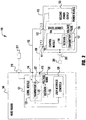
- FIG. 1 depicts an exemplary welding system 100 in accordance with an embodiment of the present invention.
- the welding system 100 can be any known type of welding system which employs a welding power supply and a wire feeder coupled to the power supply.
- the welding system can be a MIG type welding system.
- the embodiments discussed below will generally be described as a MIG welding system, but this is intended to be only exemplary, as embodiments of the preset invention can be employed in other types of welding systems, including for example GTAW, FCAW, SAW, stick, etc.
- MIG type welding systems are well known, the coupling of the system (e.g., wire feeder) to the welding torch and workpiece is not shown for clarity.
- the system can include a remote control and/or a pendant control device (which are generally known) which utilizes known communication methodologies.
- a remote control and/or a pendant control device which are generally known
- the exemplary embodiments described herein are described as welding systems, embodiments of the present invention can also be used in other systems, such as plasma cutting, etc., and as an extension, other components can be used, instead of a wire feeder and welding power supply as described herein. That is, the power supply can be a cutting power supply, power generator with a load, etc.
- the systems are described herein as welding for simplification and efficiency, but embodiments herein are not limited thereto.
- the communication circuitry, systems, methods and protocols described herein can be incorporated into these types of other systems by those of skill in the art.
- the system 100 contains a power supply 110 coupled to a wire feeder 140 via welding cables 150.
- the power supply 110 can be configured like known welding power supplies, with the additional features and attributes discussed herein.
- the power supply 110 can be configured like the Power Wave® welding systems manufactured by The Lincoln Electric Co. of Cleveland, Ohio.
- the wire feeder 140 can be configured like known wire feeders, with the additions discussed herein, an example of which is the PF-84 series wire feeders manufactured by The Lincoln Electric Company of Cleveland, Ohio.
- other power supplies and wire feeders can be used and these references are intended to be merely exemplary.
- the power supply 110 outputs a welding current, which is directed to the wire feeder 140, via the cables 150, so that the wire feeder can pass the current on to a welding electrode for welding a workpiece.
- the electrode is also the consumable, and in other processes, such as TIG, the electrode is not the consumable deposited into the weld.
- the cables 150 are the main welding power cables which deliver the welding power/current from the output studs 111/112 (see Fig. 2 ) of the power supply 110 to the wire feeder 140.
- the wire feeder 140 and the power supply 110 can communicate with each other both prior to, after and during welding. Often these communications are related to welding parameters, set points, feedback, etc.
- the welding systems use dedicated communication cables/lines between the power supply 110 and the wire feeder 140.
- the power supply 110 receives an AC signal as its input (not shown in FIG. 1 ).
- the AC signal can be received as a 3-phase input, or a single phase AC input signal.
- the AC signal can vary in voltage and frequency depending on the source of power and/or the country of operation.
- the AC input can be from a utility grid - which can range from 100 to 660 volts at 50 or 60Hz - or can be from a portable generator, which can also have a varying voltage and frequency.
- the system 100 is capable of operating properly and providing a welding or cutting signal regardless of the input AC voltage magnitude, phase type and frequency.
- the power supply 110 is designed to run in various modes including constant voltage (CV) and constant current (CC) modes, as suitable in various applications.
- the power supply 110 can include additional electrical components to condition the raw AC signal received and output the desired welding signal.
- the power from the power supply 110 is suitable for welding and is transmitted to the wire feeder 140 via the welding cables 150 - which are large diameter electrical conduits.
- the welding signal i.e., the current signal sent to the contact tip that is actually used for welding
- the wire feeder 140 passes on the received welding signal to the arc using cables.
- the power supply 110 is a multi-process type power supply 110 that is capable of outputting many different waveforms for welding and/or cutting.
- the power supply is capable of having its output current and voltage adjusted as desired and is capable of numerous types of processes including pulse welding, short arc welding, STT type welding, CC welding, CV welding, etc. Therefore, for a use there are numerous different types of welding options available and there are numerous output settings that can be used. As briefly discussed above, this availability of options and multitudes of settings can be a disadvantage and or can be undesirable as it can tend to lead to lack of control over a particular user.
- the power supply 110 has a key lock port 200 which receives a physical key 201 to unlock certain predetermined functionality on the power supply. This functionality will be described in more detail below.
- the wire feeder 140 can have a similar port 210 which receives a physical key 211 that unlocks certain functionality. It should be noted that in exemplary systems of the present invention the lock and key combination could be on either one of the power supply or wire feeder and need not be on both.
- the pendant can have a key lock port that receives a key to unlock functionality. It should be noted that while two keys 201 and 211 are shown in Figures 1 and 2 , and discussed below.
- Embodiments of the present invention can also use a single key that is capable of being used in either or both of the wire feeder and power supply. That is, in embodiments of the present invention, the below described functionality can be used with a single key which is compatible with either of a wire feeder and power supply in a welding system.
- the discussions herein of multiple keys are intended to be exemplary.
- the exemplary power supply 110 contains a welding power output module 103 which generates and outputs the welding power signal to the wire feeder.
- the welding output module can be constructed consistent with known systems, and can contain (for example), a rectifier, a buck, boost or buck- boost circuit to generate a regulated DC bus and an output circuit, such as a chopper, PWM, inverter, etc. which is used to generate the welding signal.
- This output module can be controlled consistent with known systems.
- the power supply 110 also contains a control module 101 which can be used to control the operation of the output module 103 and the power supply 110.
- the control module can contain a processor based computing system containing a memory, processor, etc. to control the operation of the power supply 110 consistent with known systems.
- the control module 101 contains a receiver 105 and a transmitter 107 to facilitate communication with the wire feeder 120 consistent with the embodiments discussed herein.
- the receiver 105 is coupled to at least one output line of the output module 103 with a current sense lead 104 to sense an output current of the output module 103.
- the control module 101 contains a transmitter 107 which is used facilitate the transmission of a data signal from the power supply to the wire feeder 140.
- the transmitter 107 is coupled to the output power module 103 via a voltage signal lead 106 - the use of which will be explained further below.
- the power source 110 also contains additional components and electronics, such as input controls, auxiliary power, etc. which are not shown for clarity.
- additional components and electronics such as input controls, auxiliary power, etc. which are not shown for clarity.
- the power supply can have a user interface to allow for the control or input of information for the power supply.
- the control module 101 can be configured and constructed similar to known control modules and include a processor, memory, etc. to facilitate and control the operation of the power supply. Such control modules are known and need not be described in detail herein.
- the key lock port 200 is coupled to the control module 101 such that the control module recognizes whether or not the key 201 is inserted in the port 200 and recognizes aspects of the key that unlocks certain functionalities or otherwise dictates operations of the power supply. That is, in some embodiments, not only is the coupling between the control module 101 and the port 200 one where the control module 101 recognizes the presence or absence of the key but also can have a communication link to allow for the exchange of information between the control module and the key. This will be discussed further below.
- the wire feeder 140 contains a controller module 121 which is used to facilitate communication with the power supply 110.
- the controller module 121 contains/is coupled to a user interface control board 126 which allows a user to input user/welding data to the wire feeder 140 to control operation of the system 100.
- the user interface 126 can be configured like any known user interface, and can include a data screen ( LED, etc.) user controls (knobs, buttons, etc.) and/or a touch sensitive input screen. Any known user interface configuration can be utilized.
- the user interface controls 126 need not be a part of the communication module, but the user input is at least coupled to the communication module to allow for the user input data to be communicated as discussed herein.
- the controller module 121 also includes a receiver 129 which is coupled to one of the wire feeder studs 113/114 which are coupled to one of the welding power lines 130 via a voltage sense lead 128. (although only one sense lead is shown, sense leads to each of the studs can be used to detect voltage at the studs). As explained further below, the voltage sense lead 128 is used to sense a voltage communication signal from the power supply 110.
- the controller module 121 also contains a communication module 123 having a transmitter 125 and a current sink circuit 127 which is used to vary the current draw in the wire feeder 140 to facilitate communication with the power supply 110. This is explained further below.
- the wire feeder 140 can have other systems and components, such as motors, motor controls, etc. which are known and need not be shown or described for clarity.
- the controller module 121 can also have a processor, memory, etc. consistent with known controller modules to ensure the proper operation of the wire feeder 140.
- the wire feeder 140 can have a key lock port 210 which is coupled to the communication module, which can include a controller, processor, memory and the like. That is, the communication module/controller 121 can be used to communicate control inputs to the power supply and control the operation of the system. Again, in exemplary embodiments the communication module/controller 121 is capable of recognizing the presence or absence of a key 211 and/or capable of communication and/or exchanging information with the key 211 via port 210.
- the wire feeder 140 can receive its control and operational power from the power supply 110 via the cables 150.
- This operational power can be in the form of output voltage from the power supply 110 having an OCV voltage of about 60 volts (for example), and a power of about 50 watts (for example).
- OCV optical chemical vapor deposition
- the wire feeder 140 When the wire feeder 140 is powered up, it can receive user inputs via the user interface controls 126. Communication between the power supply, wire feeder, pendant and/or user interface can be accomplished by any known methods, and exemplary embodiments are not limited by the means of communication. For example, any wired or wireless communication protocol or methodology can be used, including digital communication links.
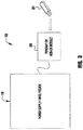
- Figure 3 depicts an embodiment of the system where the key 201 can engage with a pendant or add-on module 300 that is coupled to either the power supply or wire feeder.
- a pendant 300 some welding/cutting systems can be controlled by the use of a pendant 300.
- the key lock port can be located on the control pendant to receive the key 201 to allow for the control of the system as described later herein.
- the system 100 can use an add-on-module having a key lock port for the key 201, where the add-on module is coupled to a power supply/wire feeder that does not have a port to receive the key.
- this add-on module will allow the advantages of the present invention to be realized on older welding/cutting systems without the need for replacing or retrofitting the power supply/wire feeder. That is, the add-on-module is capable of being coupled to an existing power supply/wire feeder via either a USB or other type of communication port, or in some embodiments can be able to communicate wirelessly with existing/older power supplies.
- the add-on module 300 can then receive the key and communicate to the power supply/wire feeder that the key 201 is present or absent and communicate any other information from the key 201 as needed.
- Embodiments of the present invention are not limited by the construction of the add-on module or its method of communication with the power supply/wire feeder. However, in some embodiments the add-on module can be constructed similar to a pendant control module and be coupled to the power supply/wire feeder using a similar coupling mechanism and control methodology.
- Figures 4A through 4D depict exemplary embodiments of the physical key that can be used in embodiments of the present invention.
- the key 201 can have a USB type construction such that the key 201 can store/provide data to the welding/cutting system, which will be discussed further below.
- the key 201 has an electronic connection 460, such as a USB type connection (for example), and a housing 401.
- an electronic connection 460 such as a USB type connection (for example)
- a housing 401 a housing 401.
- embodiments of the present invention are not limited to using USB type data connections, but can use any other type of known data connection.
- the shape of the housing 401 is not limiting.
- the housing 401 can have a shape that interlocks or otherwise fits with the key lock port to firmly hold the key in place during operation and prevent inadvertent damage or removal.
- the housing of the key can have a particular shape that ensures the key is used with the appropriate power supply and/or is used to unlock or lock out operational features.
- the key housing 401 has at least one, or a plurality of, protrusion(s) 411/412 which can engage with the port on the power supply/wire feeder.
- embodiments of the present invention are not limited to the housing or key shapes described herein, which are intended to be exemplary.
- the shape of the key housing is used to ensure that the proper key is used for the proper power supply/wire feeder. That is, the shape of the key is used to prevent improper use/insertion.
- the shape of the key 201 (for example with the protrusions 411/412) is used to unlock or lock certain features.
- the key lock port on the power supply/wire feeder can have a micro-switch or micro-switches in the opening that engage with the projections 411/412 to control an operation of the system.
- a key lock port can be configured to receive any one of the four keys shown in Figures 4A through 4D .
- the controller of the power supply/wire feeder recognizes that none of the micro-switches are engaged and because of this limits the operation of the system to a first configuration. For example, this key configuration limits the system for only MIG welding, and no other operation can be used.
- the key shapes can be used to lock or unlock a type of operation
- the system can be programmed or controlled such that the shape of the key can unlock very specific parameters, or be programmed to unlock or enable only a single type of welding operation.
- a first key shape e.g., 4A
- the second key shape e.g., 4B
- the parameters are predetermined and locked.
- the second key shape can be used to unlock only MIG welding, where the MIG welding operation has a specific current waveform, voltage, current and/or frequency parameters.
- the control module of the power supply or controller of the system can be programmed, by a user, to use the different key shapes to lock or unlock different types of functions or operations, or can be programmed such that for any one key shape only a specific operation is made available.
- a supervisor can use the keys, given to respective welders, to control the welding/cutting processes being done.
- the key 201 need not have a USB or other electronic or data transfer connection. That is, in some embodiments the key can simply be structural keys that unlock certain features but do not otherwise have any communication or data capability. In this embodiments, different physical keys lock or unlock different operations.
- the keys can be plastic, metal or any other type of material. Further, the keys can have a magnetic portion (not shown) that aids in holding the key in place within the key lock port.
- embodiments of the present invention allows for one or more keys to be used to unlock certain weld schedules, weld types or weld parameters and/or allows for certain functions and processes to be locked out - to prevent from being used. Further, embodiments of the present invention allow for the customization of what features, parameters, operations can be locked or unlocked by a given key. This can be done via the user interface on the power supply and/or wire feeder or by another computer system that can be coupled to the power supply/wire feeder.
- the weld system can be programmed such that no operation of any kind can be commenced without the presence of a physical recognized key. That is, without the recognition of an inserted key, no user can operate the system. This can ensure that the system is being used by an authorized user in an authorized way.
- the key 201 can contain electronic information and/or storage.
- the key 201 can be configured similar to a USB type device.
- Such embodiments allow for increased flexibility of the control of any given operation. That is, the key can be programmed with any given weld operation parameters, limits, etc. which can be used by the power supply/wire feeder to control the weld operation. For example, for a given welding operation a supervisor can couple the key to a computer, welding system, etc. and download a set of weld parameters, weld type, etc. for a given welding operation.
- the computer can be any type of computer/control system to which the key can be coupled and which can transfer data onto the key to be used as described herein.
- the key can be programmed in any desirable and to control any desired parameters.
- the key in addition to being programmed to lock or unlock functions, or to set up the welding system for a given welding operation, including welding process parameters, the key can be programmed to only permit a set number of welding operations, or unlock the welding system for a given period of time. For example, a supervisor may determine that only 10 welding jobs with a given set of parameters should be done. As such, the key then only unlocks the welding system for 10 welding operations and use of the system will not be permitted after the 10 are completed.
- other possible control structures can be implemented and embodiments of the present invention are not limited in this way.
- each key can receive a store information from the welding/cutting system. That is, in addition to providing operation information to the system, the key can receive and store information from the system.
- the key can store operational information such as arc time, the number of welding events, start and stop times, the existence of any anomalies during a given welding operation etc.
- the key can be used to capture and store any desired information. This can be used for training purposes, and/or track the performance of a given welder during given welding operations. This can also be used to track productivity and/or performance of a given operator and/or can be used to track the productivity, efficiency and reliability of a given welding system, power supply and/or wire feeder.
- the key can be used to store information regarding the use and/or performance of any component of a welding system and be used to track and store information related to faults, errors and/or general maintenance and service.
- a welding system can be used to track and store information related to faults, errors and/or general maintenance and service.
- the system described herein, including the key can track the hours of operation and then provide the user/supervisor, etc. an indication regarding the remaining usable life to indicate to the user whether or not replaced meant necessary.
- the key can store an error signal or error event from a previous welding operation, and when the key is re-inserted into the same welding system the system controller can read from the key that an error had been previously recorded and then notify the user of the error and/or require that the error be cleared or addressed prior to a subsequent operation being authorized.
- the keys can be identified for a specific user. That is, in some embodiment each key is personalized to a given user. This ensures that, regardless of which system the key is plugged into, the user will be limited as desired and as programmed on the key. This can prevent users from being allowed to use different systems that they are not permitted to use, are not qualified for etc. Further, this can allow a supervisor to collect and track individual user performance.
- the key can be a "single use" or limited use key that tracks and stores information regarding a welding operation. For example, in some applications it may be desirable to track and store and welding data for a given project, either temporarily or permanently. This could be advantageous in very high importance welding projects.
- a key can be used for only 10 welding operations, which it unlocks. For each of the 10 welding operations the key stores information including operator identification information, date, weld start time, stop time, current and voltage peaks, heat input, the existence of any anomalies (e.g., significant shorting events), or any other parameters or combination of parameters that are desired to be maintained. Once the 10th welding operation is completed the key stores the last of the information and cannot be reused.
- the supervisor can then take the key and upload and/or review the stored information, which can be kept indefinitely.
- This data can be uploaded to any computer system, network, data storage facility or the like.
- the weld data can be reviewed for any potential issues that may require a further inspection and/or stored indefinitely until such time review of the data could be needed.
- the key can be configured to lock unlock for any number of operations, and need not be limited to 10 operations.
- the key can be programmed to be usable for a given amount of time or for a specific date. That is, a key can be used for one day (or a defined period of time) to unlock certain welding/cutting operations and after the expiration of the desired time frame the key does not unlock any further operations.
- the key can store whatever is needed or desired for the duration it is used.
- the keys can be re-usable but can only be re-used after the stored data is captured and stored. For example, at the end of a work day the supervisor can capture the data from the key onto some other computer system, and upon successful capture of the data, the supervisor can then reset the key to be usable again.
- the key is not needed to use or otherwise operate the welding/cutting system, but the key is needed to make changes or to unlock certain features as discussed above.
- a user could use the system without a key for any desired functionality so long as that functionality does not require the key to unlock it. However, if the user wishes to depart from the permitted parameters/weld types, etc. the user must insert the key to permit the desired change.
- embodiments of the present invention allow for the detailed control of welding and cutting operations, with the added security of a physical key.
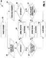
- FIG. 5 shows an exemplary flow chart 500 that can be used with embodiments of the invention consistent with the descriptions discussed above.
- the power supply or system does not require the initial insertion of a key before being turned on 510. Then the user either attempts to change a weld menu setting 520 or a weld parameter 530. Upon the attempted changes 520/530 the system checks to see if the key is present and enables or authorizes the requested inputs/changes 540/550. If the needed key is not present the system can either allow the permitted operations 545, and ignore the requested changes, or simply lock out any use and not permit any operation.
- the system determines if the requested change is within the authorized limits for the changes 560/570. If the key unlocks all functionality then all changes would be authorized. However, the key may only permit certain changes and so the system determines if the requested change is within the allowed scope. If the change is permitted, then the change is allowed 580. However, if the change is not permitted the change can be restricted to an allowed parameter change or, again, no operation could be permitted 565. As indicated previously, other steps and processes can be implemented without departing from the scope or spirit of the present invention. For example, data can be stored as described above.
- the user interface on anyone of the power supply, wire feeder and/or pendant can display the key status to a user.
- a status of key insertion can be displayed as well as the restrictions that are in place with or without the key.
- the user interface can display the process limits, parameters etc. and can indicate to a user when a desired operation or parameter is outside of the authorized scope.
- the attempt to use a welding/cutting system outside of permitted parameters or without a key can be reported to a central computer for review and/or authorization.
- a welding/cutting power supply can report to the central computer that an unauthorized change or use has been attempted. From the central station the supervisor could then authorize the change and/or stop any operation until the situation is made clear.
- Method steps can be performed by one or more programmable processors executing a computer program to perform functions of the invention by operating on input data and generating output. Method steps can also be performed by, and apparatus can be implemented as, special purpose logic circuitry, e.g., an FPGA (field programmable gate array) or an ASIC (application specific integrated circuit). Modules can refer to portions of the computer program and/or the processor/special circuitry that implements that functionality.
- FPGA field programmable gate array
- ASIC application specific integrated circuit
- processors suitable for the execution of a computer program include, by way of example, both general and special purpose microprocessors, and any one or more processors of any kind of digital computer.
- a processor will receive instructions and data from a read- only memory or a random access memory or both.
- the essential elements of a computer are a processor for executing instructions and one or more memory devices for storing instructions and data.
- a computer will also include, or be operatively coupled to receive data from or transfer data to, or both, one or more mass storage devices for storing data, (e.g., magnetic, magneto-optical disks, or optical disks). Data transmission and instructions can also occur over a communications network.
- Information carriers suitable for embodying computer program instructions and data include all forms of non-volatile memory, including by way of example semiconductor memory devices, e.g., EPROM, EEPROM, and flash memory devices; magnetic disks, e.g., internal hard disks or removable disks; magneto-optical disks; and CD-ROM and DVD-ROM disks.
- semiconductor memory devices e.g., EPROM, EEPROM, and flash memory devices
- magnetic disks e.g., internal hard disks or removable disks
- magneto-optical disks e.g., CD-ROM and DVD-ROM disks.
- the processor and the memory can be supplemented by, or incorporated in special purpose logic circuitry.
- the above described techniques can be implemented on a CNC or computer having a display device, e.g., a CRT (cathode ray tube) or LCD (liquid crystal display) monitor, for displaying information to the user and a keyboard and a pointing device, e.g., a mouse or a trackball, by which the user can provide input to the computer (e.g., interact with a user interface element).
- a display device e.g., a CRT (cathode ray tube) or LCD (liquid crystal display) monitor
- a keyboard and a pointing device e.g., a mouse or a trackball
- feedback provided to the user can be any form of sensory feedback, e.g., visual feedback, auditory feedback, or tactile feedback; and input from the user can be received in any form, including acoustic, speech, or tactile input.
- the above described techniques can be implemented in a distributed computing system that includes a back-end component, e.g., as a data server, and/or a middleware component, e.g., an application server, and/or a front-end component, e.g., a client computer having a graphical user interface and/or a Web browser through which a user can interact with an example implementation, or any combination of such back- end, middleware, or front-end components.
- the components of the system can be interconnected by any form or medium of digital data communication, e.g., a communication network. Examples of communication networks include a local area network ("LAN”) and a wide area network (“WAN”), e.g., the Internet, and include both wired and wireless networks.
- LAN local area network
- WAN wide area network
- Comprise, include, and/or plural forms of each are open ended and include the listed parts and can include additional parts that are not listed. And/or is open ended and includes one or more of the listed parts and combinations of the listed parts.
- REFERENCE NUMERALS 100 system 150 welding cable 101 control module 200 key port 103 welding power output module 201 key 104 current sense lead 210 port 105 receiver 211 key 106 woltage signal lead 300 pendant 107 transmitter 401 housing 110 power supply 411 protrusion 111 output stud 412 protrusion 112 output stud 460 electronic connection 113 wire feeder studs 500 flow chart 114 wire feeder studs 510 step 120 wire feeder 520 step 121 controller module 530 step 123 communication module 540 step 125 transmitter 545 step 126 user interface control board 550 step 127 current sink circuit 560 step 128 voltage sense lead 565 step 129 receiver 570 step 130 welding power lines 580 step 140 wire feeder
Landscapes
- Engineering & Computer Science (AREA)
- Physics & Mathematics (AREA)
- Plasma & Fusion (AREA)
- Mechanical Engineering (AREA)
- Theoretical Computer Science (AREA)
- Arc Welding Control (AREA)
Applications Claiming Priority (1)
| Application Number | Priority Date | Filing Date | Title |
|---|---|---|---|
| US15/949,673 US10821538B2 (en) | 2018-04-10 | 2018-04-10 | System and method of unlocking features and parameters in a welding or cutting system using a physical key |
Publications (1)
| Publication Number | Publication Date |
|---|---|
| EP3552747A1 true EP3552747A1 (fr) | 2019-10-16 |
Family
ID=66105066
Family Applications (1)
| Application Number | Title | Priority Date | Filing Date |
|---|---|---|---|
| EP19168433.1A Withdrawn EP3552747A1 (fr) | 2018-04-10 | 2019-04-10 | Système et procédé de déverrouillage de fonctionnalités et de paramètres dans un système de soudage ou de découpe à l'aide d'une clé physique |
Country Status (4)
| Country | Link |
|---|---|
| US (1) | US10821538B2 (fr) |
| EP (1) | EP3552747A1 (fr) |
| JP (1) | JP2019181569A (fr) |
| CN (1) | CN110355446A (fr) |
Families Citing this family (2)
| Publication number | Priority date | Publication date | Assignee | Title |
|---|---|---|---|---|
| US11664971B2 (en) * | 2019-11-13 | 2023-05-30 | The Esab Group Inc. | Encrypted communication between components of welding and cutting systems |
| CN121607776A (zh) * | 2026-02-02 | 2026-03-06 | 四川思创激光科技有限公司 | 激光焊机系统参数修改方法及装置 |
Citations (5)
| Publication number | Priority date | Publication date | Assignee | Title |
|---|---|---|---|---|
| US6600406B1 (en) * | 1997-05-23 | 2003-07-29 | Irevo, Inc. | Electronic information key system |
| US20050023261A1 (en) * | 2003-07-30 | 2005-02-03 | Bing Zheng | Adaptive and synergic fill welding method and apparatus |
| US20140061169A1 (en) * | 2012-08-29 | 2014-03-06 | Illinois Tool Works Inc. | User interface for welding equipment and systems |
| US20150283652A1 (en) * | 2014-04-07 | 2015-10-08 | Illinois Tool Works Inc. | System and method for determining inductance of a power cable |
| US20150375327A1 (en) * | 2014-06-27 | 2015-12-31 | Illinois Tool Works Inc. | System and method for remote welding training |
Family Cites Families (49)
| Publication number | Priority date | Publication date | Assignee | Title |
|---|---|---|---|---|
| US4937863A (en) | 1988-03-07 | 1990-06-26 | Digital Equipment Corporation | Software licensing management system |
| US4993627A (en) * | 1989-05-02 | 1991-02-19 | Phelan Michael D | Electronically controlled locking mechanism |
| US5923707A (en) | 1996-08-30 | 1999-07-13 | Canon Kabushiki Kaisha | Reproducing apparatus capable of generating clock signal synchronized in phase with reproduced data |
| WO1997010919A1 (fr) | 1995-09-19 | 1997-03-27 | Kabushiki Kaisha Yaskawa Denki | Dispositif de reglage automatique de conditions de soudage |
| US5667704A (en) | 1996-02-20 | 1997-09-16 | Robotron | Multiple sequence welding controller |
| US5905860A (en) | 1996-03-15 | 1999-05-18 | Novell, Inc. | Fault tolerant electronic licensing system |
| DE29617200U1 (de) | 1996-10-02 | 1997-11-06 | Siemens AG, 80333 München | Vorrichtung zur prädiktiven Diagnose der aktuellen Güte des technischen Arbeitsergebnisses einer technischen Anlage, insbesondere der aktuellen Güte der Schweißpunkte eines Punktschweißroboters |
| US5808885A (en) | 1996-12-20 | 1998-09-15 | Square D Company | Weld controller system for coupling to a common database system on a communication network |
| US5923756A (en) | 1997-02-12 | 1999-07-13 | Gte Laboratories Incorporated | Method for providing secure remote command execution over an insecure computer network |
| US5937414A (en) | 1997-02-28 | 1999-08-10 | Oracle Corporation | Method and apparatus for providing database system replication in a mixed propagation environment |
| US6091048A (en) | 1997-05-16 | 2000-07-18 | Illinois Tool Works Inc. | Welding machine with automatic parameter setting |
| US6051805A (en) | 1998-01-20 | 2000-04-18 | Air Liquide Canada | Methods and apparatus for welding performance measurement |
| AT409239B (de) | 1998-05-13 | 2002-06-25 | Fronius Schweissmasch | Verfahren zum steuern eines schweissgerätes und steuervorrichtung hierfür |
| US6415276B1 (en) | 1998-08-14 | 2002-07-02 | University Of New Mexico | Bayesian belief networks for industrial processes |
| AT409731B (de) | 1998-10-16 | 2002-10-25 | Fronius Schweissmasch Prod | Regelvorrichtung für ein schweissgerät |
| US6024273A (en) | 1998-12-04 | 2000-02-15 | Caterpillar Inc. | Method and system for determining weld bead quality |
| US20050080799A1 (en) | 1999-06-01 | 2005-04-14 | Abb Flexible Automaton, Inc. | Real-time information collection and distribution system for robots and electronically controlled machines |
| AT501741B1 (de) | 1999-08-16 | 2006-11-15 | Fronius Int Gmbh | Schweissgerät mit kommunikationsschnittstelle und verfahren zum betreiben des schweissgerätes |
| US20070043675A1 (en) | 2000-05-15 | 2007-02-22 | Siemens Aktiengesellschaft | Software license manager |
| US7278142B2 (en) | 2000-08-24 | 2007-10-02 | Veritas Operating Corporation | Dynamic computing environment using remotely allocable resources |
| US6479792B1 (en) | 2000-09-06 | 2002-11-12 | Illinois Tool Works Inc. | Welding machine, system and method therefor |
| EP1216783A1 (fr) | 2000-12-08 | 2002-06-26 | L'air Liquide, S.A. à Directoire et Conseil de Surveillance pour l'Etude et l'Exploitation des Procédés Georges Claude | Procédé et système pour résoudre un problème se posant lors d'une opération de soudage ou analogue |
| US7761336B1 (en) | 2001-04-20 | 2010-07-20 | Lincoln Global, Inc. | System and method for managing welding consumables |
| US8224881B1 (en) | 2001-06-18 | 2012-07-17 | Lincoln Global, Inc. | System and method for managing welding information |
| US20060012683A9 (en) | 2002-11-11 | 2006-01-19 | Ich-Kien Lao | Digital video system-intelligent information management system |
| JP2005222409A (ja) | 2004-02-06 | 2005-08-18 | Internatl Business Mach Corp <Ibm> | オペレーティングシステム、ライセンス管理サーバ、ライセンス管理方法、ライセンス管理プログラム、及び記録媒体 |
| US7412232B2 (en) | 2004-12-22 | 2008-08-12 | Research In Motion Limited | Method and system for controlling software loads on a third-party mobile station |
| US20070118699A1 (en) | 2005-11-23 | 2007-05-24 | General Electric Company | System and method for updating turbine controls and monitoring revision history of turbine fleet |
| US7844997B2 (en) * | 2006-01-12 | 2010-11-30 | Honeywell International Inc. | Securing standard test access port with an independent security key interface |
| US20070169256A1 (en) * | 2006-01-24 | 2007-07-26 | Salvador Arraz | Sink cabinet floor protector |
| US20070244823A1 (en) | 2006-04-13 | 2007-10-18 | Bowe Bell + Howell Company | Web-based method and system for enabling licensed products and features |
| US8525077B2 (en) * | 2006-05-09 | 2013-09-03 | Lincoln Global, Inc. | Touch screen waveform design apparatus for welders |
| JP4908961B2 (ja) | 2006-07-27 | 2012-04-04 | キヤノン株式会社 | 情報処理方法、情報処理装置、プログラム及び記憶媒体 |
| CN101055649A (zh) * | 2006-12-26 | 2007-10-17 | 奇瑞汽车有限公司 | 一种用于车载防盗安全装置 |
| US20080306786A1 (en) | 2007-06-05 | 2008-12-11 | Lonowski Wayne J | License management tool to monitor and analyze license usage to determine need for additional licenses |
| US8707421B2 (en) | 2007-06-29 | 2014-04-22 | Siemens Industry, Inc. | System and method for a web based teleservice for updating machine software |
| JP4958671B2 (ja) | 2007-07-24 | 2012-06-20 | キヤノン株式会社 | ライセンス管理装置、ライセンス管理方法、及びコンピュータプログラム |
| US20090222804A1 (en) | 2008-02-29 | 2009-09-03 | Illinois Tool Works, Inc. | Embedded firmware updating system and method |
| US9676050B2 (en) | 2009-11-17 | 2017-06-13 | Illinois Tool Works Inc. | Welding system with lockout mechanism |
| US8592723B2 (en) * | 2010-02-12 | 2013-11-26 | Illinois Tool Works Inc. | Weld bank data structures for welding applications |
| EP2550620B1 (fr) * | 2010-03-24 | 2014-07-02 | e-BO Enterprises | Système de distribution de contenu sécurisé |
| US20120022882A1 (en) | 2010-07-20 | 2012-01-26 | Lincoln Global, Inc. | Licensing features in welding equipment |
| US9862051B2 (en) | 2011-09-27 | 2018-01-09 | Illinois Tool Works Inc. | Welding system and method utilizing cloud computing and data storage |
| GB2496686A (en) * | 2011-11-21 | 2013-05-22 | Uniarc Ltd | Remote control apparatus for a welding machine |
| US10213861B2 (en) | 2013-03-11 | 2019-02-26 | Illinois Tool Works Inc. | Automated system for machine set-up of welding power sources and welding systems |
| US9446471B2 (en) | 2013-03-15 | 2016-09-20 | Lincoln Global, Inc. | Systems and methods for communicating with welding equipment |
| US10105782B2 (en) * | 2014-01-07 | 2018-10-23 | Illinois Tool Works Inc. | Feedback from a welding torch of a welding system |
| US10665128B2 (en) | 2014-06-27 | 2020-05-26 | Illinois Tool Works Inc. | System and method of monitoring welding information |
| US9862049B2 (en) | 2014-06-27 | 2018-01-09 | Illinois Tool Works Inc. | System and method of welding system operator identification |
-
2018
- 2018-04-10 US US15/949,673 patent/US10821538B2/en active Active
-
2019
- 2019-03-28 CN CN201910240736.9A patent/CN110355446A/zh active Pending
- 2019-04-05 JP JP2019072644A patent/JP2019181569A/ja active Pending
- 2019-04-10 EP EP19168433.1A patent/EP3552747A1/fr not_active Withdrawn
Patent Citations (5)
| Publication number | Priority date | Publication date | Assignee | Title |
|---|---|---|---|---|
| US6600406B1 (en) * | 1997-05-23 | 2003-07-29 | Irevo, Inc. | Electronic information key system |
| US20050023261A1 (en) * | 2003-07-30 | 2005-02-03 | Bing Zheng | Adaptive and synergic fill welding method and apparatus |
| US20140061169A1 (en) * | 2012-08-29 | 2014-03-06 | Illinois Tool Works Inc. | User interface for welding equipment and systems |
| US20150283652A1 (en) * | 2014-04-07 | 2015-10-08 | Illinois Tool Works Inc. | System and method for determining inductance of a power cable |
| US20150375327A1 (en) * | 2014-06-27 | 2015-12-31 | Illinois Tool Works Inc. | System and method for remote welding training |
Also Published As
| Publication number | Publication date |
|---|---|
| US10821538B2 (en) | 2020-11-03 |
| US20190308269A1 (en) | 2019-10-10 |
| CN110355446A (zh) | 2019-10-22 |
| JP2019181569A (ja) | 2019-10-24 |
Similar Documents
| Publication | Publication Date | Title |
|---|---|---|
| US11344962B2 (en) | Weld bank data structures for welding applications | |
| US20250018492A1 (en) | Automated system for machine set-up of welding power sources and welding systems | |
| US11453078B2 (en) | Use of mobile communication devices as user interface for welding equipment and systems | |
| US8445816B2 (en) | Modular process list for welding power supply | |
| US8525077B2 (en) | Touch screen waveform design apparatus for welders | |
| US10496080B2 (en) | Welding job sequencer | |
| CN106457443B (zh) | 用于发动机驱动式焊接电源的无线控制的系统和方法 | |
| US7772524B2 (en) | Integrating sensors over a digital link | |
| US6815640B1 (en) | Apparatus, system and method to facilitate reconfigurable welding power supply | |
| RU2593313C2 (ru) | Система и способ сварки с управлением электрической дугой, основанным на цифровой связи | |
| CN105392589A (zh) | 用于与焊接装备通信的系统和方法 | |
| CN105073323A (zh) | 具有焊接程序记忆的电压传感送丝器 | |
| EP3552747A1 (fr) | Système et procédé de déverrouillage de fonctionnalités et de paramètres dans un système de soudage ou de découpe à l'aide d'une clé physique | |
| JPH0538586A (ja) | 抵抗溶接システム | |
| US12605786B2 (en) | Systems and methods to configure a robotic welding system | |
| US20220063010A1 (en) | Welding-type power supplies with job specific weld monitoring systems | |
| JP2007210007A (ja) | 溶接電源のロック制御方法。 | |
| EP4157576A1 (fr) | Dispositif d'acquisition de paramètres de soudage | |
| AU2017201913A1 (en) | Automated system for machine set-up of welding power sources and welding systems |
Legal Events
| Date | Code | Title | Description |
|---|---|---|---|
| PUAI | Public reference made under article 153(3) epc to a published international application that has entered the european phase |
Free format text: ORIGINAL CODE: 0009012 |
|
| STAA | Information on the status of an ep patent application or granted ep patent |
Free format text: STATUS: THE APPLICATION HAS BEEN PUBLISHED |
|
| AK | Designated contracting states |
Kind code of ref document: A1 Designated state(s): AL AT BE BG CH CY CZ DE DK EE ES FI FR GB GR HR HU IE IS IT LI LT LU LV MC MK MT NL NO PL PT RO RS SE SI SK SM TR |
|
| AX | Request for extension of the european patent |
Extension state: BA ME |
|
| STAA | Information on the status of an ep patent application or granted ep patent |
Free format text: STATUS: REQUEST FOR EXAMINATION WAS MADE |
|
| 17P | Request for examination filed |
Effective date: 20200416 |
|
| RBV | Designated contracting states (corrected) |
Designated state(s): AL AT BE BG CH CY CZ DE DK EE ES FI FR GB GR HR HU IE IS IT LI LT LU LV MC MK MT NL NO PL PT RO RS SE SI SK SM TR |
|
| STAA | Information on the status of an ep patent application or granted ep patent |
Free format text: STATUS: EXAMINATION IS IN PROGRESS |
|
| 17Q | First examination report despatched |
Effective date: 20201029 |
|
| GRAP | Despatch of communication of intention to grant a patent |
Free format text: ORIGINAL CODE: EPIDOSNIGR1 |
|
| STAA | Information on the status of an ep patent application or granted ep patent |
Free format text: STATUS: GRANT OF PATENT IS INTENDED |
|
| INTG | Intention to grant announced |
Effective date: 20211021 |
|
| STAA | Information on the status of an ep patent application or granted ep patent |
Free format text: STATUS: THE APPLICATION IS DEEMED TO BE WITHDRAWN |
|
| 18D | Application deemed to be withdrawn |
Effective date: 20220301 |