EP3552644B1 - Tête distributrice pour l'application nasale de liquide provenant d'un accumulateur de pression - Google Patents
Tête distributrice pour l'application nasale de liquide provenant d'un accumulateur de pression Download PDFInfo
- Publication number
- EP3552644B1 EP3552644B1 EP18209877.2A EP18209877A EP3552644B1 EP 3552644 B1 EP3552644 B1 EP 3552644B1 EP 18209877 A EP18209877 A EP 18209877A EP 3552644 B1 EP3552644 B1 EP 3552644B1
- Authority
- EP
- European Patent Office
- Prior art keywords
- component
- discharge head
- inflow
- outer component
- inner component
- Prior art date
- Legal status (The legal status is an assumption and is not a legal conclusion. Google has not performed a legal analysis and makes no representation as to the accuracy of the status listed.)
- Active
Links
- 239000012530 fluid Substances 0.000 title description 14
- 239000007788 liquid Substances 0.000 claims description 68
- 238000007789 sealing Methods 0.000 claims description 7
- 230000008878 coupling Effects 0.000 claims description 6
- 238000010168 coupling process Methods 0.000 claims description 6
- 238000005859 coupling reaction Methods 0.000 claims description 6
- 238000011144 upstream manufacturing Methods 0.000 claims description 6
- 230000006835 compression Effects 0.000 claims description 4
- 238000007906 compression Methods 0.000 claims description 4
- 230000005489 elastic deformation Effects 0.000 claims description 4
- 238000007493 shaping process Methods 0.000 claims 3
- 238000007599 discharging Methods 0.000 claims 1
- 239000007921 spray Substances 0.000 description 13
- 239000000463 material Substances 0.000 description 7
- 230000015572 biosynthetic process Effects 0.000 description 5
- 230000000694 effects Effects 0.000 description 5
- 238000010276 construction Methods 0.000 description 4
- 238000004519 manufacturing process Methods 0.000 description 4
- 238000003825 pressing Methods 0.000 description 4
- 230000006978 adaptation Effects 0.000 description 2
- 230000008859 change Effects 0.000 description 2
- 238000006073 displacement reaction Methods 0.000 description 2
- 230000009471 action Effects 0.000 description 1
- 230000001580 bacterial effect Effects 0.000 description 1
- 244000052616 bacterial pathogen Species 0.000 description 1
- 239000011248 coating agent Substances 0.000 description 1
- 238000000576 coating method Methods 0.000 description 1
- 239000003086 colorant Substances 0.000 description 1
- 239000002131 composite material Substances 0.000 description 1
- 238000009826 distribution Methods 0.000 description 1
- 239000003814 drug Substances 0.000 description 1
- 229940079593 drug Drugs 0.000 description 1
- 230000006872 improvement Effects 0.000 description 1
- 238000001746 injection moulding Methods 0.000 description 1
- 238000003780 insertion Methods 0.000 description 1
- 230000037431 insertion Effects 0.000 description 1
- 238000000034 method Methods 0.000 description 1
- 230000004048 modification Effects 0.000 description 1
- 238000012986 modification Methods 0.000 description 1
- 230000008569 process Effects 0.000 description 1
- 239000003380 propellant Substances 0.000 description 1
- 230000000717 retained effect Effects 0.000 description 1
- 239000000243 solution Substances 0.000 description 1
- 230000007704 transition Effects 0.000 description 1
Images


Classifications
-
- B—PERFORMING OPERATIONS; TRANSPORTING
- B65—CONVEYING; PACKING; STORING; HANDLING THIN OR FILAMENTARY MATERIAL
- B65D—CONTAINERS FOR STORAGE OR TRANSPORT OF ARTICLES OR MATERIALS, e.g. BAGS, BARRELS, BOTTLES, BOXES, CANS, CARTONS, CRATES, DRUMS, JARS, TANKS, HOPPERS, FORWARDING CONTAINERS; ACCESSORIES, CLOSURES, OR FITTINGS THEREFOR; PACKAGING ELEMENTS; PACKAGES
- B65D83/00—Containers or packages with special means for dispensing contents
- B65D83/14—Containers or packages with special means for dispensing contents for delivery of liquid or semi-liquid contents by internal gaseous pressure, i.e. aerosol containers comprising propellant for a product delivered by a propellant
- B65D83/28—Nozzles, nozzle fittings or accessories specially adapted therefor
-
- A—HUMAN NECESSITIES
- A61—MEDICAL OR VETERINARY SCIENCE; HYGIENE
- A61M—DEVICES FOR INTRODUCING MEDIA INTO, OR ONTO, THE BODY; DEVICES FOR TRANSDUCING BODY MEDIA OR FOR TAKING MEDIA FROM THE BODY; DEVICES FOR PRODUCING OR ENDING SLEEP OR STUPOR
- A61M5/00—Devices for bringing media into the body in a subcutaneous, intra-vascular or intramuscular way; Accessories therefor, e.g. filling or cleaning devices, arm-rests
- A61M5/14—Infusion devices, e.g. infusing by gravity; Blood infusion; Accessories therefor
- A61M5/142—Pressure infusion, e.g. using pumps
- A61M5/145—Pressure infusion, e.g. using pumps using pressurised reservoirs, e.g. pressurised by means of pistons
-
- A—HUMAN NECESSITIES
- A61—MEDICAL OR VETERINARY SCIENCE; HYGIENE
- A61M—DEVICES FOR INTRODUCING MEDIA INTO, OR ONTO, THE BODY; DEVICES FOR TRANSDUCING BODY MEDIA OR FOR TAKING MEDIA FROM THE BODY; DEVICES FOR PRODUCING OR ENDING SLEEP OR STUPOR
- A61M11/00—Sprayers or atomisers specially adapted for therapeutic purposes
- A61M11/006—Sprayers or atomisers specially adapted for therapeutic purposes operated by applying mechanical pressure to the liquid to be sprayed or atomised
- A61M11/007—Syringe-type or piston-type sprayers or atomisers
-
- A—HUMAN NECESSITIES
- A61—MEDICAL OR VETERINARY SCIENCE; HYGIENE
- A61M—DEVICES FOR INTRODUCING MEDIA INTO, OR ONTO, THE BODY; DEVICES FOR TRANSDUCING BODY MEDIA OR FOR TAKING MEDIA FROM THE BODY; DEVICES FOR PRODUCING OR ENDING SLEEP OR STUPOR
- A61M15/00—Inhalators
- A61M15/009—Inhalators using medicine packages with incorporated spraying means, e.g. aerosol cans
-
- A—HUMAN NECESSITIES
- A61—MEDICAL OR VETERINARY SCIENCE; HYGIENE
- A61M—DEVICES FOR INTRODUCING MEDIA INTO, OR ONTO, THE BODY; DEVICES FOR TRANSDUCING BODY MEDIA OR FOR TAKING MEDIA FROM THE BODY; DEVICES FOR PRODUCING OR ENDING SLEEP OR STUPOR
- A61M15/00—Inhalators
- A61M15/08—Inhaling devices inserted into the nose
-
- B—PERFORMING OPERATIONS; TRANSPORTING
- B05—SPRAYING OR ATOMISING IN GENERAL; APPLYING FLUENT MATERIALS TO SURFACES, IN GENERAL
- B05B—SPRAYING APPARATUS; ATOMISING APPARATUS; NOZZLES
- B05B1/00—Nozzles, spray heads or other outlets, with or without auxiliary devices such as valves, heating means
- B05B1/12—Nozzles, spray heads or other outlets, with or without auxiliary devices such as valves, heating means capable of producing different kinds of discharge, e.g. either jet or spray
-
- B—PERFORMING OPERATIONS; TRANSPORTING
- B05—SPRAYING OR ATOMISING IN GENERAL; APPLYING FLUENT MATERIALS TO SURFACES, IN GENERAL
- B05B—SPRAYING APPARATUS; ATOMISING APPARATUS; NOZZLES
- B05B1/00—Nozzles, spray heads or other outlets, with or without auxiliary devices such as valves, heating means
- B05B1/34—Nozzles, spray heads or other outlets, with or without auxiliary devices such as valves, heating means designed to influence the nature of flow of the liquid or other fluent material, e.g. to produce swirl
- B05B1/3405—Nozzles, spray heads or other outlets, with or without auxiliary devices such as valves, heating means designed to influence the nature of flow of the liquid or other fluent material, e.g. to produce swirl to produce swirl
- B05B1/341—Nozzles, spray heads or other outlets, with or without auxiliary devices such as valves, heating means designed to influence the nature of flow of the liquid or other fluent material, e.g. to produce swirl to produce swirl before discharging the liquid or other fluent material, e.g. in a swirl chamber upstream the spray outlet
- B05B1/3421—Nozzles, spray heads or other outlets, with or without auxiliary devices such as valves, heating means designed to influence the nature of flow of the liquid or other fluent material, e.g. to produce swirl to produce swirl before discharging the liquid or other fluent material, e.g. in a swirl chamber upstream the spray outlet with channels emerging substantially tangentially in the swirl chamber
- B05B1/3431—Nozzles, spray heads or other outlets, with or without auxiliary devices such as valves, heating means designed to influence the nature of flow of the liquid or other fluent material, e.g. to produce swirl to produce swirl before discharging the liquid or other fluent material, e.g. in a swirl chamber upstream the spray outlet with channels emerging substantially tangentially in the swirl chamber the channels being formed at the interface of cooperating elements, e.g. by means of grooves
- B05B1/3436—Nozzles, spray heads or other outlets, with or without auxiliary devices such as valves, heating means designed to influence the nature of flow of the liquid or other fluent material, e.g. to produce swirl to produce swirl before discharging the liquid or other fluent material, e.g. in a swirl chamber upstream the spray outlet with channels emerging substantially tangentially in the swirl chamber the channels being formed at the interface of cooperating elements, e.g. by means of grooves the interface being a plane perpendicular to the outlet axis
-
- B—PERFORMING OPERATIONS; TRANSPORTING
- B05—SPRAYING OR ATOMISING IN GENERAL; APPLYING FLUENT MATERIALS TO SURFACES, IN GENERAL
- B05B—SPRAYING APPARATUS; ATOMISING APPARATUS; NOZZLES
- B05B1/00—Nozzles, spray heads or other outlets, with or without auxiliary devices such as valves, heating means
- B05B1/34—Nozzles, spray heads or other outlets, with or without auxiliary devices such as valves, heating means designed to influence the nature of flow of the liquid or other fluent material, e.g. to produce swirl
- B05B1/3405—Nozzles, spray heads or other outlets, with or without auxiliary devices such as valves, heating means designed to influence the nature of flow of the liquid or other fluent material, e.g. to produce swirl to produce swirl
- B05B1/341—Nozzles, spray heads or other outlets, with or without auxiliary devices such as valves, heating means designed to influence the nature of flow of the liquid or other fluent material, e.g. to produce swirl to produce swirl before discharging the liquid or other fluent material, e.g. in a swirl chamber upstream the spray outlet
- B05B1/3421—Nozzles, spray heads or other outlets, with or without auxiliary devices such as valves, heating means designed to influence the nature of flow of the liquid or other fluent material, e.g. to produce swirl to produce swirl before discharging the liquid or other fluent material, e.g. in a swirl chamber upstream the spray outlet with channels emerging substantially tangentially in the swirl chamber
- B05B1/3431—Nozzles, spray heads or other outlets, with or without auxiliary devices such as valves, heating means designed to influence the nature of flow of the liquid or other fluent material, e.g. to produce swirl to produce swirl before discharging the liquid or other fluent material, e.g. in a swirl chamber upstream the spray outlet with channels emerging substantially tangentially in the swirl chamber the channels being formed at the interface of cooperating elements, e.g. by means of grooves
- B05B1/3452—Nozzles, spray heads or other outlets, with or without auxiliary devices such as valves, heating means designed to influence the nature of flow of the liquid or other fluent material, e.g. to produce swirl to produce swirl before discharging the liquid or other fluent material, e.g. in a swirl chamber upstream the spray outlet with channels emerging substantially tangentially in the swirl chamber the channels being formed at the interface of cooperating elements, e.g. by means of grooves the cooperating elements being movable, e.g. adjustable relative to one another
-
- B—PERFORMING OPERATIONS; TRANSPORTING
- B65—CONVEYING; PACKING; STORING; HANDLING THIN OR FILAMENTARY MATERIAL
- B65D—CONTAINERS FOR STORAGE OR TRANSPORT OF ARTICLES OR MATERIALS, e.g. BAGS, BARRELS, BOTTLES, BOXES, CANS, CARTONS, CRATES, DRUMS, JARS, TANKS, HOPPERS, FORWARDING CONTAINERS; ACCESSORIES, CLOSURES, OR FITTINGS THEREFOR; PACKAGING ELEMENTS; PACKAGES
- B65D83/00—Containers or packages with special means for dispensing contents
- B65D83/14—Containers or packages with special means for dispensing contents for delivery of liquid or semi-liquid contents by internal gaseous pressure, i.e. aerosol containers comprising propellant for a product delivered by a propellant
- B65D83/16—Containers or packages with special means for dispensing contents for delivery of liquid or semi-liquid contents by internal gaseous pressure, i.e. aerosol containers comprising propellant for a product delivered by a propellant characterised by the actuating means
- B65D83/20—Containers or packages with special means for dispensing contents for delivery of liquid or semi-liquid contents by internal gaseous pressure, i.e. aerosol containers comprising propellant for a product delivered by a propellant characterised by the actuating means operated by manual action, e.g. button-type actuator or actuator caps
- B65D83/205—Actuator caps, or peripheral actuator skirts, attachable to the aerosol container
- B65D83/206—Actuator caps, or peripheral actuator skirts, attachable to the aerosol container comprising a cantilevered actuator element, e.g. a lever pivoting about a living hinge
-
- B—PERFORMING OPERATIONS; TRANSPORTING
- B65—CONVEYING; PACKING; STORING; HANDLING THIN OR FILAMENTARY MATERIAL
- B65D—CONTAINERS FOR STORAGE OR TRANSPORT OF ARTICLES OR MATERIALS, e.g. BAGS, BARRELS, BOTTLES, BOXES, CANS, CARTONS, CRATES, DRUMS, JARS, TANKS, HOPPERS, FORWARDING CONTAINERS; ACCESSORIES, CLOSURES, OR FITTINGS THEREFOR; PACKAGING ELEMENTS; PACKAGES
- B65D83/00—Containers or packages with special means for dispensing contents
- B65D83/14—Containers or packages with special means for dispensing contents for delivery of liquid or semi-liquid contents by internal gaseous pressure, i.e. aerosol containers comprising propellant for a product delivered by a propellant
- B65D83/16—Containers or packages with special means for dispensing contents for delivery of liquid or semi-liquid contents by internal gaseous pressure, i.e. aerosol containers comprising propellant for a product delivered by a propellant characterised by the actuating means
- B65D83/22—Containers or packages with special means for dispensing contents for delivery of liquid or semi-liquid contents by internal gaseous pressure, i.e. aerosol containers comprising propellant for a product delivered by a propellant characterised by the actuating means with a mechanical means to disable actuation
- B65D83/224—Tamper indicating means obstructing initial actuation, e.g. removable
- B65D83/226—Tamper indicating means obstructing initial actuation, e.g. removable preventing initial depression of the actuator
-
- B—PERFORMING OPERATIONS; TRANSPORTING
- B65—CONVEYING; PACKING; STORING; HANDLING THIN OR FILAMENTARY MATERIAL
- B65D—CONTAINERS FOR STORAGE OR TRANSPORT OF ARTICLES OR MATERIALS, e.g. BAGS, BARRELS, BOTTLES, BOXES, CANS, CARTONS, CRATES, DRUMS, JARS, TANKS, HOPPERS, FORWARDING CONTAINERS; ACCESSORIES, CLOSURES, OR FITTINGS THEREFOR; PACKAGING ELEMENTS; PACKAGES
- B65D83/00—Containers or packages with special means for dispensing contents
- B65D83/14—Containers or packages with special means for dispensing contents for delivery of liquid or semi-liquid contents by internal gaseous pressure, i.e. aerosol containers comprising propellant for a product delivered by a propellant
- B65D83/16—Containers or packages with special means for dispensing contents for delivery of liquid or semi-liquid contents by internal gaseous pressure, i.e. aerosol containers comprising propellant for a product delivered by a propellant characterised by the actuating means
- B65D83/22—Containers or packages with special means for dispensing contents for delivery of liquid or semi-liquid contents by internal gaseous pressure, i.e. aerosol containers comprising propellant for a product delivered by a propellant characterised by the actuating means with a mechanical means to disable actuation
- B65D83/224—Tamper indicating means obstructing initial actuation, e.g. removable
- B65D83/228—Tamper indicating means obstructing initial actuation, e.g. removable consisting of a rupturable connection between actuator element and actuator cap or skirt, e.g. tear strips or bridges
-
- B—PERFORMING OPERATIONS; TRANSPORTING
- B65—CONVEYING; PACKING; STORING; HANDLING THIN OR FILAMENTARY MATERIAL
- B65D—CONTAINERS FOR STORAGE OR TRANSPORT OF ARTICLES OR MATERIALS, e.g. BAGS, BARRELS, BOTTLES, BOXES, CANS, CARTONS, CRATES, DRUMS, JARS, TANKS, HOPPERS, FORWARDING CONTAINERS; ACCESSORIES, CLOSURES, OR FITTINGS THEREFOR; PACKAGING ELEMENTS; PACKAGES
- B65D83/00—Containers or packages with special means for dispensing contents
- B65D83/14—Containers or packages with special means for dispensing contents for delivery of liquid or semi-liquid contents by internal gaseous pressure, i.e. aerosol containers comprising propellant for a product delivered by a propellant
- B65D83/38—Details of the container body
-
- B—PERFORMING OPERATIONS; TRANSPORTING
- B65—CONVEYING; PACKING; STORING; HANDLING THIN OR FILAMENTARY MATERIAL
- B65D—CONTAINERS FOR STORAGE OR TRANSPORT OF ARTICLES OR MATERIALS, e.g. BAGS, BARRELS, BOTTLES, BOXES, CANS, CARTONS, CRATES, DRUMS, JARS, TANKS, HOPPERS, FORWARDING CONTAINERS; ACCESSORIES, CLOSURES, OR FITTINGS THEREFOR; PACKAGING ELEMENTS; PACKAGES
- B65D83/00—Containers or packages with special means for dispensing contents
- B65D83/14—Containers or packages with special means for dispensing contents for delivery of liquid or semi-liquid contents by internal gaseous pressure, i.e. aerosol containers comprising propellant for a product delivered by a propellant
- B65D83/44—Valves specially adapted therefor; Regulating devices
Definitions
- the invention relates to a discharge head for the application of pharmaceutical liquids, in particular for the nasal application of pharmaceutical liquids from a pressure accumulator, which has an outlet valve with a valve connector which can be acted upon by force against a spring force to open the outlet valve.
- the invention also relates to a dispenser with such a discharge head.
- Similar discharge heads and dispensers are for example from the DE 102012200545 A1 known.
- the discharge heads disclosed in this document have an outer housing which, on the one hand, contains the basis for connection to a pressure accumulator and, on the other hand, forms the outer shell of a nasal applicator together with the discharge opening.
- An inner component is inserted into the elongated nasal applicator, which, together with the outer shell, serves to convey fluid to the discharge opening.
- the above-mentioned discharge heads are used for the distribution of drugs with a comparatively low retail price. It is therefore necessary that the discharge heads can be manufactured inexpensively.
- the one-piece design of the outer housing with base and nasal applicator which is advantageous in this regard, is well suited for achieving low costs.
- the supply of the liquid plastic in the context of the injection molding process usually takes place in the area of the base.
- the discharge opening is therefore comparatively far away from the feed point, which sometimes leads to an unsatisfactory manufacturing accuracy at the discharge opening and on fluid guide surfaces upstream of the discharge opening. This is disadvantageous because it means that the discharge behavior of the liquid can vary from dispenser to dispenser and no longer corresponds to the intended discharge behavior.
- the object of the invention is therefore to develop a generic dispenser in such a way that a high level of production accuracy is achieved in the area of the discharge opening without significantly increasing the complexity of production.
- the invention according to claim 1 relates to a discharge head for the nasal application of pharmaceutical liquids from a pressure accumulator, which has an outlet valve with a valve connector which can be acted upon by force against a spring force to open the outlet valve.
- a discharge head has an applicator in the form of a nasal applicator, at the end of which a discharge opening is provided which is connected through an applicator channel of the nasal applicator to an inlet of the applicator and thus indirectly to the liquid reservoir.
- the discharge opening in the sense of the invention is to be understood as the end of the applicator channel, i.e. the transition point at which the pressurized liquid is released into an external environment under ambient pressure and there, depending on the type of exit through the discharge opening, is present as a free jet or as a spray jet.
- the discharge opening preferably has a minimum cross-sectional area of less than 4 mm 2 , in particular less than 2 mm 2 .
- the applicator according to the invention also has an inner component and an outer component.
- the outer component is provided as a component that is separate from the inner component and is attached directly or indirectly to the inner component in a manner by which it can be moved in a purely rotational manner relative to the inner component.
- This purely rotative mobility can be brought about by a corresponding axially locking coupling of the inner part and the outer part.
- the inner component is basically axially movable with respect to the outer component, but is held on it in a frictional manner and no relative force can be applied by the user from the outside, by means of which the inner component and the outer component are axially displaced relative to one another. This is explained in more detail below.
- the design of the rotatable outer component as a component separate from a base of the discharge head is advantageous, since this makes it possible to achieve an exchangeability of the outer component, which is advantageous for reasons of hygiene.
- the discharge opening where liquid can remain after use, can quickly become contaminated with germs.
- By replacing the outer component all or at least particularly endangered areas are replaced.
- an adult-friendly or child-friendly design can be achieved by choosing the right external component be achieved. It is possible that a target group-specific adaptation is already carried out by the manufacturer and that several external components are supplied to the end customer so that he can carry out the adaptation himself once or on a case-by-case basis.
- the applicator is designed as a nasal applicator, it is inserted into a nostril of the user as intended.
- it is an elongated, slender applicator, which preferably has a shape that tapers towards the distal end and the discharge opening.
- the nasal applicator preferably protrudes at least 20 mm from the level of an actuating surface. Its length protruding freely from the base or the actuating surface is preferably at least a factor of 2, in particular preferably at least a factor of 2.5, greater than the maximum diameter of the nasal applicator.
- the discharge head preferably has a base and a coupling device provided thereon, by means of which the discharge head can be fastened to the pressure accumulator. It also preferably has a displaceable actuating surface which can be displaced with respect to said base and on which a tappet designed as a hollow tube is provided, which can be displaced together with the actuating surface for the purpose of applying force to the valve connector of the pressure accumulator.
- the actuating surface is preferably provided with a structure, for example a corrugation. Said applicator extends outward from the actuating surface.
- the basis of a discharge head according to the invention is that part which is properly coupled to the pressure accumulator.
- the coupling device is provided, which, in particular, is preferably snapped onto the pressure accumulator via molded locking edges.
- the base preferably has a ring-like structure with inwardly pointing latching lugs.
- a crimp connection is provided between a cover and a jacket, which is preferably used to snap on the latching lugs.
- the applicator in particular in the form of a nasal applicator, has an inner component which is preferably integrally connected to the actuating surface and / or the base or is attached to a guide component in an axially displaceable and rotationally fixed manner, which in turn is integral to the actuating surface and / or the Base is connected. Furthermore, it has an outer component, which is designed as a component that is separate from the inner component and the inner component is attached to it in a surrounding manner.
- the discharge opening is an opening in the outer component intended.
- An applicator channel leading to the discharge opening is delimited jointly by the outer component and the inner component.
- the outer component and the actuating surface of the discharge head preferably have different colors and / or different materials.
- the two-tone nature of the base and outer component can be used in particular for the purpose of aesthetic improvement, but also to adapt the discharge head to a company-specific, typical color scheme.
- the use of different materials also makes it possible to choose ideally matched materials for the outer component and the base including the operating handle.
- the outer component could be made of a material that prevents bacterial growth through coating or inherent material properties or which is perceived as pleasant to the touch in contact with the user's skin, while the main component with base and operating handle can be made of a different material.
- the actuating surface is preferably attached to the base in a pivotable manner, in particular preferably by means of a plastic bridge which integrally connects the base and the actuating surface and which acts as a swivel joint. It is also particularly advantageous if, in the delivery state, a securing bridge is provided on a side of the actuating surface opposite the plastic bridge, which connects the actuating surface and the base in one piece and breaks as intended upon initial actuation.
- the aforementioned one-piece design with a deformable plastic bridge as a joint is advantageous in terms of a construction from a few individual parts.
- the actuating surface is cut free by a slot away from the plastic bridge opposite the base, so that it can be moved.
- the safety bridge ensures that there is no unwanted discharge of liquid before commissioning, since the commissioning for the purpose of breaking this safety bridge requires a stronger application of force.
- An axis defined by the discharge direction of the discharge opening and / or by an axis of rotation of the outer component with respect to the inner component preferably encloses an angle between 5 ° and 85 °, preferably an angle between 10 ° and 50 °, with a placement direction of the discharge head on a pressure accumulator.
- This angling is common in discharge heads of the generic type. It allows an advantageous use in which the pressure accumulator, the main direction of extent of which preferably coincides with the placement direction, can be held slightly angled and the nasal applicator can then be pushed into a nostril at a suitable angle.
- the actuation surface and the nasal applicator are arranged next to one another, so that an asymmetrical shape of the discharge head is given.
- the discharge opening of a discharge head according to the invention is provided as an opening in the outer component and is surrounded on the inside by an end inner surface. Opposite the front-side inner surface, an end-face of the inner component is provided, which lies flat against the front-side inner surface.
- At least two inflow channels are formed in the form of inflow grooves on the front inner surface of the outer component and / or on the front surface of the inner component, which are connected or separated from the inflow area upstream of the inflow grooves and thus the liquid reservoir, depending on a rotational position of the outer component relative to the inner component.
- the aforementioned inflow grooves thus connect the inflow area, into which liquid initially flows from the liquid reservoir, with the discharge opening.
- At least two inflow grooves with different designs make it possible to influence the discharge characteristics of the liquid discharged through the discharge opening. If a first of the inflow grooves is flowed through in a first rotational position while the second inflow groove is closed, the first inflow groove and its shape, orientation and throttling effect determine the discharge characteristics. If, for example, a radially aligned inflow groove is involved, this does not lead to turbulence and the liquid is discharged as a so-called jet. If the second inflow groove is opened instead of the first in a second rotational position deviating therefrom, its shape, orientation and throttling effect determine the discharge characteristics.
- the liquid can be given a swirl which, when discharged through the discharge opening, favors the formation of a spray jet.
- the opening and / or closing of the inflow grooves brought about by rotating the outer component can also be used solely to discharge different amounts of liquid, that is to say to achieve an adjustable throttling effect.
- two different types of inflow grooves are provided, namely at least one essentially radially aligned radial groove and at least one tangential groove angled relative to the discharge opening, the central direction of which is not aligned with the discharge opening is provided.
- the radial groove or the radial grooves serve to generate the aforementioned jet, while the tangential groove or tangential grooves serve to form a vortex and thus a spray jet.
- several of the radial grooves and / or the tangential grooves are provided, preferably at least three each, which are particularly preferably evenly distributed over the circumference in order to bring about a uniform and essentially rotationally symmetrical discharge.
- the at least two inflow grooves are both provided in the area of the front inner surface of the outer component and the end surface of the inner component, whereby they are preferably arranged separately in such a way that no liquid unintentionally flows into the inflow groove each other inflow groove and along which can flow to the discharge opening.
- a design is advantageous in which at least one inflow groove is provided in the end-face inner surface of the outer component and at least one inflow groove is provided in the end face of the inner component. Both surfaces pressed against one another, the front-side inner surface of the outer component and the front-side of the inner component, are therefore used to arrange the inflow grooves. This enables them to be reliably isolated from one another even with a small overall size.
- the arrangement of the inflow grooves on the front inner surface and the end surface is advantageous.
- the inner component and the outer component are preferably not only in close contact with one another in the area of the front-side inner surface and the end face, but also in the area of a cylindrical or essentially cylindrical inner surface adjoining the front-end inner surface of the outer component and a cylindrical or substantially cylindrical inner surface adjoining the front surface of the inner component Essentially cylindrical outer surface.
- a supply groove is provided in at least one of the said two cylindrical or essentially cylindrical surfaces, through which at least one inflow groove can be supplied with liquid from the inflow area.
- a plurality of such supply grooves are preferably provided in the surfaces, which supply different inflow grooves with liquid depending on the rotational position.
- a first fluid path can be provided which, in the case of the corresponding rotational position of the outer component relative to the inner component, runs through a supply groove provided in the cylindrical outer surface of the inner component, this supply groove extending to the end face of the inner component.
- This liquid path then preferably runs further into an inflow groove provided on the front-side inner surface of the outer component up to the discharge opening.
- this fluid path ends in the area of the end face perforated by the supply groove, since it is blocked by the front inner surface of the outer component.
- a fluid path or a second fluid path can run through a supply groove in the cylindrical inner surface of the outer component, but not extend to the level of the end surface of the inner component. Instead, given a corresponding rotational position of the outer component with respect to the inner component, this fluid path can then continue to run through an inflow groove which extends on the end face of the inner component to the adjacent cylindrical outer surface.
- both fluid paths preferably run both through grooves in the inner component and through grooves in the outer component.
- the inner component and the outer component are arranged in a rotary position in such a way that all inflow channels to the discharge opening are interrupted and the discharge head is thus closed.
- a discharge head with limited rotational mobility of the between two end positions In the outer component compared to the inner component, it is advantageous if liquid paths with different discharge characteristics are open in both end positions and the discharge head is closed in the aforementioned manner in an intermediate position.
- a switching valve is provided in the inflow area upstream of the inflow grooves mentioned and optionally also the supply grooves mentioned, which interrupts the supply of liquid to the inflow grooves depending on the rotational position of the outer component to the inner component.
- the switching valve is preferably provided by a step on the inner component and on the outer component, that is to say in the area of a change in cross section, a valve channel being provided in the respective steps. Liquid can only flow through if the valve channels are aligned with one another in a defined rotational position of the inner component and the outer component. Two such valve channels are preferably provided on at least one of the two components, preferably on both components, so that liquid can flow in in two defined rotational positions. These two rotational positions can then be those which, due to the design of the supply grooves and inflow grooves, cause different discharge characteristics, in particular as a spray and as a jet.
- the end faces of the inner component and the end inner surface of the outer component abut one another in a sealing manner.
- the inner component and the outer component there is a structural possibility of providing the inner component and the outer component with a spring device, by means of which they are pressed against each other. Under a spring device is thereby Understood an elastically deformed structure, the restoring force of which presses the front surface and the front inner surface against each other.
- a design in which the outer component and the inner component have inclined clamping surfaces which are pressed against one another in a radial direction by elastic deformation of the inner component or in particular the outer component and thereby indirectly press the outer component and the inner component against one another is particularly advantageous.
- the corresponding restoring force is deflected in the area of the inclined clamping surfaces so that the front surface of the inner component and the front inner surface of the outer component are pressed against one another in the desired manner, so that liquid cannot pass from one inflow groove into another.
- the inner component and / or the outer component have a shape deviating from the circular shape of the clamping surfaces or other contact surfaces facing one another, so that when the outer component rotates relative to the inner component, at least one of the components exhibits a varying deformation, which is particularly minimal in two end positions and possibly a further intermediate position.
- An intermediate layer can be assigned to the closed state described above. Rotation from the end positions and possibly from the intermediate position mentioned is accompanied by an increase in the deformation of one of the components, in particular of the outer component, so that such rotation can hardly take place unintentionally.
- the inner component of the applicator is integrally connected to the actuating surface.
- a discharge head which consists of only two components, namely a first component comprising the base, the operating handle with operating surface and the inner component of the nasal applicator, at least the operating handle being displaceable relative to the base due to material deformability, and one second component, which forms the outer component of the nasal applicator.
- the discharge head has a guide component which is preferably designed in one piece with the actuating surface and / or the base.
- the interior component is against it in this variant not connected in one piece with the actuating surface or base, but attached to the guide component in an axially displaceable and rotationally fixed manner.
- the outer component is also attached to the guide component, but can be rotated.
- the outer component and the inner component are not necessarily axially fixed directly to one another, but primarily via the guide component, which is preferably formed in one piece with the base.
- the inner component and the outer component can in principle be axially displaced relative to one another due to the axial mobility of the inner component relative to the guide component, such a displacement does not take place.
- the axial displaceability serves the purpose of pressing the inner component against the outer component with particularly high force in order to prevent leakage in the area of the inflow channels.
- the inner component and the guide component jointly delimit a pressure chamber, the inner component having a piston surface facing the pressure chamber, the application of force to which acts through fluid pressure in the pressure chamber in the direction of the discharge opening.
- the cross-sectional area on which the liquid pressure acts in the direction of the discharge opening is regarded as the piston area. This cross-sectional area must be larger than a cross-sectional area acting in the opposite direction in the area of a seal between the outer component and the inner component.
- a spring device can be provided which acts between the guide component and the outer component and pulls the outer component in the direction of the base and thus presses on the inner component.
- the outer component and the guide component can have inclined clamping surfaces which are pressed against one another by elastic deformation of the guide component or the outer component in a radial direction and thereby indirectly press the outer component and the guide component against one another.
- the guide component and / or the outer component have a shape of the clamping surfaces or other contact surfaces that deviates from the circular shape, so that when the outer component rotates relative to the inner component, at least one of the components exhibits a varying deformation, which in particular is minimal in two end positions and possibly in a further intermediate position.
- a spring device can also be provided which acts between the guide component and the inner component.
- a spring device between the guide component and the inner component can in particular be designed as a metallic compression spring or compression spring made of plastic, which presses the inner component against the outer component.
- the spring can in particular be a helical spring.
- the invention also relates to a dispenser for dispensing pharmaceutical liquids with a dispensing head of the types described above.
- This discharge head is attached to a pressure reservoir of the dispenser, in which pharmaceutical liquid is stored under pressure and which in turn has an outlet valve.
- the outlet valve has a valve connector which can be acted upon against a spring force for opening the valve by means of the plunger of the discharge head.
- the pressure accumulator is preferably delimited by a jacket wall which is rotationally symmetrical with respect to the outer shape and which is formed in one piece or in several pieces with a preferably cambered bottom.
- the integrated valve is preferably integrated into a cover part, which is connected to the outer surface by means of a crimp connection.
- the connecting area between the jacket surface and the cover part preferably forms that locking edge in which the discharge head is locked onto the pressure accumulator.
- Figures 1A and 1B show a dispenser according to the invention in a sectioned and uncut overall representation.
- FIGS. 1A and 1B show an overall representation of a dispenser 100 according to the invention in a sectioned and uncut representation.
- the interrelationships explained below apply to various configurations of the discharge head 10 of this dispenser 100. Details of two possible configurations of the discharge head 10 are then given on the basis of FIG Figures 2A through 2I and FIGS. 3A to 3H are explained.
- a dispenser 100 according to the invention according to the present exemplary embodiments has a pressure accumulator 110, the outer surfaces of which are formed by a metallic body 118 and a cover 120.
- An outlet valve 112 is fastened in the cover 120 and can be opened by pressing down a valve connector 114 against the force of a valve spring 116, so that the liquid flows into the discharge head 10.
- the dispenser 100 has a slender, elongated nasal applicator 12 on the discharge head 10, the main direction of extent of which is positioned opposite the main direction of extent 3 of the pressure accumulator 110.
- the nasal applicator 12 is one for insertion into a nostril Provided by the user.
- Other types of applicator can be provided here instead of the nasal applicator 12, depending on the application.
- the discharge head 10 is snapped onto the pressure accumulator 110 in the area of a crimp connection between the body 118 and the cover 120, a coupling device being provided on a base 20 of the discharge head for this purpose.
- the base 20 of the discharge head 10 is connected in one piece to the majority of the functional elements of the discharge head 10.
- an actuating handle 30 with an actuating surface 32 is integrally formed on the base 20 via a plastic bridge 28.
- a plunger 40 designed as a hollow tube 42 is integrally formed on this actuating handle 30 and is pushed into the outlet valve 112 of the pressure accumulator 110 for the purpose of actuation and for the purpose of the inflow of liquid.
- an inner component 50 of the nasal applicator 12 of the discharge head 10 is also designed in one piece with the actuating handle 30, with a difference between the designs of FIG Figures 2A through 2I and the Figures 3A to 3H consists.
- the inner component 50 comprises an outer sleeve section 56 and an inner pin 52.
- a component of the discharge head 10 that is separate from this composite component is the outer component 60 of the nasal applicator 12, on the end of which an end wall is pierced by a discharge opening 98.
- the outer component 60 is pushed onto the inner component 50 and in the design of the Figures 2A through 2I positively attached to the inner component 50, as will be explained below.
- the actuating handle 30 of the dispenser 100 can be pivoted in the direction of the arrow 6 due to the deformability of the plastic bridge 28, so that the nasal applicator 12 and the plunger 40 are also pivoted.
- the outlet valve 112 is opened and liquid flows up through the inner channel 90 of the plunger 40, then reaches an inflow area 58 between the central pin 52 and the sleeve section 56 of the inner component 50 of the nasal applicator 12 and is from there through an applicator channel 92 defined jointly by the inner component 50 and the outer component 60 is conveyed to the discharge opening 98, from where the liquid can be discharged.
- the outer component has a sleeve 66, the outside of which rests in a liquid-tight manner on the inside sealing surface of the sleeve section 56.
- the outer component 60 is designed as an outer component 60 that is relatively movable to a limited extent.
- FIGS. 2A through 2I show in detail a first embodiment of a discharge head according to the invention, corresponding to FIG Figures 1A and 1B , which is to be attached to a pressure accumulator 110 to form a dispenser 100.
- the discharge head 10 has the two components already described, namely - as in FIG Figure 2A easy to see - the first component, which forms the base 20, the operating handle 30 with the operating surface 32 and an inner component 50 of the applicator in one piece, and the second component, the outer component 60, which is pushed onto the inner component 50 of the applicator and here in the area of Clamping surfaces 55, 65 is locked.
- Figure 2E shows the end region 53 of the inner component 50.
- This has an initially circular-cylindrical basic shape, the dimensions of which, based on the diameter of an end face 53B, correspond to the dimensions of the corresponding distal interior space 63 of the outer component 60, so that the Front area 53 is inserted into the distal interior space 63 with a circumferential and frontal sealing abutment.
- axially extending supply grooves 97A are provided on an outer cylindrical surface 53A of the end area 53, which supply grooves extend up to the end surface 53B.
- supply grooves 97A there are a total of three supply grooves 97A at a distance of 120 ° from one another. Offset by about 30 °, three radial inflow grooves 97D are provided in the end face 53B of the end region 53 of the inner component 50, which are also spaced apart from one another by 120 ° and each extend as far as the cylindrical outer surface 53A.
- three grooves 97C offset from one another by 120 ° are provided on the outer component in an inner circumferential surface 63A, which do not extend as far as the front inner surface 63B, but just before it To come to an end.
- three tangentially aligned inflow grooves 97B are provided, which open tangentially into a swirl chamber 96 and are also spaced apart from one another by 120 °.
- This groove configuration is provided in order to open and close different fluid paths as a function of the rotational position of the outer component 60 with respect to the inner component 50.
- the Figure 2H shows that configuration in which the outer component 60 is rotated with respect to the inner component 50 in such a way that, as intended, a non-atomized jet is to be discharged.
- the supply grooves 97C are arranged in such a way that liquid can flow into the radial inflow grooves 97D at their end and can thus reach the discharge opening 98 without the formation of a swirl. Meanwhile, in this rotational position, the tangential grooves 97B are not supplied with liquid, since they are arranged rotatably offset from their supply grooves 97A.
- the groove design described thus makes it possible to provide very functionally reliable and mutually sealed fluid paths both for the formation of a spray jet and for the formation of a jet, the paths being able to be opened and closed solely by a rotary movement of the outer component relative to the inner component.
- the surfaces mentioned are as close as possible to one another.
- the fact that a sealing contact is also provided between the cylindrical surfaces 53A and 53B makes this sealing contact more difficult in the frontal area.
- the aforementioned clamping surfaces 65, 55 are provided, which are shown in FIG Figure 2A can be recognized. These clamping surfaces are inclined by approximately 45 ° with respect to an axial direction 2.
- the outer component 60 is elastically widened so that its restoring force permanently acts on the opposing clamping surfaces 65 with force.
- the outer component is permanently subjected to downward force, so that the front-side inner surface 63B is pressed securely and flat against the front surface 53B.
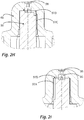
- the embodiment of the Figures 3A to 3G including a variant of the Figure 3H has a modification which in particular serves the purpose of ensuring the tightness in the area of the end face 53B and of preventing discharge in a particularly reliable manner by means of a switching valve.
- Figures 3A and 3B show the position of inner component 50 and outer component 60 in a position for generating a spray jet.
- Figures 3C and 3D show the position of inner component 50 and outer component 60 in a position for generating a non-atomized jet.
- the inner component 50 is not integrally connected to the base 20 and the actuating handle 30, but instead formed as a separate component 50, which is pushed axially onto a pin 82, which is part of a guide component 80, which in this specific case is integral with the actuating surface 32 and the base 20 is executed.
- the guide component 80 could also be formed separately from the components 32 and 20 and only be firmly attached to one of them.
- a spring device 70 is also provided in this configuration, which is formed by clamping surfaces 65, 85, which in this case are provided on the guide component 80 and the outer component 60 and press the outer component 60 against the inner component 50 at the end.
- the inner component 50 which is shown in Figure 3F is shown separately again, has a sleeve structure open on both sides. With its end pointing away from the discharge opening 98, it is pushed onto the named pin 82 of the guide component 80. Ribs 87 and recesses 57 in the in Figure 3B and 3D illustrated way created a rotation lock. The inner component 50 is therefore secured against rotation, but is basically axially displaceable, attached to the guide component 80.
- the inner component 50 has a piston surface 54 at the end and its outer side rests in a sealing manner on a sliding surface 84 of a sleeve section 86 of the guide component 80.
- the inner component 50 merges into an end region 53 which corresponds to the structure with regard to its structure and in particular the supply grooves 97A and 97D Figure 2E corresponds to.
- the inner component is also designed to be open in this direction and has an opening 59 for this purpose. Beyond this opening, a further piston surface 51 is provided, which on the outside rests against a sliding surface 61 of the outer component 60.
- This second piston surface 51 or its effective cross section is smaller than the piston surface 54 or its effective cross section.
- the Figure 3B and 3D further illustrate latching positions of the inner component 50 and the outer component 60 with respect to one another, wherein in the case of the design Figures 3A to 3H These latching positions are made possible by external recesses 89 on the sleeve section 86 of the guide component 80 and inwardly pointing latching webs 69 on the outer component 60.
- latching webs 69 When the locking webs 69 into the recesses 89 are engaged, an increased force is required in order to rotate the outer component 60 relative to the inner component 50 and the guide component 80. If the components are rotated relative to one another, the latching webs 69 snap into the recesses 89 and thus signal to the user that a particular rotational position is involved.
- Figure 3E shows a further sectional view. It can be seen here that the outer component 60 is provided with inwardly pointing radial ribs 62. These have a shape with which they form the aforementioned locking webs 69 for forming the locking positions in an upper region. A lower area 67, on the other hand, rests on the outside of the clamping surface 85. The effect of this lower region 67 is that the outer component 60 can only be deformed to a small extent and therefore there is no risk of it becoming detached from the inner component 50 and the guide component 80 under the action of liquid pressure.
- FIGS 3F and 3G show similarly the Figures 2E and 2G the inflow grooves 97B, 97D and the supply grooves 97A, 97C. Their mode of operation corresponds to that already explained: By changing the rotational position between the inner component 50 and the outer component 60, the liquid is fed either along a first liquid path through the supply grooves 97A into the inflow grooves 97B or along a second liquid path through the supply grooves 97C into the inflow grooves 97D. If none of these liquid paths is open, the liquid cannot reach the discharge opening 98.
- a switching valve 99 is additionally provided, which is formed by two stages 99A, 99C in the outer component 60 and inner component 50 and by interruptions 99B, 99D provided therein.
- the interruptions 99B, 99D are aligned in such a way that liquid can flow through the switching valve 99.
- the switching valve 99 cuts off the supply of liquid to the supply grooves 97A, 97C.
- the piston-like configuration of the inner component 50 is suitable for permanently pressing it in the direction of the discharge opening 98 when the liquid pressure is applied. This creates a particular degree of tightness between the surfaces 53B, 63B which bear against one another. The special tightness ensures that both the application of a jet and a spray jet are possible in particularly good quality. Liquid only reaches the discharge opening 98 through the grooves 97A-97D, but not through an undesired gap between the end face 53B and the end face inner face 63B.
- Figure 3H shows a slightly modified variant of the embodiment of FIG Figures 3A to 3G .
- an additional spring device 71 in the form of a helical compression spring is provided between the guide component 80 and the inner component 50, which permanently presses the inner component 50 on the end face against the outer component 60.
- the piston-like mode of operation of the inner component 50 can be dispensed with.
- this is preferably retained despite the spring device 71.
Landscapes
- Health & Medical Sciences (AREA)
- Engineering & Computer Science (AREA)
- Animal Behavior & Ethology (AREA)
- General Health & Medical Sciences (AREA)
- Veterinary Medicine (AREA)
- Anesthesiology (AREA)
- Biomedical Technology (AREA)
- Heart & Thoracic Surgery (AREA)
- Hematology (AREA)
- Life Sciences & Earth Sciences (AREA)
- Public Health (AREA)
- Mechanical Engineering (AREA)
- Bioinformatics & Cheminformatics (AREA)
- Pulmonology (AREA)
- Chemical & Material Sciences (AREA)
- Dispersion Chemistry (AREA)
- Otolaryngology (AREA)
- Vascular Medicine (AREA)
- Containers And Packaging Bodies Having A Special Means To Remove Contents (AREA)
- Infusion, Injection, And Reservoir Apparatuses (AREA)
Claims (15)
- Tête de distribution (10) destinée à l'application nasale d'un liquide pharmaceutique provenant d'un réservoir de pression (110) qui dispose d'une soupape de sortie (112) pourvue d'un ajutage de valve (114) qui peut être actionné par une force s'opposant à une force de ressort pour ouvrir la soupape de sortie (112), la tête de distribution présentant les caractéristiques suivantes :a. la tête de distribution (10) dispose d'un applicateur nasal (12) destiné à être introduit dans la narine d'un utilisateur, l'applicateur nasal (12) ayant une forme allongée et mince se rétrécissant vers une extrémité distale et une ouverture de distribution (98) étant prévue à l'extrémité distale de l'applicateur nasal (12), laquelle ouverture est reliée à une entrée de l'applicateur nasal par le biais d'un conduit (92) de l'applicateur nasal (12),b. l'applicateur nasal (12) dispose d'un composant intérieur (50), etc. l'applicateur nasal (12) dispose d'un composant extérieur (60) qui est conçu comme un composant qui est séparé du composant intérieur (50) et qui est fixé de manière rotative au composant intérieur (50) en entourant celui-ci,d. l'ouverture de distribution (98) est prévue sous la forme d'un passage qui est ménagé dans le composant extérieur (60) et qui est entouré du côté intérieur par une surface intérieure côté frontal (63B), ete. une surface frontale (53B) du composant intérieur (50) est prévue en face de la surface intérieure côté frontal (63B) et vient en appui de manière sensiblement bidimensionnelle sur la surface intérieure côté frontal (63B), etf. au moins deux conduits d'entrée se présentant sous la forme de rainures d'entrée d'écoulement (97B, 97D) sont formés sur la surface intérieure côté frontal (63B) du composant extérieur (60) et/ou la surface frontale (53B) du composant intérieur (50) et sont reliés à une zone d'entrée d'écoulement (58) en amont des rainures d'entrée d'écoulement (97B, 97D), ou séparés de celle-ci, en fonction d'une position en rotation du composant extérieur (60) par rapport au composant intérieur (50).
- Tête de distribution (10) selon la revendication 1 présentant la caractéristique suivante :a. deux types de rainures d'entrée d'écoulement (97B, 97D) sont prévus, à savoir au moins une rainure radiale (97D) orientée sensiblement radialement et au moins une rainure tangentielle (97B) coudée par rapport à l'ouverture de distribution,de préférence présentant la caractéristique supplémentaire suivante :
b. une pluralité de rainures radiales (97D) et/ou une pluralité de rainures tangentielles (97B) sont prévues. - Tête de distribution (10) selon la revendication 1 ou 2 présentant la caractéristique suivante :a. au moins une rainure d'entrée d'écoulement (97B) est prévue dans la surface intérieure côté frontal (63B) du composant extérieur (60) et au moins une rainure d'entrée d'écoulement (97D) est prévue dans la surface frontale (53B) du composant intérieur (50),de préférence présentant la caractéristique supplémentaire suivante :
b. l'au moins une rainure radiale (97D) est prévue sur la surface intérieure côté frontal du composant extérieur ou sur la surface frontale (53B) du composant intérieur (50) et l'au moins une rainure tangentielle (97B) est prévue sur la surface opposée (63B). - Tête de distribution (10) selon l'une des revendications précédentes présentant les caractéristiques suivantes :a. le composant extérieur (60) comporte une surface intérieure cylindrique (63A) adjacente à la surface intérieure côté frontal (63B) de celui-ci, etb. le composant intérieur (50) comporte une surface extérieure cylindrique (53A) adjacente à la surface frontale (53B) de celui-ci, etc. la surface intérieure cylindrique (63A) et la surface extérieure cylindrique (53A) viennent en appui l'une sur l'autre de manière étanche, etd. au moins une des deux surfaces comprenant la surface intérieure cylindrique (63A) et la surface extérieure cylindrique (53A) est pourvue d'une rainure d'alimentation (97A, 97C) permettant d'alimenter au moins une rainure d'entrée d'écoulement (97B, 97D) en liquide provenant de la zone d'entrée d'écoulement (58) .
- Tête de distribution (10) selon la revendication 4 présentant la caractéristique suivante :a. la surface intérieure cylindrique (63A) et la surface extérieure cylindrique (53A) comportent toutes deux au moins une rainure d'alimentation (97A, 97C) destinée à alimenter l'au moins une rainure d'entrée d'écoulement (97B, 97D) en liquide provenant de la zone d'entrée d'écoulement (58).
- Tête de distribution (10) selon la revendication 4 ou 5 présentant l'une au moins des caractéristiques suivantes :a. la surface extérieure cylindrique (53A) du composant intérieur (50) comporte au moins une rainure d'alimentation (97A) qui s'étend jusqu'à la surface frontale (53B) du composant intérieur et/oub. la surface intérieure cylindrique (63A) du composant extérieur (60) comporte au moins une rainure d'alimentation (97C) qui ne s'étend pas jusqu'à la surface intérieure côté frontal (63B) du composant extérieur (60).
- Tête de distribution (10) selon l'une des revendications précédentes présentant la caractéristique supplémentaire suivante :a. la zone d'entrée d'écoulement (58) comporte en amont des rainures d'entrée d'écoulement (97B, 97D) une soupape de commutation (99) qui interrompt l'alimentation en liquide des rainures d'entrée d'écoulement (97B, 97D) en fonction de la position en rotation du composant extérieur (60) par rapport au composant intérieur (50),de préférence présentant la caractéristique supplémentaire :
b. la soupape de commutation est prévue en amont des rainures d'alimentation (97A, 97C) destinées à alimenter les rainures d'entrée d'écoulement (97B, 97D) . - Tête de distribution (10) selon l'une des revendications précédentes présentant la caractéristique supplémentaire suivante :a. le composant intérieur (50) et le composant extérieur (60) sont pressés l'un sur l'autre avec un dispositif à ressort (70),en particulier présentant la caractéristique supplémentaire suivante :
b. le composant extérieur (60) et le composant intérieur (50) comportent des surfaces de serrage inclinées (55, 65) qui sont pressées l'une sur l'autre dans une direction radiale par déformation élastique du composant intérieur (50) ou du composant extérieur (60) et qui pressent ainsi indirectement le composant extérieur (60) et le composant intérieur (50) l'un sur l'autre. - Tête de distribution (10) selon la revendication 8 présentant la caractéristique supplémentaire suivante :a. le composant intérieur (50) et/ou le composant extérieur (60) ont une forme, s'écartant de la forme circulaire, des surfaces de serrage (55, 65) ou d'autres surfaces de contact, de sorte que, lorsque le composant extérieur (60) tourne par rapport au composant intérieur (50), l'un au moins des composants (50, 60) présente une déformation variable qui est minime notamment dans deux positions extrêmes.
- Tête de distribution (10) selon l'une des revendications précédentes présentant les caractéristiques supplémentaires suivantes :a. la tête de distribution (10) dispose d'une base (20) et d'un dispositif d'accouplement, prévu sur celle-ci, qui permettent de fixer la tête de distribution (10) au réservoir sous pression (110), etb. la tête de distribution (10) dispose d'une surface d'actionnement déplaçable (32) qui peut être déplacée par rapport à la base (20) et sur laquelle est prévu un poussoir (40) qui est conçu comme un tube creux (42) et qui peut être déplacé conjointement avec la surface d'actionnement (32) pour appliquer une force sur l'ajutage de soupape (114) du réservoir sous pression (110), etc. l'applicateur nasal (12) s'étend vers l'extérieur depuis la surface d'actionnement (32).
- Tête de distribution (10) selon la revendication 10 présentant la caractéristique supplémentaire suivante :a. le composant intérieur (50) de l'applicateur nasal (12) est relié d'une seule pièce à la surface d'actionnement (32).
- Tête de distribution (10) selon la revendication 10 présentant les caractéristiques supplémentaires suivantes :a. la tête de distribution comporte un composant de guidage (80), etb. le composant intérieur (50) est fixé au composant de guidage (80) de manière déplaçable axialement et fixe en rotation, etc. le composant extérieur (60) est fixé de manière rotative au composant de guidage (80),en particulier présentant la caractéristique supplémentaire suivante :
d. le composant de guidage (80) est formé d'une seule pièce avec la surface d'actionnement (32) et/ou la base (20) . - Tête de distribution (10) selon la revendication 12 présentant la caractéristique supplémentaire suivante :a. le composant intérieur (50) et le composant de guidage (80) délimitent conjointement une chambre sous pression (88), le composant intérieur (50) comportant une surface de piston (54) qui est dirigée vers la chambre sous pression (88) et qui est soumise à une force qui agit en direction de l'ouverture de distribution (98) par le biais de la pression de fluide dans la chambre sous pression (88).
- Tête de distribution (10) selon l'une des revendications précédentes présentant la caractéristique supplémentaire suivante :a. un dispositif à ressort (70) est prévu qui agit entre le composant de guidage (80) et le composant extérieur (60) et/ou un dispositif à ressort (71) est prévu qui agit entre le composant de guidage (80) et le composant intérieur (50),en particulier présentant au moins une des caractéristiques supplémentaires suivantes :b. le composant extérieur (60) et le composant de guidage (80) comportent des surfaces de serrage inclinées (85, 65) qui sont pressées l'une sur l'autre dans une direction radiale par déformation élastique du composant de guidage (80) ou du composant extérieur (60) et qui pressent ainsi indirectement le composant extérieur (60) et le composant de guidage (80) l'un sur l'autre, et/ouc. le composant de guidage (80) et/ou le composant extérieur (60) ont une forme, s'écartant de la forme circulaire, des surfaces de serrage (85, 65) ou d'autres surfaces de contact (69, 89) de sorte que, lorsque le composant extérieur (60) tourne par rapport au composant de guidage (80), l'un au moins des composants (80, 60) présente une déformation variable qui est minime notamment dans deux positions extrêmes, ou dans deux positions extrêmes et au moins dans une position intermédiaire, et/oud. et un ressort de compression (71) est prévu entre le composant de guidage (80) et le composant intérieur (50) et presse le composant intérieur (50) contre le composant extérieur (60).
- Distributeur (100) destiné la distribution de liquides pharmaceutiques, le distributeur présentant les caractéristiques suivantes :a. le distributeur (100) dispose d'un réservoir sous pression (110) dans lequel un liquide pharmaceutique est stocké sous pression et qui dispose à son tour d'une soupape de sortie (112), etb. la soupape de sortie (112) dispose d'un ajutage de soupape (114) qui peut être soumis à une force, s'opposant à une force de ressort, pour ouvrir la soupape, etc. le distributeur (100) comporte une tête de distribution (10) destinée à s'accoupler au réservoir sous pression (110),caractérisé par la caractéristique :
d. la tête de distribution (10) est conçue selon l'une des revendications précédentes.
Priority Applications (1)
| Application Number | Priority Date | Filing Date | Title |
|---|---|---|---|
| RU2019109788A RU2737583C2 (ru) | 2017-06-08 | 2019-04-03 | Выпускная головка для интраназального введения жидкости из емкости, находящейся под давлением |
Applications Claiming Priority (2)
| Application Number | Priority Date | Filing Date | Title |
|---|---|---|---|
| EP17175093.8A EP3412325B1 (fr) | 2017-06-08 | 2017-06-08 | Tête distributrice pour l'application nasale de liquide provenant d'un accumulateur de pression |
| PCT/EP2018/059583 WO2018224206A1 (fr) | 2017-06-08 | 2018-04-13 | Tête de diffusion pour l'application nasale d'un liquide à partir d'un accumulateur de pression |
Publications (2)
| Publication Number | Publication Date |
|---|---|
| EP3552644A1 EP3552644A1 (fr) | 2019-10-16 |
| EP3552644B1 true EP3552644B1 (fr) | 2021-07-07 |
Family
ID=59053970
Family Applications (2)
| Application Number | Title | Priority Date | Filing Date |
|---|---|---|---|
| EP17175093.8A Active EP3412325B1 (fr) | 2017-06-08 | 2017-06-08 | Tête distributrice pour l'application nasale de liquide provenant d'un accumulateur de pression |
| EP18209877.2A Active EP3552644B1 (fr) | 2017-06-08 | 2018-12-03 | Tête distributrice pour l'application nasale de liquide provenant d'un accumulateur de pression |
Family Applications Before (1)
| Application Number | Title | Priority Date | Filing Date |
|---|---|---|---|
| EP17175093.8A Active EP3412325B1 (fr) | 2017-06-08 | 2017-06-08 | Tête distributrice pour l'application nasale de liquide provenant d'un accumulateur de pression |
Country Status (6)
| Country | Link |
|---|---|
| US (2) | US11833295B2 (fr) |
| EP (2) | EP3412325B1 (fr) |
| CN (2) | CN110740772B (fr) |
| BR (1) | BR112019023811B1 (fr) |
| RU (1) | RU2737583C2 (fr) |
| WO (1) | WO2018224206A1 (fr) |
Families Citing this family (7)
| Publication number | Priority date | Publication date | Assignee | Title |
|---|---|---|---|---|
| US10464736B1 (en) * | 2017-09-21 | 2019-11-05 | The B'Laster Corporation | Spray can actuator |
| USD935318S1 (en) | 2019-07-24 | 2021-11-09 | Aptar Radolfzell Gmbh | Spray head |
| GB2597471A (en) * | 2020-07-22 | 2022-02-02 | Innovolo Ltd | Aerosol canister cap |
| BE1029771B1 (nl) * | 2021-09-20 | 2023-04-17 | Soudal | Handbedieningsapplicator voor polyurethaan (pu) schuim |
| GB202202890D0 (en) * | 2022-03-02 | 2022-04-13 | Consort Medical Ltd | Improvements relating to nasal pieces |
| EP4368227A1 (fr) * | 2022-11-09 | 2024-05-15 | Aptar Radolfzell GmbH | Distributeur de liquide pour application nasale et dispositif de pompage |
| USD1006983S1 (en) * | 2023-03-13 | 2023-12-05 | ChongQing Moffy Innovation Technology Co., Ltd. | Nasal irrigator nozzle |
Family Cites Families (20)
| Publication number | Priority date | Publication date | Assignee | Title |
|---|---|---|---|---|
| US3961756A (en) * | 1975-02-10 | 1976-06-08 | National Chemsearch Corporation | Adjustable-spray mechanism |
| US4358057A (en) | 1980-05-27 | 1982-11-09 | Ethyl Products Company | Fluid dispenser method and apparatus |
| US4706888A (en) | 1986-07-11 | 1987-11-17 | Calmar, Inc. | Multi-purpose nozzle assembly |
| US5590837A (en) | 1995-02-28 | 1997-01-07 | Calmar Inc. | Sprayer having variable spray pattern |
| FR2781772B1 (fr) * | 1998-07-31 | 2000-10-13 | Sofab | Distributeur de produits liquides destines a etre delivres par pulverisation |
| US5996653A (en) | 1998-10-08 | 1999-12-07 | Eastman Kodak Company | Valve assembly and apparatus |
| RU28026U1 (ru) | 2002-08-15 | 2003-03-10 | Общество с ограниченной ответственностью "Паркинфарм" | Устройство для дозированного введения лекарственного средства |
| FR2886172B1 (fr) * | 2005-05-25 | 2008-01-25 | Soppec Soc Par Actions Simplif | Dispositif diffuseur a jets multiples pour bombes aerosols |
| US7861894B2 (en) * | 2007-08-22 | 2011-01-04 | Seaquistperfect Dispensing L.L.C. | Lockable dispenser |
| FR2952042B1 (fr) * | 2009-11-03 | 2012-01-20 | Valois Sas | Dispositif de distribution de produit fluide. |
| USD659531S1 (en) | 2010-05-10 | 2012-05-15 | Ep Systems Sa | Nozzle |
| DE102011007396A1 (de) | 2011-04-14 | 2012-10-18 | Ing. Erich Pfeiffer Gmbh | Austragkopf für eine Tube und Tube mit Austragkopf |
| DE102011082420B4 (de) | 2011-09-09 | 2021-02-04 | Aptar Radolfzell Gmbh | Flüssigkeitsspender und Austragskopf für einen Flüssigkeitsspender |
| DE102012200545A1 (de) | 2012-01-16 | 2013-07-18 | Aptar Radolfzell Gmbh | Medienspender |
| DE102013001931B4 (de) | 2013-02-02 | 2016-03-31 | Neoperl Gmbh | Sanitäre Einsetzeinheit |
| EP2796206B1 (fr) | 2013-04-26 | 2016-12-21 | Aptar Radolfzell GmbH | Tête de distribution associée à un récipient et procédé de fixation d'une tête de distribution sur un récipient |
| EP2868334B1 (fr) | 2013-11-05 | 2017-01-11 | Benedict Gerber | Douche nasale |
| DE102014000425A1 (de) | 2014-01-17 | 2015-07-23 | Aptar Dortmund Gmbh | Abgabevorrichtung |
| FR3034326B1 (fr) | 2015-03-30 | 2020-02-07 | Yslab | Tete de pulverisation universelle et securitaire pour pulverisateur |
| ITUB20152886A1 (it) * | 2015-08-05 | 2017-02-05 | Eleuterio Pollini | Dispositivo di sicurezza per l'irrigazione nasale |
-
2017
- 2017-06-08 EP EP17175093.8A patent/EP3412325B1/fr active Active
-
2018
- 2018-04-13 BR BR112019023811-5A patent/BR112019023811B1/pt active IP Right Grant
- 2018-04-13 CN CN201880038259.1A patent/CN110740772B/zh active Active
- 2018-04-13 WO PCT/EP2018/059583 patent/WO2018224206A1/fr active Application Filing
- 2018-04-13 CN CN202210280372.9A patent/CN114655585A/zh active Pending
- 2018-04-13 US US16/615,245 patent/US11833295B2/en active Active
- 2018-12-03 EP EP18209877.2A patent/EP3552644B1/fr active Active
-
2019
- 2019-04-03 RU RU2019109788A patent/RU2737583C2/ru active
-
2023
- 2023-08-21 US US18/452,797 patent/US20230398316A1/en active Pending
Also Published As
| Publication number | Publication date |
|---|---|
| US11833295B2 (en) | 2023-12-05 |
| RU2019109788A3 (fr) | 2020-10-05 |
| US20200171252A1 (en) | 2020-06-04 |
| US20230398316A1 (en) | 2023-12-14 |
| EP3412325B1 (fr) | 2019-09-25 |
| BR112019023811A2 (pt) | 2020-06-02 |
| RU2737583C2 (ru) | 2020-12-01 |
| BR112019023811B1 (pt) | 2024-01-02 |
| EP3552644A1 (fr) | 2019-10-16 |
| CN110740772A (zh) | 2020-01-31 |
| CN114655585A (zh) | 2022-06-24 |
| CN110740772B (zh) | 2022-03-29 |
| WO2018224206A1 (fr) | 2018-12-13 |
| RU2019109788A (ru) | 2020-10-05 |
| EP3412325A1 (fr) | 2018-12-12 |
Similar Documents
| Publication | Publication Date | Title |
|---|---|---|
| EP3552644B1 (fr) | Tête distributrice pour l'application nasale de liquide provenant d'un accumulateur de pression | |
| EP0923993B1 (fr) | Distributeur de fluide | |
| EP2804504B1 (fr) | Distributeur de fluides | |
| DE69919321T2 (de) | Zerstäubungskopf für einen spender für medien | |
| EP2179674B1 (fr) | Unité cosmétique dotée d'un essoreur réglable | |
| EP3984652B1 (fr) | Distributeur de liquide | |
| DE602004005607T2 (de) | Fluidproduktabgabekopf | |
| DE60320607T2 (de) | Einheit zur Verpackung und zur Ausgabe eines Produkts, insbesondere in Form einer Probe | |
| EP0815946A2 (fr) | Distributeur pour fluides | |
| DE3315334A1 (de) | Zerstaeuber- oder dosierpumpe | |
| EP0312722A1 (fr) | Pompe de dosage et d'atomisation pour matières liquides ou visqueuses | |
| EP2134475A1 (fr) | Dispositif pour pulvériser des liquides pigmentés | |
| EP2461860A2 (fr) | Dispositif de distribution d'agents liquides | |
| EP0953515A2 (fr) | Distributeur de fluide | |
| WO2018171986A1 (fr) | Distributeur de liquide à éponge de distribution | |
| EP2654967B1 (fr) | Distributeur pour un liquide | |
| EP0829307B1 (fr) | Distributeur de fluides | |
| EP0982075B1 (fr) | Distributeur de fluides | |
| DE602004010148T2 (de) | Schaumdüse | |
| EP2158136B1 (fr) | Dispositif de déversement d'une substance apte à l'écoulement | |
| EP0923994A1 (fr) | Distributeur de fluide | |
| EP3787983B1 (fr) | Distributeur de creme | |
| DE202005012686U1 (de) | Tuben-Verschlussstück | |
| DE2425951B2 (de) | Einstueckig ausgebildeter spruehkopf fuer eine aerosol-druckdose und form zu seiner herstellung | |
| EP1118554A1 (fr) | Capuchon de pulvérisation avec tête intégrée |
Legal Events
| Date | Code | Title | Description |
|---|---|---|---|
| PUAI | Public reference made under article 153(3) epc to a published international application that has entered the european phase |
Free format text: ORIGINAL CODE: 0009012 |
|
| STAA | Information on the status of an ep patent application or granted ep patent |
Free format text: STATUS: THE APPLICATION HAS BEEN PUBLISHED |
|
| AK | Designated contracting states |
Kind code of ref document: A1 Designated state(s): AL AT BE BG CH CY CZ DE DK EE ES FI FR GB GR HR HU IE IS IT LI LT LU LV MC MK MT NL NO PL PT RO RS SE SI SK SM TR |
|
| AX | Request for extension of the european patent |
Extension state: BA ME |
|
| STAA | Information on the status of an ep patent application or granted ep patent |
Free format text: STATUS: REQUEST FOR EXAMINATION WAS MADE |
|
| 17P | Request for examination filed |
Effective date: 20200416 |
|
| RBV | Designated contracting states (corrected) |
Designated state(s): AL AT BE BG CH CY CZ DE DK EE ES FI FR GB GR HR HU IE IS IT LI LT LU LV MC MK MT NL NO PL PT RO RS SE SI SK SM TR |
|
| GRAP | Despatch of communication of intention to grant a patent |
Free format text: ORIGINAL CODE: EPIDOSNIGR1 |
|
| STAA | Information on the status of an ep patent application or granted ep patent |
Free format text: STATUS: GRANT OF PATENT IS INTENDED |
|
| RIC1 | Information provided on ipc code assigned before grant |
Ipc: A61M 15/00 20060101AFI20210308BHEP Ipc: A61M 15/08 20060101ALI20210308BHEP Ipc: B65D 83/14 20060101ALI20210308BHEP Ipc: A61M 11/00 20060101ALI20210308BHEP Ipc: B65D 83/20 20060101ALI20210308BHEP Ipc: B65D 83/22 20060101ALI20210308BHEP Ipc: B05B 1/12 20060101ALI20210308BHEP Ipc: B05B 1/34 20060101ALI20210308BHEP Ipc: B05B 1/00 20060101ALI20210308BHEP Ipc: B65D 83/30 20060101ALN20210308BHEP Ipc: B65D 83/46 20060101ALN20210308BHEP |
|
| INTG | Intention to grant announced |
Effective date: 20210324 |
|
| RIN1 | Information on inventor provided before grant (corrected) |
Inventor name: GREINER-PERTH, JUERGEN Inventor name: SCHMID, FELIX |
|
| GRAS | Grant fee paid |
Free format text: ORIGINAL CODE: EPIDOSNIGR3 |
|
| GRAA | (expected) grant |
Free format text: ORIGINAL CODE: 0009210 |
|
| STAA | Information on the status of an ep patent application or granted ep patent |
Free format text: STATUS: THE PATENT HAS BEEN GRANTED |
|
| AK | Designated contracting states |
Kind code of ref document: B1 Designated state(s): AL AT BE BG CH CY CZ DE DK EE ES FI FR GB GR HR HU IE IS IT LI LT LU LV MC MK MT NL NO PL PT RO RS SE SI SK SM TR |
|
| REG | Reference to a national code |
Ref country code: GB Ref legal event code: FG4D Free format text: NOT ENGLISH |
|
| REG | Reference to a national code |
Ref country code: AT Ref legal event code: REF Ref document number: 1407947 Country of ref document: AT Kind code of ref document: T Effective date: 20210715 |
|
| REG | Reference to a national code |
Ref country code: DE Ref legal event code: R096 Ref document number: 502018006001 Country of ref document: DE |
|
| REG | Reference to a national code |
Ref country code: IE Ref legal event code: FG4D Free format text: LANGUAGE OF EP DOCUMENT: GERMAN |
|
| REG | Reference to a national code |
Ref country code: LT Ref legal event code: MG9D |
|
| REG | Reference to a national code |
Ref country code: NL Ref legal event code: MP Effective date: 20210707 |
|
| PG25 | Lapsed in a contracting state [announced via postgrant information from national office to epo] |
Ref country code: HR Free format text: LAPSE BECAUSE OF FAILURE TO SUBMIT A TRANSLATION OF THE DESCRIPTION OR TO PAY THE FEE WITHIN THE PRESCRIBED TIME-LIMIT Effective date: 20210707 Ref country code: ES Free format text: LAPSE BECAUSE OF FAILURE TO SUBMIT A TRANSLATION OF THE DESCRIPTION OR TO PAY THE FEE WITHIN THE PRESCRIBED TIME-LIMIT Effective date: 20210707 Ref country code: FI Free format text: LAPSE BECAUSE OF FAILURE TO SUBMIT A TRANSLATION OF THE DESCRIPTION OR TO PAY THE FEE WITHIN THE PRESCRIBED TIME-LIMIT Effective date: 20210707 Ref country code: RS Free format text: LAPSE BECAUSE OF FAILURE TO SUBMIT A TRANSLATION OF THE DESCRIPTION OR TO PAY THE FEE WITHIN THE PRESCRIBED TIME-LIMIT Effective date: 20210707 Ref country code: SE Free format text: LAPSE BECAUSE OF FAILURE TO SUBMIT A TRANSLATION OF THE DESCRIPTION OR TO PAY THE FEE WITHIN THE PRESCRIBED TIME-LIMIT Effective date: 20210707 Ref country code: PT Free format text: LAPSE BECAUSE OF FAILURE TO SUBMIT A TRANSLATION OF THE DESCRIPTION OR TO PAY THE FEE WITHIN THE PRESCRIBED TIME-LIMIT Effective date: 20211108 Ref country code: NO Free format text: LAPSE BECAUSE OF FAILURE TO SUBMIT A TRANSLATION OF THE DESCRIPTION OR TO PAY THE FEE WITHIN THE PRESCRIBED TIME-LIMIT Effective date: 20211007 Ref country code: NL Free format text: LAPSE BECAUSE OF FAILURE TO SUBMIT A TRANSLATION OF THE DESCRIPTION OR TO PAY THE FEE WITHIN THE PRESCRIBED TIME-LIMIT Effective date: 20210707 Ref country code: LT Free format text: LAPSE BECAUSE OF FAILURE TO SUBMIT A TRANSLATION OF THE DESCRIPTION OR TO PAY THE FEE WITHIN THE PRESCRIBED TIME-LIMIT Effective date: 20210707 Ref country code: BG Free format text: LAPSE BECAUSE OF FAILURE TO SUBMIT A TRANSLATION OF THE DESCRIPTION OR TO PAY THE FEE WITHIN THE PRESCRIBED TIME-LIMIT Effective date: 20211007 |
|
| PG25 | Lapsed in a contracting state [announced via postgrant information from national office to epo] |
Ref country code: PL Free format text: LAPSE BECAUSE OF FAILURE TO SUBMIT A TRANSLATION OF THE DESCRIPTION OR TO PAY THE FEE WITHIN THE PRESCRIBED TIME-LIMIT Effective date: 20210707 Ref country code: LV Free format text: LAPSE BECAUSE OF FAILURE TO SUBMIT A TRANSLATION OF THE DESCRIPTION OR TO PAY THE FEE WITHIN THE PRESCRIBED TIME-LIMIT Effective date: 20210707 Ref country code: GR Free format text: LAPSE BECAUSE OF FAILURE TO SUBMIT A TRANSLATION OF THE DESCRIPTION OR TO PAY THE FEE WITHIN THE PRESCRIBED TIME-LIMIT Effective date: 20211008 |
|
| REG | Reference to a national code |
Ref country code: DE Ref legal event code: R097 Ref document number: 502018006001 Country of ref document: DE |
|
| REG | Reference to a national code |
Ref country code: DE Ref legal event code: R082 Ref document number: 502018006001 Country of ref document: DE Representative=s name: WITTE, WELLER & PARTNER PATENTANWAELTE MBB, DE |
|
| PG25 | Lapsed in a contracting state [announced via postgrant information from national office to epo] |
Ref country code: DK Free format text: LAPSE BECAUSE OF FAILURE TO SUBMIT A TRANSLATION OF THE DESCRIPTION OR TO PAY THE FEE WITHIN THE PRESCRIBED TIME-LIMIT Effective date: 20210707 |
|
| PLBE | No opposition filed within time limit |
Free format text: ORIGINAL CODE: 0009261 |
|
| STAA | Information on the status of an ep patent application or granted ep patent |
Free format text: STATUS: NO OPPOSITION FILED WITHIN TIME LIMIT |
|
| PG25 | Lapsed in a contracting state [announced via postgrant information from national office to epo] |
Ref country code: SM Free format text: LAPSE BECAUSE OF FAILURE TO SUBMIT A TRANSLATION OF THE DESCRIPTION OR TO PAY THE FEE WITHIN THE PRESCRIBED TIME-LIMIT Effective date: 20210707 Ref country code: SK Free format text: LAPSE BECAUSE OF FAILURE TO SUBMIT A TRANSLATION OF THE DESCRIPTION OR TO PAY THE FEE WITHIN THE PRESCRIBED TIME-LIMIT Effective date: 20210707 Ref country code: RO Free format text: LAPSE BECAUSE OF FAILURE TO SUBMIT A TRANSLATION OF THE DESCRIPTION OR TO PAY THE FEE WITHIN THE PRESCRIBED TIME-LIMIT Effective date: 20210707 Ref country code: EE Free format text: LAPSE BECAUSE OF FAILURE TO SUBMIT A TRANSLATION OF THE DESCRIPTION OR TO PAY THE FEE WITHIN THE PRESCRIBED TIME-LIMIT Effective date: 20210707 Ref country code: CZ Free format text: LAPSE BECAUSE OF FAILURE TO SUBMIT A TRANSLATION OF THE DESCRIPTION OR TO PAY THE FEE WITHIN THE PRESCRIBED TIME-LIMIT Effective date: 20210707 Ref country code: AL Free format text: LAPSE BECAUSE OF FAILURE TO SUBMIT A TRANSLATION OF THE DESCRIPTION OR TO PAY THE FEE WITHIN THE PRESCRIBED TIME-LIMIT Effective date: 20210707 |
|
| 26N | No opposition filed |
Effective date: 20220408 |
|
| PG25 | Lapsed in a contracting state [announced via postgrant information from national office to epo] |
Ref country code: MC Free format text: LAPSE BECAUSE OF FAILURE TO SUBMIT A TRANSLATION OF THE DESCRIPTION OR TO PAY THE FEE WITHIN THE PRESCRIBED TIME-LIMIT Effective date: 20210707 |
|
| REG | Reference to a national code |
Ref country code: CH Ref legal event code: PL |
|
| REG | Reference to a national code |
Ref country code: BE Ref legal event code: MM Effective date: 20211231 |
|
| PG25 | Lapsed in a contracting state [announced via postgrant information from national office to epo] |
Ref country code: LU Free format text: LAPSE BECAUSE OF NON-PAYMENT OF DUE FEES Effective date: 20211203 Ref country code: IE Free format text: LAPSE BECAUSE OF NON-PAYMENT OF DUE FEES Effective date: 20211203 |
|
| PG25 | Lapsed in a contracting state [announced via postgrant information from national office to epo] |
Ref country code: BE Free format text: LAPSE BECAUSE OF NON-PAYMENT OF DUE FEES Effective date: 20211231 |
|
| PG25 | Lapsed in a contracting state [announced via postgrant information from national office to epo] |
Ref country code: LI Free format text: LAPSE BECAUSE OF NON-PAYMENT OF DUE FEES Effective date: 20211231 Ref country code: CH Free format text: LAPSE BECAUSE OF NON-PAYMENT OF DUE FEES Effective date: 20211231 |
|
| P01 | Opt-out of the competence of the unified patent court (upc) registered |
Effective date: 20230502 |
|
| PG25 | Lapsed in a contracting state [announced via postgrant information from national office to epo] |
Ref country code: CY Free format text: LAPSE BECAUSE OF FAILURE TO SUBMIT A TRANSLATION OF THE DESCRIPTION OR TO PAY THE FEE WITHIN THE PRESCRIBED TIME-LIMIT Effective date: 20210707 |
|
| PG25 | Lapsed in a contracting state [announced via postgrant information from national office to epo] |
Ref country code: HU Free format text: LAPSE BECAUSE OF FAILURE TO SUBMIT A TRANSLATION OF THE DESCRIPTION OR TO PAY THE FEE WITHIN THE PRESCRIBED TIME-LIMIT; INVALID AB INITIO Effective date: 20181203 |
|
| PGFP | Annual fee paid to national office [announced via postgrant information from national office to epo] |
Ref country code: GB Payment date: 20231220 Year of fee payment: 6 |
|
| PGFP | Annual fee paid to national office [announced via postgrant information from national office to epo] |
Ref country code: FR Payment date: 20231220 Year of fee payment: 6 Ref country code: DE Payment date: 20231004 Year of fee payment: 6 |
|
| PG25 | Lapsed in a contracting state [announced via postgrant information from national office to epo] |
Ref country code: MK Free format text: LAPSE BECAUSE OF FAILURE TO SUBMIT A TRANSLATION OF THE DESCRIPTION OR TO PAY THE FEE WITHIN THE PRESCRIBED TIME-LIMIT Effective date: 20210707 |
|
| PGFP | Annual fee paid to national office [announced via postgrant information from national office to epo] |
Ref country code: IT Payment date: 20231229 Year of fee payment: 6 |