EP2868334B1 - Douche nasale - Google Patents
Douche nasale Download PDFInfo
- Publication number
- EP2868334B1 EP2868334B1 EP13005214.5A EP13005214A EP2868334B1 EP 2868334 B1 EP2868334 B1 EP 2868334B1 EP 13005214 A EP13005214 A EP 13005214A EP 2868334 B1 EP2868334 B1 EP 2868334B1
- Authority
- EP
- European Patent Office
- Prior art keywords
- container part
- valve
- mouthpiece
- nasal douche
- nasal
- Prior art date
- Legal status (The legal status is an assumption and is not a legal conclusion. Google has not performed a legal analysis and makes no representation as to the accuracy of the status listed.)
- Active
Links
- 239000007922 nasal spray Substances 0.000 title 1
- 229940097496 nasal spray Drugs 0.000 title 1
- 239000007788 liquid Substances 0.000 claims description 67
- 239000003570 air Substances 0.000 claims description 64
- 229940059082 douche Drugs 0.000 claims description 55
- 239000012080 ambient air Substances 0.000 claims description 15
- 238000009423 ventilation Methods 0.000 claims description 12
- 230000000241 respiratory effect Effects 0.000 claims description 8
- 239000013013 elastic material Substances 0.000 claims description 4
- 230000002262 irrigation Effects 0.000 claims 7
- 238000003973 irrigation Methods 0.000 claims 7
- 210000000056 organ Anatomy 0.000 claims 2
- 230000029058 respiratory gaseous exchange Effects 0.000 description 48
- 210000001331 nose Anatomy 0.000 description 40
- 239000012530 fluid Substances 0.000 description 18
- 238000011010 flushing procedure Methods 0.000 description 13
- 210000003928 nasal cavity Anatomy 0.000 description 12
- 238000002347 injection Methods 0.000 description 9
- 239000007924 injection Substances 0.000 description 9
- 210000003128 head Anatomy 0.000 description 7
- 238000007664 blowing Methods 0.000 description 6
- 230000000694 effects Effects 0.000 description 6
- 238000007373 indentation Methods 0.000 description 5
- 210000001584 soft palate Anatomy 0.000 description 5
- 230000008901 benefit Effects 0.000 description 4
- 230000002706 hydrostatic effect Effects 0.000 description 4
- 210000000492 nasalseptum Anatomy 0.000 description 4
- 210000003300 oropharynx Anatomy 0.000 description 4
- 210000003800 pharynx Anatomy 0.000 description 4
- 210000001989 nasopharynx Anatomy 0.000 description 3
- 210000001015 abdomen Anatomy 0.000 description 2
- 238000005452 bending Methods 0.000 description 2
- 230000037406 food intake Effects 0.000 description 2
- 239000000463 material Substances 0.000 description 2
- 239000012528 membrane Substances 0.000 description 2
- 210000002345 respiratory system Anatomy 0.000 description 2
- 239000000243 solution Substances 0.000 description 2
- 206010028813 Nausea Diseases 0.000 description 1
- 230000015572 biosynthetic process Effects 0.000 description 1
- 230000008859 change Effects 0.000 description 1
- 230000006835 compression Effects 0.000 description 1
- 238000007906 compression Methods 0.000 description 1
- 238000011109 contamination Methods 0.000 description 1
- 210000001983 hard palate Anatomy 0.000 description 1
- 201000000615 hard palate cancer Diseases 0.000 description 1
- 230000004941 influx Effects 0.000 description 1
- 210000000867 larynx Anatomy 0.000 description 1
- 230000013011 mating Effects 0.000 description 1
- 238000000034 method Methods 0.000 description 1
- 210000003205 muscle Anatomy 0.000 description 1
- 230000008693 nausea Effects 0.000 description 1
- 210000003254 palate Anatomy 0.000 description 1
- 230000035515 penetration Effects 0.000 description 1
- 230000002028 premature Effects 0.000 description 1
- 230000008569 process Effects 0.000 description 1
- 238000007493 shaping process Methods 0.000 description 1
- 238000005507 spraying Methods 0.000 description 1
- 230000009747 swallowing Effects 0.000 description 1
- 230000007704 transition Effects 0.000 description 1
- 238000005406 washing Methods 0.000 description 1
Images

Classifications
-
- A—HUMAN NECESSITIES
- A61—MEDICAL OR VETERINARY SCIENCE; HYGIENE
- A61M—DEVICES FOR INTRODUCING MEDIA INTO, OR ONTO, THE BODY; DEVICES FOR TRANSDUCING BODY MEDIA OR FOR TAKING MEDIA FROM THE BODY; DEVICES FOR PRODUCING OR ENDING SLEEP OR STUPOR
- A61M3/00—Medical syringes, e.g. enemata; Irrigators
- A61M3/02—Enemata; Irrigators
- A61M3/0279—Cannula; Nozzles; Tips; their connection means
-
- A—HUMAN NECESSITIES
- A61—MEDICAL OR VETERINARY SCIENCE; HYGIENE
- A61H—PHYSICAL THERAPY APPARATUS, e.g. DEVICES FOR LOCATING OR STIMULATING REFLEX POINTS IN THE BODY; ARTIFICIAL RESPIRATION; MASSAGE; BATHING DEVICES FOR SPECIAL THERAPEUTIC OR HYGIENIC PURPOSES OR SPECIFIC PARTS OF THE BODY
- A61H35/00—Baths for specific parts of the body
- A61H35/04—Baths for specific parts of the body for the nose
-
- A—HUMAN NECESSITIES
- A61—MEDICAL OR VETERINARY SCIENCE; HYGIENE
- A61M—DEVICES FOR INTRODUCING MEDIA INTO, OR ONTO, THE BODY; DEVICES FOR TRANSDUCING BODY MEDIA OR FOR TAKING MEDIA FROM THE BODY; DEVICES FOR PRODUCING OR ENDING SLEEP OR STUPOR
- A61M15/00—Inhalators
- A61M15/0091—Inhalators mechanically breath-triggered
- A61M15/0098—Activated by exhalation
-
- A—HUMAN NECESSITIES
- A61—MEDICAL OR VETERINARY SCIENCE; HYGIENE
- A61M—DEVICES FOR INTRODUCING MEDIA INTO, OR ONTO, THE BODY; DEVICES FOR TRANSDUCING BODY MEDIA OR FOR TAKING MEDIA FROM THE BODY; DEVICES FOR PRODUCING OR ENDING SLEEP OR STUPOR
- A61M3/00—Medical syringes, e.g. enemata; Irrigators
- A61M3/02—Enemata; Irrigators
- A61M3/0204—Physical characteristics of the irrigation fluid, e.g. conductivity or turbidity
- A61M3/0208—Physical characteristics of the irrigation fluid, e.g. conductivity or turbidity before use
-
- A—HUMAN NECESSITIES
- A61—MEDICAL OR VETERINARY SCIENCE; HYGIENE
- A61M—DEVICES FOR INTRODUCING MEDIA INTO, OR ONTO, THE BODY; DEVICES FOR TRANSDUCING BODY MEDIA OR FOR TAKING MEDIA FROM THE BODY; DEVICES FOR PRODUCING OR ENDING SLEEP OR STUPOR
- A61M3/00—Medical syringes, e.g. enemata; Irrigators
- A61M3/02—Enemata; Irrigators
- A61M3/0204—Physical characteristics of the irrigation fluid, e.g. conductivity or turbidity
- A61M3/022—Volume; Flow rate
-
- A—HUMAN NECESSITIES
- A61—MEDICAL OR VETERINARY SCIENCE; HYGIENE
- A61M—DEVICES FOR INTRODUCING MEDIA INTO, OR ONTO, THE BODY; DEVICES FOR TRANSDUCING BODY MEDIA OR FOR TAKING MEDIA FROM THE BODY; DEVICES FOR PRODUCING OR ENDING SLEEP OR STUPOR
- A61M3/00—Medical syringes, e.g. enemata; Irrigators
- A61M3/02—Enemata; Irrigators
- A61M3/0233—Enemata; Irrigators characterised by liquid supply means, e.g. from pressurised reservoirs
- A61M3/0241—Enemata; Irrigators characterised by liquid supply means, e.g. from pressurised reservoirs the liquid being supplied by gravity
-
- A—HUMAN NECESSITIES
- A61—MEDICAL OR VETERINARY SCIENCE; HYGIENE
- A61M—DEVICES FOR INTRODUCING MEDIA INTO, OR ONTO, THE BODY; DEVICES FOR TRANSDUCING BODY MEDIA OR FOR TAKING MEDIA FROM THE BODY; DEVICES FOR PRODUCING OR ENDING SLEEP OR STUPOR
- A61M3/00—Medical syringes, e.g. enemata; Irrigators
- A61M3/02—Enemata; Irrigators
- A61M3/0233—Enemata; Irrigators characterised by liquid supply means, e.g. from pressurised reservoirs
- A61M3/0245—Containers therefor, e.g. with heating means or with storage means for cannula
-
- B—PERFORMING OPERATIONS; TRANSPORTING
- B05—SPRAYING OR ATOMISING IN GENERAL; APPLYING FLUENT MATERIALS TO SURFACES, IN GENERAL
- B05B—SPRAYING APPARATUS; ATOMISING APPARATUS; NOZZLES
- B05B9/00—Spraying apparatus for discharge of liquids or other fluent material, without essentially mixing with gas or vapour
- B05B9/03—Spraying apparatus for discharge of liquids or other fluent material, without essentially mixing with gas or vapour characterised by means for supplying liquid or other fluent material
- B05B9/04—Spraying apparatus for discharge of liquids or other fluent material, without essentially mixing with gas or vapour characterised by means for supplying liquid or other fluent material with pressurised or compressible container; with pump
- B05B9/08—Apparatus to be carried on or by a person, e.g. of knapsack type
- B05B9/0805—Apparatus to be carried on or by a person, e.g. of knapsack type comprising a pressurised or compressible container for liquid or other fluent material
- B05B9/0811—Apparatus to be carried on or by a person, e.g. of knapsack type comprising a pressurised or compressible container for liquid or other fluent material comprising air supplying means actuated by the operator to pressurise or compress the container
-
- F—MECHANICAL ENGINEERING; LIGHTING; HEATING; WEAPONS; BLASTING
- F16—ENGINEERING ELEMENTS AND UNITS; GENERAL MEASURES FOR PRODUCING AND MAINTAINING EFFECTIVE FUNCTIONING OF MACHINES OR INSTALLATIONS; THERMAL INSULATION IN GENERAL
- F16K—VALVES; TAPS; COCKS; ACTUATING-FLOATS; DEVICES FOR VENTING OR AERATING
- F16K3/00—Gate valves or sliding valves, i.e. cut-off apparatus with closing members having a sliding movement along the seat for opening and closing
- F16K3/22—Gate valves or sliding valves, i.e. cut-off apparatus with closing members having a sliding movement along the seat for opening and closing with sealing faces shaped as surfaces of solids of revolution
- F16K3/24—Gate valves or sliding valves, i.e. cut-off apparatus with closing members having a sliding movement along the seat for opening and closing with sealing faces shaped as surfaces of solids of revolution with cylindrical valve members
- F16K3/26—Gate valves or sliding valves, i.e. cut-off apparatus with closing members having a sliding movement along the seat for opening and closing with sealing faces shaped as surfaces of solids of revolution with cylindrical valve members with fluid passages in the valve member
- F16K3/265—Gate valves or sliding valves, i.e. cut-off apparatus with closing members having a sliding movement along the seat for opening and closing with sealing faces shaped as surfaces of solids of revolution with cylindrical valve members with fluid passages in the valve member with a sleeve sliding in the direction of the flow line
-
- F—MECHANICAL ENGINEERING; LIGHTING; HEATING; WEAPONS; BLASTING
- F16—ENGINEERING ELEMENTS AND UNITS; GENERAL MEASURES FOR PRODUCING AND MAINTAINING EFFECTIVE FUNCTIONING OF MACHINES OR INSTALLATIONS; THERMAL INSULATION IN GENERAL
- F16K—VALVES; TAPS; COCKS; ACTUATING-FLOATS; DEVICES FOR VENTING OR AERATING
- F16K31/00—Actuating devices; Operating means; Releasing devices
- F16K31/12—Actuating devices; Operating means; Releasing devices actuated by fluid
- F16K31/126—Actuating devices; Operating means; Releasing devices actuated by fluid the fluid acting on a diaphragm, bellows, or the like
- F16K31/1262—Actuating devices; Operating means; Releasing devices actuated by fluid the fluid acting on a diaphragm, bellows, or the like one side of the diaphragm being spring loaded
-
- A—HUMAN NECESSITIES
- A61—MEDICAL OR VETERINARY SCIENCE; HYGIENE
- A61H—PHYSICAL THERAPY APPARATUS, e.g. DEVICES FOR LOCATING OR STIMULATING REFLEX POINTS IN THE BODY; ARTIFICIAL RESPIRATION; MASSAGE; BATHING DEVICES FOR SPECIAL THERAPEUTIC OR HYGIENIC PURPOSES OR SPECIFIC PARTS OF THE BODY
- A61H2201/00—Characteristics of apparatus not provided for in the preceding codes
- A61H2201/01—Constructive details
- A61H2201/0119—Support for the device
- A61H2201/0153—Support for the device hand-held
-
- A—HUMAN NECESSITIES
- A61—MEDICAL OR VETERINARY SCIENCE; HYGIENE
- A61H—PHYSICAL THERAPY APPARATUS, e.g. DEVICES FOR LOCATING OR STIMULATING REFLEX POINTS IN THE BODY; ARTIFICIAL RESPIRATION; MASSAGE; BATHING DEVICES FOR SPECIAL THERAPEUTIC OR HYGIENIC PURPOSES OR SPECIFIC PARTS OF THE BODY
- A61H2201/00—Characteristics of apparatus not provided for in the preceding codes
- A61H2201/01—Constructive details
- A61H2201/0192—Specific means for adjusting dimensions
-
- A—HUMAN NECESSITIES
- A61—MEDICAL OR VETERINARY SCIENCE; HYGIENE
- A61H—PHYSICAL THERAPY APPARATUS, e.g. DEVICES FOR LOCATING OR STIMULATING REFLEX POINTS IN THE BODY; ARTIFICIAL RESPIRATION; MASSAGE; BATHING DEVICES FOR SPECIAL THERAPEUTIC OR HYGIENIC PURPOSES OR SPECIFIC PARTS OF THE BODY
- A61H2201/00—Characteristics of apparatus not provided for in the preceding codes
- A61H2201/50—Control means thereof
- A61H2201/5023—Interfaces to the user
- A61H2201/5025—Activation means
-
- A—HUMAN NECESSITIES
- A61—MEDICAL OR VETERINARY SCIENCE; HYGIENE
- A61M—DEVICES FOR INTRODUCING MEDIA INTO, OR ONTO, THE BODY; DEVICES FOR TRANSDUCING BODY MEDIA OR FOR TAKING MEDIA FROM THE BODY; DEVICES FOR PRODUCING OR ENDING SLEEP OR STUPOR
- A61M2205/00—General characteristics of the apparatus
- A61M2205/07—General characteristics of the apparatus having air pumping means
- A61M2205/076—General characteristics of the apparatus having air pumping means mouth operated
-
- A—HUMAN NECESSITIES
- A61—MEDICAL OR VETERINARY SCIENCE; HYGIENE
- A61M—DEVICES FOR INTRODUCING MEDIA INTO, OR ONTO, THE BODY; DEVICES FOR TRANSDUCING BODY MEDIA OR FOR TAKING MEDIA FROM THE BODY; DEVICES FOR PRODUCING OR ENDING SLEEP OR STUPOR
- A61M2210/00—Anatomical parts of the body
- A61M2210/06—Head
- A61M2210/0618—Nose
-
- B—PERFORMING OPERATIONS; TRANSPORTING
- B05—SPRAYING OR ATOMISING IN GENERAL; APPLYING FLUENT MATERIALS TO SURFACES, IN GENERAL
- B05B—SPRAYING APPARATUS; ATOMISING APPARATUS; NOZZLES
- B05B1/00—Nozzles, spray heads or other outlets, with or without auxiliary devices such as valves, heating means
- B05B1/30—Nozzles, spray heads or other outlets, with or without auxiliary devices such as valves, heating means designed to control volume of flow, e.g. with adjustable passages
- B05B1/3026—Nozzles, spray heads or other outlets, with or without auxiliary devices such as valves, heating means designed to control volume of flow, e.g. with adjustable passages the controlling element being a gate valve, a sliding valve or a cock
-
- B—PERFORMING OPERATIONS; TRANSPORTING
- B05—SPRAYING OR ATOMISING IN GENERAL; APPLYING FLUENT MATERIALS TO SURFACES, IN GENERAL
- B05B—SPRAYING APPARATUS; ATOMISING APPARATUS; NOZZLES
- B05B11/00—Single-unit hand-held apparatus in which flow of contents is produced by the muscular force of the operator at the moment of use
- B05B11/0005—Components or details
- B05B11/0089—Dispensing tubes
- B05B11/0091—Dispensing tubes movable, e.g. articulated on the sprayer
- B05B11/0094—Dispensing tubes movable, e.g. articulated on the sprayer movement of the dispensing tube controlling a valve
Definitions
- the present invention relates to a nasal douche according to the preamble of patent claim 1.
- a nasal douche which has a container portion with a rinsing liquid and a tube portion with a Venturi tube portion for spraying the rinsing liquid.
- the main body of the pipe section is bent in a C-shape and the Venturi pipe section is formed in a T-shape at the central lower end of the C-shaped pipe section.
- EP 2 036 527 A1 discloses a nasal douche with an elastic container for receiving rinsing fluid, the container having a rinsing opening and a finger-lockable ventilation opening.
- the ventilation opening is provided with a non-return valve, which is open in use in a pressureless container and allows leakage of rinsing liquid from the flushing opening. By rapidly squeezing the container, the check valve can be closed, whereby leakage of rinsing fluid under pressure from the flushing port is possible.
- a disadvantage of the known nose shower is that after filling the elastic container with rinsing the nasal douche in use must always be held in the hand, because due to the open vent, the rinse liquid otherwise uninterruptedly expires from the rinse, resulting in a very inappropriate use of the known nasal douche brings with it.
- the only control system to interrupt the drainage in the known nasal douche in use is the manual closure of the vent opening with the finger, which although the drainage is stopped, however, is a controlled drainage of the rinsing liquid from the container of the nasal douche in this way not possible.
- the known nasal douche usually has the further disadvantage that the rinsing fluid, which enters via a nostril of the user's nose, not only exits from the other nostril, but due to the connection of the nasal cavity with the oropharynx also in the mouth.
- the pharynx can drain, which may result in ingestion of the rinsing fluid.
- this is not desirable, since the rinsing fluid is usually used exclusively to rinse the user's nasal cavity.
- the rinsing fluid for example, also trigger an undesirable nausea in the user during use of the known nasal douche.
- the nasal douche according to claim 1 has a valve, a container part and a cap part, wherein the container part serves for receiving rinsing liquid and carries the cap part.
- the cap member has a nose lug with a rinse fluid outlet port fluidly connected to an interior of the container member via an outflow channel, the nose lug being intended to be applied to a user's nostril.
- a mouthpiece for controlling the valve is associated with the container part or the cap part, wherein the valve is closed in a rest position and thus the outflow of rinsing liquid through the nasal approach is prevented.
- a significant advantage of the present invention is the admission of the valve with breathing air over the container part or cap part associated mouthpiece to spend the valve in the open position. In this way, it is possible to introduce either breathing air or ambient air into the container part, whereby a pressure difference is generated in the container part. Because of this effect, a controlled drainage of the rinsing liquid from the container part of the inventive nasal douche is advantageously ensured as a function of the injected respiratory pressure.
- container parts for the rinsing liquid be it with elastic or rigid properties. Due to the controlled blowing of the breathing air through the mouthpiece, depending on the desired flow rate, the rinsing liquid can flow out of the container part in the direction of the outlet opening with a higher or lower breathing pressure. In this case, however, the container part does not have to be compressed, as is the case with the known nasal douche, by a higher one To create pressure inside the container.
- Another important advantage of the present invention is the functional effect of breathing air being blown into the mouthpiece. Since the user in use of the inventive nasal douche when injecting the breathing air into the mouthpiece with its lips sealingly surrounds the mouthpiece, a pressure increase is caused by active exhalation in the mouth. This is done in particular by the fact that the soft palate, which is a muscle plate, involuntarily closes the nasal cavity, which on the one hand pressure on the mouthpiece and downstream volumes is transmitted and on the other hand, the pressure-induced by the nasal approach in a nostril rinsing fluid is mandatory in the nasal pharynx around the rear edge the nasal septum led around and over the mutual nostril again derived. Consequently, a transfer of the rinsing liquid is prevented in the underlying under the palate airways and accordingly ingestion, penetration into the lower respiratory tract or aspiration compared to the known nasal douche is no longer possible.
- the container part are designed as an independent component and the cap part as an independent component and these are preferably separably attached to each other.
- This has the advantage that, when the cap part is removed, the container part can be filled with rinsing liquid.
- the cap part and the container part are fastened to one another by means of a screw connection or a bayonet closure.
- a screw connection or a bayonet closure This allows a very simple and separable connection without damaging the container part or the cap part.
- the container part of the nasal shower can easily be refilled with the rinsing liquid.
- the screw is designed such that even after slight screwing between the independent cap part and the independent container part is a firm connection and at the same time a clearly defined position the independent cap part with respect to the independent container part is adjustable.
- This is particularly advantageous when the independent container part is formed to an axis asymmetric or even symmetrical and must be aligned accordingly in front of the user's face, as soon as the mating tab associated with the nosepiece is facing the user.
- this is preferably shaped like a shell and serves for improved stability in connection with the container part. In this way, moreover, a portion of the container part may be covered by the cup-like formation.
- the independent cap portion can be stored upright in the unscrewed state, wherein the nasal prong is in the air and is accordingly protected from contamination, and the outflow channel of the nasal prong has an angle outside the horizontal, so that a Remaining emptying of the outflow channel and ventilation can take place spontaneously during storage.
- the independent cap part and the independent container part are fastened to each other by means of a press fit.
- the container part in one piece with the cap part. This allows a compact design of the inventive nasal douche with ergonomic properties for the application.
- the container part has a refill opening, which can be closed by means of a lid.
- the lid is preferably arranged on the side facing away from the cap part of the nasal douche, in order to simplify the filling of the container part with rinsing liquid.
- the valve closes in the rest position leading from the mouthpiece to the container part Einblas Kunststoffkanal, whereby no breathing air or ambient air enters the container part and the drainage of rinsing liquid is prevented from the container part in the direction of the outlet opening and the valve when exposed to breathing air in the open position can be brought, so that the breathing air passes through the Einblas Kunststoffkanal or ambient air into the container part and the rinsing liquid can flow from the container part in the direction of the outlet opening.
- a defined amount of air can be introduced into the container part by controlled injection of the breathing air through the mouthpiece in order to control the flow rate of the rinsing liquid out of the container part.
- the task of the valve is to prevent rinsing liquid from the container part can flow back to the mouthpiece via the Einblas Kunststoffkanal. Consequently, the hydrostatic pressure of the rinsing liquid counteracts the ambient pressure and when the valve is acted upon with breathing air, the closing force of the valve must first be overcome before breathing air can enter the container part. Only when no breathing air is blown over the mouthpiece in the container part, the valve returns to its rest position, so that the access of the rinsing liquid to the mouthpiece and the outlet opening is closed again.
- valve is arranged in an inlet channel between the environment and the rinsing liquid, so that when the valve is acted upon with breathing air, the valve can be brought into the open position and thereby allows the flow path from the environment into the interior of the container part, whereby ambient air can enter the container part and there allows the drainage of the rinsing liquid from the interior of the container part in the direction of the outlet opening of the nasal approach.
- a pilot valve is arranged, which is controlled by means of breathing air and the pilot valve in turn controls the valve in the interior of the container part.
- the valve has a preferably on the Cap part integrally formed preferably annular valve seat and cooperating with this preferably plate-shaped valve member.
- this valve is a specific solution to prevent the ingress of rinsing liquid from the container part in the Einblas Kunststoffkanal, of course, other technical solutions may come into question.
- a web has a preferably at least approximately egg-shaped or spherically thickened head, wherein the valve member is preferably biased against the valve seat and membrane-like, elastically deformable.
- the valve member preferably has a through hole centrally, can be pulled over the head during assembly with the through hole and engages behind the head in the mounted state. Since the valve member is membrane-like, elastically deformable, the valve member can be replaced quickly and in a simple manner in a simple manner. This is particularly advantageous for hygienic reasons.
- the head holds the through hole of the mounted valve member in position and the radially outer edge of the plate-shaped valve member lifts when overcoming the closing force from the valve seat to allow the breathing air to enter the interior of the container part.
- This process causes a pressure change in the container part, whereby the outflow of the rinsing liquid from the container part is made possible in the direction of the outlet opening.
- valve member preferably under bias on Valve seat rests and when blowing the air in the mouthpiece, the valve member lifts only when the closing force from the valve seat, comes in interruption of the injection of breathing air into the mouthpiece, the valve member, due to the biased restoring force, very quickly back to the closed rest position. In this way it is ensured that in the rest position no rinsing liquid can pass from the container part via the Einblas Kunststoffkanal to the mouthpiece.
- the mouthpiece on an elastic material or is made of such, so that different distances between the mouth and nose of the user in the application, or by bending the mouthpiece, are compensated.
- the mouthpiece is interchangeable and is preferably in different dimensions for physiognomically different user groups.
- the mouthpiece is interchangeable plugged into a receptacle of the cap member or attachable to a neck of the cap member, wherein the mouthpiece is preferably formed straight or angled.
- the valve closes the outflow channel in the rest position and releases the outflow channel in the open position.
- the valve can be moved to the open position to allow the controlled drainage of the rinsing liquid from the container part.
- the valve has a passage transversely to the outflow channel as a valve seat, which cooperates with a valve pin designed as a closure pin and cooperating with an actuator such that in the rest position of the closure pin closes the outflow channel and in the open position, when exposed to breathing air, the actuator the closure pin such displaces that the passage releases the outflow channel.
- a valve pin designed as a closure pin and cooperating with an actuator such that in the rest position of the closure pin closes the outflow channel and in the open position, when exposed to breathing air, the actuator the closure pin such displaces that the passage releases the outflow channel.
- the container part has a ventilation opening and is preferably provided with a check valve which prevents the escape of rinsing liquid from the container part through the ventilation opening and allows the inflow of ambient air through the ventilation opening in the container part.
- the cap member may have a valve as described above to ensure the injection of breathing air into the container part, and another valve may serve to release a passage in a closure pin by means of an actuator to the outflow channel of the nasal appendage.
- the mouthpiece preferably has a branch, which on the one hand allows the blowing of the breathing air into the container part and at the same time the injection of breathing air to the actuator.
- the effect of the valve can also be achieved by a balloon disposed in the container part, wherein upon exposure of breathing air by blowing into the mouthpiece, the breathing air in the injection air duct inflates the balloon such that it displaces the rinsing liquid in the container part such that the rinsing liquid can flow from the container part in the direction of the outlet opening of the nasal approach.
- the nose projection is not integrally formed with the cap member, but the nose projection is an independent, rectilinear component, which is slidably mounted in a blind-hole-shaped receptacle in its longitudinal direction.
- the receptacle is formed by the cap part and an extension formed integrally thereon.
- the outflow channel has inside, crosswise radial first passages through the lobes approach, which are connected to the outflow channel and further comprises crosswise radial second passages, which are separated from the outflow channel.
- a spring acting between the extension and the nose extension urges the nose extension into a rest position, wherein the first and second passages are closed by the cap part and in an open position, on the one hand, the second passages release the connection channel and on the other hand provide the flow connection between the first passages Inside the container part and the outflow channel of the nasal approach ago.
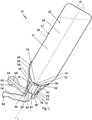
- FIG. 1 shown first embodiment according to a erfindugnsgefflessen nose shower 10 is shown in the use position (overhead position), ie tilted by 180 °.
- the nasal douche 10 has in the interior 11 of a separate container part 12 a rinsing liquid 14 and carries an independent cap member 24.
- the container part 12 and the cap member 24 are independent components which are fastened to each other by means of a screw 21 separable.
- the container part 12 may, depending on the application, for example, have a filling volume of about 100 ml to about 500 ml and is for example a bottle 12 'with a bottle bottom 16 and a subsequent to a bottle belly 18 tapered bottle neck 20th
- the maximum filling volume of the container part 12 depends, among other things, on the practical handling of the inventive nasal douche 10, i. the filling volume should not be so high that the user can only hold the nasal douche 10 with one hand with difficulty.
- the container part 12 may be a well-known bottle or any type of container part 12, which is capable of receiving the rinsing liquid 14 in its interior 11.
- an external thread 22 is attached to the outside of the bottle neck 20.
- the container part 12 may be made of a hard material as well as an elastic material.
- the material properties of the container part 12 have no influence on the functionality of the inventive nasal douche 10. This in contrast to the known nasal douche, as stated in the introduction, in which the container must be made elastic to produce a higher pressure by a manual compression of the container ,
- the independent cap member 24 is provided for the screw 21 with an internal thread 26, and according to Fig. 1 shown screwed onto the external thread 22 of the container part 12.
- cap portion 24 it is also possible for the cap portion 24 to have an internal thread that is incompatible with conventional bottles, such as PET bottles, for example Container part with a corresponding external thread is to be used in the nasal douche.
- this preferably has a shell-like portion 28 and serves in the installed state as a mechanical support for the container part 12 in the region of the transition from the bottle belly 18 to the tapered bottle neck 20.
- the shell-like portion 28 is formed integrally with the cap member 24 in this case.
- the shell-like portion 28 is preferably at least one deep cutout 30 is introduced, which allows the user of the nasal douche 10, a valve 32 to wait for hygienic reasons.
- the valve 32 has an annular valve seat 34 integrally formed on the cap part 24 and a plate-shaped valve member 36 cooperating therewith.
- the annular valve seat 34 is formed by the free end of a coincident to the container axis longitudinal axis L coaxial indentation 38 of the cap portion 24 in the passage opening 40 of the bottle neck 20.
- the indentation 38 is hollow cylindrical and forms a receptacle 42 for a tubular, angled mouthpiece 44 , Between the outer side 46 of the hollow cylindrical indentation 38 and the inner side 48 of the hollow cylindrical neck 20, a tubular passage 50 for the rinsing liquid 14 results.
- the indentation 38 of the cap portion 24 is opened to the bottom of the bottle 16 and forms the annular valve seat 24.
- the indentation 38 has adjacent to the valve seat 24 a web 52 radially inwardly with a centrally disposed to the valve seat 24, spherical thickened head 54 up.
- the valve member 36 is formed like a membrane and elastically deformable and has a through hole 56 centrally.
- valve member 36 with the through hole 56 can be pulled over the head 54 and in the assembled state, the elastically formed valve member 36 engages the head 54.
- the valve member 36 is biased against the valve seat 34, since the rear handle with respect Valve seat 24 is offset back. At rest, the valve member 36, i. when the valve 32 is closed, the outflow of rinsing liquid 14 is prevented.
- the nose lug 62 is in the present embodiment in one piece to the cap member 24th formed and projects laterally, wherein the outflow channel 60 of the lug extension 62 and the annular passage 50 for the rinsing liquid 14 are fluidly connected.
- the outflow channel 60 of the nasal approach 62 terminates in the end-side outlet opening 64 of the nasal approach 62, wherein the outflow channel 60 is arranged angled in the present embodiment in the direction of the bottle bottom 16, so that the angle between the longitudinal axis L and the longitudinal adjustment of the nasal approach 62 is less than 90 ° ,
- outflow channel 60 is also parallel to the bottle bottom 16 and thus could be arranged at right angles to the longitudinal axis L of the container part 12.
- the container part 12 is asymmetrical or evenly symmetrical with respect to the longitudinal axis L, so that the outflow channel 60 could be arranged at an obtuse angle to the longitudinal axis L of the container part 12.
- a nasen butterer end portion 66 of the nasal prong 62 is formed olive-thickened and is adapted to a nostril of the user (see Fig. 2 ) to be set.
- the nose-side end portion 66 may be shaped differently depending on the anatomical shape of the nostril of the user to allow an optimal fit of the nose-side end portion 66 of the nose lug 62 with the nose of the user. It should be noted, inter alia, that in use of the nasal douche 10 no rinsing liquid 14 should escape between the nostril of the user and the nose-side end portion 66 of the nasal appendage 62 and accordingly a sufficient seal should be ensured.
- the nose lug 62 is preferably rigidly mounted relative to the container portion 12 to allow proper rinsing of the nose while preventing slippage of the nose-side end portion 66 of the nose lug 62 in the nose.
- the mouthpiece 44 is rotatably inserted in the hollow cylindrical receptacle 42 in the present embodiment.
- the mouthpiece 44 is intended to be taken by the user in the mouth to blow breathing air into the container part 12 for flushing the nose, wherein the valve 32 can be moved from the rest position to an open position in which the valve member 36 is lifted from the valve seat 34 is.
- the mouthpiece 44 has an elastic material, so that by bending the mouthpiece 44, different distances between the user's mouth and nose can be compensated for during use.
- the mouthpiece 44 is formed angled. However, it is also conceivable that the mouthpiece 44 is straight. In this case, the receptacle 42 for the mouthpiece 44 extends approximately radially.
- the nasal douche 10 according to the invention When the nasal douche 10 according to the invention is filled with rinsing liquid 14 and as in Fig. 1 shown closed by the cap member 24 and tilted by 180 ° (ie in the overhead position), the hydrostatic pressure of the rinsing liquid 14 acts on the plate-shaped valve member 36 of the valve 32, so that no rinsing fluid 14 from the container part 12 in a Einblas Kunststoffkanal 68 of the mouthpiece 44 arrive can. Because of the constricted bottle neck 20 and the narrowed hollow cylindrical passage 50 via the outflow channel 60 to the outlet opening 64, no ambient air can enter the container via the nose extension 62 from the outside, so that the rinsing liquid 14 can not reach the outlet opening from the container part 12. In order to allow the rinsing liquid 14 to flow out of the container part 12, a pressure difference must be produced in the container part 12.
- the applied breathing pressure must first overcome the closing force of the valve member 36.
- the breathing air pressure must be greater than the sum of the closing force of the valve member 36 itself plus the hydrostatic pressure of the rinsing liquid 14, so that the valve member 36 can lift off the valve seat 34 to bring breathing air into the container part 12 and so a pressure difference in the To produce container part 12.
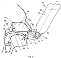
- the soft palate 76 of the user lays close to a back wall 78 of the pharynx and thus separates a nasal cavity 80 from an oropharynx 88.
- the nasal cavity 80 is formed by a left nasal cavity 82 and a right nasal cavity 86, which are spatially separated by a nasal septum 84 and pass behind the nasal septum 84 into a common nasopharynx 81.
- the rinsing fluid 14 from the inventive nasal shower 10 when blowing the breathing air through the mouthpiece 44 into the container part 12, exclusively through the nasal cavity 80 and the other nostril 92 drain and not, as in known nasal douche, down into the oropharynx 88 arrive.
- the flushing liquid 14 flows upon application of the valve 32 with breathing air from the mouthpiece 44 and overcoming the closing force of the valve member 36 from the container part 12 through the passage 50 and the outflow channel 60 to the outlet opening 64 of the nasal approach 62 and from there via the (here) left nostril 92 in the (here) left nasal cavity 86, there to the trailing edge 90 of the nasal septum 84 and then in reverse flow through the (here) right nasal cavity 82 to (here) right nostril 70, where the rinsing fluid 14 then exits again. Swallowing the rinsing liquid 14 is thus no longer possible with the nasal douche 10 according to the invention, since the soft palate 78 completely closes the way to the oropharyngeal cavity 88.
- the soft palate 76 releases the path from the nose room 80 into the oropharynx 88, but closes the valve 32, whereby the outflow of further rinsing fluid 14 is interrupted.
- the cap member 24 is anatomically shaped so that the nasal douche 10 with a hand can be held and is positioned on the first nostril 70, that due to the hydrostatic pressure on the rinsing liquid 14 and the valve member 36 premature leakage of the rinsing liquid 14 is prevented from the container part 12.
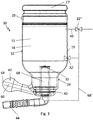
- the container part 12 is formed integrally with the cap part 24. It will be the same reference numerals as in connection with Fig. 1 and Fig. 2 used.
- a refill opening 25 in the container part 12 is provided for filling the container part 12 with rinsing liquid 14, which can be closed by means of a lid 27.
- valve 32 is associated with the cap member 24 in the same manner and also the mouthpiece 44 is inserted in the same manner in the receptacle 42 of the cap member 24, as in connection with Fig. 1 explained in detail.
- valve 32 is closed in the rest position, so that the drainage of flushing liquid 14 is prevented from the container part 12 in the direction of the outlet opening 64 and the valve 32 is by applying breathable air, in which the user blows into the mouthpiece 44 breathing air in the open position be brought so that in the open position of the valve 32 breathing air enters the container part 12, whereby the drainage of rinsing liquid 14 is released from the container part 12 in the direction of the outlet opening 64.
- the mouthpiece 44 can also be connected via a hose connection 68 '(shown in dashed lines) directly to a valve 32' attached to an outer wall 19 of the container part 12, as in FIG Fig. 3 indicated by dashed lines.
- the valve 32 ' is inserted in an opening in the outer wall 19 of the container part 12, with the same functional effect as in connection with Fig. 2 described in detail.
- the open position of the valve 32 ' also breathing air from the mouthpiece 44 passes into the container part 12 and so the drainage of rinsing liquid 14 is released from the container part 12 in the direction of the outlet opening 64.
- valve 32 '' as in Fig. 3 , also shown by dashed lines, is located in an inlet channel 69, wherein the valve 32 '' in the rest position prevents access of ambient air into the interior 11 of the container part 12 and upon exposure of the valve 32 '' with breathing air by the user in the mouthpiece 44th Breathing air blows into the open position can be brought, so that in the open position of the valve 32 '' ambient air enters the container part 12, whereby the flow of rinsing fluid 14 is released from the container part 12 in the direction of the outlet opening 64.
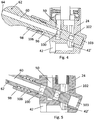
- the nose lug 62 is not integrally formed with the cap member 24, but is a separate, rectilinear one Part which is slidably mounted in a blind-hole-shaped receptacle 96 in its longitudinal direction.
- the receptacle 96 is formed by the cap member 24 and an extension 98 integrally formed thereon.
- the extension 98 is angled in the direction against the bottom of the bottle 16.
- the outflow channel 60 is formed like a blind hole, wherein at the closed end of the outflow channel 60 inside, crosswise radial first passages 100 are connected by the nose extension 62 with the outflow channel 60.
- radial second passages 102 which are separated from the outflow channel 60, are recessed crosswise.
- the nose lug 62 closes a connection channel 42 'between the receptacle 42 of the cap part 24 for the mouthpiece 44 and the container part 12.
- the lug extension 62 is attached to the one nostril 70 and by pressing the cap member 24 in the direction against the nose of the lug extension 62 is moved against the force of the spring 106 in the direction of the cap member 24 until the nose lug 62 abuts the bottom 103 of the receptacle 96, as this Fig. 4 shows.
- a supply hole guides the cap portion 24 to the bottom 103 of the receptacle 96.
- flushing liquid 14 exits through the first passages 100 and the outflow channel 60 and thus reaches the nose of the user.
- Fig. 6 combined with Fig. 7 shows another embodiment of the present invention, wherein the valve 108 closes the outflow channel 60 in the nasal approach 62 and releases when exposed to breathing air.
- the lug extension 62 has a passage 110 transversely to the outflow channel 60 as a valve seat 112.
- the valve seat 112 cooperates with a valve pin 118 formed as a closure pin 114 and cooperating with an actuator 116.
- the actuator 116 Upon application of a blow-in space 119 between the actuator 116 and the mouthpiece 44 with breathing air from the mouthpiece 44, as in Fig. 8 combined with Fig. 9 1, the actuator 116 displaces the closure pin 114 such that a passage 120 in the form of a circumferential groove in the closure pin 114 releases the outflow channel 60.
- the actuator 116 preferably has a rubber-elastic membrane 122, which depends on the breathing air in the injection space 119, as in Fig. 9 shown, or as shown in Fig. 7 shown again to move the locking pin 114 in the passage 110 back and forth accordingly.
- connection channel (not shown) with a smaller cross section than the outflow channel 60 to the interior 11 of the container part 12 to guide the breathing air in the open position of the valve 108 from the mouthpiece 44 into the container part 12.
- the connecting channel of the container part 12 has a ventilation opening 124 and is provided with a check valve 126, which prevents the escape of rinsing fluid 14 from the container part 12 through the ventilation opening 124 and the influx of ambient air through the ventilation opening 124 in allows the container part 12, so that in the open position of the valve 108, the ambient air flowing into the container part 12 allows the flushing liquid 14 to flow out in the direction of the outflow channel 60.
Landscapes
- Health & Medical Sciences (AREA)
- Engineering & Computer Science (AREA)
- Life Sciences & Earth Sciences (AREA)
- Veterinary Medicine (AREA)
- Public Health (AREA)
- General Health & Medical Sciences (AREA)
- Animal Behavior & Ethology (AREA)
- Heart & Thoracic Surgery (AREA)
- Hematology (AREA)
- Biomedical Technology (AREA)
- Anesthesiology (AREA)
- General Engineering & Computer Science (AREA)
- Mechanical Engineering (AREA)
- Physical Education & Sports Medicine (AREA)
- Epidemiology (AREA)
- Pain & Pain Management (AREA)
- Otolaryngology (AREA)
- Rehabilitation Therapy (AREA)
- Physics & Mathematics (AREA)
- Fluid Mechanics (AREA)
- Bioinformatics & Cheminformatics (AREA)
- Pulmonology (AREA)
- Devices For Medical Bathing And Washing (AREA)
- Infusion, Injection, And Reservoir Apparatuses (AREA)
Claims (15)
- Douche nasale présentant:une partie de conteneur (12) et une partie de capuchon (24), la partie de conteneur (12) servant à recevoir un liquide de rinçage (14) et portant la partie de capuchon (24);un embout nasal (62) de la partie de capuchon (24) avec une ouverture de sortie (64) pour le liquide de rinçage (14) reliée pour l'écoulement avec un intérieur (11) de la partie de conteneur (12) au moyen d'un canal d'écoulement (60), l'embout nasal (62) étant prévu pour être appliqué à une narine (70, 92) de l'utilisateur; etune valve (32, 32', 32", 108);caractérisée en ce que
un embout buccal (44) pour la commande de la valve (32, 32', 32", 108) est associé à la partie de conteneur (12) ou à la partie de capuchon (24);
la valve (32, 32', 32", 108) est fermée dans une position de repos et ce faisant l'écoulement de liquide de rinçage (14) à travers l'embout nasal (62) est empêchée; et
la valve (32, 32', 32", 108) peut être amenée dans une position ouverte par activation par de l'air respiré quand l'utilisateur souffle de l'air respiré à travers l'embout buccal (44) et ce faisant du liquide de rinçage (14) s'écoule à travers l'embout nasal (62), de l'air respiré ou de l'air ambiant affluant dans la partie de conteneur (12) pour l'écoulement. - Douche nasale selon la revendication 1, caractérisée en ce que la partie de conteneur (12) est façonnée comme un composant indépendant et la partie de capuchon (24) est façonnée comme un composant indépendant, et celles-ci sont fixées l'une à l'autre, préférablement de façon séparable.
- Douche nasale selon la revendication 2, caractérisée en ce que la partie de capuchon (24) et la partie de conteneur (12) sont fixées l'une à l'autre au moyen d'un assemblage à vis ou d'une fermeture à baïonnette.
- Douche nasale selon la revendication 2, caractérisée en ce que la partie de capuchon (24) et la partie de conteneur (12) sont fixées l'une à l'autre au moyen d'un ajustage serré.
- Douche nasale selon la revendication 1, caractérisée en ce que la partie de conteneur (12) est façonnée en une pièce avec la partie de capuchon (24).
- Douche nasale selon la revendication 5, caractérisée en ce que la partie de conteneur (12) présente une ouverture de rechargement (25) qui peut être fermée au moyen d'un couvercle (27).
- Douche nasale selon l'une des revendications 1 à 6, caractérisée en ce que la valve (32, 32', 32"), dans la position de repos, ferme un canal d'insufflation d'air (68, 68') menant de l'embout buccal (44) à la partie de conteneur (12), ce qui fait qu'il n'y a pas d'air respiré ou d'air ambiant qui arrive dans la partie de conteneur (12) et que l'écoulement de liquide de rinçage (14) de la partie de conteneur (12) dans la direction de l'ouverture de sortie (64) est empêchée, et la valve (32, 32', 32") peut être amenée dans une position ouverte par activation par de l'air respiré de telle sorte que l'air respiré arrive dans la partie de conteneur (12) au moyen du canal d'insufflation d'air (68, 68') ou de l'air ambiant arrive dans la partie de conteneur (12) et le liquide de rinçage (14) peut s'écouler de la partie de conteneur (12) dans la direction de l'ouverture de sortie (64).
- Douche nasale selon l'une des revendications 1 à 7, caractérisée en ce que la valve (32) présente un siège de valve (34), préférablement façonné sur la partie de capuchon (24) et préférablement en forme d'anneau, et un organe de valve (36), préférablement en forme d'assiette, interagissant avec celui-ci.
- Douche nasale selon la revendication 8, caractérisée par une traverse (52) avec une tête (54) épaissie préférablement au moins approximativement en forme d'oeuf ou en forme de sphère, l'organe de valve (36) étant ajusté au siège de valve (34), préférablement sous précontrainte, étant façonné en forme de membrane et déformable de façon élastique, présentant un trou de passage (56) central, pouvant être tiré au-dessus de la tête (54) avec le trou de passage (56) lors du montage et venant en prise derrière la tête (54) dans l'état monté.
- Douche nasale selon l'une des revendications 1 à 9, caractérisée en ce que l'embout buccal (44) disposé sur la partie de capuchon (24) présente un matériau élastique de telle sorte que différentes distances entre la bouche et le nez de l'utilisateur sont compensables lors de l'utilisation.
- Douche nasale selon l'une des revendications 1 à 10, caractérisée en ce que l'embout buccal (44) est interchangeable et préférablement disponible avec différentes dimensions pour des groupes d'utilisateurs de physiognomie différente.
- Douche nasale selon l'une des revendications 1 à 11, caractérisée en ce que l'embout buccal (44) est emboîtable de façon interchangeable dans un réceptacle (42) de la partie de capuchon (24) ou peut être enfilé sur un embout de la partie de capuchon (24), l'embout buccal (44) étant préférablement façonné droit ou plié.
- Douche nasale selon la revendication 1, caractérisée en ce que la valve (108) ferme le canal d'écoulement (60) dans la position de repos et libère le canal d'écoulement (60) dans la position ouverte.
- Douche nasale selon la revendication 13, caractérisée en ce que la valve (108) présente un passage (110) en travers le canal d'écoulement (60) comme siège de valve (112), lequel interagit avec un organe de valve, qui est façonné comme une tige de fermeture (114) et interagit avec un organe d'actionnement (116), de telle sorte que, dans la position de repos, la tige de fermeture (114) ferme le canal d'écoulement (60) et, dans la position ouverte, l'organe d'actionnement (116) déplace la tige de fermeture (114) lors de l'activation par de l'air respiré de telle sorte que le passage (120) libère le canal d'écoulement (60).
- Douche nasale selon la revendication 13 ou 14, caractérisée en ce que la partie de conteneur (12) présente une ouverture de ventilation (124) et est préférablement munie d'une valve de retenue (126) qui empêche la sortie de liquide de rinçage (14) de la partie de conteneur (12) à travers l'ouverture de ventilation (124) et permet l'afflux d'air ambiant à travers l'ouverture de ventilation (124) dans la partie de conteneur (12).
Priority Applications (6)
| Application Number | Priority Date | Filing Date | Title |
|---|---|---|---|
| EP13005214.5A EP2868334B1 (fr) | 2013-11-05 | 2013-11-05 | Douche nasale |
| JP2016550947A JP6659556B2 (ja) | 2013-11-05 | 2014-09-06 | 呼吸気により起動され得るバルブを備えた鼻洗浄器 |
| PCT/EP2014/002423 WO2015067332A1 (fr) | 2013-11-05 | 2014-09-06 | Douche nasale avec valve pouvant être actionnée par l'air respiratoire |
| US15/034,771 US10076602B2 (en) | 2013-11-05 | 2014-09-06 | Nasal douche with valve that can be actuated by respiratory air |
| CA2929327A CA2929327C (fr) | 2013-11-05 | 2014-09-06 | Douche nasale avec valve pouvant etre actionnee par l'air respiratoire |
| CN201480060369.XA CN105873625B (zh) | 2013-11-05 | 2014-09-06 | 具有可由呼吸空气致动的阀的鼻腔清洗器 |
Applications Claiming Priority (1)
| Application Number | Priority Date | Filing Date | Title |
|---|---|---|---|
| EP13005214.5A EP2868334B1 (fr) | 2013-11-05 | 2013-11-05 | Douche nasale |
Publications (2)
| Publication Number | Publication Date |
|---|---|
| EP2868334A1 EP2868334A1 (fr) | 2015-05-06 |
| EP2868334B1 true EP2868334B1 (fr) | 2017-01-11 |
Family
ID=49553984
Family Applications (1)
| Application Number | Title | Priority Date | Filing Date |
|---|---|---|---|
| EP13005214.5A Active EP2868334B1 (fr) | 2013-11-05 | 2013-11-05 | Douche nasale |
Country Status (6)
| Country | Link |
|---|---|
| US (1) | US10076602B2 (fr) |
| EP (1) | EP2868334B1 (fr) |
| JP (1) | JP6659556B2 (fr) |
| CN (1) | CN105873625B (fr) |
| CA (1) | CA2929327C (fr) |
| WO (1) | WO2015067332A1 (fr) |
Families Citing this family (9)
| Publication number | Priority date | Publication date | Assignee | Title |
|---|---|---|---|---|
| US9884148B2 (en) * | 2014-05-30 | 2018-02-06 | Neilmed Pharmaceuticals, Inc. | Angular cap for dispensing liquids |
| EP3412325B1 (fr) | 2017-06-08 | 2019-09-25 | Aptar Radolfzell GmbH | Tête distributrice pour l'application nasale de liquide provenant d'un accumulateur de pression |
| USD872852S1 (en) * | 2017-08-11 | 2020-01-14 | Rhinoclear Nasal Care Solutions Inc. | Nasal irrigation apparatus |
| CN111920382A (zh) * | 2018-08-17 | 2020-11-13 | 毛金霞 | 一种妇产科综合检查仪 |
| CN109745222B (zh) * | 2019-02-28 | 2023-08-29 | 广州美术学院 | 便携式洗鼻器 |
| CN109939326B (zh) * | 2019-04-18 | 2023-10-31 | 首都医科大学附属北京安贞医院 | 基于呼气压力的嗅觉训练装置 |
| USD944391S1 (en) * | 2020-05-01 | 2022-02-22 | Gurunanda, Llc | Nasal wash bottle |
| WO2023165486A1 (fr) * | 2022-03-01 | 2023-09-07 | 园丁医疗科技(苏州)有限公司 | Irrigateur nasal électrique à détection d'expiration buccale |
| USD1006983S1 (en) * | 2023-03-13 | 2023-12-05 | ChongQing Moffy Innovation Technology Co., Ltd. | Nasal irrigator nozzle |
Family Cites Families (46)
| Publication number | Priority date | Publication date | Assignee | Title |
|---|---|---|---|---|
| GB178630A (en) * | 1921-02-15 | 1922-04-27 | Ramsay Middleton Winter | An improved nasal irrigator |
| DE29800680U1 (de) * | 1998-01-19 | 1998-05-20 | Schmidt, Thomas, Prof. Dr., 30853 Langenhagen | Nasenspülkanne |
| AU766410B2 (en) * | 1999-03-03 | 2003-10-16 | Optinose As | Nasal delivery device |
| GB0015309D0 (en) | 2000-06-21 | 2000-08-16 | Djupesland Per G | Apparatus |
| DE10151676A1 (de) * | 2001-10-19 | 2003-05-08 | Siemens & Co Quellenprodukte | Nasendusche |
| GB0207422D0 (en) | 2002-03-28 | 2002-05-08 | Optinose As | Nasal devices |
| GB0209494D0 (en) | 2002-04-25 | 2002-06-05 | Optinose As | Nasal devices |
| GB0215270D0 (en) | 2002-07-02 | 2002-08-14 | Optinose As | Nasal devices |
| GB0215904D0 (en) | 2002-07-09 | 2002-08-21 | Team Holdings Uk Ltd | Drug delivery system and method |
| GB0311570D0 (en) | 2003-05-20 | 2003-06-25 | Optinose As | Delivery device and method |
| GB0319119D0 (en) | 2003-08-14 | 2003-09-17 | Optinose As | Delivery devices |
| GB0320171D0 (en) | 2003-08-28 | 2003-10-01 | Optinose As | Delivery devices |
| USD530815S1 (en) | 2004-03-19 | 2006-10-24 | Optinose As | Nasal delivery device |
| GB0420513D0 (en) | 2004-09-15 | 2004-10-20 | Optinose As | Powder delivery devices |
| GB0503738D0 (en) | 2005-02-23 | 2005-03-30 | Optinose As | Powder delivery devices |
| DE102005035130A1 (de) | 2005-07-26 | 2007-02-01 | Siemens & Co. Heilwasser Und Quellenprodukte Des Staatsbades Bad Ems Gmbh & Co. Kg | Nasendusche |
| US10478574B2 (en) | 2006-01-19 | 2019-11-19 | Optinose As | Nasal administration |
| SI1810598T1 (sl) * | 2006-01-24 | 2010-02-26 | Rhea Vendors Spa | Naprava in postopek za nadzor avtomatov za distribucijo pijač |
| WO2007093784A1 (fr) | 2006-02-14 | 2007-08-23 | Optinose As | Dispositif et procede d'administration |
| GB0604319D0 (en) | 2006-03-03 | 2006-04-12 | Optinose As | Nasal delivery |
| GB0604444D0 (en) | 2006-03-06 | 2006-04-12 | Optinose As | Nasal devices |
| GB0605799D0 (en) | 2006-03-23 | 2006-05-03 | Optinose As | Nasal delivery devices |
| GB2437488A (en) | 2006-04-25 | 2007-10-31 | Optinose As | Pharmaceutical oily formulation for nasal or buccal administration |
| GB2438834A (en) | 2006-06-08 | 2007-12-12 | Optinose As | Intranasal protein administration |
| GB2440316A (en) | 2006-07-25 | 2008-01-30 | Optinose As | Nasal inhaler with scrubber |
| CN200970340Y (zh) * | 2006-11-16 | 2007-11-07 | 刘红伟 | 鼻腔清洗器 |
| GB0623732D0 (en) | 2006-11-28 | 2007-01-10 | Optinose As | Powder delivery devices |
| GB0623731D0 (en) | 2006-11-28 | 2007-01-10 | Optinose As | Delivery device |
| GB0623728D0 (en) | 2006-11-28 | 2007-01-10 | Optinose As | Delivery devices |
| GB2448183A (en) | 2007-04-05 | 2008-10-08 | Optinose As | Nasal powder delivery device |
| GB2448193A (en) | 2007-04-05 | 2008-10-08 | Optinose As | Nasal delivery device |
| DE202007012817U1 (de) | 2007-09-13 | 2007-12-20 | Siemens & Co. Heilwasser Und Quellenprodukte Des Staatsbades Bad Ems Gmbh & Co. Kg | Rückschlagventil für eine Nasendusche |
| GB0719299D0 (en) | 2007-10-03 | 2007-11-14 | Optinose As | Nasal delivery devices |
| US20110318345A1 (en) | 2008-09-15 | 2011-12-29 | Optinose As | Nasal delivery |
| JP2012525209A (ja) * | 2009-04-27 | 2012-10-22 | アードバーク メディカル, エルエルシー | 洗浄および吸引の装置および方法 |
| CN202061057U (zh) * | 2010-02-05 | 2011-12-07 | 上海易化生国际贸易有限公司 | 瓶子 |
| GB201015371D0 (en) | 2010-09-14 | 2010-10-27 | Optinose As | Nasal delivery |
| US9949923B2 (en) | 2011-03-15 | 2018-04-24 | Optinose As | Nasal delivery |
| KR20110056462A (ko) * | 2011-04-22 | 2011-05-30 | 김현수 | 코세정 분무 장치 |
| EP3281664B8 (fr) | 2012-02-24 | 2020-12-30 | Optinose AS | Dispositifs d'administration nasale |
| DK2817054T3 (da) | 2012-02-24 | 2020-03-02 | Optinose As | Indretning til nasal afgivelse |
| MX358062B (es) | 2012-02-24 | 2018-08-03 | Optinose As | Dispositivos de suministro nasal. |
| KR102345816B1 (ko) | 2013-03-26 | 2021-12-30 | 옵티노즈 에이에스 | 코 투여 |
| USD761951S1 (en) | 2013-05-23 | 2016-07-19 | Optinose As | Nosepiece unit |
| USD725769S1 (en) | 2013-05-23 | 2015-03-31 | Optinose As | Nasal delivery device |
| USD723156S1 (en) | 2013-05-23 | 2015-02-24 | Optinose As | Nasal delivery device |
-
2013
- 2013-11-05 EP EP13005214.5A patent/EP2868334B1/fr active Active
-
2014
- 2014-09-06 CN CN201480060369.XA patent/CN105873625B/zh active Active
- 2014-09-06 WO PCT/EP2014/002423 patent/WO2015067332A1/fr active Application Filing
- 2014-09-06 US US15/034,771 patent/US10076602B2/en active Active
- 2014-09-06 CA CA2929327A patent/CA2929327C/fr active Active
- 2014-09-06 JP JP2016550947A patent/JP6659556B2/ja active Active
Also Published As
| Publication number | Publication date |
|---|---|
| CN105873625A (zh) | 2016-08-17 |
| US20160263307A1 (en) | 2016-09-15 |
| CA2929327C (fr) | 2022-11-08 |
| US10076602B2 (en) | 2018-09-18 |
| JP6659556B2 (ja) | 2020-03-04 |
| CA2929327A1 (fr) | 2015-05-14 |
| CN105873625B (zh) | 2019-03-15 |
| JP2016538976A (ja) | 2016-12-15 |
| EP2868334A1 (fr) | 2015-05-06 |
| WO2015067332A1 (fr) | 2015-05-14 |
Similar Documents
| Publication | Publication Date | Title |
|---|---|---|
| EP2868334B1 (fr) | Douche nasale | |
| DE69820189T2 (de) | System und Verfahren für Sprüh- oder Aerosolspitze mit Einweg-Strömung | |
| EP1620155B1 (fr) | Ensemble raccord de nebuliseur pour appareils respiratoires ou analogues | |
| EP2908895B1 (fr) | Valve de phonation destinée à une canule de trachéotomie | |
| DE60111226T2 (de) | Verteilerventil für ein nasenspray | |
| EP0088871B1 (fr) | Soupape pour cathéter | |
| DE10126807A1 (de) | Inhalationstherapiegerät mit einem Ventil zur Begrenzung des Inspirationsflusses | |
| DE2908978A1 (de) | Ventilsystem fuer beatmungsgeraete | |
| EP2446177B1 (fr) | Vanne à membrane | |
| EP2236213A2 (fr) | Dispositif de sortie | |
| CH706616A2 (de) | Larynxmaske mit einem supraglottischen Tubus. | |
| EP0985454B1 (fr) | Distributeur de fluide | |
| DE102012111281A1 (de) | Verdampferfülleinrichtung und Verfahren zum Füllen eines Verdampfers | |
| WO2018224206A1 (fr) | Tête de diffusion pour l'application nasale d'un liquide à partir d'un accumulateur de pression | |
| EP3427839A1 (fr) | Distributeur de liquide ayant une bouteille ventilée et une tête de distribution associée | |
| DE102016212892C5 (de) | Pumpkopf sowie Dosiervorrichtung | |
| EP2805748B1 (fr) | Masque respiratoire doté d'une soupape de respiration de secours | |
| WO2016059179A1 (fr) | Valve, équipement de sport gonflable pourvu d'une valve et pompe | |
| EP2065100A1 (fr) | Dispositif de pulvérisation d'agent séparateur pour une machine de coulée | |
| EP3624883B1 (fr) | Soupape d'expiration d'un dispositif respiratoire avec résistance à l'écoulement minimisant les bruits | |
| DE29721766U1 (de) | Anschlußstück für die Atemgasversorgung eines Patienten | |
| WO2006131002A1 (fr) | Systeme de fermeture pour gourde | |
| EP2428244B1 (fr) | Masque respiratoire | |
| EP3023752A1 (fr) | Distributeur de liquide et tête distributrice correspondante | |
| EP3318296B1 (fr) | Soupape d'expiration |
Legal Events
| Date | Code | Title | Description |
|---|---|---|---|
| PUAI | Public reference made under article 153(3) epc to a published international application that has entered the european phase |
Free format text: ORIGINAL CODE: 0009012 |
|
| 17P | Request for examination filed |
Effective date: 20131105 |
|
| AK | Designated contracting states |
Kind code of ref document: A1 Designated state(s): AL AT BE BG CH CY CZ DE DK EE ES FI FR GB GR HR HU IE IS IT LI LT LU LV MC MK MT NL NO PL PT RO RS SE SI SK SM TR |
|
| AX | Request for extension of the european patent |
Extension state: BA ME |
|
| RBV | Designated contracting states (corrected) |
Designated state(s): AL AT BE BG CH CY CZ DE DK EE ES FI FR GB GR HR HU IE IS IT LI LT LU LV MC MK MT NL NO PL PT RO RS SE SI SK SM TR |
|
| R17P | Request for examination filed (corrected) |
Effective date: 20151028 |
|
| GRAP | Despatch of communication of intention to grant a patent |
Free format text: ORIGINAL CODE: EPIDOSNIGR1 |
|
| INTG | Intention to grant announced |
Effective date: 20160601 |
|
| GRAS | Grant fee paid |
Free format text: ORIGINAL CODE: EPIDOSNIGR3 |
|
| GRAA | (expected) grant |
Free format text: ORIGINAL CODE: 0009210 |
|
| STAA | Information on the status of an ep patent application or granted ep patent |
Free format text: STATUS: THE PATENT HAS BEEN GRANTED |
|
| AK | Designated contracting states |
Kind code of ref document: B1 Designated state(s): AL AT BE BG CH CY CZ DE DK EE ES FI FR GB GR HR HU IE IS IT LI LT LU LV MC MK MT NL NO PL PT RO RS SE SI SK SM TR |
|
| REG | Reference to a national code |
Ref country code: GB Ref legal event code: FG4D Free format text: NOT ENGLISH |
|
| REG | Reference to a national code |
Ref country code: CH Ref legal event code: EP |
|
| REG | Reference to a national code |
Ref country code: AT Ref legal event code: REF Ref document number: 860684 Country of ref document: AT Kind code of ref document: T Effective date: 20170115 |
|
| REG | Reference to a national code |
Ref country code: IE Ref legal event code: FG4D Free format text: LANGUAGE OF EP DOCUMENT: GERMAN |
|
| REG | Reference to a national code |
Ref country code: DE Ref legal event code: R096 Ref document number: 502013006030 Country of ref document: DE |
|
| REG | Reference to a national code |
Ref country code: LT Ref legal event code: MG4D |
|
| REG | Reference to a national code |
Ref country code: NL Ref legal event code: MP Effective date: 20170111 |
|
| PG25 | Lapsed in a contracting state [announced via postgrant information from national office to epo] |
Ref country code: NL Free format text: LAPSE BECAUSE OF FAILURE TO SUBMIT A TRANSLATION OF THE DESCRIPTION OR TO PAY THE FEE WITHIN THE PRESCRIBED TIME-LIMIT Effective date: 20170111 |
|
| PG25 | Lapsed in a contracting state [announced via postgrant information from national office to epo] |
Ref country code: NO Free format text: LAPSE BECAUSE OF FAILURE TO SUBMIT A TRANSLATION OF THE DESCRIPTION OR TO PAY THE FEE WITHIN THE PRESCRIBED TIME-LIMIT Effective date: 20170411 Ref country code: LT Free format text: LAPSE BECAUSE OF FAILURE TO SUBMIT A TRANSLATION OF THE DESCRIPTION OR TO PAY THE FEE WITHIN THE PRESCRIBED TIME-LIMIT Effective date: 20170111 Ref country code: HR Free format text: LAPSE BECAUSE OF FAILURE TO SUBMIT A TRANSLATION OF THE DESCRIPTION OR TO PAY THE FEE WITHIN THE PRESCRIBED TIME-LIMIT Effective date: 20170111 Ref country code: FI Free format text: LAPSE BECAUSE OF FAILURE TO SUBMIT A TRANSLATION OF THE DESCRIPTION OR TO PAY THE FEE WITHIN THE PRESCRIBED TIME-LIMIT Effective date: 20170111 Ref country code: GR Free format text: LAPSE BECAUSE OF FAILURE TO SUBMIT A TRANSLATION OF THE DESCRIPTION OR TO PAY THE FEE WITHIN THE PRESCRIBED TIME-LIMIT Effective date: 20170412 Ref country code: IS Free format text: LAPSE BECAUSE OF FAILURE TO SUBMIT A TRANSLATION OF THE DESCRIPTION OR TO PAY THE FEE WITHIN THE PRESCRIBED TIME-LIMIT Effective date: 20170511 |
|
| PG25 | Lapsed in a contracting state [announced via postgrant information from national office to epo] |
Ref country code: SE Free format text: LAPSE BECAUSE OF FAILURE TO SUBMIT A TRANSLATION OF THE DESCRIPTION OR TO PAY THE FEE WITHIN THE PRESCRIBED TIME-LIMIT Effective date: 20170111 Ref country code: PL Free format text: LAPSE BECAUSE OF FAILURE TO SUBMIT A TRANSLATION OF THE DESCRIPTION OR TO PAY THE FEE WITHIN THE PRESCRIBED TIME-LIMIT Effective date: 20170111 Ref country code: PT Free format text: LAPSE BECAUSE OF FAILURE TO SUBMIT A TRANSLATION OF THE DESCRIPTION OR TO PAY THE FEE WITHIN THE PRESCRIBED TIME-LIMIT Effective date: 20170511 Ref country code: BG Free format text: LAPSE BECAUSE OF FAILURE TO SUBMIT A TRANSLATION OF THE DESCRIPTION OR TO PAY THE FEE WITHIN THE PRESCRIBED TIME-LIMIT Effective date: 20170411 Ref country code: ES Free format text: LAPSE BECAUSE OF FAILURE TO SUBMIT A TRANSLATION OF THE DESCRIPTION OR TO PAY THE FEE WITHIN THE PRESCRIBED TIME-LIMIT Effective date: 20170111 Ref country code: LV Free format text: LAPSE BECAUSE OF FAILURE TO SUBMIT A TRANSLATION OF THE DESCRIPTION OR TO PAY THE FEE WITHIN THE PRESCRIBED TIME-LIMIT Effective date: 20170111 Ref country code: RS Free format text: LAPSE BECAUSE OF FAILURE TO SUBMIT A TRANSLATION OF THE DESCRIPTION OR TO PAY THE FEE WITHIN THE PRESCRIBED TIME-LIMIT Effective date: 20170111 |
|
| REG | Reference to a national code |
Ref country code: CH Ref legal event code: NV Representative=s name: PATENTANWAELTE SCHAAD, BALASS, MENZL AND PARTN, CH |
|
| REG | Reference to a national code |
Ref country code: DE Ref legal event code: R097 Ref document number: 502013006030 Country of ref document: DE |
|
| PG25 | Lapsed in a contracting state [announced via postgrant information from national office to epo] |
Ref country code: CZ Free format text: LAPSE BECAUSE OF FAILURE TO SUBMIT A TRANSLATION OF THE DESCRIPTION OR TO PAY THE FEE WITHIN THE PRESCRIBED TIME-LIMIT Effective date: 20170111 Ref country code: EE Free format text: LAPSE BECAUSE OF FAILURE TO SUBMIT A TRANSLATION OF THE DESCRIPTION OR TO PAY THE FEE WITHIN THE PRESCRIBED TIME-LIMIT Effective date: 20170111 Ref country code: SK Free format text: LAPSE BECAUSE OF FAILURE TO SUBMIT A TRANSLATION OF THE DESCRIPTION OR TO PAY THE FEE WITHIN THE PRESCRIBED TIME-LIMIT Effective date: 20170111 Ref country code: RO Free format text: LAPSE BECAUSE OF FAILURE TO SUBMIT A TRANSLATION OF THE DESCRIPTION OR TO PAY THE FEE WITHIN THE PRESCRIBED TIME-LIMIT Effective date: 20170111 Ref country code: IT Free format text: LAPSE BECAUSE OF FAILURE TO SUBMIT A TRANSLATION OF THE DESCRIPTION OR TO PAY THE FEE WITHIN THE PRESCRIBED TIME-LIMIT Effective date: 20170111 |
|
| PLBE | No opposition filed within time limit |
Free format text: ORIGINAL CODE: 0009261 |
|
| STAA | Information on the status of an ep patent application or granted ep patent |
Free format text: STATUS: NO OPPOSITION FILED WITHIN TIME LIMIT |
|
| REG | Reference to a national code |
Ref country code: FR Ref legal event code: PLFP Year of fee payment: 5 |
|
| PG25 | Lapsed in a contracting state [announced via postgrant information from national office to epo] |
Ref country code: DK Free format text: LAPSE BECAUSE OF FAILURE TO SUBMIT A TRANSLATION OF THE DESCRIPTION OR TO PAY THE FEE WITHIN THE PRESCRIBED TIME-LIMIT Effective date: 20170111 Ref country code: SM Free format text: LAPSE BECAUSE OF FAILURE TO SUBMIT A TRANSLATION OF THE DESCRIPTION OR TO PAY THE FEE WITHIN THE PRESCRIBED TIME-LIMIT Effective date: 20170111 |
|
| 26N | No opposition filed |
Effective date: 20171012 |
|
| PG25 | Lapsed in a contracting state [announced via postgrant information from national office to epo] |
Ref country code: SI Free format text: LAPSE BECAUSE OF FAILURE TO SUBMIT A TRANSLATION OF THE DESCRIPTION OR TO PAY THE FEE WITHIN THE PRESCRIBED TIME-LIMIT Effective date: 20170111 |
|
| PG25 | Lapsed in a contracting state [announced via postgrant information from national office to epo] |
Ref country code: MC Free format text: LAPSE BECAUSE OF FAILURE TO SUBMIT A TRANSLATION OF THE DESCRIPTION OR TO PAY THE FEE WITHIN THE PRESCRIBED TIME-LIMIT Effective date: 20170111 |
|
| PG25 | Lapsed in a contracting state [announced via postgrant information from national office to epo] |
Ref country code: LU Free format text: LAPSE BECAUSE OF NON-PAYMENT OF DUE FEES Effective date: 20171105 |
|
| REG | Reference to a national code |
Ref country code: BE Ref legal event code: MM Effective date: 20171130 |
|
| REG | Reference to a national code |
Ref country code: IE Ref legal event code: MM4A |
|
| PG25 | Lapsed in a contracting state [announced via postgrant information from national office to epo] |
Ref country code: MT Free format text: LAPSE BECAUSE OF FAILURE TO SUBMIT A TRANSLATION OF THE DESCRIPTION OR TO PAY THE FEE WITHIN THE PRESCRIBED TIME-LIMIT Effective date: 20170111 |
|
| PG25 | Lapsed in a contracting state [announced via postgrant information from national office to epo] |
Ref country code: IE Free format text: LAPSE BECAUSE OF NON-PAYMENT OF DUE FEES Effective date: 20171105 |
|
| PG25 | Lapsed in a contracting state [announced via postgrant information from national office to epo] |
Ref country code: BE Free format text: LAPSE BECAUSE OF NON-PAYMENT OF DUE FEES Effective date: 20171130 |
|
| PG25 | Lapsed in a contracting state [announced via postgrant information from national office to epo] |
Ref country code: HU Free format text: LAPSE BECAUSE OF FAILURE TO SUBMIT A TRANSLATION OF THE DESCRIPTION OR TO PAY THE FEE WITHIN THE PRESCRIBED TIME-LIMIT; INVALID AB INITIO Effective date: 20131105 |
|
| PG25 | Lapsed in a contracting state [announced via postgrant information from national office to epo] |
Ref country code: CY Free format text: LAPSE BECAUSE OF FAILURE TO SUBMIT A TRANSLATION OF THE DESCRIPTION OR TO PAY THE FEE WITHIN THE PRESCRIBED TIME-LIMIT Effective date: 20170111 |
|
| PG25 | Lapsed in a contracting state [announced via postgrant information from national office to epo] |
Ref country code: MK Free format text: LAPSE BECAUSE OF FAILURE TO SUBMIT A TRANSLATION OF THE DESCRIPTION OR TO PAY THE FEE WITHIN THE PRESCRIBED TIME-LIMIT Effective date: 20170111 |
|
| REG | Reference to a national code |
Ref country code: AT Ref legal event code: MM01 Ref document number: 860684 Country of ref document: AT Kind code of ref document: T Effective date: 20181105 |
|
| PG25 | Lapsed in a contracting state [announced via postgrant information from national office to epo] |
Ref country code: AT Free format text: LAPSE BECAUSE OF NON-PAYMENT OF DUE FEES Effective date: 20181105 |
|
| PG25 | Lapsed in a contracting state [announced via postgrant information from national office to epo] |
Ref country code: TR Free format text: LAPSE BECAUSE OF FAILURE TO SUBMIT A TRANSLATION OF THE DESCRIPTION OR TO PAY THE FEE WITHIN THE PRESCRIBED TIME-LIMIT Effective date: 20170111 |
|
| PG25 | Lapsed in a contracting state [announced via postgrant information from national office to epo] |
Ref country code: AL Free format text: LAPSE BECAUSE OF FAILURE TO SUBMIT A TRANSLATION OF THE DESCRIPTION OR TO PAY THE FEE WITHIN THE PRESCRIBED TIME-LIMIT Effective date: 20170111 |
|
| PGFP | Annual fee paid to national office [announced via postgrant information from national office to epo] |
Ref country code: GB Payment date: 20231123 Year of fee payment: 11 |
|
| PGFP | Annual fee paid to national office [announced via postgrant information from national office to epo] |
Ref country code: FR Payment date: 20231120 Year of fee payment: 11 Ref country code: DE Payment date: 20231121 Year of fee payment: 11 Ref country code: CH Payment date: 20231202 Year of fee payment: 11 |