EP3552585A1 - Hinged transcatheter prosthetic heart valve delivery system - Google Patents
Hinged transcatheter prosthetic heart valve delivery system Download PDFInfo
- Publication number
- EP3552585A1 EP3552585A1 EP19178780.3A EP19178780A EP3552585A1 EP 3552585 A1 EP3552585 A1 EP 3552585A1 EP 19178780 A EP19178780 A EP 19178780A EP 3552585 A1 EP3552585 A1 EP 3552585A1
- Authority
- EP
- European Patent Office
- Prior art keywords
- hinge
- hub
- delivery device
- segments
- heart valve
- Prior art date
- Legal status (The legal status is an assumption and is not a legal conclusion. Google has not performed a legal analysis and makes no representation as to the accuracy of the status listed.)
- Granted
Links
- 210000003709 heart valve Anatomy 0.000 title claims abstract description 74
- 239000002775 capsule Substances 0.000 claims description 37
- 230000008859 change Effects 0.000 claims description 7
- 230000000717 retained effect Effects 0.000 claims description 7
- 239000007787 solid Substances 0.000 claims description 6
- 230000002950 deficient Effects 0.000 claims description 5
- 239000007943 implant Substances 0.000 abstract 1
- 238000010276 construction Methods 0.000 description 21
- 238000000034 method Methods 0.000 description 15
- 210000004115 mitral valve Anatomy 0.000 description 12
- 210000002216 heart Anatomy 0.000 description 9
- 210000001519 tissue Anatomy 0.000 description 9
- 210000003484 anatomy Anatomy 0.000 description 7
- 210000005246 left atrium Anatomy 0.000 description 7
- 230000007246 mechanism Effects 0.000 description 7
- 210000001765 aortic valve Anatomy 0.000 description 6
- 239000000463 material Substances 0.000 description 6
- 229910052751 metal Inorganic materials 0.000 description 5
- 239000002184 metal Substances 0.000 description 5
- 210000000591 tricuspid valve Anatomy 0.000 description 5
- 238000013459 approach Methods 0.000 description 4
- 230000017531 blood circulation Effects 0.000 description 4
- 210000003157 atrial septum Anatomy 0.000 description 3
- 229920005570 flexible polymer Polymers 0.000 description 3
- 229920000642 polymer Polymers 0.000 description 3
- 210000003102 pulmonary valve Anatomy 0.000 description 3
- 230000004044 response Effects 0.000 description 3
- 230000007704 transition Effects 0.000 description 3
- 238000011144 upstream manufacturing Methods 0.000 description 3
- 210000005166 vasculature Anatomy 0.000 description 3
- 241000283690 Bos taurus Species 0.000 description 2
- 208000031481 Pathologic Constriction Diseases 0.000 description 2
- 239000004696 Poly ether ether ketone Substances 0.000 description 2
- 206010067171 Regurgitation Diseases 0.000 description 2
- 229910000831 Steel Inorganic materials 0.000 description 2
- 239000000853 adhesive Substances 0.000 description 2
- 230000001070 adhesive effect Effects 0.000 description 2
- 230000000712 assembly Effects 0.000 description 2
- 238000000429 assembly Methods 0.000 description 2
- JUPQTSLXMOCDHR-UHFFFAOYSA-N benzene-1,4-diol;bis(4-fluorophenyl)methanone Chemical compound OC1=CC=C(O)C=C1.C1=CC(F)=CC=C1C(=O)C1=CC=C(F)C=C1 JUPQTSLXMOCDHR-UHFFFAOYSA-N 0.000 description 2
- 230000000694 effects Effects 0.000 description 2
- 239000003292 glue Substances 0.000 description 2
- 238000002513 implantation Methods 0.000 description 2
- 210000003516 pericardium Anatomy 0.000 description 2
- 229920002530 polyetherether ketone Polymers 0.000 description 2
- 210000005245 right atrium Anatomy 0.000 description 2
- 239000010959 steel Substances 0.000 description 2
- 230000036262 stenosis Effects 0.000 description 2
- 208000037804 stenosis Diseases 0.000 description 2
- 238000002560 therapeutic procedure Methods 0.000 description 2
- 241000283073 Equus caballus Species 0.000 description 1
- 241001465754 Metazoa Species 0.000 description 1
- MWCLLHOVUTZFKS-UHFFFAOYSA-N Methyl cyanoacrylate Chemical compound COC(=O)C(=C)C#N MWCLLHOVUTZFKS-UHFFFAOYSA-N 0.000 description 1
- 210000002376 aorta thoracic Anatomy 0.000 description 1
- 210000001367 artery Anatomy 0.000 description 1
- 238000010009 beating Methods 0.000 description 1
- 238000005452 bending Methods 0.000 description 1
- 230000008901 benefit Effects 0.000 description 1
- 238000009954 braiding Methods 0.000 description 1
- 230000002612 cardiopulmonary effect Effects 0.000 description 1
- 238000007796 conventional method Methods 0.000 description 1
- 230000008878 coupling Effects 0.000 description 1
- 238000010168 coupling process Methods 0.000 description 1
- 238000005859 coupling reaction Methods 0.000 description 1
- 230000001419 dependent effect Effects 0.000 description 1
- 230000004064 dysfunction Effects 0.000 description 1
- 210000001105 femoral artery Anatomy 0.000 description 1
- 210000003191 femoral vein Anatomy 0.000 description 1
- 238000002695 general anesthesia Methods 0.000 description 1
- 210000002837 heart atrium Anatomy 0.000 description 1
- 230000006872 improvement Effects 0.000 description 1
- 210000005240 left ventricle Anatomy 0.000 description 1
- 238000003754 machining Methods 0.000 description 1
- 230000014759 maintenance of location Effects 0.000 description 1
- 230000003278 mimic effect Effects 0.000 description 1
- 238000003032 molecular docking Methods 0.000 description 1
- 238000000465 moulding Methods 0.000 description 1
- 229910001000 nickel titanium Inorganic materials 0.000 description 1
- 230000037361 pathway Effects 0.000 description 1
- 239000004033 plastic Substances 0.000 description 1
- 239000002861 polymer material Substances 0.000 description 1
- 238000000926 separation method Methods 0.000 description 1
- 239000012781 shape memory material Substances 0.000 description 1
- 238000001356 surgical procedure Methods 0.000 description 1
- 229920002994 synthetic fiber Polymers 0.000 description 1
- 229920001059 synthetic polymer Polymers 0.000 description 1
Images


Classifications
-
- A—HUMAN NECESSITIES
- A61—MEDICAL OR VETERINARY SCIENCE; HYGIENE
- A61F—FILTERS IMPLANTABLE INTO BLOOD VESSELS; PROSTHESES; DEVICES PROVIDING PATENCY TO, OR PREVENTING COLLAPSING OF, TUBULAR STRUCTURES OF THE BODY, e.g. STENTS; ORTHOPAEDIC, NURSING OR CONTRACEPTIVE DEVICES; FOMENTATION; TREATMENT OR PROTECTION OF EYES OR EARS; BANDAGES, DRESSINGS OR ABSORBENT PADS; FIRST-AID KITS
- A61F2/00—Filters implantable into blood vessels; Prostheses, i.e. artificial substitutes or replacements for parts of the body; Appliances for connecting them with the body; Devices providing patency to, or preventing collapsing of, tubular structures of the body, e.g. stents
- A61F2/02—Prostheses implantable into the body
- A61F2/24—Heart valves ; Vascular valves, e.g. venous valves; Heart implants, e.g. passive devices for improving the function of the native valve or the heart muscle; Transmyocardial revascularisation [TMR] devices; Valves implantable in the body
- A61F2/2427—Devices for manipulating or deploying heart valves during implantation
- A61F2/2436—Deployment by retracting a sheath
-
- A—HUMAN NECESSITIES
- A61—MEDICAL OR VETERINARY SCIENCE; HYGIENE
- A61F—FILTERS IMPLANTABLE INTO BLOOD VESSELS; PROSTHESES; DEVICES PROVIDING PATENCY TO, OR PREVENTING COLLAPSING OF, TUBULAR STRUCTURES OF THE BODY, e.g. STENTS; ORTHOPAEDIC, NURSING OR CONTRACEPTIVE DEVICES; FOMENTATION; TREATMENT OR PROTECTION OF EYES OR EARS; BANDAGES, DRESSINGS OR ABSORBENT PADS; FIRST-AID KITS
- A61F2/00—Filters implantable into blood vessels; Prostheses, i.e. artificial substitutes or replacements for parts of the body; Appliances for connecting them with the body; Devices providing patency to, or preventing collapsing of, tubular structures of the body, e.g. stents
- A61F2/02—Prostheses implantable into the body
- A61F2/24—Heart valves ; Vascular valves, e.g. venous valves; Heart implants, e.g. passive devices for improving the function of the native valve or the heart muscle; Transmyocardial revascularisation [TMR] devices; Valves implantable in the body
- A61F2/2409—Support rings therefor, e.g. for connecting valves to tissue
-
- A—HUMAN NECESSITIES
- A61—MEDICAL OR VETERINARY SCIENCE; HYGIENE
- A61F—FILTERS IMPLANTABLE INTO BLOOD VESSELS; PROSTHESES; DEVICES PROVIDING PATENCY TO, OR PREVENTING COLLAPSING OF, TUBULAR STRUCTURES OF THE BODY, e.g. STENTS; ORTHOPAEDIC, NURSING OR CONTRACEPTIVE DEVICES; FOMENTATION; TREATMENT OR PROTECTION OF EYES OR EARS; BANDAGES, DRESSINGS OR ABSORBENT PADS; FIRST-AID KITS
- A61F2/00—Filters implantable into blood vessels; Prostheses, i.e. artificial substitutes or replacements for parts of the body; Appliances for connecting them with the body; Devices providing patency to, or preventing collapsing of, tubular structures of the body, e.g. stents
- A61F2/02—Prostheses implantable into the body
- A61F2/24—Heart valves ; Vascular valves, e.g. venous valves; Heart implants, e.g. passive devices for improving the function of the native valve or the heart muscle; Transmyocardial revascularisation [TMR] devices; Valves implantable in the body
- A61F2/2412—Heart valves ; Vascular valves, e.g. venous valves; Heart implants, e.g. passive devices for improving the function of the native valve or the heart muscle; Transmyocardial revascularisation [TMR] devices; Valves implantable in the body with soft flexible valve members, e.g. tissue valves shaped like natural valves
-
- A—HUMAN NECESSITIES
- A61—MEDICAL OR VETERINARY SCIENCE; HYGIENE
- A61F—FILTERS IMPLANTABLE INTO BLOOD VESSELS; PROSTHESES; DEVICES PROVIDING PATENCY TO, OR PREVENTING COLLAPSING OF, TUBULAR STRUCTURES OF THE BODY, e.g. STENTS; ORTHOPAEDIC, NURSING OR CONTRACEPTIVE DEVICES; FOMENTATION; TREATMENT OR PROTECTION OF EYES OR EARS; BANDAGES, DRESSINGS OR ABSORBENT PADS; FIRST-AID KITS
- A61F2/00—Filters implantable into blood vessels; Prostheses, i.e. artificial substitutes or replacements for parts of the body; Appliances for connecting them with the body; Devices providing patency to, or preventing collapsing of, tubular structures of the body, e.g. stents
- A61F2/02—Prostheses implantable into the body
- A61F2/24—Heart valves ; Vascular valves, e.g. venous valves; Heart implants, e.g. passive devices for improving the function of the native valve or the heart muscle; Transmyocardial revascularisation [TMR] devices; Valves implantable in the body
- A61F2/2427—Devices for manipulating or deploying heart valves during implantation
- A61F2/243—Deployment by mechanical expansion
-
- A—HUMAN NECESSITIES
- A61—MEDICAL OR VETERINARY SCIENCE; HYGIENE
- A61F—FILTERS IMPLANTABLE INTO BLOOD VESSELS; PROSTHESES; DEVICES PROVIDING PATENCY TO, OR PREVENTING COLLAPSING OF, TUBULAR STRUCTURES OF THE BODY, e.g. STENTS; ORTHOPAEDIC, NURSING OR CONTRACEPTIVE DEVICES; FOMENTATION; TREATMENT OR PROTECTION OF EYES OR EARS; BANDAGES, DRESSINGS OR ABSORBENT PADS; FIRST-AID KITS
- A61F2/00—Filters implantable into blood vessels; Prostheses, i.e. artificial substitutes or replacements for parts of the body; Appliances for connecting them with the body; Devices providing patency to, or preventing collapsing of, tubular structures of the body, e.g. stents
- A61F2/02—Prostheses implantable into the body
- A61F2/24—Heart valves ; Vascular valves, e.g. venous valves; Heart implants, e.g. passive devices for improving the function of the native valve or the heart muscle; Transmyocardial revascularisation [TMR] devices; Valves implantable in the body
- A61F2/2442—Annuloplasty rings or inserts for correcting the valve shape; Implants for improving the function of a native heart valve
- A61F2/2466—Delivery devices therefor
-
- A—HUMAN NECESSITIES
- A61—MEDICAL OR VETERINARY SCIENCE; HYGIENE
- A61M—DEVICES FOR INTRODUCING MEDIA INTO, OR ONTO, THE BODY; DEVICES FOR TRANSDUCING BODY MEDIA OR FOR TAKING MEDIA FROM THE BODY; DEVICES FOR PRODUCING OR ENDING SLEEP OR STUPOR
- A61M25/00—Catheters; Hollow probes
- A61M25/01—Introducing, guiding, advancing, emplacing or holding catheters
- A61M25/0105—Steering means as part of the catheter or advancing means; Markers for positioning
- A61M25/0133—Tip steering devices
- A61M25/0138—Tip steering devices having flexible regions as a result of weakened outer material, e.g. slots, slits, cuts, joints or coils
-
- A—HUMAN NECESSITIES
- A61—MEDICAL OR VETERINARY SCIENCE; HYGIENE
- A61F—FILTERS IMPLANTABLE INTO BLOOD VESSELS; PROSTHESES; DEVICES PROVIDING PATENCY TO, OR PREVENTING COLLAPSING OF, TUBULAR STRUCTURES OF THE BODY, e.g. STENTS; ORTHOPAEDIC, NURSING OR CONTRACEPTIVE DEVICES; FOMENTATION; TREATMENT OR PROTECTION OF EYES OR EARS; BANDAGES, DRESSINGS OR ABSORBENT PADS; FIRST-AID KITS
- A61F2/00—Filters implantable into blood vessels; Prostheses, i.e. artificial substitutes or replacements for parts of the body; Appliances for connecting them with the body; Devices providing patency to, or preventing collapsing of, tubular structures of the body, e.g. stents
- A61F2/02—Prostheses implantable into the body
- A61F2/24—Heart valves ; Vascular valves, e.g. venous valves; Heart implants, e.g. passive devices for improving the function of the native valve or the heart muscle; Transmyocardial revascularisation [TMR] devices; Valves implantable in the body
- A61F2/2412—Heart valves ; Vascular valves, e.g. venous valves; Heart implants, e.g. passive devices for improving the function of the native valve or the heart muscle; Transmyocardial revascularisation [TMR] devices; Valves implantable in the body with soft flexible valve members, e.g. tissue valves shaped like natural valves
- A61F2/2418—Scaffolds therefor, e.g. support stents
-
- A—HUMAN NECESSITIES
- A61—MEDICAL OR VETERINARY SCIENCE; HYGIENE
- A61M—DEVICES FOR INTRODUCING MEDIA INTO, OR ONTO, THE BODY; DEVICES FOR TRANSDUCING BODY MEDIA OR FOR TAKING MEDIA FROM THE BODY; DEVICES FOR PRODUCING OR ENDING SLEEP OR STUPOR
- A61M25/00—Catheters; Hollow probes
- A61M25/01—Introducing, guiding, advancing, emplacing or holding catheters
- A61M25/0105—Steering means as part of the catheter or advancing means; Markers for positioning
- A61M25/0133—Tip steering devices
- A61M25/0147—Tip steering devices with movable mechanical means, e.g. pull wires
Definitions
- an expandable prosthetic valve is compressed about or within a catheter, inserted inside a body lumen of the patient, such as the femoral artery, and delivered to a desired location in the heart.
- any particular transcatheter prosthetic heart valve is dependent, at least to some extent, upon the valve being replaced or repaired (i.e., mitral valve, tricuspid valve, aortic valve, or pulmonary valve).
- the stent frame must oftentimes provide and maintain (e.g., elevated hoop strength and resistance to radially compressive forces) a relatively complex shape in order to achieve desired fixation with the corresponding native anatomy.
- these design features can give rise to delivery obstacles. For example, when compressed and constrained within the delivery device's outer sheath capsule, a self-expanding stent frame will exert significant radial forces on the capsule.
- the capsule must have a robust construction, capable of statically resisting the applied force.
- the grooves 184 are each sized and shaped to receive a respective one of the tabs 182 of an identically formed hinge segment 150.
- the slot is sized and shaped to receive the spine 180 of an identically formed hinge segment 150.
- one of the tabs 182c of the intermediate hinge segment 150c nests within a corresponding one of the grooves 184b of the proximal-most hinge segment 150b.
- one of the tabs 182a of the distal-most hinge segment 150a nests within a corresponding one of the grooves 184c of the intermediate hinge segment 150c.
- the spine 180c of the intermediate hinge segment 150c nests within the slot of the distal-most hinge segment 150a
- the spine 180b of the proximal-most hinge segment 150b nests within the slot of the intermediate hinge segment 150c.
Abstract
Description
- This Non-Provisional Patent Application claims the benefit of the filing date of
U.S. Provisional Patent Application Serial Number 61/980,930, filed April 17, 2014 - The present disclosure relates to delivery devices for implanting transcatheter valves. More particularly, it relates to catheter-based devices with controlled deflection for implanting a prosthetic heart valve.
- A human heart includes four heart valves that determine the pathway of blood flow through the heart: the mitral valve, the tricuspid valve, the aortic valve, and the pulmonary valve. The mitral and tricuspid valves are atrio-ventricular valves, which are between the atria and the ventricles, while the aortic and pulmonary valves are semilunar valves, which are in the arteries leaving the heart Ideally, native leaflets of a heart valve move apart from each other when the valve is in an open position, and meet or "coapt" when the valve is in a closed position. Problems that may develop with valves include stenosis in which a valve does not open properly, and/or insufficiency or regurgitation in which a valve does not close properly. Stenosis and insufficiency may occur concomitantly in the same valve. The effects of valvular dysfunction vary, with regurgitation or backflow typically having relatively severe physiological consequences to the patient.
- Diseased or otherwise deficient heart valves can be repaired or replaced using a variety of different types of heart valve surgeries. One conventional technique involves an open-heart surgical approach that is conducted under general anesthesia, during which the heart is stopped and blood flow is controlled by a heart-lung bypass machine.
- More recently, minimally invasive approaches have been developed to facilitate catheter-based implantation of the valve prosthesis on the beating heart, intending to obviate the need for the use of classical sternotomy and cardiopulmonary bypass. In general terms, an expandable prosthetic valve is compressed about or within a catheter, inserted inside a body lumen of the patient, such as the femoral artery, and delivered to a desired location in the heart.
- The heart valve prosthesis employed with catheter-based, or transcatheter, procedures generally includes an expandable multi-level frame or stent that supports a valve structure having a plurality of leaflets. The frame can be contracted during percutaneous transluminal delivery, and expanded upon deployment at or within the native valve. One type of valve stent can be initially provided in an expanded or uncrimped condition, then crimped or compressed about a balloon portion of a catheter. The balloon is subsequently inflated to expand and deploy the prosthetic heart valve. With other stented prosthetic heart valve designs, the stent frame is formed to be self-expanding. With these systems, the valved stent is crimped down to a desired size and held in that compressed state within a sheath for transluminal delivery. Retracting the sheath from this valved stent allows the stent to self-expand to a larger diameter, fixating at the native valve site. In more general terms, then, once the prosthetic valve is positioned at the treatment site, for instance within an incompetent native valve, the stent frame structure may be expanded to hold the prosthetic valve firmly in place. One example of a stented prosthetic valve is disclosed in
U.S. Pat. No. 5,957,949 to Leonhardt et al. , which is incorporated by reference herein in its entirety. - The actual shape and configuration of any particular transcatheter prosthetic heart valve is dependent, at least to some extent, upon the valve being replaced or repaired (i.e., mitral valve, tricuspid valve, aortic valve, or pulmonary valve). The stent frame must oftentimes provide and maintain (e.g., elevated hoop strength and resistance to radially compressive forces) a relatively complex shape in order to achieve desired fixation with the corresponding native anatomy. Taken in combination, these design features can give rise to delivery obstacles. For example, when compressed and constrained within the delivery device's outer sheath capsule, a self-expanding stent frame will exert significant radial forces on the capsule. Thus, the capsule must have a robust construction, capable of statically resisting the applied force. However, the capsule, as well as other portions of the outer sheath, must also be sufficiently flexible to traverse the tortuous path leading to the native valve annulus site. As a point of reference, the preferred delivery approach oftentimes includes one or more significant bends or turns. In many instances, the native anatomy creates the "tight" or small radius of curvature bends; as the capsule (or other components of the delivery device) comes into atraumatic contact with the native anatomy, the native anatomy naturally assists in "forcing" the outer sheath (including the capsule) to the necessary shape. A retrograde approach to the aortic valve is but one example, where contact with the native anatomy assists in directing the delivery device about the significant curvature of the aortic arch.
- With other procedures, however, it may be necessary to more directly steer the outer sheath. For example, the mitral valve is oftentimes approached at the left atrium via an opening in the atrial septum. Once located within the left atrium, the outer sheath must form a bend angle on the order of 45 degrees in order to position the capsule at the native mitral valve. Conventionally, a guide wire can be employed to direct or steer the delivery tool along the necessary path of curvature in achieving this desired orientation. Where the outer sheath has a bulked configuration, it can be difficult to effectuate the necessary bend with only the guide wire. Moreover, with some prosthetic mitral valve (as well as other prosthetic heart valve) designs, a greatly reduced size in the compressed state is not reasonably possible, meaning that the outer sheath will also have a relatively large diameter. A larger diameter sheath is more difficult to deflect or articulate over a smaller radius curve.
- Although there have been multiple advances in transcatheter prosthetic heart valves and related delivery systems and techniques, there is a continuing need to provide different delivery tools for controlled delivery of the prosthesis to the native valve site.
- Some aspects of the present disclosure are directed toward a delivery device for a stented prosthetic heart valve. The delivery device includes an outer sheath, an inner shaft, a support shaft, and a deflection assembly. The inner shaft, the support shaft and the deflection assembly are slidably disposed within the outer sheath. The deflection assembly includes a hinge region interposed between the intermediate shaft and the support shaft. The deflection assembly includes a plurality of stacked hinge segments, a leading hub and a joiner hub. The plurality of hinge segments includes a proximal-most hinge segment and a distal-most hinge segment. The hinge segments are each discretely formed as a solid body, and have complimentary engagement features by which immediately adjacent ones of the hinge segments interface with, and can articulate relative to, one another. The joiner hub interfaces with the proximal-most hinge segment, and is connect to the inner shaft. The leading hub interfaces with the distal-most hinge segment, and is connect to the support shaft. The delivery device is configured to provide a loaded state in which a stented prosthetic heart valve is compressed over the support shaft and retained within a capsule of the outer sheath. The hinge region of the deflection assembly can be deflected by a user to change a spatial orientation of the support shaft relative to the intermediate shaft while the delivery device is in the loaded state.
-
-
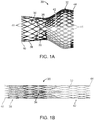
FIG. 1A is a side view of a stented prosthetic heart valve useful with systems, devices and methods of the present disclosure and in a normal, expanded condition; -
FIG. 1B is a side view of the prosthetic heart valve ofFIG. 1A in a compressed condition; -
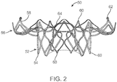
FIG. 2 is a side view of another exemplary prosthetic heart valve stent useful with systems, devices and methods of the present disclosure and in a normal, expanded condition; -
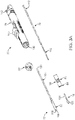
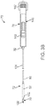
FIG. 3A is an exploded perspective view of a stented prosthetic heart valve delivery device in accordance with principles of the present disclosure; -
FIG. 3B is a side view of the delivery device ofFIG. 3A ; -
FIG. 4 is an exploded perspective view of portions of a deflection assembly in accordance with principles of the present disclosure and useful with the delivery device ofFIG. 3A ; -
FIG. 5A is a side view of the deflection assembly ofFIG. 4 upon final construction and in a linear arrangement; -
FIG. 5B is a side view of the deflection assembly ofFIG. 5A in a deflected arrangement; -
FIG. 6 is a simplified cross-sectional view of the delivery device ofFIG. 3A loaded with a stented prosthetic heart valve; -
FIG. 7 illustrates a portion of a method of implanting a prosthetic heart valve at a mitral valve target location within a heart in accordance with principles of the present disclosure; -
FIG. 8 is a side view of portions of another deflection assembly in accordance with principles of the present disclosure; -
FIG. 9A is a side view of portions of another deflection assembly in accordance with principles of the present disclosure; -
FIG. 9B is a cross-sectional view of the deflection assembly ofFIG. 9A ; -
FIG. 9C is an enlarged perspective view of a hinge segment useful with the deflection assembly ofFIG. 9A ; -
FIG. 10A is a side view of portions of another deflection assembly in accordance with principles of the present disclosure; -
FIG. 10B is a cross-sectional view of the deflection assembly ofFIG. 10A ; -
FIG. 10C is an enlarged perspective view of a hinge segment useful with the deflection assembly ofFIG. 10A ; -
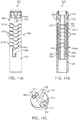
FIG. 11A is a side view of portions of another deflection assembly in accordance with principles of the present disclosure; -
FIG. 11B is a cross-sectional view of the deflection assembly ofFIG. 11A ; and -
FIG. 11C is an enlarged perspective view of a hinge segment useful with the deflection assembly ofFIG. 11A . - Specific embodiments of the present invention are now described with reference to the figures, wherein like reference numbers indicate identical or functionally similar elements. The terms "distal" and "proximal" are used in the following description with respect to a position or direction relative to the treating clinician. "Distal" or "distally" are a position distant from or in a direction away from the clinician. "Proximal" and "proximally" are a position near or in a direction toward the clinician. As used herein with reference to an implanted valve prosthesis, the terms "distal", "outlet", and "outflow" are understood to mean downstream to the direction of blood flow, and the terms "proximal", "inlet", or "inflow" are understood to mean upstream to the direction of blood flow. In addition, as used herein, the terms "outward" or "outwardly" refer to a position radially away from a longitudinal axis of a frame of the valve prosthesis and the terms "inward" or "inwardly" refer to a position radially toward a longitudinal axis of the frame of the valve prosthesis. As well the terms "backward" or "backwardly" refer to the relative transition from a downstream position to an upstream position and the terms "forward" or "forwardly" refer to the relative transition from an upstream position to a downstream position.
- As referred to herein, stented transcatheter prosthetic heart valves useful with and/or as part of the various systems, devices and methods of the present disclosure may assume a wide variety of different configurations, such as a bioprosthetic heart valve having tissue leaflets or a synthetic heart valve having polymeric, metallic or tissue-engineered leaflets, and can be specifically configured for replacing any of the four valves of the human heart. Thus, the stented prosthetic heart valve useful with the systems, devices, and methods of the present disclosure can be generally used for replacement of a native aortic, mitral, pulmonic or tricuspid valve, or to replace a failed bioprosthesis, such as in the area of an aortic valve or mitral valve, for example.
- In general terms, the stented prosthetic heart valves of the present disclosure include a stent or stent frame having an internal lumen maintaining a valve structure (tissue or synthetic), with the stent frame having a normal, expanded condition or arrangement and collapsible to a compressed condition or arrangement for loading within a delivery device. The stent frame is normally constructed to self-deploy or self-expand when released from the delivery device. For example, the stents or stent frames are support structures that comprise a number of struts or wire segments arranged relative to each other to provide a desired compressibility and strength to the prosthetic heart valve. The struts or wire segments are arranged such that they are capable of self-transitioning from a compressed or collapsed condition to a normal, radially expanded condition. The struts or wire segments can be formed from a shape memory material, such as a nickel titanium alloy (e.g., Nitinol™). The stent frame can be laser-cut from a single piece of material, or can be assembled from a number of discrete components.
- With the above understanding in mind, one simplified, non-limiting example of a stented
prosthetic heart valve 30 useful with systems, devices and methods of the present disclosure is illustrated inFIG. 1A . As a point of reference, theprosthetic heart valve 30 is shown in a normal or expanded condition in the view ofFIG. 1A; FIG. 1B illustrates the prosthetic heart valve in a compressed condition (e.g., when compressively retained within an outer catheter or sheath as described below). Theprosthetic heart valve 30 includes a stent orstent frame 32 and avalve structure 34. Thestent frame 32 can assume any of the forms mentioned above, and is generally constructed so as to be self-expandable from the compressed condition (FIG. 1B ) to the normal, expanded condition (FIG. 1A ). - The
valve structure 34 can assume a variety of forms, and can be formed, for example, from one or more biocompatible synthetic materials, synthetic polymers, autograft tissue, homograft tissue, xenograft tissue, or one or more other suitable materials. In some embodiments, thevalve structure 34 can be formed, for example, from bovine, porcine, equine, ovine and/or other suitable animal tissues. In some embodiments, thevalve structure 34 can be formed, for example, from heart valve tissue, pericardium, and/or other suitable tissue. In some embodiments, thevalve structure 34 can include or form one ormore leaflets 36. For example, thevalve structure 34 can be in the form of a tri-leaflet bovine pericardium valve, a bi-leaflet valve, or another suitable valve. In some constructions, thevalve structure 34 can comprise two or three leaflets that are fastened together at enlarged lateral end regions to form commissural joints, with the unattached edges forming coaptation edges of thevalve structure 34. Theleaflets 36 can be fastened to a skirt that in turn is attached to theframe 32. The upper ends of the commissure points can define aninflow portion 38 corresponding to a first orinflow end 40 of theprosthesis 30. The opposite end of the valve can define anoutflow portion 42 corresponding to a second or outflow end 44 of theprosthesis 30. As shown, thestent frame 32 can have a lattice or cell-like structure, and optionally forms or providescrowns 46 and/or eyelets 48 (or other shapes) at the outflow and inflow ends 40, 44. - With the one exemplary construction of
FIGS. 1A and 1B , theprosthetic heart valve 30 can be configured (e.g., sized and shaped) for replacing or repairing an aortic valve. Alternatively, other shapes are also envisioned, adapted to mimic the specific anatomy of the valve to be repaired (e.g., stented prosthetic heart valves useful with the present disclosure can alternatively be shaped and/or sized for replacing a native mitral, pulmonic or tricuspid valve). For example,FIG. 2 illustrates another non-limiting example of astent frame 50 portion of another prosthetic heart valve with which the systems, devices and methods of the present disclosure are useful. In the normal or expanded condition ofFIG. 2 , thestent frame 50 can be sized and shaped for mitral valve implantation. Though not shown, the valve structure attached to thestent frame 50 defines anoutflow portion 52 arranged at a first oroutflow end 54, and aninflow portion 56 arranged at a second orinflow end 58. As compared to thestent frame 32 ofFIG. 1A , theinflow portion 56 can exhibit a more pronounced change in shape relative to thecorresponding outflow portion 52. Regardless, thestent frame 50 can be forced and constrained to a compressed condition (not shown, but akin to the shape ofFIG. 1A ) during delivery, and will self-expand to the natural condition ofFIG. 2 upon removal of the constraining force(s). As a point of reference, in some constructions, thestent frame 50 is configured to be crimped to a diameter on the order of 12 mm during delivery, and will self-expand to the natural, expanded condition that includes theinflow portion 56 having a diameter on the order of 60 mm. As reflected inFIG. 2 , crowns 60 and/or eyelets 62 (or other shapes) optionally can be formed at one or both of the outflow and inflow ends 54, 58. Further, thestent frame 50 can optionally include or carry additional structural components, such as support arm(s) 64. - With the above understanding of the stented prosthetic heart valves in mind, one embodiment of a
delivery device 70 for percutaneously delivering the prosthesis is shown in simplified form inFIGS. 3A and3B . Thedelivery device 70 includes adelivery sheath assembly 72, aninner shaft assembly 74, aninner support assembly 76, ahandle assembly 78, and adeflection assembly 80. Details on the various components are provided below. In general terms, however, thedelivery device 70 combines with a stented prosthetic heart valve (not shown) to form a system for performing a therapeutic procedure on a defective heart valve of a patient. Thedelivery device 70 provides a loaded or delivery state in which a stented prosthetic heart valve is loaded over theinner support assembly 76 and is compressively retained within acapsule 82 of thedelivery sheath assembly 72. For example, the deflection assembly 80 (or the support assembly 76) can include or provide avalve retainer 84 configured to selectively receive a corresponding feature (e.g., posts) provided with the prosthetic heart valve stent frame. Thedelivery sheath assembly 72 can be manipulated to withdraw thecapsule 82 proximally from over the prosthetic heart valve via operation of thehandle assembly 78, permitting the prosthesis to self-expand and partially release from theinner support assembly 76. When thecapsule 82 is retracted proximally beyond thevalve retainer 84, the stented prosthetic heart valve can completely release or deploy from thedelivery device 70. Thedelivery device 70 can optionally include other components that assist or facilitate or control complete deployment. Regardless, thedeflection assembly 80 includes ahinge region 90. As described below, thehinge region 90 is operable to deflect or bend the corresponding segment of the delivery sheath assembly 72 (otherwise disposed over the hinge region 90) in a controlled fashion, effectuating a change in spatial orientation of the inner support assembly 76 (and thus the prosthesis and thecapsule 82 when disposed over the inner support assembly 76) relative to theinner shaft assembly 74 and thehandle assembly 78. - Various features of the components 72-78 reflected in
FIGS. 3A and3B and as described below can be modified or replaced with differing structures and/or mechanisms. Thus, the present disclosure is in no way limited to thedelivery sheath assembly 72, theinner shaft assembly 74, thesupport assembly 76 or thehandle assembly 78 as shown and described below. Any construction that generally facilitates compressed loading of a stented prosthetic heart valve over an inner shaft via a retractable outer sheath or capsule is acceptable. Further, thedelivery device 70 can optionally include additional components or features, such as aflush port assembly 92, a recapture sheath (not shown), etc. - In some embodiments, the
delivery sheath assembly 72 defines proximal anddistal ends capsule 82 and anouter shaft 104. Thedelivery sheath assembly 72 can be akin to a catheter, defining a lumen 106 (referenced generally) that extends from thedistal end 102 through thecapsule 82 and at least a portion of theouter shaft 104. Thelumen 106 can be open at the proximal end 100 (e.g., theouter shaft 104 can be a tube). Thecapsule 82 extends distally from theouter shaft 104, and in some embodiments has a more stiffened construction (as compared to a stiffness of the outer shaft 104) that exhibits sufficient radial or circumferential rigidity to overtly resist the expected expansive forces of the stented prosthetic heart valve (not shown) when compressed within thecapsule 82. For example, theouter shaft 104 can be a polymer tube embedded with a metal braiding, whereas thecapsule 82 includes a laser-cut metal tube that is optionally embedded within a polymer covering. Alternatively, thecapsule 82 and theout shaft 104 can have a more uniform or even homogenous construction (e.g., a continuous polymer tube). Regardless, thecapsule 82 is constructed to compressively retain the stented prosthetic heart valve at a predetermined diameter when loaded within thecapsule 82, and theouter shaft 104 serves to connect thecapsule 82 with thehandle assembly 78. The outer shaft 104 (as well as the capsule 82) is constructed to be sufficiently flexible for passage through a patient's vasculature, yet exhibits sufficient longitudinal rigidity to effectuate desired axial movement of thecapsule 82. In other words, proximal retraction of theouter shaft 104 is directly transferred to thecapsule 82 and causes a corresponding proximal retraction of thecapsule 82. In other embodiments, theouter shaft 104 is further configured to transmit a rotational force or movement onto thecapsule 82. - The
inner shaft assembly 74 can have various constructions appropriate for supporting thedelivery sheath assembly 72, including indirectly supporting the inner support assembly 76 (and a stented prosthetic heart valve disposed thereon) relative to thecapsule 82. In some embodiments, theinner shaft assembly 74 includes an intermediate shaft ortube 110 and a proximal shaft ortube 112. Theintermediate tube 110 is optionally formed of a flexible polymer material (e.g., PEEK), and is sized to be slidably received within thedelivery sheath assembly 72. Theintermediate tube 110 serves as a transition to thedeflection assembly 80, and in some embodiments is a flexible polymer tubing (e.g., PEEK) having a diameter slightly less than that of theproximal tube 112. Theproximal tube 112 can have a more rigid construction, configured for robust assembly with thehandle assembly 78, such as a metal hypotube. Other constructions are also envisioned. For example, in other embodiments, the intermediate andproximal tubes inner shaft assembly 74 forms or defines at least one lumen (not shown) sized, for example, to slidably receive a guide wire (not shown). In other embodiments, theinner shaft assembly 74 can optionally form one or more additional lumens corresponding with one or more pull wire lumens provided with thedeflection assembly 80 as described below. - The
inner support assembly 76 includes aninner support shaft 120 and atip 122. Theinner support shaft 120 is sized to be slidably received within thelumen 106 of thedelivery sheath assembly 72, and is configured for mounting to thedeflection assembly 80. Theinner support shaft 120 can be a flexible polymer tube embedded with a metal braid. Other constructions are also acceptable so long as theinner support shaft 120 exhibits sufficient structural integrity to support a loaded, compressed stented prosthetic heart valve (not shown). Thetip 122 forms or defines a nose cone having a distally tapering outer surface adapted to promote atraumatic contact with bodily tissue. Thetip 122 can be fixed or slidable relative to theinner support shaft 120. Theinner support assembly 76 can define a continuous lumen (not shown) sized to slidably receive an auxiliary component such as a guide wire (not shown). - The
handle assembly 78 generally includes ahousing 140 and one or more actuator mechanisms 142 (referenced generally). Thehousing 140 maintains the actuator mechanism(s) 142, with thehandle assembly 78 configured to facilitate sliding movement of thedelivery sheath assembly 72 relative to other components (e.g., theinner shaft assembly 74, thesupport shaft assembly 76 and the deflection assembly 80). Further, one or more of theactuator mechanisms 142 interfaces with, or is considered part of, thedeflection assembly 80 and is operable by a user to effectuate bending or deflection of thehinge region 90 as described below. Thehousing 140 can have any shape or size appropriate for convenient handling by a user. - With the above general explanations of exemplary embodiments of the components 72-78 in mind, portions of one embodiment of the
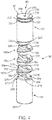
deflection assembly 80 are shown in greater detail inFIG. 4 . Thedeflection assembly 80 includes a plurality ofhinge segments 150, a leadinghub 152 and ajoiner hub 154. In general terms, leadinghub 152 can form or be connected to thevalve retainer 84 that is otherwise configured to selectively engage with corresponding features of the stented prosthetic heart valve. Thejoiner hub 154 is configured for attachment to the inner shaft assembly 74 (FIG. 3A ). Thehinge segments 150 are disposed between the leadinghub 152 and thejoiner hub 154, are can be articulated relative one another via tensioning of a pull wire (not shown) in establishing thehinge region 90. - While
FIG. 4 illustrates thedeflection assembly 80 as including three of thehinge segments 150, any other number, greater or lesser, is also acceptable. In more general terms, thedeflection assembly 80 includes adistal-most hinge segment 150a, aproximal-most hinge segment 150b, and one or moreintermediate hinge segments 150c. Thehinge segments 150 can assume a variety of forms, and in some embodiments are identical. Each of thehinge segments 150 can be a generally disc-shaped body, and defines acentral bore 156. With additional reference toFIG. 5A and as labeled for various ones of thehinge segments 150a-150c, thehinge segment 150 further includes or defines opposing, proximal and distalmajor surfaces platform region 164 and acapture region 166. Theplatform region 164 tapers in thickness from thecapture region 166, extending from a pivot side or edge 170 to a clearance side oredge 172. Thepivot edge 170 is proximate thecapture region 166 whereas theclearance edge 172 is opposite thecapture region 166. Themajor surfaces platform region 164, although the planes of themajor surfaces - The
capture region 166 of eachhinge segment 150 forms complimentary features for engaging with corresponding features of other ones of thehinge segments 150. For example, thecapture region 166 can form aspine 180 and opposing tabs 182 (one of which is visible in the views). Thespine 180 represents a continuation of the distalmajor surface 162 from theplatform region 164, whereas thetabs 182 are defined as projections in the proximalmajor surface 160 from theplatform region 164.Grooves 184 are formed at opposite sides of thespine 180, with eachgroove 184 being aligned with a corresponding one of thetabs 182. Thegrooves 184 represent a recess in the distalmajor surface 162. Similarly, a slot (hidden in the views) is formed between thetabs 182, aligned with thespine 180. The slot represents a recess in the proximalmajor surface 162. - Upon final assembly with the
hinge segments 150 aligned and sequentially arranged (e.g., stacked), thegrooves 184 are each sized and shaped to receive a respective one of thetabs 182 of an identically formedhinge segment 150. The slot is sized and shaped to receive thespine 180 of an identically formedhinge segment 150. For example, as shown inFIG. 5A one of thetabs 182c of theintermediate hinge segment 150c nests within a corresponding one of thegrooves 184b of theproximal-most hinge segment 150b. Similarly, one of thetabs 182a of thedistal-most hinge segment 150a nests within a corresponding one of thegrooves 184c of theintermediate hinge segment 150c. Though primarily hidden in the view ofFIG. 5A , thespine 180c of theintermediate hinge segment 150c nests within the slot of thedistal-most hinge segment 150a, and thespine 180b of theproximal-most hinge segment 150b nests within the slot of theintermediate hinge segment 150c. - Upon final assembly, the central bores 156 (
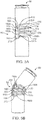
FIG. 4 ) are aligned to permit passage of an object, such as a guide wire (not shown). Further, in the assembled, linear arrangement ofFIG. 5A , aclearance gap 190 is established between thehinge segments 150a-150c along theplatform regions 164. Due to the tapered shape of theplatform regions 164, a size of thegaps 190 increases toward the corresponding clearance edges 172. When thehinge segments 150a-150c are subjected to a tensioning force adjacent the clearance edges 172, thehinge segments 150a-150c are caused to articulate relative to one another, with eachhinge segment 150a-150c pivoting relative to the immediatelyadjacent hinge segment 150a-150c at the pivot edges 170. As a result, thehinge region 90 collectively defined by thehinge segments 150a-150c deflects or forms a bend, as shown inFIG. 5B . This collective deflection or articulation can continue until theplatform regions 164 are forced into contact with one another. In the deflected arrangement ofFIG. 5B , then, thehinge region 90 is deflected to form a bend or curve having an interior curve or radius 200 (referenced generally) and an exterior curve or radius 202 (referenced generally). Theinterior curve 200 is collectively defined by the clearance edges 172. Theexterior curve 202 is collectively defined by thecapture regions 166. As shown, while thecapture regions 166 will articulate relative to, and slightly separate from, one another as thehinge region 90 deflects or articulates, thehinge segments 150a-150c remain robustly engaged via the complimentary features of the capture regions 166 (e.g.,FIGS. 5A and 5B illustrate that thetab 182c of theintermediate hinge segment 150c slides within, but remains nested with, the correspondinggroove 184b of theproximal-most hinge segment 150b; thespine 180c of theintermediate hinge segment 150c slides within, but remains nested with, the slot (referenced generally at 204) of thedistal-most hinge segment 150a; etc.). When the applied tension is reduced or overcome by other forces, thehinge region 90 can readily be reverted back from the deflected arrangement ofFIG. 5B to the linear arrangement ofFIG. 5A . - The deflection-causing tension can be applied to the
hinge region 90 in a variety of manners. In some embodiments, thedeflection assembly 80 includes one or more pull wires (not shown). For example, and returning toFIG. 4 , each of thehinge segments 150 can define apull wire lumen 210 adjacent the corresponding clearance edge 172 (e.g., between thecentral bore 156 and the clearance edge 172). Thepull wire lumen 210 is open to the opposingmajor faces - The leading
hub 152 is a generally cylindrical body (with an outer diameter generally corresponding with that of each of the hinge segments 150) defining a trailingside 220 opposite a leadingside 222. The trailingside 220 is configured to interface with thedistal-most hinge segment 150a in an articulating manner akin to the articulating interface between immediately adjacent ones of thehinge segments 150 as described above. Thus, in some embodiments, the trailingside 220 includes or forms proximally-projecting tabs 226 (one of which is visible inFIG. 4 ) sized and shaped to nest within a corresponding one of thegrooves 184 formed by thedistal-most hinge segment 150a. Further, a slot (hidden in the view) is formed, configured to slidably receive thespine 180 of thedistal-most hinge segment 150a. A trailing face 228 (referenced generally) of the leadinghub 152 is substantially planar for interfacing with the distalmajor surface 162 of thedistal-most hinge segment 150a. With this configuration, the leadinghub 152 effectively serves as a continuation of thehinge region 90, as reflected inFIGS. 5A and 5B . - The leading
side 222 can assume various forms, and in some embodiments forms the valve retainer 84 (or portions thereof). Thevalve retainer 84 is generally configured in accordance with features of the stented prosthetic heart valve (and vice-versa), and is generally configured to assist in loading the prosthesis to thedelivery device 70. For example, in some embodiments, thevalve retainer 84, as formed by the leadinghub 152, includes ahead 230, aneck 232, and ashoulder 234. Theneck 232 has a reduced diameter as compared to thehead 230 and theshoulder 234, establishing a circumferential slot. Further, variousaxial slots 236 can be provided. Theslots 236 are configured to temporarily receive and retain posts or other features provided by the stented prosthetic heart valve. A number of other valve retention configurations are equally acceptable, and the present disclosure is in no way limited to thevalve retainer 84 as shown. Further, while thevalve retainer 84 has been shown as being part of the leadinghub 152, in other embodiments, the valve retainer 84 (or portions thereof) can be provided with other components of the delivery device apart from the leadinghub 152. - The leading
hub 152 can, in some embodiments, form a central bore 240 for slidably receiving a separate component, such as a guide wire (not shown). Upon final arrangement of the leadinghub 152 relative to thehinge segments 150, the central bore 240 of the leadinghub 152 is generally aligned with thecentral bore 156 of thedistal-most hinge segment 150a for reasons made clear below. Further, the leadinghub 152 can include or provide one or more features that facilitate assembly and/or operation of the mechanism utilized to apply deflection-causing tension on to thehinge region 90. For example, where thedeflection assembly 80 incorporates one or more pull wires as described above, the leadinghub 152 can define an axialpull wire lumen 250 at a location off-set from a center line of the leadinghub 152. Thepull wire lumen 250 of the leadinghub 152 corresponds with thepull wire lumen 210 of each of thehinge segments 150. Upon final arrangement of the leadinghub 152 relative to thehinge segments 150, thepull wire lumen 250 of the leadinghub 152 is generally aligned with thepull wire lumen 210 of thedistal-most hinge segment 150a such that a pull wire readily extends between thedistal-most hinge segment 150a and the leadinghub 152. - The
joiner hub 154 is a generally cylindrical body (with an outer diameter generally corresponding with that of each of the hinge segments 150) defining a trailingside 260 opposite a leadingside 262. The trailingside 260 is generally configured for assembly to another component of thedelivery device 70, such as the intermediate shaft 110 (FIG. 3A ). For example, thejoiner hub 154 can form an internally-threaded hole (not shown) at the trailingside 260 that promotes threaded attachment with theintermediate shaft 110. Other connection techniques are equally acceptable. - The leading
side 262 is configured to interface with theproximal-most hinge segment 150b in an articulating manner akin to the articulating interface between immediately adjacent ones of thehinge segments 150 as described above. Thus, in some embodiments, the leadingside 262 includes or forms aplatform region 264 and acapture region 266. A distal face of theplatform region 264 is substantially planar for interfacing with the proximalmajor surface 150 of theproximal-most hinge segment 150b. Thecapture region 266 includes or provides aspine 270 located between opposinggrooves 272. Thespine 270 is configured to be slidably received within the slot (hidden) of theproximal-most hinge segment 150b. Thegrooves 272 are each sized and shaped to receive a corresponding one of thetabs 182 of theproximal-most hinge segment 150b in a nested fashion. With this configuration, thejoiner hub 154 effectively serves as a continuation of thehinge region 90, as reflected inFIGS. 5A and 5B . - The
joiner hub 154 can, in some embodiments, form acentral bore 274 for slidably receiving a separate component, such as a guide wire (not shown). Upon final arrangement of thejoiner hub 154 relative to thehinge segments 150, thecentral bore 274 of thejoiner hub 154 is generally aligned with thecentral bore 156 of theproximal-most hinge segment 150b for reasons made clear below. Further, thejoiner hub 154 can include or provide one or more features that facilitate assembly and/or operation of the mechanism utilized to apply deflection-causing tension on to thehinge region 90. For example, where thedeflection assembly 80 incorporates one or more pull wires as described above, thejoiner hub 154 can define an axialpull wire lumen 276 at a location off-set from a center line of thejoiner hub 154. Thepull wire lumen 276 of thejoiner hub 154 corresponds with thepull wire lumen 210 of each of thehinge segments 150. Upon final arrangement of thejoiner hub 154 relative to thehinge segments 150, thepull wire lumen 276 of thejoiner hub 154 is generally aligned with thepull wire lumen 210 of theproximal-most hinge segment 150b such that a pull wire readily extends between thejoiner hub 154 and theproximal-most hinge segment 150b. - The
hinge segments 150, the leadinghub 152, and thejoiner hub 154 are, in some embodiments, formed of an identical or substantially identical material, such as a surgically safe plastic material. Thehinge segments 150, the leadinghub 152, and thejoiner hub 154 are each formed as solid bodies, such as by a molding or machining process, with various features described above (e.g., tabs, grooves, spines, etc.) being molded or machined into the part. Regardless, each of thehinge segments 150 is discrete from one another, as well as from the leadinghub 152 and thejoiner hub 154. That is to say, the components 150-154 of thedeflection assembly 80 are each a solid body, are not hollow, and are not commonly formed from a homogenous tube (e.g., the components 150-154 are not cut (for example, laser cut) from a single metal tube). - As alluded to above, final construction of the
deflection assembly 80 is shown inFIG. 5A (it being understood that the optional pull wire(s) is omitted from the view). Thejoiner hub 154, thehinge segments 150, and leadinghub 152 are longitudinally arranged or aligned in a sequential or stacked fashion. Adjacent ones of thehinge segments 150 are connected so as to permit articulating movement of eachhinge segments 150 relative to one another as described above. A similar articulating interface is established between the leadinghub 152 and thedistal-most hinge segment 150a (e.g., thetabs 226 of the leadinghub 152 nest within respective ones of thegrooves 184 formed by thedistal-most hinge segment 150a). A similar articulating interface is further established between theproximal-most hinge segment 150b and the joiner hub 154 (e.g., thetabs 182 of theproximal-most hinge segment 150b nest within respective ones of thegrooves 272 of the joiner hub 154). As a result, thedeflection assembly 80 can be readily transitioned between the linear arrangement ofFIG. 5A and the deflected arrangement ofFIG. 5B . With additional reference toFIG. 4 , thecentral bores deflection assembly 80, with the auxiliary component being force to assume the shape of the hinge region 90 (i.e., when thedeflection assembly 80 is deflected from the linear arrangement ofFIG. 5A to the deflected arrangement ofFIG. 5B , the guide wire or other auxiliary component extending through thecentral bores - With embodiments in which one or more pull wires are provided with the
deflection assembly 80 to facilitate user-prompted articulation between the linear and deflected arrangements, the pull wire (not shown) can be received through thepull wire lumens joiner hub 154, for example to the handle assembly 78 (FIGS. 3A and3B ), and is connected to a user actuator. A distal end of the pull wire(s) is rigidly connected to the leading hub 152 (e.g., the distal end of the pull wire extends throughpull wire lumen 250 of the leadinghub 152 and is held (e.g., via a knot or other coupling body) at the leading side 222). With this construction, a pulling or tensioning force applied to a proximal region of the pull wire(s) is transferred on to the leadinghub 152, pulling or compressing the leadinghub 152 toward the joiner hub 154 (that is otherwise held spatially stationary while tension is applied to the pull wire(s) via the inner shaft assembly 74 (FIG. 3A )). Thehinge segments 150 are compressed toward one another between thehubs hinge region 90 to articulate to the deflected arrangement ofFIG. 5B . - The
deflection assembly 80 is configured to be structurally robust such that any change in shape of thehinge region 90 is imparted on to any structure surrounding thehinge region 90. For example, a simplified representation of portions of thedelivery device 70 in the delivery state and loaded with the stented prosthetic heart valve 30 (referenced generally) to provide asystem 300 for performing a therapeutic procedure on a defective heart valve is shown inFIG. 6 . For ease of illustration, only thestent frame 32 of theprosthesis 30 is depicted inFIG. 6 . Thestent frame 32 is crimped over theinner support shaft 120, and is compressibly held in the compressed condition by thecapsule 82. Further, thestent frame 32 is connected to thevalve retainer 84. The leadinghub 152 is attached to theinner support shaft 120. Thejoiner hub 154 is attached to theintermediate shaft 110. As shown, theouter shaft 104 of thedelivery sheath assembly 72 is coaxially received over the leadinghub 152, thehinge segments 150, and thejoiner hub 154. As thehinge region 90 is caused to deflect or articulate from the linear arrangement shown to a deflected arrangement (as inFIG. 5B , for example), theouter shaft 104 conforms to or with the deflected shape defined along thehinge region 90. Further, the leadinghub 152 is spatially reoriented relative to thejoiner hub 154; this movement, in turn, is transferred to theinner support shaft 120 and thus theprosthesis 30 carried thereon. As a result, articulation of thehinge region 90 spatially re-orients the prosthesis 30 (and all other components distal the hinge region 90) relative tojoiner hub 154 and thus the intermediate shaft 110 (and all other components proximal the joiner hub 154). Notably, the deflection assemblies of the present disclosure are capable of generating the above-described deflection even when disposed within a relatively large delivery sheath or catheter, for example a delivery sheath or catheter having an inner diameter on the order of 12-13 mm. - The delivery devices of the present disclosure can be used to deliver a number of different implantable articles to a various target sites in the human body. For example,
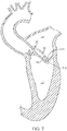
FIG. 7 generally reflects use of thedelivery device 70 in delivering a stented prosthetic heart valve (hidden) to a mitralvalve target site 310. The mitralvalve target site 310 separates the left atrium LA and the left ventricle LV. Thedelivery device 70 is shown after having been introduced into the vasculature via a percutaneous entry point (e.g., the Seldinger technique), and having been tracked through the vasculature and into the left atrium LA. For example, the percutaneous entry point may be formed in a femoral vein. Thereafter, a guide wire (not shown) is advanced through the circulatory system, eventually arriving at the heart. The guide wire is directed into the right atrium, traverses the right atrium and is made to puncture, with the aid of a transeptal needle or pre-existing hole, the atrial septum, thereby entering the left atrium LA. Once the guide wire is positioned, the endoluminal entry port and the atrial septum are dilated to permit entry of a guide catheter (not shown) and/or thedelivery device 70 into the left atrium LA. Once in the left atrium LA, the deflection assembly 80 (referenced generally) is operated or caused to deflect to the deflected arrangement shown inFIG. 7 , aligning adistal end 312 of thedelivery device 70 with the mitralvalve target site 310. Notably, the outer delivery sheath capsule 82 (as well as the stented prosthetic heart valve constrained therein) is caused to move to the aligned position with deflection of thedeflection assembly 80. - Although the
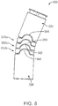
deflection assembly 80 has been described as effecting an off-set hinge arrangement (e.g., the pivot point of the various assembly components relative to one another, for example the hinge segments 150 (FIG. 4 ), is off-set relative to an axial centerline), other constructions are also envisioned. For example,FIG. 8 is a simplified view of portions of anotherembodiment defection assembly 350 in accordance with principles of the present disclosure. Thedeflection assembly 350 includes a plurality of hinge segments 352, a leadinghub 354, and ajoiner hub 356. As tension-applying device (e.g., one or more pull wires) can also be included, but are omitted from the view for ease of illustration. - The hinge segments 352 can be highly akin to the hinge segments 150 (
FIG. 4 ) described above, and generally include or form various complimentary features that promote an articulating interface between consecutively stacked or arranged ones of the hinge segments 352 (as well as between adistal-most hinge segment 352a and the leadinghub 354, and between aproximal-most hinge segment 352b and the joiner hub 356). For example, each of the hinge segments 352 can include or form opposing tabs 360 (one of which is visible inFIG. 8 ) and opposing grooves 362 (one of which is visible inFIG. 8 ). Thetabs 360 and thegrooves 362 have a complimentary size and shape, such that thetab 360 of one hinge segment is slidably received or nested with acorresponding groove 362 of an immediatelyadjacent hinge segment 350. The leadinghub 354 and thejoiner hub 356 form or provide corresponding interface features (e.g., the leadinghub 354 forms opposing grooves 364 (one of which is visible inFIG. 8 ) for receiving a corresponding one of thetabs 360 of thedistal-most hinge segment 352a, whereas thejoiner hub 356 forms or provides opposing tabs 366 (one of which is visible inFIG. 8 ) sized to slidably nest within a corresponding one of thegrooves 362 of theproximal-most hinge segment 352b. Regardless, a hinged or articulating interface is established between adjacent ones of the components 352-356 upon final assembly, with the pivot point or line approximately intersecting an axial centerline of the corresponding component 352-356. In some embodiments, the off-set pivot arrangement (as inFIG. 4 ) may be desired where an increased lever effect is of interest. - Returning to
FIG. 4 , in some embodiments thehinge segments 150, the leadinghub 152 and thejoiner hub 154 can be generally maintained relative to one another by the pull wire(s) or other tension-applying mechanism. In other embodiments, the deflection assemblies of the present disclosure can include additional features that more directly join immediately adjacent ones of the components 150-154 relative to one another. As a point of reference, in some instances it may be desirable to limit separation of the components 150-156 relative to one another, for example when loading a stented prosthetic heart valve on to thedelivery device 70. For example, and with additional reference toFIG. 6 , one loading technique entails holding the stentedprosthetic heart valve 30 in a compressed condition while thedelivery sheath assembly 72 is moved distally to sequentially direct thecapsule 82 over theprosthesis 30. Under these circumstances, a tension or pulling force will be applied on to the leading hub 152 (e.g., as thecapsule 82 is moved distally, thecapsule 82 will tend to apply a distal force on to theprosthesis 30, and thus on to the leading hub 152). Absent a more robust connection between the leadinghub 152 and the distal-most hinge segment 150 (as well as between immediately adjacent ones of thehinge segments 150, and between theproximal-most hinge segment 150 and the joiner hub 154), the components 150-154 might undesirably separate from one another. - With the above in mind, portions of another
embodiment deflection assembly 400 in accordance with principles of the present disclosure are shown inFIGS. 9A and 9B . Thedeflection assembly 400 includes a plurality ofhinge segments 402, a leadinghub 404, and ajoiner hub 406. In general terms, thehinge segments 402 can be highly akin to the hinge segments 150 (FIG. 4 ), and can incorporate any of the features described above. Similarly, the leadinghub 404 can be highly akin to the leading hub 152 (FIG. 4 ), and thejoiner hub 406 can be highly akin to the joiner hub 154 (FIG. 4 ). The leadinghub 404 can optionally formslots 407 for receiving respective components of a prosthetic heart valve (e.g., respective ones of thecrowns 60 oreyelets 62 shown inFIG. 2 ). Regardless, an articulating interface is established between consecutive ones of the components 402-406 upon final assembly to collectively define ahinge region 408 as described above. In addition, thedeflection assembly 400 includes one or more pins securing immediately adjacent ones of the components 402-406 to one another. For example, and as best shown inFIG. 9B , the leadinghub 404 is connected to thedistal-most hinge segment 402a bypins pins hub 404 can articulate relative to thedistal-most hinge segment 402a (and vice-versa), pivoting or rotating about thepins hinge segments 402 are similarly secured to one another by twopins proximal-most hinge segment 402b to thejoiner hub 406. - The
pins pins FIG. 9C illustrates one of thehinge segments 402 in greater detail. Commensurate with previous descriptions, thehinge segment 402 can form or provide opposing tabs 420 (one of which is visible in the view) and opposinggrooves 422. Acentral bore 424 is optionally provided, as is an optional pull wire lumen(s) 426. In addition, thehinge segment 402 forms afirst hole 428 within or at each of thegrooves 422, and asecond hole 430 at or along each of the tabs 420 (it being understood that in the view ofFIG. 9C , only one set of theholes hinge segments 402 to a second one of the hinge segments 402 (e.g., in which thetabs 420 of thefirst hinge segment 402 nest within thegrooves 422 of the second hinge segment), corresponding ones of theholes pins 410, 412 (FIG. 9B ). The leadinghub 404 and thejoiner hub 406 can provide similar features or holes. - With the above construction, the
hinge region 408 can articulate or deflect in accordance with previous descriptions (e.g., in response to a compressive force applied to the leadinghub 404 in a direction of the joiner hub 406). Further, when placed in tension (e.g., a distal pulling force applied to the leadinghub 404 while thejoiner hub 406 is held stationary), thepins deflection assembly 400 from pulling apart. - Portions of another
embodiment deflection assembly 450 in accordance with principles of the present disclosure are shown inFIGS. 10A and 10B . Thedeflection assembly 450 includes a plurality ofhinge segment 452, a leadinghub 454, and ajoiner hub 456. In general terms, thehinge segments 452 can be highly akin to the hinge segments 150 (FIG. 4 ), and can incorporate any of the features described above. Similarly, the leadinghub 454 can be highly akin to the leading hub 152 (FIG. 4 ), and thejoiner hub 456 can be highly akin to the joiner hub 154 (FIG. 4 ). Thus, an articulating interface is established between consecutive ones of the components 452-456 upon final assembly to collectively define ahinge region 458 as described above. In addition, thedeflection assembly 450 includes one or more wires securing immediately adjacent ones of the components 452-456 to one another. - For example,
FIG. 10A , illustrates afirst wire 460 extending between the leadinghub 454 and thejoiner hub 456, and interconnected with each of thehinge segments 452. As generally reflected byFIG. 10B , asecond wire 462 is similarly connected to the components 452-456 opposite thefirst wire 460. Thewires hub 454 can articulate relative to thedistal-most hinge segment 452a (and vice-versa), adjacent ones of thehinge segments 452 can articulate relative to one another, and theproximal-most hinge segment 452b to the joiner hub 456 (and vice-versa). Finally, thewires hub 454 and thejoiner hub 456, and thus retain the components 452-456 as a collective unit. - The
wires hub 454 can form opposingpockets corresponding wire lumen FIG. 10A , acrimp 480 is formed at, or attached to, a distal end of thefirst wire 460. Thecrimp 480 is sized and shaped to dock or lodge within thefirst pocket 470. Though not shown, a similar assembly is provided for thesecond wire 462 relative to thesecond pocket 472. Thefirst wire 460 is then fed through the first wire lumen 474 (and thesecond wire 462 through the second wire lumen 476). First andsecond notches joiner hub 456 and fixedly receive acrimp 494 at a proximal end of the each of thewires -
FIG. 10C illustrates one of thehinge segments 452 in greater detail. Commensurate with previous descriptions, thehinge segment 452 can form or provide opposingtabs grooves central bore 508 is optionally provided, as is an optional pull wire lumen(s) 510. In addition, thehinge segment 452 forms afirst wire lumen 512 through thefirst tab 500, and asecond wire lumen 514 through thesecond tab 502. Upon stacked arrangement of a first one of thehinge segments 452 to a second one of the hinge segments 452 (e.g., in which thetabs first hinge segment 452 nest within thegrooves wire lumens wires 460, 462 (FIGS. 10A and 10B ). Construction of thedeflection assembly 450 thus entails advancing the first wire 460 (otherwise attached to the leadinghub 454 as described above) through thefirst wire lumen 512 of each of the alignedhinge segments 452, and advancing thesecond wire 462 through thesecond wire lumen 514. Thecrimp 494 is then attached to the proximal end of thefirst wire 460 and docked to thefirst notch 490 of the joiner hub 456 (and thecrimp 494 attached to the proximal end of thesecond wire 462 is docked to the second notch 492). - With the above construction, the
hinge region 458 can articulate or deflect in accordance with previous descriptions (e.g., in response to a compressive force applied to the leadinghub 454 in a direction of the joiner hub 456). Further, when placed in tension (e.g., a distal pulling force applied to the leadinghub 454 while thejoiner hub 456 is held stationary), thewires deflection assembly 450 from pulling apart. - Portions of another
embodiment deflection assembly 550 in accordance with principles of the present disclosure are shown inFIGS. 11A and 11B . Thedeflection assembly 550 includes a plurality ofhinge segment 552, a leadinghub 554, and ajoiner hub 556. In general terms, thehinge segments 552 can be highly akin to the hinge segments 150 (FIG. 4 ), and can incorporate any of the features described above. Similarly, the leadinghub 554 can be highly akin to the leading hub 152 (FIG. 4 ), and thejoiner hub 556 can be highly akin to the joiner hub 154 (FIG. 4 ). Thus, an articulating interface is established between consecutive ones of the components 552-556 upon final assembly to collectively define ahinge region 558 as described above. In addition, thedeflection assembly 550 includes one or more wires securing immediately adjacent ones of the components 552-556 to one another. - For example,
FIG. 11A , illustrates afirst wire 560 extending between the leadinghub 554 and thejoiner hub 556, and interconnected with each of thehinge segments 552. As generally reflected byFIG. 11B , asecond wire 562 is similarly connected to the components 552-556 opposite thefirst wire 560. Thewires hub 554 can articulate relative to thedistal-most hinge segment 552a (and vice-versa), adjacent ones of thehinge segments 552 can articulate relative to one another, and theproximal-most hinge segment 552b to the joiner hub 556 (and vice-versa). Finally, thewires hub 554 and thejoiner hub 556, and thus retain the components 552-556 as a collective unit. - The
wires hub 554 can form opposingpockets corresponding wire lumen joiner hub 556 can include opposingslots finger FIG. 11C illustrates one of thehinge segments 552 in greater detail. Commensurate with previous descriptions, thehinge segment 552 can form or provide opposingtabs grooves central bore 608 is optionally provided, as is an optional pull wire lumen(s) 610. In addition, thehinge segment 552 forms afirst wire lumen 612 through thefirst tab 600, and asecond wire lumen 614 through thesecond tab 602. Upon stacked arrangement of a first one of thehinge segments 552 to a second one of the hinge segments 552 (e.g., in which thetabs first hinge segment 552 nest within thegrooves wire lumens wires 560, 562 (FIGS. 11A and 11B ). - Construction of the
deflection assembly 550 can generally entail forming a knot or a crimp in the distal end of each of thewires corresponding pocket hub 554. Glue or other adhesive can optionally be applied to the loaded distal end to prevent thewire first wire 560 is advanced through thefirst wire lumen 612 of each of the alignedhinge segments 552, and thesecond wire 562 is advanced through thesecond wire lumens 614. Thefirst wire 560 is guided through thefirst slot 580 and secured against thefirst finger 584 of thejoiner hub 556. Thesecond wire 562 is similarly connected to thesecond finger 586. Glue or other adhesive can optionally be applied to further secure thewires corresponding finger - With the above construction, the
hinge region 558 can articulate or deflect in accordance with previous descriptions (e.g., in response to a compressive force applied to the leadinghub 554 in a direction of the joiner hub 556). Further, when placed in tension (e.g., a distal pulling force applied to the leadinghub 554 while thejoiner hub 556 is held stationary), thewires deflection assembly 550 from pulling apart. - The delivery devices, systems and methods of the present disclosure provide a marked improvement over previous designs. By providing the delivery device with a robust deflection assembly coaxially within the delivery sheath and immediately proximal the loaded stented prosthetic heart valve, the delivery device can be readily operated to effectuate desired bends or deflections commensurate with a desired delivery path presented by the anatomy of the particular procedure, even with more rigid or large outer sheath or catheter designs.
- Although the present disclosure has been described with reference to preferred embodiments, workers skilled in the art will recognize that changes can be made in form and detail without departing from the spirit and scope of the present disclosure. For example, while the devices and systems of the present disclosure have been described as being useful for delivering a stented prosthetic heart valve, a number of other implantable devices can be employed.
- Further disclosed herein is the subject-matter of the following clauses:
- 1. A delivery device for implanting a stented prosthetic heart valve, the device comprising:
- an outer sheath;
- an inner shaft disposed within the outer sheath;
- a deflection assembly attached to the inner shaft and including:
- a plurality of stacked hinge segments, including a proximal-most hinge segment and a distal-most hinge segment, wherein each of the hinge segments are discretely formed as a solid body, and have complimentary engagement features by which immediately adjacent ones of the hinge segments interface with, and can articulate relative to, one another,
- a joiner hub connected to the inner shaft and interfacing with the proximal-most hinge segment,
- a leading hub interfacing with the distal-most hinge segment; and
- a support shaft attached to and extending distally from the leading hub;
- wherein the delivery device is configured to provide a loaded state in which a stented prosthetic heart valve is compressed over the support shaft and retained within a capsule of the outer sheath;
- and further wherein a hinge region of the deflection assembly is configured to be deflected by a user to change a spatial orientation of the support shaft relative to the inner shaft while the delivery device is in the loaded state.
- 2. The delivery device of clause 1, wherein the complimentary engagement features include a first tab and a first groove.
- 3. The delivery device of clause 2, wherein each of the hinge segments defines opposing, first and second major surfaces, and further wherein the first tab is formed as a projection along the first major surface and the first groove is formed as a recess in the second major surface.
- 4. The delivery device of clause 2, wherein the plurality of stacked hinge segments further includes first and second intermediate hinge segments, and further wherein the first tab of the first intermediate hinge segment is nested within the first groove of the second intermediate hinge segment.
- 5. The delivery device of clause 2, wherein the first groove is open to a side of the corresponding hinge segment.
- 6. The delivery device of clause 2, wherein the complimentary engagement features further include a second tab and a second groove.
- 7. The delivery device of clause 6, wherein each of the hinge segments defines opposing, first and second major surfaces, and further wherein the first and second tabs are formed as projections along the first major surface, and the first and second grooves are formed as recesses in the second major surface.
- 8. The delivery device of clause 7, wherein the plurality of stacked hinge segments further includes first and second intermediate hinge segments, and further wherein the first and second tabs of the first intermediate hinge segment are nested within the first and second grooves, respectively of the second intermediate hinge segment.
- 9. The delivery device of clause 1, wherein each of the stacked hinge segments, the joiner hub and the leading hub define a central bore for slidably receiving a guide wire.
- 10. The delivery device of clause 9, further comprising a pull wire attached to the leading hub and extending through each of the hinge segments and the joiner hub apart from the corresponding central bore.
- 11. The delivery device of clause 1, wherein the proximal-most hinge segment is pivotably attached to the joiner hub by at least a first pin.
- 12. The delivery device of clause 1, further comprising a first wire having opposing, first and second ends, wherein the wire extends through each of the hinge segments, and further wherein the first end is attached to the leading hub and the second end is attached to the joiner hub.
- 13. The delivery device of clause 1, wherein the deflection assembly is configured to be repeatedly translated between a linear arrangement and a deflected arrangement, and further wherein the linear arrangement includes a clearance gap being defined between immediately adjacent ones of the hinge segments at one side thereof.
- 14. The delivery device of clause 1, wherein the leading hub includes a valve retainer.
- 15. The delivery device of clause 14, wherein the valve retainer includes a first slot configured to receive a portion of a stent of a prosthetic heart valve.
- 16. A system for treating a defective heart valve, the system comprising:
- a delivery device comprising:
- an outer sheath,
- an inner shaft disposed within the outer sheath,
- a deflection assembly attached to the inner shaft and including:
- a plurality of stacked hinge segments, including a proximal-most hinge segment and a distal-most hinge segment, wherein each of the hinge segments are discretely formed as a solid body, and have complimentary engagement features by which immediately adjacent ones of the hinge segments interface with, and can articulate relative to, one another,
- a joiner hub connected to the inner shaft and interfacing with the proximal-most hinge segment,
- a leading hub interfacing with the distal-most hinge segment, and
- a support shaft attached to and extending distally from the leading hub,
- wherein a hinge region of the deflection assembly is configured to be deflected by a user to change a spatial orientation of the support shaft relative to the inner shaft while the delivery device is in a loaded state; and
- a prosthetic heart valve compressed over the support shaft and retained within a capsule of the outer sheath in the loaded state.
- a delivery device comprising:
- 17. The system of clause 16, further comprising:
a guide wire slidably received within a central bore of each of the hinge segments, the joiner hub and the leading hub. - 18. The system of clause 16, wherein the prosthetic heart valve is selectively secured to a valve retainer of the leading hub in the loaded state.
- 19. The system of clause 18, wherein the prosthetic heart valve includes a stent frame, and further wherein the valve retainer includes a slot sized to selectively receive a portion of the stent frame.
- 20. The system of clause 16, wherein the complimentary engagement features include a first tab and a first groove.
Claims (15)
- A delivery device (70) for implanting a stented prosthetic heart valve (30), the device comprising:an outer sheath (104);an inner shaft (110) disposed within the outer sheath (104);a deflection assembly (80, 400, 450, 550) attached to the inner shaft (110) and including:a plurality of hinge segments (150, 352, 402, 452, 552), ,a joiner hub (154, 356, 406,456, 566), anda leading hub (152, 404, 454, 554); anda support shaft (120) attached to and extending distally from the leading hub (152, 404, 454, 554);wherein the delivery device (70) is configured to provide a loaded state in which a stented prosthetic heart valve (30) is compressed over the support shaft (120) and retained within a capsule (82) of the outer sheath (104);and further wherein a hinge region (90, 408, 458, 558) of the deflection assembly (80, 400, 450, 550) is configured to be deflected by a user to change a spatial orientation of the support shaft (120) relative to the inner shaft (110) while the delivery device (70) is in the loaded state.
- The delivery device (70) of claim 1, wherein the plurality of hinge segments is a plurality of stacked hinge segments (150, 352, 402, 452, 552), including a proximal-most hinge segment (150b, 352b, 402b, 452b, 552b) and a distal-most hinge segment (150a, 352a, 402a, 452a, 552a), wherein each of the hinge segments (150, 352, 402, 452, 552) are discretely formed as a solid body, and have complimentary engagement features (182, 184, 226, 272, 360, 362, 366, 364, 420, 422, 500, 502, 504, 506, 600, 602, 604, 606) by which immediately adjacent ones of the hinge segments (150, 352, 402, 452, 552) interface with, and can articulate relative to, one another,
- The delivery device (70) of claim 2, wherein the complimentary engagement features (182, 184, 226, 272, 360, 362, 366, 364, 420, 422, 500, 502, 504, 506, 600, 602, 604, 606) include a first tab (500, 600) and a first groove (504, 604), wherein optionally each of the hinge segments (150, 352, 402, 452, 552) defines opposing, first and second major surfaces (160, 162), and further wherein the first tab (500, 600) is formed as a projection along the first major surface (160) and the first groove (504, 604) is formed as a recess in the second major surface (162).
- The delivery device (70) of claim 3, wherein the plurality of stacked hinge segments (150, 352, 402, 452, 552) further includes first and second intermediate hinge segments (150c), and further wherein the first tab (500, 600) of the first intermediate hinge segment (150c) is nested within the first groove (504, 604) of the second intermediate hinge segment (150c).
- The delivery device (70) of claim 3, wherein the first groove (504, 604) is open to a side of the corresponding hinge segment.
- The delivery device (70) of claim 3, wherein the complimentary engagement features further include a second tab and a second groove; wherein optionally each of the hinge segments (150, 352, 402, 452, 552) defines opposing, first and second major surfaces (160, 162), and further wherein the first and second tabs (500, 502, 600, 602) are formed as projections along the first major surface (160), and the first and second grooves (504, 506, 604, 606) are formed as recesses in the second major surface (162);
wherein optionally the plurality of stacked hinge segments (150, 352, 402, 452, 552) further includes first and second intermediate hinge segment (150c)s, and further wherein the first and second tabs (500, 502, 600, 602) of the first intermediate hinge segment (150c) are nested within the first and second grooves (504, 506, 604, 606), respectively of the second intermediate hinge segment (150c). - The delivery device (70) of claim 1, wherein each of the stacked hinge segments (150, 352, 402, 452, 552), the joiner hub (154, 356, 406,456, 566) and the leading hub (152, 404, 454, 554) define a central bore (156, 240, 274) for slidably receiving a guide wire; optionally the delivery device (70) further comprising a pull wire attached to the leading hub (152, 404, 454, 554) and extending through each of the hinge segments (150, 352, 402, 452, 552) and the joiner hub (154, 356, 406,456, 566) apart from the corresponding central bore (156, 240, 274).
- The delivery device (70) of claim 1, wherein the proximal-most hinge segment (150b, 352b, 402b, 452b, 552b) is pivotably attached to the joiner hub (154, 356, 406,456, 566) by at least a first pin (410, 412).
- The delivery device (70) of claim 1, further comprising a first wire (460) having opposing, first and second ends, wherein the wire extends through each of the hinge segments (150, 352, 402, 452, 552), and further wherein the first end is attached to the leading hub (152, 404, 454, 554) and the second end is attached to the joiner hub (154, 356, 406,456, 566).
- The delivery device (70) of claim 1, wherein the deflection assembly (80, 400, 450, 550) is configured to be repeatedly translated between a linear arrangement and a deflected arrangement, and further wherein the linear arrangement includes a clearance gap (190) being defined between immediately adjacent ones of the hinge segments (150, 352, 402, 452, 552) at one side thereof.
- The delivery device (70) of claim 1, wherein the leading hub (152, 404, 454, 554) includes a valve retainer which optionally includes a first slot configured to receive a portion of a stent of a prosthetic heart valve (30).
- A system for treating a defective heart valve (30), the system comprising the delivery device (70) of any preceding claim, wherein
a prosthetic heart valve (30) is compressed over the support shaft (120) and retained within a capsule (82) of the outer sheath (104) in the loaded state. - The system of claim 12, further comprising:
a guide wire slidably received within a central bore (156, 240, 274) of each of the hinge segments (150, 352, 402, 452, 552), the joiner hub (154, 356, 406,456, 566) and the leading hub (152, 404, 454, 554). - The system of claim 12, wherein the prosthetic heart valve (30) is selectively secured to a valve retainer (84) of the leading hub (152, 404, 454, 554) in the loaded state; wherein optionally the prosthetic heart valve (30) includes a stent frame (32), and further wherein the valve retainer (84) includes a slot (236, 407) sized to selectively receive a portion of the stent frame (32).
- The system of claim 12, wherein the complimentary engagement features include a first tab (500, 600) and a first groove (504, 604).
Applications Claiming Priority (3)
| Application Number | Priority Date | Filing Date | Title |
|---|---|---|---|
| US201461980930P | 2014-04-17 | 2014-04-17 | |
| EP15717768.4A EP3131503B1 (en) | 2014-04-17 | 2015-04-08 | Hinged transcatheter prosthetic heart valve delivery system |
| PCT/US2015/024982 WO2015160598A1 (en) | 2014-04-17 | 2015-04-08 | Hinged transcatheter prosthetic heart valve delivery system |
Related Parent Applications (1)
| Application Number | Title | Priority Date | Filing Date |
|---|---|---|---|
| EP15717768.4A Division EP3131503B1 (en) | 2014-04-17 | 2015-04-08 | Hinged transcatheter prosthetic heart valve delivery system |
Publications (2)
| Publication Number | Publication Date |
|---|---|
| EP3552585A1 true EP3552585A1 (en) | 2019-10-16 |
| EP3552585B1 EP3552585B1 (en) | 2022-10-26 |
Family
ID=52992014
Family Applications (2)
| Application Number | Title | Priority Date | Filing Date |
|---|---|---|---|
| EP19178780.3A Active EP3552585B1 (en) | 2014-04-17 | 2015-04-08 | Hinged transcatheter prosthetic heart valve delivery system |
| EP15717768.4A Active EP3131503B1 (en) | 2014-04-17 | 2015-04-08 | Hinged transcatheter prosthetic heart valve delivery system |
Family Applications After (1)
| Application Number | Title | Priority Date | Filing Date |
|---|---|---|---|
| EP15717768.4A Active EP3131503B1 (en) | 2014-04-17 | 2015-04-08 | Hinged transcatheter prosthetic heart valve delivery system |
Country Status (4)
| Country | Link |
|---|---|
| US (1) | US10368989B2 (en) |
| EP (2) | EP3552585B1 (en) |
| CN (1) | CN106170270B (en) |
| WO (1) | WO2015160598A1 (en) |
Cited By (6)
| Publication number | Priority date | Publication date | Assignee | Title |
|---|---|---|---|---|
| US11602429B2 (en) | 2019-04-01 | 2023-03-14 | Neovasc Tiara Inc. | Controllably deployable prosthetic valve |
| US11617650B2 (en) | 2012-05-30 | 2023-04-04 | Neovasc Tiara Inc. | Methods and apparatus for loading a prosthesis onto a delivery system |
| US11737872B2 (en) | 2018-11-08 | 2023-08-29 | Neovasc Tiara Inc. | Ventricular deployment of a transcatheter mitral valve prosthesis |
| US11779742B2 (en) | 2019-05-20 | 2023-10-10 | Neovasc Tiara Inc. | Introducer with hemostasis mechanism |
| US11793640B2 (en) | 2017-08-25 | 2023-10-24 | Neovasc Tiara Inc. | Sequentially deployed transcatheter mitral valve prosthesis |
| US11931254B2 (en) | 2019-06-20 | 2024-03-19 | Neovasc Tiara Inc. | Low profile prosthetic mitral valve |
Families Citing this family (78)
| Publication number | Priority date | Publication date | Assignee | Title |
|---|---|---|---|---|
| AU2004324043A1 (en) | 2004-10-02 | 2006-04-20 | Christoph Hans Huber | Methods and devices for repair or replacement of heart valves or adjacent tissue without the need for full cardiopulmonary support |
| US8092520B2 (en) | 2005-11-10 | 2012-01-10 | CardiAQ Technologies, Inc. | Vascular prosthesis connecting stent |
| WO2008013915A2 (en) | 2006-07-28 | 2008-01-31 | Arshad Quadri | Percutaneous valve prosthesis and system and method for implanting same |
| EP2367505B1 (en) | 2008-09-29 | 2020-08-12 | Edwards Lifesciences CardiAQ LLC | Heart valve |
| CA2961053C (en) | 2009-04-15 | 2019-04-30 | Edwards Lifesciences Cardiaq Llc | Vascular implant and delivery system |
| US20110313515A1 (en) | 2010-06-21 | 2011-12-22 | Arshad Quadri | Replacement heart valve |
| US8579964B2 (en) | 2010-05-05 | 2013-11-12 | Neovasc Inc. | Transcatheter mitral valve prosthesis |
| WO2012040655A2 (en) | 2010-09-23 | 2012-03-29 | Cardiaq Valve Technologies, Inc. | Replacement heart valves, delivery devices and methods |
| US9554897B2 (en) | 2011-04-28 | 2017-01-31 | Neovasc Tiara Inc. | Methods and apparatus for engaging a valve prosthesis with tissue |
| US9308087B2 (en) | 2011-04-28 | 2016-04-12 | Neovasc Tiara Inc. | Sequentially deployed transcatheter mitral valve prosthesis |
| US9668859B2 (en) | 2011-08-05 | 2017-06-06 | California Institute Of Technology | Percutaneous heart valve delivery systems |
| US9730791B2 (en) | 2013-03-14 | 2017-08-15 | Edwards Lifesciences Cardiaq Llc | Prosthesis for atraumatically grasping intralumenal tissue and methods of delivery |
| US20140277427A1 (en) | 2013-03-14 | 2014-09-18 | Cardiaq Valve Technologies, Inc. | Prosthesis for atraumatically grasping intralumenal tissue and methods of delivery |
| WO2014144247A1 (en) | 2013-03-15 | 2014-09-18 | Arash Kheradvar | Handle mechanism and functionality for repositioning and retrieval of transcatheter heart valves |
| US9572665B2 (en) | 2013-04-04 | 2017-02-21 | Neovasc Tiara Inc. | Methods and apparatus for delivering a prosthetic valve to a beating heart |
| WO2015127283A1 (en) | 2014-02-21 | 2015-08-27 | Cardiaq Valve Technologies, Inc. | Delivery device for controlled deployement of a replacement valve |
| WO2015179423A1 (en) | 2014-05-19 | 2015-11-26 | Cardiaq Valve Technologies, Inc. | Replacement mitral valve with annular flap |
| US10376363B2 (en) | 2015-04-30 | 2019-08-13 | Edwards Lifesciences Cardiaq Llc | Replacement mitral valve, delivery system for replacement mitral valve and methods of use |
| CA2990872C (en) | 2015-06-22 | 2022-03-22 | Edwards Lifescience Cardiaq Llc | Actively controllable heart valve implant and methods of controlling same |
| US10092400B2 (en) | 2015-06-23 | 2018-10-09 | Edwards Lifesciences Cardiaq Llc | Systems and methods for anchoring and sealing a prosthetic heart valve |
| US10575951B2 (en) | 2015-08-26 | 2020-03-03 | Edwards Lifesciences Cardiaq Llc | Delivery device and methods of use for transapical delivery of replacement mitral valve |
| US10117744B2 (en) | 2015-08-26 | 2018-11-06 | Edwards Lifesciences Cardiaq Llc | Replacement heart valves and methods of delivery |
| US10350066B2 (en) | 2015-08-28 | 2019-07-16 | Edwards Lifesciences Cardiaq Llc | Steerable delivery system for replacement mitral valve and methods of use |
| US10376364B2 (en) | 2015-11-10 | 2019-08-13 | Edwards Lifesciences Corporation | Implant delivery capsule |
| US11833034B2 (en) | 2016-01-13 | 2023-12-05 | Shifamed Holdings, Llc | Prosthetic cardiac valve devices, systems, and methods |
| US10433952B2 (en) | 2016-01-29 | 2019-10-08 | Neovasc Tiara Inc. | Prosthetic valve for avoiding obstruction of outflow |
| CN111759368A (en) * | 2016-06-02 | 2020-10-13 | 美敦力瓦斯科尔勒公司 | Transcatheter valve delivery system with septal orifice closure tip assembly |
| JP6712355B2 (en) * | 2016-07-28 | 2020-06-17 | クック・メディカル・テクノロジーズ・リミテッド・ライアビリティ・カンパニーCook Medical Technologies Llc | Distal wire fixation in a steerable catheter |
| WO2018035375A1 (en) * | 2016-08-19 | 2018-02-22 | Edwards Lifesciences Corporation | Steerable delivery system for replacement mitral valve and methods of use |
| US10368988B2 (en) | 2016-11-09 | 2019-08-06 | Medtronic Vascular, Inc. | Valve delivery system having an integral displacement component for managing chordae tendineae in situ and methods of use thereof |
| US10493248B2 (en) | 2016-11-09 | 2019-12-03 | Medtronic Vascular, Inc. | Chordae tendineae management devices for use with a valve prosthesis delivery system and methods of use thereof |
| AU2017361296B2 (en) | 2016-11-21 | 2022-09-29 | Neovasc Tiara Inc. | Methods and systems for rapid retraction of a transcatheter heart valve delivery system |
| HUE061376T2 (en) * | 2016-12-16 | 2023-06-28 | Edwards Lifesciences Corp | Deployment systems and tools for delivering an anchoring device for a prosthetic valve |
| US10561495B2 (en) | 2017-01-24 | 2020-02-18 | 4C Medical Technologies, Inc. | Systems, methods and devices for two-step delivery and implantation of prosthetic heart valve |
| AU2018231116A1 (en) * | 2017-03-09 | 2019-09-19 | Medtronic Inc. | Stented prosthesis delivery devices having steering capabilities and methods |
| US10716668B2 (en) | 2017-04-05 | 2020-07-21 | Medtronic, Inc. | Delivery system with anchoring nosecone and method of delivery |
| WO2018195432A1 (en) | 2017-04-20 | 2018-10-25 | Medtronic, Inc. | Stabilization of a transseptal delivery device |
| US10813757B2 (en) | 2017-07-06 | 2020-10-27 | Edwards Lifesciences Corporation | Steerable rail delivery system |
| US11426277B2 (en) | 2017-07-18 | 2022-08-30 | Medtronic Vascular, Inc. | Transcatheter prosthetic heart valve delivery system with distal cutting assembly |
| CN107496055B (en) * | 2017-08-10 | 2021-06-08 | 上海微创心通医疗科技有限公司 | Heart valve delivery catheter and delivery system |
| EP3672525A1 (en) | 2017-08-24 | 2020-07-01 | Medtronic Vascular Inc. | Transseptal delivery systems having a deflecting segment and methods of use |
| US11071846B2 (en) | 2017-09-14 | 2021-07-27 | Medtronic Vascular, Inc. | Deflection catheter for aiding in bending of a catheter |
| US20190091021A1 (en) * | 2017-09-22 | 2019-03-28 | St. Jude Medical, Cardiology Division, Inc. | Articulating Retainer For Transcatheter Heart Valve Delivery Systems |
| CN115177404A (en) * | 2017-10-18 | 2022-10-14 | 爱德华兹生命科学公司 | Catheter assembly |
| US10806574B2 (en) | 2017-11-20 | 2020-10-20 | Medtronic Vascular, Inc. | Delivery systems having a temporary valve and methods of use |
| EP3720390A2 (en) | 2018-01-25 | 2020-10-14 | Edwards Lifesciences Corporation | Delivery system for aided replacement valve recapture and repositioning post- deployment |
| EP3755270A1 (en) | 2018-02-22 | 2020-12-30 | Medtronic Vascular, Inc. | Prosthetic heart valve delivery systems and methods |
| US11051934B2 (en) | 2018-02-28 | 2021-07-06 | Edwards Lifesciences Corporation | Prosthetic mitral valve with improved anchors and seal |
| WO2019195860A2 (en) | 2018-04-04 | 2019-10-10 | Vdyne, Llc | Devices and methods for anchoring transcatheter heart valve |
| US11857441B2 (en) | 2018-09-04 | 2024-01-02 | 4C Medical Technologies, Inc. | Stent loading device |
| US10595994B1 (en) | 2018-09-20 | 2020-03-24 | Vdyne, Llc | Side-delivered transcatheter heart valve replacement |
| US11071627B2 (en) | 2018-10-18 | 2021-07-27 | Vdyne, Inc. | Orthogonally delivered transcatheter heart valve frame for valve in valve prosthesis |
| US11344413B2 (en) | 2018-09-20 | 2022-05-31 | Vdyne, Inc. | Transcatheter deliverable prosthetic heart valves and methods of delivery |
| US10321995B1 (en) | 2018-09-20 | 2019-06-18 | Vdyne, Llc | Orthogonally delivered transcatheter heart valve replacement |
| US11278437B2 (en) | 2018-12-08 | 2022-03-22 | Vdyne, Inc. | Compression capable annular frames for side delivery of transcatheter heart valve replacement |
| CA3115270A1 (en) | 2018-10-05 | 2020-04-09 | Shifamed Holdings, Llc | Prosthetic cardiac valve devices, systems, and methods |
| US11109969B2 (en) | 2018-10-22 | 2021-09-07 | Vdyne, Inc. | Guidewire delivery of transcatheter heart valve |
| CN113226223A (en) * | 2018-11-20 | 2021-08-06 | 爱德华兹生命科学公司 | Deployment tools and methods for delivering devices to native heart valves |
| US11253359B2 (en) | 2018-12-20 | 2022-02-22 | Vdyne, Inc. | Proximal tab for side-delivered transcatheter heart valves and methods of delivery |
| US10653522B1 (en) | 2018-12-20 | 2020-05-19 | Vdyne, Inc. | Proximal tab for side-delivered transcatheter heart valve prosthesis |
| US11273032B2 (en) | 2019-01-26 | 2022-03-15 | Vdyne, Inc. | Collapsible inner flow control component for side-deliverable transcatheter heart valve prosthesis |
| US11185409B2 (en) | 2019-01-26 | 2021-11-30 | Vdyne, Inc. | Collapsible inner flow control component for side-delivered transcatheter heart valve prosthesis |
| WO2020181154A2 (en) | 2019-03-05 | 2020-09-10 | Vdyne, Inc. | Tricuspid regurgitation control devices for orthogonal transcatheter heart valve prosthesis |
| US11612482B2 (en) | 2019-03-06 | 2023-03-28 | Medtronic, Inc. | Trans-septal delivery system and methods of use |
| US10758346B1 (en) | 2019-03-14 | 2020-09-01 | Vdyne, Inc. | A2 clip for side-delivered transcatheter mitral valve prosthesis |
| US11173027B2 (en) | 2019-03-14 | 2021-11-16 | Vdyne, Inc. | Side-deliverable transcatheter prosthetic valves and methods for delivering and anchoring the same |
| US10631983B1 (en) | 2019-03-14 | 2020-04-28 | Vdyne, Inc. | Distal subannular anchoring tab for side-delivered transcatheter valve prosthesis |
| US11076956B2 (en) | 2019-03-14 | 2021-08-03 | Vdyne, Inc. | Proximal, distal, and anterior anchoring tabs for side-delivered transcatheter mitral valve prosthesis |
| EP3941391A4 (en) | 2019-03-19 | 2022-11-23 | Shifamed Holdings, LLC | Prosthetic cardiac valve devices, systems, and methods |
| AU2020271896B2 (en) | 2019-04-10 | 2022-10-13 | Neovasc Tiara Inc. | Prosthetic valve with natural blood flow |
| JP2022530764A (en) | 2019-05-04 | 2022-07-01 | ブイダイン,インコーポレイテッド | Tightening device and method for deploying a laterally delivered artificial heart valve with a native annulus. |
| CA3152042A1 (en) | 2019-08-20 | 2021-02-25 | Vdyne, Inc. | Delivery and retrieval devices and methods for side-deliverable transcatheter prosthetic valves |
| JP2022545728A (en) | 2019-08-26 | 2022-10-28 | ブイダイン,インコーポレイテッド | Transcatheter prosthetic valves capable of lateral delivery and methods for their delivery and fixation |
| US11234813B2 (en) | 2020-01-17 | 2022-02-01 | Vdyne, Inc. | Ventricular stability elements for side-deliverable prosthetic heart valves and methods of delivery |
| US11931253B2 (en) | 2020-01-31 | 2024-03-19 | 4C Medical Technologies, Inc. | Prosthetic heart valve delivery system: ball-slide attachment |
| EP4132435B1 (en) * | 2020-04-09 | 2024-04-10 | Edwards Lifesciences Corporation | Steerable delivery apparatus for an implantable medical device |
| WO2022047160A1 (en) * | 2020-08-31 | 2022-03-03 | Shifamed Holdings, Llc | Access sheath for prosthetic cardiac valve delivery systems |
| WO2022140228A1 (en) * | 2020-12-22 | 2022-06-30 | Medtronic, Inc. | Delivery system with a torqueable catheter shaft |
Citations (4)
| Publication number | Priority date | Publication date | Assignee | Title |
|---|---|---|---|---|
| WO2006039646A2 (en) * | 2004-09-30 | 2006-04-13 | Boston Scientific Limited | Video endoscope |
| WO2006076890A1 (en) * | 2005-01-20 | 2006-07-27 | Fraunhofer-Gesellschaft zur Förderung der angewandten Forschung e.V. | Catheter for the transvascular implantation of prosthetic heart valves |
| WO2011035327A1 (en) * | 2009-09-21 | 2011-03-24 | Medtronic Inc. | Stented transcatheter prosthetic heart valve delivery system and method |
| WO2012116368A2 (en) * | 2011-02-25 | 2012-08-30 | Edwards Lifesciences Corporation | Prosthetic heart valve delivery apparatus |
Family Cites Families (16)
| Publication number | Priority date | Publication date | Assignee | Title |
|---|---|---|---|---|
| US5042707A (en) * | 1990-10-16 | 1991-08-27 | Taheri Syde A | Intravascular stapler, and method of operating same |
| DE4305376C1 (en) * | 1993-02-22 | 1994-09-29 | Wolf Gmbh Richard | Medical instrument shaft |
| US5957949A (en) | 1997-05-01 | 1999-09-28 | World Medical Manufacturing Corp. | Percutaneous placement valve stent |
| US7637905B2 (en) * | 2003-01-15 | 2009-12-29 | Usgi Medical, Inc. | Endoluminal tool deployment system |
| US6866669B2 (en) * | 2001-10-12 | 2005-03-15 | Cordis Corporation | Locking handle deployment mechanism for medical device and method |
| US7625364B2 (en) | 2003-05-27 | 2009-12-01 | Cardia, Inc. | Flexible center connection for occlusion device |
| US7632296B2 (en) * | 2005-03-03 | 2009-12-15 | Boston Scientific Scimed, Inc. | Rolling membrane with hydraulic recapture means for self expanding stent |
| US20080188928A1 (en) | 2005-09-16 | 2008-08-07 | Amr Salahieh | Medical device delivery sheath |
| US8764820B2 (en) * | 2005-11-16 | 2014-07-01 | Edwards Lifesciences Corporation | Transapical heart valve delivery system and method |
| EP2035723A4 (en) | 2006-06-20 | 2011-11-30 | Aortx Inc | Torque shaft and torque drive |
| CN101636128B (en) * | 2006-09-07 | 2012-08-15 | 西美蒂斯股份公司 | Stent-valves for valve replacement and associated methods and systems for surgery |
| JP2011172766A (en) * | 2010-02-24 | 2011-09-08 | Fujifilm Corp | Torque transmission device |
| WO2011109813A2 (en) * | 2010-03-05 | 2011-09-09 | Edwards Lifesciences Corporation | Retaining mechanisms for prosthetic valves |
| US10206775B2 (en) | 2012-08-13 | 2019-02-19 | Medtronic, Inc. | Heart valve prosthesis |
| CN103126739B (en) * | 2013-01-31 | 2016-05-04 | 北京华脉泰科医疗器械有限公司 | A kind of conveying device of overlay film frame |
| US9333077B2 (en) | 2013-03-12 | 2016-05-10 | Medtronic Vascular Galway Limited | Devices and methods for preparing a transcatheter heart valve system |
-
2015
- 2015-04-08 CN CN201580019650.3A patent/CN106170270B/en active Active
- 2015-04-08 WO PCT/US2015/024982 patent/WO2015160598A1/en active Application Filing
- 2015-04-08 EP EP19178780.3A patent/EP3552585B1/en active Active
- 2015-04-08 EP EP15717768.4A patent/EP3131503B1/en active Active
- 2015-04-08 US US14/681,893 patent/US10368989B2/en active Active
Patent Citations (4)
| Publication number | Priority date | Publication date | Assignee | Title |
|---|---|---|---|---|
| WO2006039646A2 (en) * | 2004-09-30 | 2006-04-13 | Boston Scientific Limited | Video endoscope |
| WO2006076890A1 (en) * | 2005-01-20 | 2006-07-27 | Fraunhofer-Gesellschaft zur Förderung der angewandten Forschung e.V. | Catheter for the transvascular implantation of prosthetic heart valves |
| WO2011035327A1 (en) * | 2009-09-21 | 2011-03-24 | Medtronic Inc. | Stented transcatheter prosthetic heart valve delivery system and method |
| WO2012116368A2 (en) * | 2011-02-25 | 2012-08-30 | Edwards Lifesciences Corporation | Prosthetic heart valve delivery apparatus |
Cited By (6)
| Publication number | Priority date | Publication date | Assignee | Title |
|---|---|---|---|---|
| US11617650B2 (en) | 2012-05-30 | 2023-04-04 | Neovasc Tiara Inc. | Methods and apparatus for loading a prosthesis onto a delivery system |
| US11793640B2 (en) | 2017-08-25 | 2023-10-24 | Neovasc Tiara Inc. | Sequentially deployed transcatheter mitral valve prosthesis |
| US11737872B2 (en) | 2018-11-08 | 2023-08-29 | Neovasc Tiara Inc. | Ventricular deployment of a transcatheter mitral valve prosthesis |
| US11602429B2 (en) | 2019-04-01 | 2023-03-14 | Neovasc Tiara Inc. | Controllably deployable prosthetic valve |
| US11779742B2 (en) | 2019-05-20 | 2023-10-10 | Neovasc Tiara Inc. | Introducer with hemostasis mechanism |
| US11931254B2 (en) | 2019-06-20 | 2024-03-19 | Neovasc Tiara Inc. | Low profile prosthetic mitral valve |
Also Published As
| Publication number | Publication date |
|---|---|
| EP3131503B1 (en) | 2019-06-12 |
| CN106170270A (en) | 2016-11-30 |
| CN106170270B (en) | 2019-09-17 |
| WO2015160598A1 (en) | 2015-10-22 |
| US10368989B2 (en) | 2019-08-06 |
| EP3552585B1 (en) | 2022-10-26 |
| US20150297346A1 (en) | 2015-10-22 |
| EP3131503A1 (en) | 2017-02-22 |
Similar Documents
| Publication | Publication Date | Title |
|---|---|---|
| EP3131503B1 (en) | Hinged transcatheter prosthetic heart valve delivery system | |
| US11864998B2 (en) | Rapid exchange transcatheter valve delivery system | |
| US11273035B2 (en) | Occluder | |
| US9301839B2 (en) | Transcatheter prosthetic heart valve delivery device with release features | |
| US8926692B2 (en) | Transcatheter prosthetic heart valve delivery device with partial deployment and release features and methods | |
| US9687344B2 (en) | Transcatheter prosthetic heart valve delivery device with biased release features | |
| US9132008B2 (en) | Transcatheter prosthetic heart valve delivery device with passive trigger release | |
| US8414645B2 (en) | Transcatheter valve delivery systems and methods | |
| EP2558029B1 (en) | Transcatheter prosthetic heart valve delivery device with stability tube | |
| DK2555709T3 (en) | TRANSCATER HEART VALVE INSTALLATION SYSTEM WITH REDUCED SURFACE INERT TIME | |
| US20090287290A1 (en) | Delivery Systems and Methods of Implantation for Prosthetic Heart Valves |
Legal Events
| Date | Code | Title | Description |
|---|---|---|---|
| PUAI | Public reference made under article 153(3) epc to a published international application that has entered the european phase |
Free format text: ORIGINAL CODE: 0009012 |
|
| STAA | Information on the status of an ep patent application or granted ep patent |
Free format text: STATUS: THE APPLICATION HAS BEEN PUBLISHED |
|
| AC | Divisional application: reference to earlier application |
Ref document number: 3131503 Country of ref document: EP Kind code of ref document: P |
|
| AK | Designated contracting states |
Kind code of ref document: A1 Designated state(s): AL AT BE BG CH CY CZ DE DK EE ES FI FR GB GR HR HU IE IS IT LI LT LU LV MC MK MT NL NO PL PT RO RS SE SI SK SM TR |
|
| STAA | Information on the status of an ep patent application or granted ep patent |
Free format text: STATUS: REQUEST FOR EXAMINATION WAS MADE |
|
| 17P | Request for examination filed |
Effective date: 20200414 |
|
| RBV | Designated contracting states (corrected) |
Designated state(s): AL AT BE BG CH CY CZ DE DK EE ES FI FR GB GR HR HU IE IS IT LI LT LU LV MC MK MT NL NO PL PT RO RS SE SI SK SM TR |
|
| GRAP | Despatch of communication of intention to grant a patent |
Free format text: ORIGINAL CODE: EPIDOSNIGR1 |
|
| STAA | Information on the status of an ep patent application or granted ep patent |
Free format text: STATUS: GRANT OF PATENT IS INTENDED |
|
| INTG | Intention to grant announced |
Effective date: 20220609 |
|
| GRAS | Grant fee paid |
Free format text: ORIGINAL CODE: EPIDOSNIGR3 |
|
| GRAA | (expected) grant |
Free format text: ORIGINAL CODE: 0009210 |
|
| STAA | Information on the status of an ep patent application or granted ep patent |
Free format text: STATUS: THE PATENT HAS BEEN GRANTED |
|
| AC | Divisional application: reference to earlier application |
Ref document number: 3131503 Country of ref document: EP Kind code of ref document: P |
|
| AK | Designated contracting states |
Kind code of ref document: B1 Designated state(s): AL AT BE BG CH CY CZ DE DK EE ES FI FR GB GR HR HU IE IS IT LI LT LU LV MC MK MT NL NO PL PT RO RS SE SI SK SM TR |
|
| REG | Reference to a national code |
Ref country code: GB Ref legal event code: FG4D |
|
| REG | Reference to a national code |
Ref country code: CH Ref legal event code: EP |
|
| REG | Reference to a national code |
Ref country code: AT Ref legal event code: REF Ref document number: 1526509 Country of ref document: AT Kind code of ref document: T Effective date: 20221115 |
|
| REG | Reference to a national code |
Ref country code: DE Ref legal event code: R096 Ref document number: 602015081378 Country of ref document: DE |
|
| REG | Reference to a national code |
Ref country code: NL Ref legal event code: FP Ref country code: IE Ref legal event code: FG4D |
|
| REG | Reference to a national code |
Ref country code: LT Ref legal event code: MG9D |
|
| REG | Reference to a national code |
Ref country code: AT Ref legal event code: MK05 Ref document number: 1526509 Country of ref document: AT Kind code of ref document: T Effective date: 20221026 |
|
| PG25 | Lapsed in a contracting state [announced via postgrant information from national office to epo] |
Ref country code: SE Free format text: LAPSE BECAUSE OF FAILURE TO SUBMIT A TRANSLATION OF THE DESCRIPTION OR TO PAY THE FEE WITHIN THE PRESCRIBED TIME-LIMIT Effective date: 20221026 Ref country code: PT Free format text: LAPSE BECAUSE OF FAILURE TO SUBMIT A TRANSLATION OF THE DESCRIPTION OR TO PAY THE FEE WITHIN THE PRESCRIBED TIME-LIMIT Effective date: 20230227 Ref country code: NO Free format text: LAPSE BECAUSE OF FAILURE TO SUBMIT A TRANSLATION OF THE DESCRIPTION OR TO PAY THE FEE WITHIN THE PRESCRIBED TIME-LIMIT Effective date: 20230126 Ref country code: LT Free format text: LAPSE BECAUSE OF FAILURE TO SUBMIT A TRANSLATION OF THE DESCRIPTION OR TO PAY THE FEE WITHIN THE PRESCRIBED TIME-LIMIT Effective date: 20221026 Ref country code: FI Free format text: LAPSE BECAUSE OF FAILURE TO SUBMIT A TRANSLATION OF THE DESCRIPTION OR TO PAY THE FEE WITHIN THE PRESCRIBED TIME-LIMIT Effective date: 20221026 Ref country code: ES Free format text: LAPSE BECAUSE OF FAILURE TO SUBMIT A TRANSLATION OF THE DESCRIPTION OR TO PAY THE FEE WITHIN THE PRESCRIBED TIME-LIMIT Effective date: 20221026 Ref country code: AT Free format text: LAPSE BECAUSE OF FAILURE TO SUBMIT A TRANSLATION OF THE DESCRIPTION OR TO PAY THE FEE WITHIN THE PRESCRIBED TIME-LIMIT Effective date: 20221026 |
|
| PGFP | Annual fee paid to national office [announced via postgrant information from national office to epo] |
Ref country code: FR Payment date: 20230321 Year of fee payment: 9 |
|
| PG25 | Lapsed in a contracting state [announced via postgrant information from national office to epo] |
Ref country code: RS Free format text: LAPSE BECAUSE OF FAILURE TO SUBMIT A TRANSLATION OF THE DESCRIPTION OR TO PAY THE FEE WITHIN THE PRESCRIBED TIME-LIMIT Effective date: 20221026 Ref country code: PL Free format text: LAPSE BECAUSE OF FAILURE TO SUBMIT A TRANSLATION OF THE DESCRIPTION OR TO PAY THE FEE WITHIN THE PRESCRIBED TIME-LIMIT Effective date: 20221026 Ref country code: LV Free format text: LAPSE BECAUSE OF FAILURE TO SUBMIT A TRANSLATION OF THE DESCRIPTION OR TO PAY THE FEE WITHIN THE PRESCRIBED TIME-LIMIT Effective date: 20221026 Ref country code: IS Free format text: LAPSE BECAUSE OF FAILURE TO SUBMIT A TRANSLATION OF THE DESCRIPTION OR TO PAY THE FEE WITHIN THE PRESCRIBED TIME-LIMIT Effective date: 20230226 Ref country code: HR Free format text: LAPSE BECAUSE OF FAILURE TO SUBMIT A TRANSLATION OF THE DESCRIPTION OR TO PAY THE FEE WITHIN THE PRESCRIBED TIME-LIMIT Effective date: 20221026 Ref country code: GR Free format text: LAPSE BECAUSE OF FAILURE TO SUBMIT A TRANSLATION OF THE DESCRIPTION OR TO PAY THE FEE WITHIN THE PRESCRIBED TIME-LIMIT Effective date: 20230127 |
|
| PGFP | Annual fee paid to national office [announced via postgrant information from national office to epo] |
Ref country code: NL Payment date: 20230321 Year of fee payment: 9 |
|
| REG | Reference to a national code |
Ref country code: DE Ref legal event code: R097 Ref document number: 602015081378 Country of ref document: DE |
|
| PG25 | Lapsed in a contracting state [announced via postgrant information from national office to epo] |
Ref country code: SM Free format text: LAPSE BECAUSE OF FAILURE TO SUBMIT A TRANSLATION OF THE DESCRIPTION OR TO PAY THE FEE WITHIN THE PRESCRIBED TIME-LIMIT Effective date: 20221026 Ref country code: RO Free format text: LAPSE BECAUSE OF FAILURE TO SUBMIT A TRANSLATION OF THE DESCRIPTION OR TO PAY THE FEE WITHIN THE PRESCRIBED TIME-LIMIT Effective date: 20221026 Ref country code: EE Free format text: LAPSE BECAUSE OF FAILURE TO SUBMIT A TRANSLATION OF THE DESCRIPTION OR TO PAY THE FEE WITHIN THE PRESCRIBED TIME-LIMIT Effective date: 20221026 Ref country code: DK Free format text: LAPSE BECAUSE OF FAILURE TO SUBMIT A TRANSLATION OF THE DESCRIPTION OR TO PAY THE FEE WITHIN THE PRESCRIBED TIME-LIMIT Effective date: 20221026 Ref country code: CZ Free format text: LAPSE BECAUSE OF FAILURE TO SUBMIT A TRANSLATION OF THE DESCRIPTION OR TO PAY THE FEE WITHIN THE PRESCRIBED TIME-LIMIT Effective date: 20221026 |
|
| PGFP | Annual fee paid to national office [announced via postgrant information from national office to epo] |
Ref country code: DE Payment date: 20230321 Year of fee payment: 9 |
|
| PG25 | Lapsed in a contracting state [announced via postgrant information from national office to epo] |
Ref country code: SK Free format text: LAPSE BECAUSE OF FAILURE TO SUBMIT A TRANSLATION OF THE DESCRIPTION OR TO PAY THE FEE WITHIN THE PRESCRIBED TIME-LIMIT Effective date: 20221026 Ref country code: AL Free format text: LAPSE BECAUSE OF FAILURE TO SUBMIT A TRANSLATION OF THE DESCRIPTION OR TO PAY THE FEE WITHIN THE PRESCRIBED TIME-LIMIT Effective date: 20221026 |
|
| PLBE | No opposition filed within time limit |
Free format text: ORIGINAL CODE: 0009261 |
|
| STAA | Information on the status of an ep patent application or granted ep patent |
Free format text: STATUS: NO OPPOSITION FILED WITHIN TIME LIMIT |
|
| 26N | No opposition filed |
Effective date: 20230727 |
|
| PG25 | Lapsed in a contracting state [announced via postgrant information from national office to epo] |
Ref country code: SI Free format text: LAPSE BECAUSE OF FAILURE TO SUBMIT A TRANSLATION OF THE DESCRIPTION OR TO PAY THE FEE WITHIN THE PRESCRIBED TIME-LIMIT Effective date: 20221026 |
|
| REG | Reference to a national code |
Ref country code: CH Ref legal event code: PL |
|
| GBPC | Gb: european patent ceased through non-payment of renewal fee |
Effective date: 20230408 |
|
| PG25 | Lapsed in a contracting state [announced via postgrant information from national office to epo] |
Ref country code: LU Free format text: LAPSE BECAUSE OF NON-PAYMENT OF DUE FEES Effective date: 20230408 |
|
| REG | Reference to a national code |
Ref country code: BE Ref legal event code: MM Effective date: 20230430 |
|
| PG25 | Lapsed in a contracting state [announced via postgrant information from national office to epo] |
Ref country code: MC Free format text: LAPSE BECAUSE OF FAILURE TO SUBMIT A TRANSLATION OF THE DESCRIPTION OR TO PAY THE FEE WITHIN THE PRESCRIBED TIME-LIMIT Effective date: 20221026 |
|
| PG25 | Lapsed in a contracting state [announced via postgrant information from national office to epo] |
Ref country code: GB Free format text: LAPSE BECAUSE OF NON-PAYMENT OF DUE FEES Effective date: 20230408 |
|
| PG25 | Lapsed in a contracting state [announced via postgrant information from national office to epo] |
Ref country code: MC Free format text: LAPSE BECAUSE OF FAILURE TO SUBMIT A TRANSLATION OF THE DESCRIPTION OR TO PAY THE FEE WITHIN THE PRESCRIBED TIME-LIMIT Effective date: 20221026 Ref country code: LI Free format text: LAPSE BECAUSE OF NON-PAYMENT OF DUE FEES Effective date: 20230430 Ref country code: GB Free format text: LAPSE BECAUSE OF NON-PAYMENT OF DUE FEES Effective date: 20230408 Ref country code: CH Free format text: LAPSE BECAUSE OF NON-PAYMENT OF DUE FEES Effective date: 20230430 |
|
| REG | Reference to a national code |
Ref country code: IE Ref legal event code: MM4A |
|
| PG25 | Lapsed in a contracting state [announced via postgrant information from national office to epo] |
Ref country code: BE Free format text: LAPSE BECAUSE OF NON-PAYMENT OF DUE FEES Effective date: 20230430 |