EP3552568B1 - Femurnagel mit verbesserter knochenangepasster geometrie - Google Patents
Femurnagel mit verbesserter knochenangepasster geometrie Download PDFInfo
- Publication number
- EP3552568B1 EP3552568B1 EP19168725.0A EP19168725A EP3552568B1 EP 3552568 B1 EP3552568 B1 EP 3552568B1 EP 19168725 A EP19168725 A EP 19168725A EP 3552568 B1 EP3552568 B1 EP 3552568B1
- Authority
- EP
- European Patent Office
- Prior art keywords
- plane
- femoral nail
- bend
- nail
- femoral
- Prior art date
- Legal status (The legal status is an assumption and is not a legal conclusion. Google has not performed a legal analysis and makes no representation as to the accuracy of the status listed.)
- Active
Links
Images


Classifications
-
- A—HUMAN NECESSITIES
- A61—MEDICAL OR VETERINARY SCIENCE; HYGIENE
- A61B—DIAGNOSIS; SURGERY; IDENTIFICATION
- A61B17/00—Surgical instruments, devices or methods
- A61B17/56—Surgical instruments or methods for treatment of bones or joints; Devices specially adapted therefor
- A61B17/58—Surgical instruments or methods for treatment of bones or joints; Devices specially adapted therefor for osteosynthesis, e.g. bone plates, screws or setting implements
- A61B17/68—Internal fixation devices, including fasteners and spinal fixators, even if a part thereof projects from the skin
- A61B17/72—Intramedullary devices, e.g. pins or nails
- A61B17/7283—Intramedullary devices, e.g. pins or nails with special cross-section of the nail
-
- A—HUMAN NECESSITIES
- A61—MEDICAL OR VETERINARY SCIENCE; HYGIENE
- A61B—DIAGNOSIS; SURGERY; IDENTIFICATION
- A61B17/00—Surgical instruments, devices or methods
- A61B17/56—Surgical instruments or methods for treatment of bones or joints; Devices specially adapted therefor
- A61B17/58—Surgical instruments or methods for treatment of bones or joints; Devices specially adapted therefor for osteosynthesis, e.g. bone plates, screws or setting implements
- A61B17/68—Internal fixation devices, including fasteners and spinal fixators, even if a part thereof projects from the skin
- A61B17/72—Intramedullary devices, e.g. pins or nails
- A61B17/7233—Intramedullary devices, e.g. pins or nails with special means of locking the nail to the bone
-
- A—HUMAN NECESSITIES
- A61—MEDICAL OR VETERINARY SCIENCE; HYGIENE
- A61B—DIAGNOSIS; SURGERY; IDENTIFICATION
- A61B17/00—Surgical instruments, devices or methods
- A61B17/56—Surgical instruments or methods for treatment of bones or joints; Devices specially adapted therefor
- A61B17/58—Surgical instruments or methods for treatment of bones or joints; Devices specially adapted therefor for osteosynthesis, e.g. bone plates, screws or setting implements
- A61B17/68—Internal fixation devices, including fasteners and spinal fixators, even if a part thereof projects from the skin
- A61B17/74—Devices for the head or neck or trochanter of the femur
- A61B17/742—Devices for the head or neck or trochanter of the femur having one or more longitudinal elements oriented along or parallel to the axis of the neck
- A61B17/748—Devices for the head or neck or trochanter of the femur having one or more longitudinal elements oriented along or parallel to the axis of the neck with means for adapting the angle between the longitudinal elements and the shaft axis of the femur
-
- A—HUMAN NECESSITIES
- A61—MEDICAL OR VETERINARY SCIENCE; HYGIENE
- A61B—DIAGNOSIS; SURGERY; IDENTIFICATION
- A61B17/00—Surgical instruments, devices or methods
- A61B17/56—Surgical instruments or methods for treatment of bones or joints; Devices specially adapted therefor
- A61B17/58—Surgical instruments or methods for treatment of bones or joints; Devices specially adapted therefor for osteosynthesis, e.g. bone plates, screws or setting implements
- A61B17/88—Osteosynthesis instruments; Methods or means for implanting or extracting internal or external fixation devices
- A61B17/92—Impactors or extractors, e.g. for removing intramedullary devices
- A61B17/921—Impactors or extractors, e.g. for removing intramedullary devices for intramedullary devices
-
- A—HUMAN NECESSITIES
- A61—MEDICAL OR VETERINARY SCIENCE; HYGIENE
- A61B—DIAGNOSIS; SURGERY; IDENTIFICATION
- A61B17/00—Surgical instruments, devices or methods
- A61B17/56—Surgical instruments or methods for treatment of bones or joints; Devices specially adapted therefor
- A61B2017/564—Methods for bone or joint treatment
Definitions
- the skeletal system includes several long bones including the femur.
- the femur is the longest of the long bones and is generally divided into three regions: the proximal femur, distal femur, and femoral shaft.
- Femoral fractures which are commonly caused by acute trauma, can occur at or between any one of these regions. Such fractures often require internal devices to reduce and immobilize the fractured bone.
- Femoral nails are elongate structures that are inserted into an intramedullary canal through either the proximal femur or distal femur. Such nails are typically bent along their respective lengths in an attempt to follow the natural curvature of a human long bone, such as the anterior bow found in virtually all human femurs.
- US 2011/282347 A1 discloses an intramedullary nail, devices and methods for implantation, which are particularly useful in pediatric cases.
- the intramedullary nail is a one-piece item with a proximal portion, a medial portion and a distal portion and a continuous cannula that extends through each of those portions.
- the proximal portion has a longitudinal axis and an end with at least one finger extending parallel to that longitudinal axis from an end surface.
- the proximal portion has an internal thread along the cannula extending from the end surface toward the medial portion and first and second linear channels formed through the proximal portion.
- the first and second channels have respective first and second openings on one side of the proximal portion and a common third opening across from the first and second openings.
- a femoral nail that includes a proximal section, a distal section, and an intermediate section.
- the proximal and distal sections extend along their own axes and are substantially straight.
- the intermediate section is disposed between the proximal section and distal section and includes a first curved portion, a straight portion, and a second curved portion.
- the straight portion is disposed between the first and second curved portions.
- the second curved portion is curved in a first plane and has a radius that substantially matches a radius of an anterior bow of a patient's femur as may be approximated based upon a database population analysis.
- the first curved portion is curved in the first plane and also in a second and third plane.
- the second plane intersects the first plane at an oblique angle
- the third plane is a resultant of this oblique angle and the magnitude of the bends of the nail in the first and second planes.
- a femoral nail in one aspect of the present disclosure, includes a proximal portion configured to engage a driving tool for driving the femoral nail into a femur, a distal portion remote from the proximal portion, and an intermediate portion disposed between the proximal end and distal end.
- the intermediate portion includes a plurality of bends such that a first bend is in a first plane, a second bend is in a second plane, and a third bend is in a third plane.
- the first and second planes intersect at an oblique angle relative to each other.
- the third bend is a resultant of the first and second bends and has a magnitude greater than the first and second bends.
- the distal end may be straight and may include a plurality of through-holes extending through the distal end in a direction transverse to a distal end axis.
- the first plane may be greater than 80 degrees and smaller than 120 degrees relative to the second plane. In one example, the first plane is preferably 100 degrees relative to the second plane.
- the first plane may extend in an anterior-posterior direction, and the second plane may extend substantially in a medial-lateral direction.
- the first bend may be 3 degrees
- the second bend may be 4 degrees
- the third bend may be greater than 4 degrees.
- the intermediate portion may have a radius of curvature in the first plane.
- the proximal end of the femoral nail may include a plurality of through-holes extending therethrough. At least a first and second through-hole of the plurality of through-holes may have respective first and second through-hole axes that lay in the second plane.
- the proximal end may include at least one rotational alignment characteristic for indicating a rotational alignment of the femoral nail relative to a femur.
- the rotational alignment characteristic may be rotationally offset from the third plane by an acute angle.
- the acute angle may be less than 50 degrees.
- the rotational alignment characteristic may be an engagement notch configured to engage the driving tool.
- the third plane may intersect the second plane at an acute angle less than 50 degrees.
- Each of the bends may be an equal distance from a terminal end of the proximal portion.
- a femoral nail in another aspect of the present disclosure, includes a proximal section that has a longitudinal axis extending along its length, a distal section remote from the proximal section, and an intermediate section disposed between the proximal section and distal section.
- the intermediate section has a straight portion and first bent portion.
- the first bent portion is disposed between the straight portion and the proximal section.
- the first bent portion is bent in first, second, and third planes such that a longitudinal axis of the straight portion is oriented relative to a longitudinal axis of the proximal section by first, second, and third angles within the respective first, second, and third planes, and wherein the first, second, and third angles differ from one another.
- the intermediate section may also include a second bent portion disposed between the straight portion and distal section.
- the second bent portion may be bent in the first plane.
- the second bent portion may have a radius of curvature of 500-1500 mm.
- the proximal and distal sections may be straight along their respective lengths.
- the magnitude of the third angle may be a resultant of the respective magnitudes of the first and second angles and the orientation of the first and second planes relative to each other.
- the first angle may be 3 degrees
- the second angle may be 4 degrees
- the third angle may be more than 4 degrees.
- the first plane may be greater than 80 degrees and smaller than 120 degrees relative to the second plane.
- the proximal section may include a first screw hole configured to direct a bone screw toward a femoral head when implanted within a femur.
- the bone screw hole may define a screw hole axis lying in the second plane.
- the distal section may include a second screw hole extending therethrough and defining screw hole axis lying in the second plane.
- a femoral nail in a further aspect of the present disclosure, includes a proximal section, a distal section remote from the proximal section, and an intermediate section disposed between the proximal section and distal section.
- the intermediate section includes first and second curved portions.
- the first curved portion is positioned closer to the proximal section than the second curved portion.
- the second curved portion is curved in a first plane, and the first curved portion is curved in the first plane and a second and third plane.
- the second curved portion may be curved in the first plane and only in the first plane.
- the distal section may extend from the second curved portion and terminate at a distal tip.
- the first and second planes may be oriented relative to each other at an obtuse angle, and the third plane may be disposed between the first and second planes and may be oriented relative to the first plane at an acute angle.
- a femoral nail in an even further aspect of the present disclosure, includes a first section having a first screw hole extending through a sidewall thereof and defining a screw hole axis configured to extend toward a femoral head when the femoral nail is implanted within a femur.
- the screw hole axis lies in a first plane
- a second section extends from the first section and has first and second curved portions.
- the first curved portion is positioned closer to the first section than the second curved portion.
- the first curved portion is curved in the first plane and a second and third plane.
- the first curved portion has a proximal-distal length greater than that of the first curved portion.
- the second curved portion may terminate at a distal tip of the femoral nail.
- the nail may also include a distal section extending from the second curved portion.
- the second curved portion may be curved in the second plane.
- the first and second planes may be oriented relative to each other at an obtuse angle, and the third plane may be disposed between the first and second planes and may be oriented relative to the second plane at an acute angle.
- proximal means close to the heart and the term “distal” means more distant from the heart.
- distal means more distant from the heart.
- inferior means toward the feet and the term “superior” means toward the head.
- anterior means toward the front of the body or the face and the term “posterior” means toward the back of the body.
- medial means toward the midline of the body and the term “lateral” means away from the midline of the body.
- about,” “generally” and “substantially” are intended to mean that slight deviations from absolute are included within the scope of the term so modified.
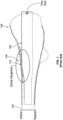
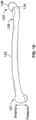
- FIG. 10 depicts an exemplary left leg femur.
- the femur has a proximal femur 120, distal femur 121, and femoral shaft 122 that extends between the proximal and distal femurs 120, 121.
- Proximal femur 120 includes a greater trochanter 124 and femoral head 126.
- femoral shaft 122 has an anterior bow such that the femur curves anteriorly in an anteroposterior extending plane. However, such curvature does not extend into proximal femur 120 which results in a slight posterior curvature or transitional bend 128 where femoral shaft 122 and proximal femur join 120.
- FIG. 1 depicts an exemplary prior art femoral nail 100 implanted within a femur, such as the femur in FIG. 10 , in an antegrade manner.
- the construction of femoral nail 100 is such that it has a portion 110 that impinges on the anterior cortex of the femur at transitional bend 128 between femoral shaft 122 and proximal femur 120.
- Such impingement may be caused by an underestimation of the curvature of the femur and, as illustrated in FIG. 1 , may occur at transitional bend 128 which is a location at or near the transition or necking down of the proximal femur 120 to the femoral shaft 122.
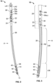
- FIGs. 2-7 depict a femoral nail 10 according to an embodiment of the present disclosure.
- Femoral nail 10 configured for implantation in a left leg and generally includes a proximal section 20, a distal section 28 and an intermediate section therebetween.
- the intermediate section includes a first curved portion 22, a straight portion 24, and a second curved portion 26.
- proximal section 20 and distal section 28 are each substantially straight along their respective lengths.
- Distal section 28 terminates at a distal tip 14 which defines a distal end of nail 10.
- Proximal section 20 is generally cylindrical and defines a longitudinal axis LA1 that extends along its length.
- Proximal section 20 defines a proximal end 12 of nail 10 which is configured to be coupled to an alignment/aiming instrument, such as by a threaded connection.
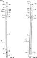
- An example of an aiming instrument is disclosed in U.S. Patent No. 6,039,739 . Also, as best shown in FIGs.
- the second set of screw holes which extend through the distal section of nail, include static screw holes 40, a compression screw hole 42, and a transverse screw hole 44.
- Static screw holes 40 and compression screw hole 42 each extend through distal section 28 and define screw hole axes that are perpendicular to a longitudinal axis of distal section 28 and lie within the Recon Plane, as best shown in FIG. 4 .
- Transverse screw hole 44 extends through distal portion 28 transverse to screw holes 40a-b and 44 and has an axis that is perpendicular to the longitudinal axis of distal section and lies within a plane which itself extends in a direction A, as shown in FIG. 3 . Such plane is referred to herein as a first plane or radius of center plane ("ROC Plane”), as is described in more detail below.
- transverse screw hole 44 is situated between static screw holes 40 along with compression screw hole 42.
- a bore 20 extends through proximal end 12 of nail 10 along its length and through distal tip 14.
- Proximal section 20 is internally threaded along a portion of the length of bore 20 adjacent the proximal end 12. Such internal threading is configured to mate with an alignment/aiming instrument and setscrew or cap, for example.
- second curved portion 26 is curved/bent in only the ROC Plane.
- second curved portion 26 may be curved/bent in other planes transverse to the ROC Plane as desired to match a patient(s) anatomy.
- First curved portion 22 is shorter in length than second curved portion 26 and has a first radius of curvature R1 of about 30 to 50 mm as depicted in FIG. 5 .
- first curved portion 22 is curved/bent in three separate, intersecting planes. More specifically, first curved portion 22 is curved/bent in the first plane or ROC Plane, as shown in FIGs. 2 and 3 .
- First curved portion 22 is also curved/bent in a second plane or Recon plane that extends in a direction B, as depicted in FIG. 4 .
- first curved portion 22 is curved/bent in a third plane that extends in a direction C, as best shown in FIG. 5 .
- the bends/curves in each of these planes define a radius of curvature of the first curved portion 22. Radius of curvature R1, which is mentioned above, lies in the third plane.
- first curved portion 22 in each of the first, second, and third planes has the effect of orienting longitudinal axis LA2 of straight portion 24 relative to longitudinal axis LA1 of proximal section 20 at first, second, and third angles 01, 02, and 03 within those respective planes.
- axis LA2 is angled relative to axis LA1 in the ROC Plane by a first bend angle ⁇ 1, in the Recon Plane by as second bend angle 02, and in a Resultant Bend Plane by a third bend angle 03, as shows in FIGs. 2 , 4, and 5 , respectively.
- bend angles 01, 02, and 03 differ in magnitude.
- bend angles 01, 02, and ⁇ 3 may be equal in each of the three planes. Where bend angles differ, third bend angle ⁇ 3 is a resultant of the first and second bend angles ⁇ 1 and 02.
- the magnitude of ⁇ 3 and the orientation of the Resultant Bend Plane relative to the other planes are a function of ⁇ 1 and ⁇ 2 and the angular orientation between the ROC Plane and Recon Plane in which such first and second bends respectively lie.
- first bend angle ⁇ 1 is preferably 3 degrees in the ROC Plane
- second bend angle ⁇ 2 is preferably 4 degrees in the Recon Plane where the ROC Plane and Recon Planes are oriented at an oblique angle ⁇ which is preferably 100 degrees, as best shown in FIG. 6 .
- third bend angle is about 4.5 degrees and Resultant Bend Plane is oriented about 59 degrees relative to ROC Plane and 41 degrees relative to Recon Plane
- angle ⁇ may be between 80 and 120 degrees
- first bend angle ⁇ 1 may be between 1.5 and 4.5 degrees
- second bend angle ⁇ 2 may be between 3 and 6 degrees
- third bend angle ⁇ 3 may be between 3 and 8 degrees.
- Such angles have been determined to suitably fit 95% of the patient population without the femoral cortex impingement described above based on a database analysis of a diverse population of bones.
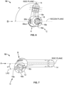
- FIG. 8 schematically illustrates the above described multi-planar bends/curves of first curved portion to help visualize the bends and how such bends are related to other structural features of nail 10, such as proximal notches 16a-c.
- first curved portion 22 bends in the ROC Plane at bend angle ⁇ 1 from axis LA2 of straight portion 24.
- First curved portion 22 also bends in the Recon Plane from axis LA2 at bend angle ⁇ 2. This results in axis LA1 of proximal section 20 being angled relative to axis LA2 of straight section by an angle ⁇ 3 in the Resultant Bend Plane.
- a Cartesian coordinate system is established such that the z-axis extends generally in an anterior-posterior direction, the x-axis extends generally in a lateral-medial direction, and the y-axis extends generally in a superior-inferior direction with the origin being located at the interface between first curved portion 22 and straight portion 24.
- the origin may also be located anywhere from about 10% to 40% of the length of nail 10 measured from a proximal end thereof.
- the y-axis coincides with longitudinal axis LA2 of straight section 24 and also defines the intersection between the ROC Plane, Recon Plane, and Resultant Bend Plane.
- the multi-planar bend has the effect of orienting proximal section 20 anteriorly and medially relative to straight portion 24.
- proximal section 20 slopes posteriorly in the superior to inferior direction which results in a canting away of nail 10 from an anterior cortex of a femur at the common impingement area as illustrated in FIG. 1 . It also aligns proximal section 20 and intermediate section with the natural lateral-medial curve of a femur. It should be understood that these bends are mirrored for a right-legged femoral nail.
- ROC Plane is oriented relative to the Recon Plane in the Cartesian coordinate system by the obtuse angle ⁇ .
- the Recon Plane is oriented relative to the x-plane within the Cartesian coordinate system by ⁇ -90°.
- angle ⁇ is 100 degrees
- Recon Plane is angled relative to the x-plane by 10 degrees.
- This offset of the Recon Plane relative to the x-plane helps form the bend in the Resultant Bend Plane and happens to also be equal to the angle ⁇ 1.
- ⁇ 1 is the angle formed between the ROC Plane and a longitudinal axis LA3 which bisects notches 16a and 16c, as shown in FIG. 7 .
- an angle ⁇ 2 is formed between axis LA3 and Resultant Bend Plane.
- the angle between the ROC Plane and the Resultant Bend plane is equal to the sum of ⁇ 1 and ⁇ 2. Therefore, in the example provided above where ⁇ is 100 degrees, ⁇ 1 is 10 degrees, and ⁇ 2 is 49 degrees, the angle between the ROC Plane and Resultant Bend Plane is 59 degrees.
- FIG. 9 illustrates the above described effect on femoral cortex impingement of the multi-planar bends.
- nail 10 overlays prior art nail 100 and, as a result of bends of first curve portion 22, nail 10 cants away from the anterior cortex of the femur at the common impingement zone of prior art nail 100 thereby reducing the possibility of femoral cortex impingement.
- Femoral nail 10 may have alternative constructions to that described above while remaining within the scope of the invention.
- femoral nail 10 may not include a straight distal end 28.
- second curved portion 24 may define the distal end 14 of nail 10.
- second curved portion 26 may curve about its center of curvature from straight portion 24 all the way to distal tip 14 of femoral nail 10.
- distal section 28 may itself be curved/bent in one or more planes so that it has a different radius of curvature than that of second curved portion 26.
- proximal section 20 may also be curved/bent along its length in one or more planes.
- nail 10 may not include a straight portion 24 within the intermediate section.
- second curved portion 26 may then be positioned adjacent first curved portion 22 and may extend distally therefrom.
- intermediate section may include a first curved portion 22 with a first radius of curvature R1 that defines bends in three separate planes, and a second curved portion 26 extending distally from the first curved portion 22 and curved/bent about a center of curvature in at least one plane.
- the straight portion 24 may be absent, the advantages described above with regard to nail 10 may still be present.
- first curved portion 22 and second curved portion 26 are each curved/bent in the ROC Plane, this may not be the case in every embodiment. It is possible that first curved portion 22 may be curved bent in three separate planes where none of these planes are coincident with the plane in which second curved portion 26 is curved.
Landscapes
- Health & Medical Sciences (AREA)
- Orthopedic Medicine & Surgery (AREA)
- Life Sciences & Earth Sciences (AREA)
- Surgery (AREA)
- Medical Informatics (AREA)
- Engineering & Computer Science (AREA)
- Biomedical Technology (AREA)
- Heart & Thoracic Surgery (AREA)
- Nuclear Medicine, Radiotherapy & Molecular Imaging (AREA)
- Molecular Biology (AREA)
- Animal Behavior & Ethology (AREA)
- General Health & Medical Sciences (AREA)
- Public Health (AREA)
- Veterinary Medicine (AREA)
- Neurology (AREA)
- Surgical Instruments (AREA)
- Prostheses (AREA)
Claims (14)
- Femurnagel (10), aufweisend:einen proximalen Abschnitt (20), der so konfiguriert ist, dass er mit einem Eintreibewerkzeug in Eingriff kommen kann, um den Femurnagel (10) in einen Oberschenkelknochen einzutreiben;einen distalen Abschnitt (28), der vom proximalen Abschnitt (20) entfernt ist; undeinen Zwischenabschnitt, der zwischen dem proximalen Abschnitt (20) und dem distalen Abschnitt (28) angeordnet ist, wobei der Zwischenabschnitt einen ersten gebogenen Abschnitt (22) aufweist, der in drei Dimensionen so gebogen ist, dass eine erste Biegung des ersten gebogenen Abschnitts (22) in einer ersten Ebene liegt, eine zweite Biegung in einer zweiten Ebene liegt und eine dritte Biegung in einer dritten Ebene liegt, die erste und die zweite Ebene sich in einem schrägen Winkel relativ zueinander schneiden, wobei die dritte Biegung einen von Null verschiedenen Krümmungsradius in der dritten Ebene des ersten gebogenen Abschnitts (22) definiert, wobei der Zwischenabschnitt einen geraden Abschnitt (24) aufweist, wobei der erste gebogene Abschnitt (22) zwischen dem geraden Abschnitt (24) und dem proximalen Abschnitt (20) angeordnet ist,wobei der gerade Abschnitt (24) eine Längsachse (LA2) definiert, die sich über seine Länge erstreckt,wobei der proximale Abschnitt (20) eine Längsachse (LA1) definiert, die sich über seine Länge erstreckt,wobei der erste gebogene Abschnitt (22) so gebogen ist, dass eine Längsachse (LA2) des geraden Abschnitts (24) relativ zu einer Längsachse (LA1) des proximalen Abschnitts (20) unter einen dritten Biegewinkel (θ3) in der dritten Ebene orientiert ist,wobei der dritte Biegewinkel (θ3) zwischen 3 und 8 Grad liegt.
- Femurnagel (10) nach Anspruch 1, wobei der distale Abschnitt (28) gerade ist und eine Vielzahl von Durchgangslöchern (40, 42) aufweist, die sich durch den distalen Abschnitt (28) in einer Richtung quer zu einer Achse des distalen Abschnitts erstrecken.
- Femurnagel (10) nach Anspruch 1 oder 2, wobei die erste Ebene größer als 80 Grad und kleiner als 120 Grad relativ zur zweiten Ebene ist.
- Femurnagel (10) nach Anspruch 3, wobei die erste Ebene 100 Grad relativ zur zweiten Ebene beträgt.
- Femurnagel (10) nach Anspruch 3, wobei sich die erste Ebene in einer anteriorposterioren Richtung und die zweite Ebene im Wesentlichen in einer medial-lateralen Richtung erstreckt.
- Femurnagel (10) nach einem der vorhergehenden Ansprüche, wobei die erste Biegung 3 Grad relativ zu einer Längsachse (LA2) beträgt, die durch einen Schnittpunkt zwischen der ersten und zweiten Ebene definiert ist, und die zweite Biegung 4 Grad relativ zur Längsachse (LA2) beträgt.
- Femurnagel (10) nach Anspruch 6, wobei die dritte Biegung mehr als 4 Grad relativ zur Längsachse (LA2) beträgt.
- Femurnagel (10) nach einem der vorhergehenden Ansprüche, wobei der proximale Abschnitt (20) des Femurnagels (10) eine Vielzahl von Durchgangslöchern (30a, 30b, 30c, 32) aufweist, die sich durch ihn hindurch erstrecken, wobei mindestens ein erstes und ein zweites Durchgangsloch der Vielzahl von Durchgangslöchern (30a, 30b, 30c, 32) jeweils erste und zweite Durchgangslochachsen aufweisen, die in der zweiten Ebene liegen.
- Femurnagel (10) nach einem der vorhergehenden Ansprüche, wobei der proximale Abschnitt (20) mindestens ein Rotationsausrichtungsmerkmal zum Anzeigen einer Rotationsausrichtung des Femurnagels (10) relativ zu einem Femur aufweist, wobei das Rotationsausrichtungsmerkmal gegenüber der dritten Ebene um einen spitzen Winkel rotationsmäßig versetzt ist.
- Femurnagel (10) nach Anspruch 9, wobei der spitze Winkel weniger als 50 Grad beträgt.
- Femurnagel (10) nach Anspruch 10, wobei das Rotationsausrichtungsmerkmal eine Eingriffskerbe (16a-c) ist, die so konfiguriert ist, dass sie mit dem Eintreibewerkzeug in Eingriff kommen kann.
- Femurnagel (10) nach einem der vorhergehenden Ansprüche, wobei die dritte Ebene die zweite Ebene in einem spitzen Winkel von weniger als 50 Grad schneidet.
- Femurnagel (10) nach einem der vorhergehenden Ansprüche, wobei Krümmungen jeder der Biegungen ihre jeweiligen Krümmungen an einem gemeinsamen Ursprung beginnen.
- Femurnagel (10) nach einem der vorhergehenden Ansprüche, wobei der Zwischenabschnitt einen zweiten gebogenen Abschnitt (26) aufweist, der zwischen dem distalen Abschnitt (28) und dem geraden Abschnitt (24) angeordnet ist.
Applications Claiming Priority (1)
| Application Number | Priority Date | Filing Date | Title |
|---|---|---|---|
| US201862657279P | 2018-04-13 | 2018-04-13 |
Publications (2)
| Publication Number | Publication Date |
|---|---|
| EP3552568A1 EP3552568A1 (de) | 2019-10-16 |
| EP3552568B1 true EP3552568B1 (de) | 2025-04-23 |
Family
ID=66105236
Family Applications (1)
| Application Number | Title | Priority Date | Filing Date |
|---|---|---|---|
| EP19168725.0A Active EP3552568B1 (de) | 2018-04-13 | 2019-04-11 | Femurnagel mit verbesserter knochenangepasster geometrie |
Country Status (7)
| Country | Link |
|---|---|
| US (4) | US11013540B2 (de) |
| EP (1) | EP3552568B1 (de) |
| JP (1) | JP7554548B2 (de) |
| CN (1) | CN110368081B (de) |
| AU (1) | AU2019202538B2 (de) |
| CA (1) | CA3040291C (de) |
| ES (1) | ES3034064T3 (de) |
Families Citing this family (8)
| Publication number | Priority date | Publication date | Assignee | Title |
|---|---|---|---|---|
| US20220151664A1 (en) * | 2015-04-16 | 2022-05-19 | Texas Tech University System | Ankle (Tibio-Talar) Fusion Nail |
| US10932828B2 (en) * | 2018-01-25 | 2021-03-02 | Advanced Orthopaedic Solutions, Inc. | Bone nail |
| EP3552568B1 (de) * | 2018-04-13 | 2025-04-23 | Stryker European Operations Holdings LLC | Femurnagel mit verbesserter knochenangepasster geometrie |
| EP3626184A1 (de) * | 2018-09-21 | 2020-03-25 | OrthoXel DAC | Femurnagelsystem |
| JP7620648B2 (ja) | 2020-05-29 | 2025-01-23 | ストライカー・ユーロピアン・オペレーションズ・リミテッド | 髄内釘のための漏斗穴 |
| JP2024532849A (ja) | 2021-08-17 | 2024-09-10 | ペレス エドワード | 骨固定装置、システム、および方法 |
| US20240148417A1 (en) | 2022-11-07 | 2024-05-09 | Stryker European Operations Limited | Intermediate Femoral Nail |
| US20260033873A1 (en) | 2024-08-01 | 2026-02-05 | Stryker European Operations Limited | Intramedullary Nail |
Family Cites Families (39)
| Publication number | Priority date | Publication date | Assignee | Title |
|---|---|---|---|---|
| US3709218A (en) | 1970-04-24 | 1973-01-09 | W Halloran | Combination intramedullary fixation and external bone compression apparatus |
| US4133507A (en) | 1977-04-27 | 1979-01-09 | Comerco, Inc. | System for mounting storage units |
| US4135507A (en) | 1977-05-20 | 1979-01-23 | Harris Leslie J | Condylocephalic nail for fixation of pertrochanteric fractures |
| US4475545A (en) | 1982-12-06 | 1984-10-09 | Ender Hans G | Bone-nail |
| DE8620399U1 (de) | 1986-07-30 | 1986-10-09 | Howmedica GmbH Werk Schönkirchen, 2314 Schönkirchen | Osteosynthesehilfsmittel zur Versorgung subtrochanterer Frakturen |
| US5176681A (en) | 1987-12-14 | 1993-01-05 | Howmedica International Inc. | Intramedullary intertrochanteric fracture fixation appliance and fitting device |
| CH674797A5 (de) | 1988-02-29 | 1990-07-31 | Sulzer Ag | |
| CH674613A5 (de) | 1988-03-14 | 1990-06-29 | Synthes Ag | |
| US5066296A (en) | 1989-02-02 | 1991-11-19 | Pfizer Hopsital Products Group, Inc. | Apparatus for treating a fracture |
| GB9113578D0 (en) | 1991-06-24 | 1991-08-14 | Howmedica | Intramedullary intertrochanteric fracture fixation appliance |
| DE29615482U1 (de) | 1996-09-05 | 1998-01-08 | Howmedica GmbH, 24232 Schönkirchen | Suprakondylarer Knochennagel |
| DE29806564U1 (de) | 1998-04-09 | 1999-08-12 | Howmedica Gmbh | Zielgerät für einen Verriegelungsnagel |
| US6010506A (en) | 1998-09-14 | 2000-01-04 | Smith & Nephew, Inc. | Intramedullary nail hybrid bow |
| US6120504A (en) | 1998-12-10 | 2000-09-19 | Biomet Inc. | Intramedullary nail having dual distal bore formation |
| DE50015249D1 (de) * | 1999-05-12 | 2008-08-21 | Zimmer Gmbh | Verriegelungsnagel zur Versorgung von Femurschaftfrakturen |
| ATE321497T1 (de) | 1999-05-21 | 2006-04-15 | I T S Implantat Technologie Sy | Tibiamarknagel |
| DE59908678D1 (de) | 1999-12-03 | 2004-04-01 | Synthes Ag | Intramedullärer marknagel |
| US6210414B1 (en) | 2000-04-20 | 2001-04-03 | Chin Lin | Bone fastener for shinbone and thighbone |
| EP1260188B1 (de) | 2001-05-25 | 2014-09-17 | Zimmer GmbH | Oberschenkel-Marknagel zum Einbringen am Kniegelenk |
| US7947043B2 (en) | 2004-01-20 | 2011-05-24 | Depuy Products, Inc. | Intramedullary nail and associated method |
| US7771428B2 (en) * | 2004-06-11 | 2010-08-10 | Synthes Usa, Llc | Intramedullary rod with spiraling flutes |
| EP1639953B1 (de) | 2004-09-27 | 2008-05-21 | ORTHOFIX S.r.l. | Marknagel zur Behandlung von proximalen Oberschenkelknochenbrüchen |
| EP1802243B1 (de) * | 2004-10-14 | 2014-11-26 | Synthes GmbH | Marknagel zur einführung in den markraum eines femur |
| JP5060308B2 (ja) | 2004-12-31 | 2012-10-31 | シンセス ゲゼルシャフト ミット ベシュレンクテル ハフツング | 髄内釘 |
| RU2271768C1 (ru) | 2005-05-23 | 2006-03-20 | Общество с ограниченной ответственностью "ОСТЕОМЕД-М" (ООО "ОСТЕОМЕД-М") | Устройство бялика е.и., холявкина д.а., соколова в.а. для лечения сложных переломов бедренной кости |
| US20070123873A1 (en) * | 2005-10-31 | 2007-05-31 | Czartoski Timothy J | Intramedullary nail with oblique openings |
| US20070123874A1 (en) | 2005-10-31 | 2007-05-31 | Czartoski Timothy J | Multiple purpose nail with oblique openings |
| US8790343B2 (en) | 2008-10-11 | 2014-07-29 | Epix Orthopaedics, Inc. | Intramedullary rod with pivotable and fixed fasteners and method for using same |
| CN102639074B (zh) * | 2009-06-30 | 2016-03-16 | 史密夫和内修有限公司 | 整形外科的植入物和紧固组件 |
| GB0911697D0 (en) | 2009-07-06 | 2009-08-19 | Smith & Nephew | Methods and devices for monitoring fractures |
| US8540714B2 (en) | 2010-05-11 | 2013-09-24 | Orthopediatrics Corp. | Pediatric intramedullary nail |
| CN202105011U (zh) * | 2011-06-13 | 2012-01-11 | 张世民 | 一种带有前弓弧度的短型股骨头髓钉 |
| US9220544B2 (en) | 2011-12-15 | 2015-12-29 | Epix Orthopaedics, Inc. | Implantable device with locking adjustment mechanism and method for using same |
| JP2012130724A (ja) | 2012-02-20 | 2012-07-12 | Homuzu Giken:Kk | 髄内釘及び整形外科手術器具セット |
| US9936989B2 (en) | 2013-10-22 | 2018-04-10 | General Surgical Company (India) Pvt Limited | Device for bone support with improved rotational stability |
| JP6847096B2 (ja) | 2015-05-22 | 2021-03-24 | ストライカー ヨーロピアン ホールディングス I,エルエルシーStryker European Holdings I,Llc | 骨固定用インプラントシステム |
| EP3552568B1 (de) * | 2018-04-13 | 2025-04-23 | Stryker European Operations Holdings LLC | Femurnagel mit verbesserter knochenangepasster geometrie |
| WO2021176272A1 (en) | 2020-03-06 | 2021-09-10 | Stryker European Operations Limited | Set screw for femoral nail |
| EP4114294A1 (de) | 2020-03-06 | 2023-01-11 | Stryker European Operations Limited | Stellschraube für femurnagel |
-
2019
- 2019-04-11 EP EP19168725.0A patent/EP3552568B1/de active Active
- 2019-04-11 AU AU2019202538A patent/AU2019202538B2/en active Active
- 2019-04-11 US US16/381,453 patent/US11013540B2/en active Active
- 2019-04-11 ES ES19168725T patent/ES3034064T3/es active Active
- 2019-04-12 CA CA3040291A patent/CA3040291C/en active Active
- 2019-04-12 JP JP2019076248A patent/JP7554548B2/ja active Active
- 2019-04-15 CN CN201910300837.0A patent/CN110368081B/zh active Active
-
2021
- 2021-04-13 US US17/228,806 patent/US11730525B2/en active Active
-
2023
- 2023-06-30 US US18/216,803 patent/US12310636B2/en active Active
-
2025
- 2025-05-06 US US19/199,972 patent/US20250325309A1/en active Pending
Also Published As
| Publication number | Publication date |
|---|---|
| US20250325309A1 (en) | 2025-10-23 |
| CN110368081B (zh) | 2022-09-30 |
| US11730525B2 (en) | 2023-08-22 |
| US20210228247A1 (en) | 2021-07-29 |
| EP3552568A1 (de) | 2019-10-16 |
| US20230338069A1 (en) | 2023-10-26 |
| AU2019202538B2 (en) | 2024-02-29 |
| JP2019205824A (ja) | 2019-12-05 |
| CN110368081A (zh) | 2019-10-25 |
| CA3040291C (en) | 2023-03-28 |
| US20190314065A1 (en) | 2019-10-17 |
| US11013540B2 (en) | 2021-05-25 |
| CA3040291A1 (en) | 2019-10-13 |
| US12310636B2 (en) | 2025-05-27 |
| ES3034064T3 (en) | 2025-08-12 |
| JP7554548B2 (ja) | 2024-09-20 |
| AU2019202538A1 (en) | 2019-10-31 |
Similar Documents
| Publication | Publication Date | Title |
|---|---|---|
| US12310636B2 (en) | Femoral nail with enhanced bone conforming geometry | |
| US6096040A (en) | Upper extremity bone plates | |
| JP5702290B2 (ja) | 髄内釘 | |
| US9427267B2 (en) | Method for tibial nail insertion | |
| EP0355411A1 (de) | Intramedullärer Stift zur Oberschenkelknochenfestigung | |
| US6572620B1 (en) | Modular, blade-rod, intramedullary fixation device | |
| US8808334B2 (en) | Orthopedic plate | |
| EP3600069B1 (de) | Knochenfixationssysteme und insertionsführungen | |
| WO1997047251A9 (en) | Upper extremity bone plate | |
| EP3013264B1 (de) | Mediales distales femurknochenplattensystem | |
| US20240268872A1 (en) | Clavicle segmental plate system | |
| JPS58103443A (ja) | 骨釘 | |
| AU2019204554B2 (en) | Phalangeal head plate | |
| CN213665664U (zh) | 一种肱骨近端大结节锁定板 | |
| EP4454582B1 (de) | Knochenplatte zur sicherung eines gebrochenen knochens | |
| CN117982216A (zh) | 中型股骨髓内钉 | |
| WO2025122702A1 (en) | Veterinary proximal femur fracture plates | |
| JP2023021887A5 (ja) | 股関節手術用補助具 |
Legal Events
| Date | Code | Title | Description |
|---|---|---|---|
| PUAI | Public reference made under article 153(3) epc to a published international application that has entered the european phase |
Free format text: ORIGINAL CODE: 0009012 |
|
| STAA | Information on the status of an ep patent application or granted ep patent |
Free format text: STATUS: REQUEST FOR EXAMINATION WAS MADE |
|
| 17P | Request for examination filed |
Effective date: 20190411 |
|
| AK | Designated contracting states |
Kind code of ref document: A1 Designated state(s): AL AT BE BG CH CY CZ DE DK EE ES FI FR GB GR HR HU IE IS IT LI LT LU LV MC MK MT NL NO PL PT RO RS SE SI SK SM TR |
|
| AX | Request for extension of the european patent |
Extension state: BA ME |
|
| STAA | Information on the status of an ep patent application or granted ep patent |
Free format text: STATUS: EXAMINATION IS IN PROGRESS |
|
| 17Q | First examination report despatched |
Effective date: 20201126 |
|
| RAP1 | Party data changed (applicant data changed or rights of an application transferred) |
Owner name: STRYKER EUROPEAN OPERATIONS HOLDINGS LLC |
|
| GRAP | Despatch of communication of intention to grant a patent |
Free format text: ORIGINAL CODE: EPIDOSNIGR1 |
|
| STAA | Information on the status of an ep patent application or granted ep patent |
Free format text: STATUS: GRANT OF PATENT IS INTENDED |
|
| INTG | Intention to grant announced |
Effective date: 20241104 |
|
| RAP3 | Party data changed (applicant data changed or rights of an application transferred) |
Owner name: STRYKER EUROPEAN OPERATIONS HOLDINGS LLC |
|
| GRAS | Grant fee paid |
Free format text: ORIGINAL CODE: EPIDOSNIGR3 |
|
| GRAA | (expected) grant |
Free format text: ORIGINAL CODE: 0009210 |
|
| STAA | Information on the status of an ep patent application or granted ep patent |
Free format text: STATUS: THE PATENT HAS BEEN GRANTED |
|
| AK | Designated contracting states |
Kind code of ref document: B1 Designated state(s): AL AT BE BG CH CY CZ DE DK EE ES FI FR GB GR HR HU IE IS IT LI LT LU LV MC MK MT NL NO PL PT RO RS SE SI SK SM TR |
|
| P01 | Opt-out of the competence of the unified patent court (upc) registered |
Free format text: CASE NUMBER: APP_12468/2025 Effective date: 20250313 |
|
| REG | Reference to a national code |
Ref country code: GB Ref legal event code: FG4D |
|
| REG | Reference to a national code |
Ref country code: CH Ref legal event code: EP |
|
| REG | Reference to a national code |
Ref country code: DE Ref legal event code: R096 Ref document number: 602019068920 Country of ref document: DE |
|
| REG | Reference to a national code |
Ref country code: IE Ref legal event code: FG4D |
|
| REG | Reference to a national code |
Ref country code: ES Ref legal event code: FG2A Ref document number: 3034064 Country of ref document: ES Kind code of ref document: T3 Effective date: 20250812 |
|
| REG | Reference to a national code |
Ref country code: NL Ref legal event code: MP Effective date: 20250423 |
|
| PG25 | Lapsed in a contracting state [announced via postgrant information from national office to epo] |
Ref country code: NL Free format text: LAPSE BECAUSE OF FAILURE TO SUBMIT A TRANSLATION OF THE DESCRIPTION OR TO PAY THE FEE WITHIN THE PRESCRIBED TIME-LIMIT Effective date: 20250423 |
|
| REG | Reference to a national code |
Ref country code: AT Ref legal event code: MK05 Ref document number: 1787026 Country of ref document: AT Kind code of ref document: T Effective date: 20250423 |
|
| PG25 | Lapsed in a contracting state [announced via postgrant information from national office to epo] |
Ref country code: FI Free format text: LAPSE BECAUSE OF FAILURE TO SUBMIT A TRANSLATION OF THE DESCRIPTION OR TO PAY THE FEE WITHIN THE PRESCRIBED TIME-LIMIT Effective date: 20250423 Ref country code: PT Free format text: LAPSE BECAUSE OF FAILURE TO SUBMIT A TRANSLATION OF THE DESCRIPTION OR TO PAY THE FEE WITHIN THE PRESCRIBED TIME-LIMIT Effective date: 20250825 |
|
| REG | Reference to a national code |
Ref country code: LT Ref legal event code: MG9D |
|
| PG25 | Lapsed in a contracting state [announced via postgrant information from national office to epo] |
Ref country code: GR Free format text: LAPSE BECAUSE OF FAILURE TO SUBMIT A TRANSLATION OF THE DESCRIPTION OR TO PAY THE FEE WITHIN THE PRESCRIBED TIME-LIMIT Effective date: 20250724 Ref country code: NO Free format text: LAPSE BECAUSE OF FAILURE TO SUBMIT A TRANSLATION OF THE DESCRIPTION OR TO PAY THE FEE WITHIN THE PRESCRIBED TIME-LIMIT Effective date: 20250723 |
|
| PG25 | Lapsed in a contracting state [announced via postgrant information from national office to epo] |
Ref country code: PL Free format text: LAPSE BECAUSE OF FAILURE TO SUBMIT A TRANSLATION OF THE DESCRIPTION OR TO PAY THE FEE WITHIN THE PRESCRIBED TIME-LIMIT Effective date: 20250423 |
|
| PG25 | Lapsed in a contracting state [announced via postgrant information from national office to epo] |
Ref country code: BG Free format text: LAPSE BECAUSE OF FAILURE TO SUBMIT A TRANSLATION OF THE DESCRIPTION OR TO PAY THE FEE WITHIN THE PRESCRIBED TIME-LIMIT Effective date: 20250423 |
|
| PG25 | Lapsed in a contracting state [announced via postgrant information from national office to epo] |
Ref country code: HR Free format text: LAPSE BECAUSE OF FAILURE TO SUBMIT A TRANSLATION OF THE DESCRIPTION OR TO PAY THE FEE WITHIN THE PRESCRIBED TIME-LIMIT Effective date: 20250423 |
|
| PG25 | Lapsed in a contracting state [announced via postgrant information from national office to epo] |
Ref country code: AT Free format text: LAPSE BECAUSE OF FAILURE TO SUBMIT A TRANSLATION OF THE DESCRIPTION OR TO PAY THE FEE WITHIN THE PRESCRIBED TIME-LIMIT Effective date: 20250423 |
|
| PG25 | Lapsed in a contracting state [announced via postgrant information from national office to epo] |
Ref country code: RS Free format text: LAPSE BECAUSE OF FAILURE TO SUBMIT A TRANSLATION OF THE DESCRIPTION OR TO PAY THE FEE WITHIN THE PRESCRIBED TIME-LIMIT Effective date: 20250723 |
|
| PG25 | Lapsed in a contracting state [announced via postgrant information from national office to epo] |
Ref country code: IS Free format text: LAPSE BECAUSE OF FAILURE TO SUBMIT A TRANSLATION OF THE DESCRIPTION OR TO PAY THE FEE WITHIN THE PRESCRIBED TIME-LIMIT Effective date: 20250823 |
|
| PG25 | Lapsed in a contracting state [announced via postgrant information from national office to epo] |
Ref country code: LV Free format text: LAPSE BECAUSE OF FAILURE TO SUBMIT A TRANSLATION OF THE DESCRIPTION OR TO PAY THE FEE WITHIN THE PRESCRIBED TIME-LIMIT Effective date: 20250423 |
|
| PG25 | Lapsed in a contracting state [announced via postgrant information from national office to epo] |
Ref country code: DK Free format text: LAPSE BECAUSE OF FAILURE TO SUBMIT A TRANSLATION OF THE DESCRIPTION OR TO PAY THE FEE WITHIN THE PRESCRIBED TIME-LIMIT Effective date: 20250423 Ref country code: SM Free format text: LAPSE BECAUSE OF FAILURE TO SUBMIT A TRANSLATION OF THE DESCRIPTION OR TO PAY THE FEE WITHIN THE PRESCRIBED TIME-LIMIT Effective date: 20250423 |
|
| PG25 | Lapsed in a contracting state [announced via postgrant information from national office to epo] |
Ref country code: CZ Free format text: LAPSE BECAUSE OF FAILURE TO SUBMIT A TRANSLATION OF THE DESCRIPTION OR TO PAY THE FEE WITHIN THE PRESCRIBED TIME-LIMIT Effective date: 20250423 |
|
| PG25 | Lapsed in a contracting state [announced via postgrant information from national office to epo] |
Ref country code: EE Free format text: LAPSE BECAUSE OF FAILURE TO SUBMIT A TRANSLATION OF THE DESCRIPTION OR TO PAY THE FEE WITHIN THE PRESCRIBED TIME-LIMIT Effective date: 20250423 |
|
| PG25 | Lapsed in a contracting state [announced via postgrant information from national office to epo] |
Ref country code: RO Free format text: LAPSE BECAUSE OF FAILURE TO SUBMIT A TRANSLATION OF THE DESCRIPTION OR TO PAY THE FEE WITHIN THE PRESCRIBED TIME-LIMIT Effective date: 20250423 Ref country code: SK Free format text: LAPSE BECAUSE OF FAILURE TO SUBMIT A TRANSLATION OF THE DESCRIPTION OR TO PAY THE FEE WITHIN THE PRESCRIBED TIME-LIMIT Effective date: 20250423 |