EP3552560A1 - Ligation clip with latching and retention features - Google Patents
Ligation clip with latching and retention features Download PDFInfo
- Publication number
- EP3552560A1 EP3552560A1 EP19168517.1A EP19168517A EP3552560A1 EP 3552560 A1 EP3552560 A1 EP 3552560A1 EP 19168517 A EP19168517 A EP 19168517A EP 3552560 A1 EP3552560 A1 EP 3552560A1
- Authority
- EP
- European Patent Office
- Prior art keywords
- jaw
- ligation clip
- protrusions
- bosses
- spaced
- Prior art date
- Legal status (The legal status is an assumption and is not a legal conclusion. Google has not performed a legal analysis and makes no representation as to the accuracy of the status listed.)
- Granted
Links
Images


Classifications
-
- A—HUMAN NECESSITIES
- A61—MEDICAL OR VETERINARY SCIENCE; HYGIENE
- A61B—DIAGNOSIS; SURGERY; IDENTIFICATION
- A61B17/00—Surgical instruments, devices or methods
- A61B17/12—Surgical instruments, devices or methods for ligaturing or otherwise compressing tubular parts of the body, e.g. blood vessels or umbilical cord
- A61B17/122—Clamps or clips, e.g. for the umbilical cord
-
- A—HUMAN NECESSITIES
- A61—MEDICAL OR VETERINARY SCIENCE; HYGIENE
- A61B—DIAGNOSIS; SURGERY; IDENTIFICATION
- A61B17/00—Surgical instruments, devices or methods
- A61B17/12—Surgical instruments, devices or methods for ligaturing or otherwise compressing tubular parts of the body, e.g. blood vessels or umbilical cord
- A61B17/122—Clamps or clips, e.g. for the umbilical cord
- A61B17/1227—Spring clips
-
- A—HUMAN NECESSITIES
- A61—MEDICAL OR VETERINARY SCIENCE; HYGIENE
- A61B—DIAGNOSIS; SURGERY; IDENTIFICATION
- A61B17/00—Surgical instruments, devices or methods
- A61B17/12—Surgical instruments, devices or methods for ligaturing or otherwise compressing tubular parts of the body, e.g. blood vessels or umbilical cord
- A61B17/128—Surgical instruments, devices or methods for ligaturing or otherwise compressing tubular parts of the body, e.g. blood vessels or umbilical cord for applying or removing clamps or clips
-
- A—HUMAN NECESSITIES
- A61—MEDICAL OR VETERINARY SCIENCE; HYGIENE
- A61M—DEVICES FOR INTRODUCING MEDIA INTO, OR ONTO, THE BODY; DEVICES FOR TRANSDUCING BODY MEDIA OR FOR TAKING MEDIA FROM THE BODY; DEVICES FOR PRODUCING OR ENDING SLEEP OR STUPOR
- A61M39/00—Tubes, tube connectors, tube couplings, valves, access sites or the like, specially adapted for medical use
- A61M39/22—Valves or arrangement of valves
- A61M39/28—Clamping means for squeezing flexible tubes, e.g. roller clamps
- A61M39/284—Lever clamps
Definitions
- the present disclosure is directed to ligation clips for sealing body vessels and, more particularly, to ligation clips that include applicator engagement structure to more securely support the ligation clips on a surgical clip applicator.
- Ligation clips are well known in the surgical arts and are commonly used during a variety of surgical procedures to ligate tissue, e.g., a body vessel.
- Ligation clips include first and second jaws that are pivotably coupled to each other such that the ligation clip is movable between an open position and a clamped position.
- each of the first and second jaws includes bosses that are configured to engage jaws of a clip applicator to support the ligation clip on the clip applicator.
- the jaws of the clip applicator include recesses that receive the bosses to support the ligation clip on the clip applicator to facilitate placement of the ligation clip about body tissue.
- the jaws of the clip applicator are movable between open and clamped positions to move the ligation clip between the open and clamped positions.
- the bosses on the first and second jaws of the ligation clips and the recesses on the jaws of the clip applicator are not configured to securely fasten the ligation clip on the clip applicator.
- the ligation clip it is not unusual for the ligation clip to become dislodged from the clip applicator and fall into a body cavity as the clip applicator is maneuvered around tissue during placement of the ligation clip.
- the clinician must remove the clip applicator from the body cavity, retrieve the ligation clip from the body cavity, and place a new ligation clip onto the jaws of the clip applicator. This process is time consuming and wasteful.
- a ligation clip including a first jaw, and a second jaw.
- the first jaw includes a body defining a first clamping surface and supporting a first pair of spaced bosses.
- the second jaw includes a body defining a second clamping surface.
- the second jaw is coupled to the first jaw such that the ligation clip is movable between an open position and a clamped position.
- the second jaw supports a second pair of spaced bosses.
- Each of the bosses of the first and second pairs of bosses includes a transverse portion and a head portion.
- the transverse portion extends outwardly of the body of the respective first or second jaw.
- the head portion is supported on the transverse portion outwardly of the body of the respective first or second jaw.
- the diameter of the head portion is greater than the diameter of the transverse portion to define a shoulder between the transverse portion and the head portion.
- each of the bosses of the first and second pairs of spaced bosses are cylindrical.
- each of the bosses of the first and second pairs of spaced bosses are formed by a single member that extends between the head portions of the first and second pairs of spaced bosses.
- the first jaw includes a longitudinal rib having a tissue engaging surface that is positioned in opposition to the second clamping surface of the second jaw when the ligation clip is in the clamped position.
- the second jaw has a first row of protrusions supported on one side of the second clamping surface and a second row of protrusions supported on an opposite side of the second clamping surface.
- each of the protrusions of the first and second rows of protrusions has an inner side wall in opposition to the longitudinal rib when the ligation clip is in the clamped position.
- the first row of protrusions is laterally spaced from the second row of protrusions to define a channel that extends longitudinally between the first and second rows of protrusions, wherein the channel is positioned to receive the stepped longitudinal rib when the ligation clip is in the clamped position.
- the protrusions in the first row of protrusions are longitudinally aligned and spaced from each other and the protrusions in the second row of protrusions are longitudinally aligned and spaced from each other.
- each of the protrusions in the first row of protrusions are longitudinally offset from each of the protrusions in the second row of protrusions such that the protrusions are alternatingly positioned on opposite sides of the second clamping surface along the length of the second clamping surface.
- the first jaw includes a first locking element and the second jaw includes a second locking element, wherein the first locking element is movable into engagement with the second locking element to retain the ligation clip in the clamped position.
- the ligation clip is formed of a polymeric material.
- the second jaw includes a distal portion including spaced teeth that are configured to penetrate tissue.
- the first locking element includes a hooked portion that extends downwardly and proximally from the first tissue clamping surface and the second locking element defines an engagement surface for receiving the hooked portion.
- the second locking element defines a cam surface that engages the hooked portion to bias the hooked portion outwardly of the second locking element such that the hooked portion resiliently returns to an unbiased state after passing over the second locking element to position the hooked portion in contact with the engagement surface.
- the second jaw includes a spring arm that is positioned to engage and be deflected by the first locking element as the ligation clip is moved from the open position to the clamped position, wherein the spring arm is positioned to urge the first and second locking elements to a latched position.
- proximal is used generally to refer to that portion of the device that is closer to a clinician
- distal is used generally to refer to that portion of the device that is farther from the clinician
- clinician is used generally to refer to medical personnel including doctors, nurses, and support personnel.
- the ligation clip 10 defines a longitudinal axis "Z" ( FIG. 2A ) and includes a first jaw 12, a second jaw 14, and a hinge portion 16 coupling the first jaw 12 to the second jawl4.
- the first jaw 12 is pivotable in relation to the second jaw 14 about the hinge portion 16 to move the ligation clip 10 between an open position ( FIG. 1 ) and a clamped position ( FIG. 3 ).
- the first and second jaws 12, 14 are curved along the longitudinal axis "Z" ( FIG. 6 ) although other jaw configurations are envisioned.
- the hinge portion 16 may be integrally formed with the first and second jaws 12, 14, e.g., a living hinge, and may define a crescent shaped through bore 16a to facilitate movement of the first jaw 12 in relation to the second jaw 14 between the open and clamped positions.
- the through bore 16a also allows for substantially complete closure of the proximal portions of the first and second jaws 12, 14.
- the first jaw 12 has a body 12a having a proximal portion 18, a distal portion 20, and a clamping surface 22.
- the second jaw 14 has a body 14a having a proximal portion 24, a distal portion 26, and a clamping surface 28.
- the proximal portions 18, 24 of the first and second jaws 12, 14, respectively, are coupled to the hinge portion 16 such that the ligation clip 10 is pivotable between an open position ( FIG. 1 ) and a clamped position ( FIG. 2 ).
- the distal portion 20 of the first jaw 12 includes a first locking element 30 and engagement structure 31 including spaced bosses 32.
- the first locking element 30 includes a hooked portion 30a that extends downwardly and proximally from the tissue clamping surface 22 to define a portion of a latching mechanism 34 ( FIG. 2A ) that is configured to retain the ligation clip 10 in a clamped position as described in further detail below.
- the engagement structure 31 of the first jaw 12 including the bosses 32 are supported on the distal portion of the body 12a of the first jaw 12.
- Each of the bosses 32 includes a transverse portion 36 that extends outwardly of the body 12a of the first jaw 12 and a head portion 38 that is supported on the transverse portion 38 outwardly of the body 12a of the first jaw 12.
- the head portion 38 has a diameter or width, collectively referred to herein as "diameter”, that is greater than the diameter of the transverse portion 36 to define a shoulder 38a between the transverse portion 36 and the head portion 38.
- the transverse portion 36 and/or the head portion 38 of the bosses 32 is cylindrical although other configurations are envisioned.
- the transverse portion 36 of the bosses 32 may form part of a single member supported on the distal portion of the first jaw 12 that extends between the head portions 38 of the spaced bosses 32.
- the head portions 38 of the bosses 32 are positioned outwardly from the body 12a of the first jaw 12 such that the transverse portion 36 are accessible to jaws 114, 116 of a clip applicator 100 ( FIG. 8 ) as described in further detail below to facilitate placement of the ligation clip 10 on the clip applicator 100.
- the distal portion 26 of the second jaw 14 includes a second locking element 40, engagement structure 41 including spaced bosses 42, and spaced teeth 44.
- the spaced teeth 44 are configured to engage and/or penetrate tissue.
- the teeth 44 have an apex or pointed end 44a that grips and stretches tissue as the ligation clip 10 is moved from the open position ( FIG. 1 ) towards the clamped position ( FIG. 2 ) to improve the ligating characteristics of the ligation clip 10.
- the second locking element 40 defines an engagement surface 46 ( FIG. 2A ) and a cam surface 48.
- the cam surface 48 and the engagement surface 46 are configured to receive and guide the first locking element 30 into locking engagement with the second locking element 40 when the ligation clip 10 is moved to the clamped position ( FIG.
- the cam surface 48 is configured to deflect the first locking element 30 outwardly in a distal direction as the first locking element 30 passes over the cam surface 48 such that when the first locking element 30 moves past the cam surface 48, the first locking element 30 resiliently moves into engagement with the second locking element 40 ( FIG. 2A ).
- the bosses 42 of the engagement structure 41( FIG. 2 ) of the second jaw 14 are similar to the bosses 32 of the first jaw 12. More specifically, the bosses 42 each include a transverse portion 50 and a head portion 52. In embodiments, the head portion has a flat surface 52a that faces the spaced bosses 42. The head portion 52 has a diameter that is greater than the diameter of the transverse portion 50 to define a shoulder 52b between the transverse portion 50 and the head portion 52. In embodiments, the transverse portion 50 and/or the head portion 52 of the bosses 42 is cylindrical although other configurations are envisioned, e.g., square, triangular, etc.
- each of the bosses 52 may form part of a single member supported on the distal portion of the second jaw 14 that extends between the spaced bosses 42.
- the head portions 50 of the bosses 42 are positioned outwardly from the body 14a of the second jaw 14 such that the transverse portions 50 of the bosses 42 are accessible to the jaws 114, 116 of the clip applicator 100 ( FIG. 8 ) to facilitate placement of the ligation clip 10 on the clip applicator 100 as described in further detail below.
- the second jaw 14 includes a spring arm 56 that is positioned to engage the first locking element 30 when the ligation element 10 is moved to the clamped position to retain the first locking element 30 and the second element 40 in the latched position ( FIG. 2A ).
- the spring arm 56 is positioned to engage and be deflected by the first locking element 30 to create a compressive force within the spring arm 56 that presses against the second locking element.
- the first clamping surface 22 is substantially flat and supports a longitudinal rib 60 ( FIG. 4 ) including a tissue engaging surface 62 that is in opposition with the clamping surface 28 of the second jaw 14 when the ligation clip 10 is in the clamped position ( FIG. 3 ).
- the longitudinal rib 60 is rectangular although other rib configurations are envisioned.
- the tissue engaging surface 62 of the longitudinal rib 60 is substantially flat and extends substantially the entire length of the tissue clamping surface 22.
- the longitudinal rib 60 may include one or more longitudinal rib sections that are longitudinally spaced from each other and extend over a length less than the entire length of the tissue clamping surface 22, e.g., 50-80 percent of the length of the tissue clamping surface 22.
- the second clamping surface 28 is substantially flat and supports a first row of protrusions 70a and a second row of protrusions 70b.
- Each of the protrusions 70a of the first row of protrusions 70a is spaced from but longitudinally aligned with each of the other protrusions 70a in the first row along a first side of the second clamping surface 28.
- each of the protrusions 70b of the second row of protrusions 70b is longitudinally aligned with each of the other protrusions 70b in the second row along a second side of the second clamping surface 28 opposite to the first side.
- the protrusions 70a, 70b may have a width that is less than half the width of the clamping surface 28 to define an unobstructed central channel 71 between the first and second rows of protrusions 70a, 70b on the second clamping surface 28.
- the central channel 71 is receives the longitudinal rib 60 when the ligation clip 10 is in the clamped position.
- each of the protrusions 70a on the first side of the clamping surface 28 is longitudinally offset from each of protrusions 70b positioned on the other side of the clamping surface 28 such that the protrusions 70a and 70b are alternatingly positioned on opposite sides of the clamping surface 28 along the length of the clamping surface 28.
- Each of the protrusions 70a, 70b includes a tissue engaging surface 72 ( FIG. 4A ) and an inner side wall 74.
- the tissue engaging surface 72 is positioned in opposition to the clamping surface 22 of the first jaw 12 when the ligation clip 10 is in the clamped position.
- the inner side wall 74 of each of the protrusions 70a, 70b is positioned in opposition to the longitudinal rib 60 when the ligation clip 10 is in the clamped position ( FIG. 2A ).
- the surgical ligation clip 10 may be made, in whole or in part, of a resilient bioabsorbable and/or biocompatible polymeric material.
- suitable bioabsorbable and/or biocompatible polymers include acetal polyoxymethylene (POM), polyethylene terephthalate (PET), polybutylene terephthalate (PBT), polyoxymethylene, polyetheretherketone (PEEK), polypropylene, and polyethylene or other thermoplastic materials having similar properties that can be injection-molded.
- the clip may also be made of a polymer material or materials in combination with radiolucent metal alloys. Alternately, other materials may be used to form the clip 10 including biocompatible metals, plastics and composites.
- the ligation clip 10 is placed about tissue "T", e.g., a body vessel, such that the tissue "T” is positioned between the tissue clamping surface 22 of the first jaw 12 and the tissue clamping surface 28 of the second jaw 14.
- tissue "T” is compressed between the first and second clamping surfaces 22, 28 of the first and second jaws 12, 14, and between the longitudinal rib 60 of the first jaw 12 and the protrusions 70a, 70b of the second jaw 14.
- the above described ligation clip 10 including a first jaw 12 having a longitudinal rib 60 and a second jaw 14 including first and second rows of protrusions 70a, 70b that are in opposition to the longitudinal rib in the clamped position of the ligation clip 10 improve the retention forces of the ligation clip 10 on the tissue "T” and minimize the likelihood that the ligation clip 10 will slide in a direction parallel to the clamping surfaces 22, 28 of the first and second jaws 12, 14, respectively, after the ligation clip 10 has been clamped about the tissue "T".
- the bosses 32, 42 of the first and second jaws 12, 14, respectively, are configured to securely support the ligation clip 10 on the clip applicator 100.
- the clip applicator 100 includes body 112, a first jaw 114, and a second jaw 116.
- the first and second jaws 114, 116 are pivotably supported on a distal end of the body 112 and are movable between open and closed positions.
- Each of the first and second jaws 114, 116 of the clip applicator 100 includes a coupling structure 116 configured to engage the bosses 32, 42 of the first and second jaws 12, 14 of the ligation clip 10 to securely support the ligation clip 10 on the jaws 114, 116 of the clip applicator 100.
- Each of the coupling structures 118 includes two spaced apart support ribs 120 that extend longitudinally along the first and second jaws 114, 116 of the clip applicator 100.
- the support ribs 120 of the first jaw 114 define a channel 122 on the first jaw 114 that receives the first jaw 12 of the ligation clip 10 and the support ribs 120 of the second jaw 114 define a channel 124 on the second jaw 114 that receives the second jaw 14 of the ligation clip 10.
- Each of the support ribs 120 defines a concavity 126 on a distal portion of the rib 120.
- the concavities 126 defined in the ribs 120 of the first jaw 114 are dimensioned and configured to receive the transverse portions 36 of the bosses 32 of the first jaw 12 of the ligation clip 10 and the concavities 126 defined in the ribs 120 of the second jaw 116 are dimensioned and configured to receive the transverse portions 50 of the bosses 42 of the second jaw 14 of the ligation clip 10.
- the diameter of the concavities 126 corresponds to the diameter of the transverse portions 36, 50 of the bosses 32, 42 and is smaller than the respective diameter of the head portions 38, 52 of the bosses 32, 42, respectively to prevent passage of the head portions through the concavities 126.
- the transverse portions 36 of the bosses 32 of the first jaw 12 of the ligation clip 10 are received within the concavities 126 of the first jaw 114 of the clip applicator 100 and the transverse portions 50 of the bosses 42 of the second jaw 14 of the ligation clip 10 are received within the concavities 126 of the second jaw 116.
- the oversized head portions 38, 52 of the bosses 32, 42 of the first and second jaws 12, 14 of the ligation clip 10 prevents the ligation clip 10 from moving laterally and becoming dislodged from the clip applicator 100. This minimizes the likelihood of a ligation clip 10 from becoming dislodged from a clip applicator 100 while maneuvering of the clip applicator 100 about tissue during placement of the ligation clip 10 on tissue.
Landscapes
- Health & Medical Sciences (AREA)
- Surgery (AREA)
- Life Sciences & Earth Sciences (AREA)
- Heart & Thoracic Surgery (AREA)
- Nuclear Medicine, Radiotherapy & Molecular Imaging (AREA)
- Vascular Medicine (AREA)
- Engineering & Computer Science (AREA)
- Biomedical Technology (AREA)
- Reproductive Health (AREA)
- Medical Informatics (AREA)
- Molecular Biology (AREA)
- Animal Behavior & Ethology (AREA)
- General Health & Medical Sciences (AREA)
- Public Health (AREA)
- Veterinary Medicine (AREA)
- Surgical Instruments (AREA)
Abstract
Description
- This application claims the benefit of and priority to
U.S. Provisional Patent Application No. 62/655,854 filed April 11, 2018 - The present disclosure is directed to ligation clips for sealing body vessels and, more particularly, to ligation clips that include applicator engagement structure to more securely support the ligation clips on a surgical clip applicator.
- Ligation clips are well known in the surgical arts and are commonly used during a variety of surgical procedures to ligate tissue, e.g., a body vessel. Ligation clips include first and second jaws that are pivotably coupled to each other such that the ligation clip is movable between an open position and a clamped position. Typically, each of the first and second jaws includes bosses that are configured to engage jaws of a clip applicator to support the ligation clip on the clip applicator. The jaws of the clip applicator include recesses that receive the bosses to support the ligation clip on the clip applicator to facilitate placement of the ligation clip about body tissue. The jaws of the clip applicator are movable between open and clamped positions to move the ligation clip between the open and clamped positions.
- In current clip designs, the bosses on the first and second jaws of the ligation clips and the recesses on the jaws of the clip applicator are not configured to securely fasten the ligation clip on the clip applicator. Thus, it is not unusual for the ligation clip to become dislodged from the clip applicator and fall into a body cavity as the clip applicator is maneuvered around tissue during placement of the ligation clip. When a ligation clip becomes dislodged from the clip applicator, the clinician must remove the clip applicator from the body cavity, retrieve the ligation clip from the body cavity, and place a new ligation clip onto the jaws of the clip applicator. This process is time consuming and wasteful.
- A continuing need exists in the art for a ligation clip with improved engagement structure to more effectively secure the ligation clip to a clip applicator.
- One aspect of the disclosure is directed to a ligation clip including a first jaw, and a second jaw. The first jaw includes a body defining a first clamping surface and supporting a first pair of spaced bosses. The second jaw includes a body defining a second clamping surface. The second jaw is coupled to the first jaw such that the ligation clip is movable between an open position and a clamped position. The second jaw supports a second pair of spaced bosses. Each of the bosses of the first and second pairs of bosses includes a transverse portion and a head portion. The transverse portion extends outwardly of the body of the respective first or second jaw. The head portion is supported on the transverse portion outwardly of the body of the respective first or second jaw. The diameter of the head portion is greater than the diameter of the transverse portion to define a shoulder between the transverse portion and the head portion.
- In embodiments, the transverse portions of each of the bosses of the first and second pairs of spaced bosses are cylindrical.
- In some embodiments, the transverse portions of each of the bosses of the first and second pairs of spaced bosses are formed by a single member that extends between the head portions of the first and second pairs of spaced bosses.
- In certain embodiments, the first jaw includes a longitudinal rib having a tissue engaging surface that is positioned in opposition to the second clamping surface of the second jaw when the ligation clip is in the clamped position.
- In embodiments, the second jaw has a first row of protrusions supported on one side of the second clamping surface and a second row of protrusions supported on an opposite side of the second clamping surface.
- In some embodiments, each of the protrusions of the first and second rows of protrusions has an inner side wall in opposition to the longitudinal rib when the ligation clip is in the clamped position.
- In certain embodiments, the first row of protrusions is laterally spaced from the second row of protrusions to define a channel that extends longitudinally between the first and second rows of protrusions, wherein the channel is positioned to receive the stepped longitudinal rib when the ligation clip is in the clamped position.
- In embodiments, the protrusions in the first row of protrusions are longitudinally aligned and spaced from each other and the protrusions in the second row of protrusions are longitudinally aligned and spaced from each other.
- In some embodiments, each of the protrusions in the first row of protrusions are longitudinally offset from each of the protrusions in the second row of protrusions such that the protrusions are alternatingly positioned on opposite sides of the second clamping surface along the length of the second clamping surface.
- In certain embodiments, the first jaw includes a first locking element and the second jaw includes a second locking element, wherein the first locking element is movable into engagement with the second locking element to retain the ligation clip in the clamped position.
- In embodiments, the ligation clip is formed of a polymeric material.
- In some embodiments, the second jaw includes a distal portion including spaced teeth that are configured to penetrate tissue.
- In certain embodiments, the first locking element includes a hooked portion that extends downwardly and proximally from the first tissue clamping surface and the second locking element defines an engagement surface for receiving the hooked portion.
- In embodiments, the second locking element defines a cam surface that engages the hooked portion to bias the hooked portion outwardly of the second locking element such that the hooked portion resiliently returns to an unbiased state after passing over the second locking element to position the hooked portion in contact with the engagement surface.
- In some embodiments, the second jaw includes a spring arm that is positioned to engage and be deflected by the first locking element as the ligation clip is moved from the open position to the clamped position, wherein the spring arm is positioned to urge the first and second locking elements to a latched position.
- Various exemplary embodiments of the presently disclosed ligation clip are described herein below with reference to the drawings, wherein:
-
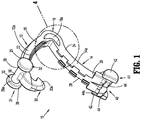
FIG. 1 is a side perspective view of an exemplary embodiment of the presently disclosed ligation clip in an open position; -
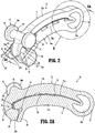
FIG. 2 is a side perspective view of the ligation clip shown inFIG.1 in the clamped position; -
FIG. 2A is a cross-sectional view taken alongsection line 2A-2A ofFIG. 2 ; -
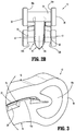
FIG. 2B is a front view of the ligation clip shown inFIG. 2 -
FIG. 3 is an enlarged view of the indicated area of detail shown inFIG. 2 ; -
FIG. 4 is an enlarged view of the indicated area of detail shown inFIG. 1 ; -
FIG. 4A is an enlarged view of the indicated area of detail shown inFIG. 4 ; -
FIG. 5 is a side view of the ligation clip shown inFIG. 1 in the open position placed about tissue; -
FIG. 6 is a side view of the ligation clip shown inFIG. 5 in the clamped position placed about tissue; -
FIG. 7 is an enlarged view of the indicated area of detail shown inFIG. 6 ; -
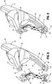
FIG. 8 is a perspective view from a distal end of the ligation clip shown inFIG. 1 and a clip applicator prior to engagement of the ligation clip to the jaws of the clip applicator; and -
FIG. 9 is a perspective view from the distal end of the ligation clip and clip applicator shown inFIG. 8 with the ligation clip engaged with the jaws of the clip applicator. - The presently disclosed ligation clip will now be described in detail with reference to the drawings in which like reference numerals designate identical or corresponding elements in each of the several views. It is to be understood that the disclosed embodiments are merely exemplary of the disclosure and may be embodied in various forms. Well-known functions or constructions are not described in detail to avoid obscuring the present disclosure in unnecessary detail. Specific structural and functional details disclosed herein are not to be interpreted as limiting, but merely as a basis for the claims and as a representative basis for teaching one skilled in the art to variously employ the present disclosure in virtually any appropriately detailed structure.
- In this description, the term "proximal" is used generally to refer to that portion of the device that is closer to a clinician, while the term "distal" is used generally to refer to that portion of the device that is farther from the clinician. In addition, the term "clinician" is used generally to refer to medical personnel including doctors, nurses, and support personnel.
- Referring to
FIGS. 1-3 , an exemplary embodiment of the presently disclosed ligation clip is shown generally asligation clip 10. Theligation clip 10 defines a longitudinal axis "Z" (FIG. 2A ) and includes afirst jaw 12, asecond jaw 14, and ahinge portion 16 coupling thefirst jaw 12 to the second jawl4. Thefirst jaw 12 is pivotable in relation to thesecond jaw 14 about thehinge portion 16 to move theligation clip 10 between an open position (FIG. 1 ) and a clamped position (FIG. 3 ). In embodiments, the first andsecond jaws FIG. 6 ) although other jaw configurations are envisioned. In embodiments, thehinge portion 16 may be integrally formed with the first andsecond jaws bore 16a to facilitate movement of thefirst jaw 12 in relation to thesecond jaw 14 between the open and clamped positions. The throughbore 16a also allows for substantially complete closure of the proximal portions of the first andsecond jaws - The
first jaw 12 has abody 12a having aproximal portion 18, adistal portion 20, and a clampingsurface 22. Thesecond jaw 14 has abody 14a having aproximal portion 24, adistal portion 26, and a clampingsurface 28. Theproximal portions second jaws hinge portion 16 such that theligation clip 10 is pivotable between an open position (FIG. 1 ) and a clamped position (FIG. 2 ). Thedistal portion 20 of thefirst jaw 12 includes afirst locking element 30 andengagement structure 31 including spacedbosses 32. Thefirst locking element 30 includes a hookedportion 30a that extends downwardly and proximally from thetissue clamping surface 22 to define a portion of a latching mechanism 34 (FIG. 2A ) that is configured to retain theligation clip 10 in a clamped position as described in further detail below. - The
engagement structure 31 of thefirst jaw 12 including thebosses 32 are supported on the distal portion of thebody 12a of thefirst jaw 12. Each of thebosses 32 includes atransverse portion 36 that extends outwardly of thebody 12a of thefirst jaw 12 and ahead portion 38 that is supported on thetransverse portion 38 outwardly of thebody 12a of thefirst jaw 12. Thehead portion 38 has a diameter or width, collectively referred to herein as "diameter", that is greater than the diameter of thetransverse portion 36 to define ashoulder 38a between thetransverse portion 36 and thehead portion 38. In embodiments, thetransverse portion 36 and/or thehead portion 38 of thebosses 32 is cylindrical although other configurations are envisioned. Thetransverse portion 36 of thebosses 32 may form part of a single member supported on the distal portion of thefirst jaw 12 that extends between thehead portions 38 of the spacedbosses 32. Thehead portions 38 of thebosses 32 are positioned outwardly from thebody 12a of thefirst jaw 12 such that thetransverse portion 36 are accessible tojaws FIG. 8 ) as described in further detail below to facilitate placement of theligation clip 10 on theclip applicator 100. - The
distal portion 26 of thesecond jaw 14 includes asecond locking element 40,engagement structure 41 including spacedbosses 42, and spacedteeth 44. The spacedteeth 44 are configured to engage and/or penetrate tissue. In embodiments, theteeth 44 have an apex or pointedend 44a that grips and stretches tissue as theligation clip 10 is moved from the open position (FIG. 1 ) towards the clamped position (FIG. 2 ) to improve the ligating characteristics of theligation clip 10. Thesecond locking element 40 defines an engagement surface 46 (FIG. 2A ) and acam surface 48. Thecam surface 48 and theengagement surface 46 are configured to receive and guide thefirst locking element 30 into locking engagement with thesecond locking element 40 when theligation clip 10 is moved to the clamped position (FIG. 3 ) to secure theligation clip 10 in the clamped position. In particular, thecam surface 48 is configured to deflect thefirst locking element 30 outwardly in a distal direction as thefirst locking element 30 passes over thecam surface 48 such that when thefirst locking element 30 moves past thecam surface 48, thefirst locking element 30 resiliently moves into engagement with the second locking element 40 (FIG. 2A ). - The
bosses 42 of the engagement structure 41(FIG. 2 ) of thesecond jaw 14 are similar to thebosses 32 of thefirst jaw 12. More specifically, thebosses 42 each include atransverse portion 50 and ahead portion 52. In embodiments, the head portion has aflat surface 52a that faces the spacedbosses 42. Thehead portion 52 has a diameter that is greater than the diameter of thetransverse portion 50 to define ashoulder 52b between thetransverse portion 50 and thehead portion 52. In embodiments, thetransverse portion 50 and/or thehead portion 52 of thebosses 42 is cylindrical although other configurations are envisioned, e.g., square, triangular, etc. Thetransverse portion 50 of each of thebosses 52 may form part of a single member supported on the distal portion of thesecond jaw 14 that extends between the spacedbosses 42. Thehead portions 50 of thebosses 42 are positioned outwardly from thebody 14a of thesecond jaw 14 such that thetransverse portions 50 of thebosses 42 are accessible to thejaws FIG. 8 ) to facilitate placement of theligation clip 10 on theclip applicator 100 as described in further detail below. - The
second jaw 14 includes aspring arm 56 that is positioned to engage thefirst locking element 30 when theligation element 10 is moved to the clamped position to retain thefirst locking element 30 and thesecond element 40 in the latched position (FIG. 2A ). Thespring arm 56 is positioned to engage and be deflected by thefirst locking element 30 to create a compressive force within thespring arm 56 that presses against the second locking element. - The
first clamping surface 22 is substantially flat and supports a longitudinal rib 60 (FIG. 4 ) including atissue engaging surface 62 that is in opposition with the clampingsurface 28 of thesecond jaw 14 when theligation clip 10 is in the clamped position (FIG. 3 ). In embodiments, thelongitudinal rib 60 is rectangular although other rib configurations are envisioned. In some embodiments, thetissue engaging surface 62 of thelongitudinal rib 60 is substantially flat and extends substantially the entire length of thetissue clamping surface 22. Alternately, it is envisioned that thelongitudinal rib 60 may include one or more longitudinal rib sections that are longitudinally spaced from each other and extend over a length less than the entire length of thetissue clamping surface 22, e.g., 50-80 percent of the length of thetissue clamping surface 22. - Referring also to
FIGS. 4 and 4A , thesecond clamping surface 28 is substantially flat and supports a first row ofprotrusions 70a and a second row ofprotrusions 70b. Each of theprotrusions 70a of the first row ofprotrusions 70a is spaced from but longitudinally aligned with each of theother protrusions 70a in the first row along a first side of thesecond clamping surface 28. Similarly, each of theprotrusions 70b of the second row ofprotrusions 70b is longitudinally aligned with each of theother protrusions 70b in the second row along a second side of thesecond clamping surface 28 opposite to the first side. Theprotrusions surface 28 to define an unobstructedcentral channel 71 between the first and second rows ofprotrusions second clamping surface 28. Thecentral channel 71 is receives thelongitudinal rib 60 when theligation clip 10 is in the clamped position. In embodiments, each of theprotrusions 70a on the first side of the clampingsurface 28 is longitudinally offset from each ofprotrusions 70b positioned on the other side of the clampingsurface 28 such that theprotrusions surface 28 along the length of the clampingsurface 28. - Each of the
protrusions FIG. 4A ) and aninner side wall 74. Thetissue engaging surface 72 is positioned in opposition to the clampingsurface 22 of thefirst jaw 12 when theligation clip 10 is in the clamped position. Theinner side wall 74 of each of theprotrusions longitudinal rib 60 when theligation clip 10 is in the clamped position (FIG. 2A ). - In embodiments, the
surgical ligation clip 10 may be made, in whole or in part, of a resilient bioabsorbable and/or biocompatible polymeric material. Examples of suitable bioabsorbable and/or biocompatible polymers include acetal polyoxymethylene (POM), polyethylene terephthalate (PET), polybutylene terephthalate (PBT), polyoxymethylene, polyetheretherketone (PEEK), polypropylene, and polyethylene or other thermoplastic materials having similar properties that can be injection-molded. The clip may also be made of a polymer material or materials in combination with radiolucent metal alloys. Alternately, other materials may be used to form theclip 10 including biocompatible metals, plastics and composites. - Referring to
FIGS. 5-7 , in use, theligation clip 10 is placed about tissue "T", e.g., a body vessel, such that the tissue "T" is positioned between thetissue clamping surface 22 of thefirst jaw 12 and thetissue clamping surface 28 of thesecond jaw 14. When theligation clip 10 is moved from the open position (FIG. 5 ) to the closed position (FIG. 6 ) in the direction indicated by arrow "A" inFIG. 5 , thefirst jaw 12 pivots in relation to thesecond jaw 14 about thehinge portion 16 to move the hookedportion 30a of thefirst locking element 30 into engagement with the portion of thesecond jaw 14 defining theengagement surface 46 to secure theligation clip 10 in the clamped position. In the clamped position, the tissue "T" is compressed between the first and second clamping surfaces 22, 28 of the first andsecond jaws longitudinal rib 60 of thefirst jaw 12 and theprotrusions second jaw 14. - The above described
ligation clip 10 including afirst jaw 12 having alongitudinal rib 60 and asecond jaw 14 including first and second rows ofprotrusions ligation clip 10 improve the retention forces of theligation clip 10 on the tissue "T" and minimize the likelihood that theligation clip 10 will slide in a direction parallel to the clamping surfaces 22, 28 of the first andsecond jaws ligation clip 10 has been clamped about the tissue "T". - Referring to
FIGS. 8 and 9 , thebosses second jaws ligation clip 10 on theclip applicator 100. In embodiments, theclip applicator 100 includesbody 112, afirst jaw 114, and asecond jaw 116. The first andsecond jaws body 112 and are movable between open and closed positions. Each of the first andsecond jaws clip applicator 100 includes acoupling structure 116 configured to engage thebosses second jaws ligation clip 10 to securely support theligation clip 10 on thejaws clip applicator 100. - Each of the
coupling structures 118 includes two spaced apart supportribs 120 that extend longitudinally along the first andsecond jaws clip applicator 100. Thesupport ribs 120 of thefirst jaw 114 define achannel 122 on thefirst jaw 114 that receives thefirst jaw 12 of theligation clip 10 and thesupport ribs 120 of thesecond jaw 114 define achannel 124 on thesecond jaw 114 that receives thesecond jaw 14 of theligation clip 10. Each of thesupport ribs 120 defines aconcavity 126 on a distal portion of therib 120. Theconcavities 126 defined in theribs 120 of thefirst jaw 114 are dimensioned and configured to receive thetransverse portions 36 of thebosses 32 of thefirst jaw 12 of theligation clip 10 and theconcavities 126 defined in theribs 120 of thesecond jaw 116 are dimensioned and configured to receive thetransverse portions 50 of thebosses 42 of thesecond jaw 14 of theligation clip 10. In embodiments, the diameter of theconcavities 126 corresponds to the diameter of thetransverse portions bosses head portions bosses concavities 126. - In use, the
transverse portions 36 of thebosses 32 of thefirst jaw 12 of theligation clip 10 are received within theconcavities 126 of thefirst jaw 114 of theclip applicator 100 and thetransverse portions 50 of thebosses 42 of thesecond jaw 14 of theligation clip 10 are received within theconcavities 126 of thesecond jaw 116. When theligation clip 10 is supported on theclip applicator 100, theoversized head portions bosses second jaws ligation clip 10 prevents theligation clip 10 from moving laterally and becoming dislodged from theclip applicator 100. This minimizes the likelihood of aligation clip 10 from becoming dislodged from aclip applicator 100 while maneuvering of theclip applicator 100 about tissue during placement of theligation clip 10 on tissue. - Persons skilled in the art will understand that the devices and methods specifically described herein and illustrated in the accompanying drawings are non-limiting exemplary embodiments. It is envisioned that the elements and features illustrated or described in connection with one exemplary embodiment may be combined with the elements and features of another without departing from the scope of the present disclosure. As well, one skilled in the art will appreciate further features and advantages of the disclosure based on the above-described embodiments. Accordingly, the disclosure is not to be limited by what has been particularly shown and described, except as indicated by the appended claims.
- The invention may be described by reference to the following numbered paragraphs:-
- 1. A ligation clip comprising:
- a first jaw including a body defining a first clamping surface, the first jaw supporting a first pair of spaced bosses; and
- a second jaw including a body defining a second clamping surface, the second jaw being pivotably coupled to the first jaw such that the ligation clip is movable between an open position and a clamped position, the second jaw supporting a second pair of spaced bosses;
- each of the bosses of the first and second pairs of bosses including a transverse portion and a head portion, the transverse portion extending outwardly of the body of the respective first or second jaw, and the head portion being supported on the transverse portion outwardly of the body of the respective first or second jaw, wherein the diameter of the head portion is greater than the diameter of the transverse portion to define a shoulder between the transverse portion and the head portion.
- 2. The ligation clip of paragraph 1, wherein the transverse portions of each of the bosses of the first and second pairs of spaced bosses is cylindrical.
- 3. The ligation clip of paragraph 1, wherein the transverse portions each of the bosses of the first pair of spaced bosses are formed by a single member that extends between the head portions.
- 4. The ligation clip of paragraph 1, wherein the first jaw includes a longitudinal rib having a tissue engaging surface that is positioned in opposition to the second clamping surface of the second jaw when the ligation clip is in the clamped position.
- 5. The ligation clip of paragraph 1, wherein the second jaw has a first row of protrusions supported on one side of the second clamping surface and a second row of protrusions supported on an opposite side of the second clamping surface, each of the protrusions of the first and second rows of protrusions having an inner side wall in opposition to the longitudinal rib when the ligation clip is in the clamped position.
- 6. The ligation clip of paragraph 5, wherein the first row of protrusions is laterally spaced from the second row of protrusions to define a channel that extends longitudinally between the first and second rows of protrusions, the channel being positioned to receive the stepped longitudinal rib when the ligation clip is in the clamped position.
- 7. The ligation clip of paragraph 6, wherein the protrusions in the first row of protrusions are longitudinally aligned and spaced from each other and the protrusions in the second row of protrusions are longitudinally aligned and spaced from each other.
- 8. The ligation clip of
paragraph 7, wherein each of the protrusions in the first row of protrusions are longitudinally offset from each of protrusions in the second row of protrusions such that the protrusions are alternatingly positioned on opposite sides of the second clamping surface along the length of the second clamping surface. - 9. The ligation clip of paragraph 1, wherein the first jaw includes a first locking element and the second jaw includes a second locking element, the first locking element being movable into engagement with the second locking element to retain the ligation clip in the clamped position.
- 10. The ligation clip of paragraph 9, wherein the first locking element includes a hooked portion that extends downwardly and proximally from the first tissue clamping surface and the second locking element defines an engagement surface for engaging the hooked portion.
- 11. The ligation clip of
paragraph 10, wherein the second locking element defines a cam surface that engages the hooked portion to bias the hooked portion outwardly of the second locking element such that the hooked portion resiliently returns to an unbiased state after passing over the second locking element to position the hooked portion in contact with the engagement surface. - 12. The ligation clip of paragraph 1, wherein the ligation clip is formed of a polymeric material.
- 13. The ligation clip of paragraph 1, wherein the second jaw includes a distal portion, the distal portion including spaced teeth that are configured to penetrate tissue.
- 14. The ligation clip of paragraph 1, wherein the teeth have an apex that grips and stretches tissue as the ligation clip is moved to the clamped position.
- 15. The ligation clip of paragraph 9, wherein the second jaw includes a spring arm that is positioned to engage and be deflected by the first locking element as the ligation clip is moved from the open position to the clamped position, the spring arm being positioned to urge the first and second locking elements to a latched position.
- 16. A ligation clip comprising:
- a first jaw including a body defining a first clamping surface, the first jaw supporting spaced bosses; and
- a second jaw including a body defining a second clamping surface, the second jaw being coupled to the first jaw and movable in relation to the first jaw between open and clamped positions;
- each of the spaced bosses including a transverse portion and a head portion, the transverse portion extending outwardly of the body of the first jaw, and the head portion being supported on the transverse portion outwardly of the body of the first jaw, wherein the diameter of the head portion is greater than the diameter of the transverse portion to define a shoulder between the transverse portion and the head portion.
- 17. The ligation clip of
paragraph 16, wherein the transverse portion of each of the spaced bosses is cylindrical. - 18. The ligation clip of paragraph 17, wherein the transverse portions of the spaced bosses are formed by a single member that extends between the heads of the spaced bosses.
- 19. A ligation clip comprising:
- a first jaw including a body defining a first clamping surface, the first jaw supporting spaced bosses; and
- a second jaw including a body defining a second clamping surface, the second jaw being coupled to the first jaw and movable in relation to the first jaw between open and clamped positions;
- each of the spaced bosses including a head portion spaced outwardly of the body of the first jaw, each of the head portions defining a shoulder that faces the body of the first jaw.
- 20. The ligation clip of paragraph 19, further including spaced bosses supported on the second jaw, each of the spaced bosses supported on the second jaw including a head portion spaced outwardly of the body of the second jaw, each of the head portions of the spaced bosses supported on the second jaw defining a shoulder that faces the body of the second jaw
Claims (15)
- A ligation clip comprising:a first jaw including a body defining a first clamping surface, the first jaw supporting a first pair of spaced bosses; anda second jaw including a body defining a second clamping surface, the second jaw being pivotably coupled to the first jaw such that the ligation clip is movable between an open position and a clamped position, the second jaw supporting a second pair of spaced bosses;each of the bosses of the first and second pairs of bosses including a transverse portion and a head portion, the transverse portion extending outwardly of the body of the respective first or second jaw, and the head portion being supported on the transverse portion outwardly of the body of the respective first or second jaw, wherein the diameter of the head portion is greater than the diameter of the transverse portion to define a shoulder between the transverse portion and the head portion.
- The ligation clip of claim 1, wherein the transverse portions of each of the bosses of the first and second pairs of spaced bosses is cylindrical.
- The ligation clip of claim 1 or claim 2, wherein the transverse portions each of the bosses of the first pair of spaced bosses are formed by a single member that extends between the head portions.
- The ligation clip of any preceding claim, wherein the first jaw includes a longitudinal rib having a tissue engaging surface that is positioned in opposition to the second clamping surface of the second jaw when the ligation clip is in the clamped position.
- The ligation clip of any preceding claim, wherein the second jaw has a first row of protrusions supported on one side of the second clamping surface and a second row of protrusions supported on an opposite side of the second clamping surface, each of the protrusions of the first and second rows of protrusions having an inner side wall in opposition to the longitudinal rib when the ligation clip is in the clamped position. ; preferably wherein the first row of protrusions is laterally spaced from the second row of protrusions to define a channel that extends longitudinally between the first and second rows of protrusions, the channel being positioned to receive the stepped longitudinal rib when the ligation clip is in the clamped position.
- The ligation clip of claim 5, wherein the protrusions in the first row of protrusions are longitudinally aligned and spaced from each other and the protrusions in the second row of protrusions are longitudinally aligned and spaced from each other; preferably wherein each of the protrusions in the first row of protrusions are longitudinally offset from each of protrusions in the second row of protrusions such that the protrusions are alternatingly positioned on opposite sides of the second clamping surface along the length of the second clamping surface.
- The ligation clip of any preceding claim, wherein the first jaw includes a first locking element and the second jaw includes a second locking element, the first locking element being movable into engagement with the second locking element to retain the ligation clip in the clamped position; preferably wherein the first locking element includes a hooked portion that extends downwardly and proximally from the first tissue clamping surface and the second locking element defines an engagement surface for engaging the hooked portion.
- The ligation clip of claim 7, wherein the second locking element defines a cam surface that engages the hooked portion to bias the hooked portion outwardly of the second locking element such that the hooked portion resiliently returns to an unbiased state after passing over the second locking element to position the hooked portion in contact with the engagement surface.
- The ligation clip of any preceding claim, wherein the ligation clip is formed of a polymeric material; and/or wherein the second jaw includes a distal portion, the distal portion including spaced teeth that are configured to penetrate tissue.
- The ligation clip of any preceding claim, wherein the teeth have an apex that grips and stretches tissue as the ligation clip is moved to the clamped position; preferably wherein the second jaw includes a spring arm that is positioned to engage and be deflected by the first locking element as the ligation clip is moved from the open position to the clamped position, the spring arm being positioned to urge the first and second locking elements to a latched position.
- A ligation clip comprising:a first jaw including a body defining a first clamping surface, the first jaw supporting spaced bosses; anda second jaw including a body defining a second clamping surface, the second jaw being coupled to the first jaw and movable in relation to the first jaw between open and clamped positions;each of the spaced bosses including a transverse portion and a head portion, the transverse portion extending outwardly of the body of the first jaw, and the head portion being supported on the transverse portion outwardly of the body of the first jaw, wherein the diameter of the head portion is greater than the diameter of the transverse portion to define a shoulder between the transverse portion and the head portion.
- The ligation clip of claim 11 wherein the transverse portion of each of the spaced bosses is cylindrical.
- The ligation clip of claim 12, wherein the transverse portions of the spaced bosses are formed by a single member that extends between the heads of the spaced bosses.
- A ligation clip comprising:a first jaw including a body defining a first clamping surface, the first jaw supporting spaced bosses; anda second jaw including a body defining a second clamping surface, the second jaw being coupled to the first jaw and movable in relation to the first jaw between open and clamped positions;each of the spaced bosses including a head portion spaced outwardly of the body of the first jaw, each of the head portions defining a shoulder that faces the body of the first jaw.
- The ligation clip of claim 14, further including spaced bosses supported on the second jaw, each of the spaced bosses supported on the second jaw including a head portion spaced outwardly of the body of the second jaw, each of the head portions of the spaced bosses supported on the second jaw defining a shoulder that faces the body of the second jaw
Applications Claiming Priority (2)
| Application Number | Priority Date | Filing Date | Title |
|---|---|---|---|
| US201862655854P | 2018-04-11 | 2018-04-11 | |
| US16/261,649 US10932789B2 (en) | 2018-04-11 | 2019-01-30 | Ligation clip with latching and retention features |
Publications (2)
| Publication Number | Publication Date |
|---|---|
| EP3552560A1 true EP3552560A1 (en) | 2019-10-16 |
| EP3552560B1 EP3552560B1 (en) | 2025-12-31 |
Family
ID=66105113
Family Applications (1)
| Application Number | Title | Priority Date | Filing Date |
|---|---|---|---|
| EP19168517.1A Active EP3552560B1 (en) | 2018-04-11 | 2019-04-10 | Ligature clamp with locking and holding features |
Country Status (5)
| Country | Link |
|---|---|
| US (1) | US10932789B2 (en) |
| EP (1) | EP3552560B1 (en) |
| JP (1) | JP2019181191A (en) |
| CN (1) | CN110353757B (en) |
| AU (1) | AU2019201340A1 (en) |
Cited By (3)
| Publication number | Priority date | Publication date | Assignee | Title |
|---|---|---|---|---|
| EP3610804A1 (en) * | 2018-08-13 | 2020-02-19 | Covidien LP | Ligation clip with improved hinge |
| CN112790814A (en) * | 2021-01-21 | 2021-05-14 | 吴一芃 | A kind of fast blood vessel blocking device for free skin flap transplantation operation and using method thereof |
| US12114866B2 (en) | 2020-03-26 | 2024-10-15 | Covidien Lp | Interoperative clip loading device |
Families Citing this family (14)
| Publication number | Priority date | Publication date | Assignee | Title |
|---|---|---|---|---|
| CA3032824C (en) | 2016-08-03 | 2021-04-27 | Teleflex Medical Incorporated | Surgical ligation clip |
| AU2018290343B2 (en) | 2017-06-22 | 2020-11-26 | Teleflex Medical Llc | Surgical clip |
| US20190133590A1 (en) * | 2017-11-03 | 2019-05-09 | Covidien Lp | Ligation clip with controlled tissue compression |
| WO2019099462A1 (en) | 2017-11-14 | 2019-05-23 | Teleflex Medical Incorporated | Surgical clip |
| USD907203S1 (en) * | 2019-08-02 | 2021-01-05 | Covidien Lp | Ligation clip |
| USD907204S1 (en) * | 2019-08-02 | 2021-01-05 | Covidien Lp | Ligation clip |
| USD907200S1 (en) * | 2019-08-05 | 2021-01-05 | Covidien Lp | Ligation clip |
| CN114929119A (en) * | 2019-12-19 | 2022-08-19 | 泰利福医疗公司 | Surgical clamp |
| WO2021230105A1 (en) * | 2020-05-11 | 2021-11-18 | テルモ株式会社 | Clamp |
| EP4178465A4 (en) * | 2020-07-08 | 2024-04-03 | A2 Medical Systems LLC | Ligation clips with anti-migration features |
| CN112155636A (en) * | 2020-10-13 | 2021-01-01 | 常州安康医疗器械有限公司 | Full-degradable metal-based vascular tissue closing clamp for endoscope |
| CN113040856B (en) * | 2021-04-27 | 2022-08-09 | 浙江微度医疗器械有限公司 | Reinforced ligation clip |
| KR102923701B1 (en) * | 2021-08-19 | 2026-02-05 | 보스턴 사이언티픽 메디칼 디바이스 리미티드 | Endoscope clip with positive locking mechanism |
| CN115444490B (en) * | 2022-09-16 | 2026-02-17 | 山东威瑞外科医用制品有限公司 | Clamp for removing clamp jaw |
Citations (3)
| Publication number | Priority date | Publication date | Assignee | Title |
|---|---|---|---|---|
| US4834096A (en) * | 1987-10-26 | 1989-05-30 | Edward Weck Incorporated | Plastic ligating clips |
| EP2074954A1 (en) * | 2007-12-31 | 2009-07-01 | Teleflex Medical Incorporated | Ligation clip with flexible clamping feature |
| US20120083803A1 (en) * | 2010-10-02 | 2012-04-05 | Patel Manoj B | Asymmetrical surgical clip with penetrating lock, non-slip clamping surface, severable hinge, hinge boss and pivoting applicator tip |
Family Cites Families (111)
| Publication number | Priority date | Publication date | Assignee | Title |
|---|---|---|---|---|
| GB253710A (en) | 1925-06-04 | 1926-06-24 | William Reid | Improvements in steam engines |
| US3439523A (en) | 1964-03-30 | 1969-04-22 | Peter B Samuels | Hemostatic clip constructions |
| BE654195A (en) | 1964-10-09 | 1965-02-01 | ||
| US3713533A (en) | 1971-04-28 | 1973-01-30 | Codman & Shurtleff | Hemostatic clip holder |
| US4076120A (en) | 1976-12-10 | 1978-02-28 | American Hospital Supply Corporation | Cartridge for holding hemostatic clips |
| US4187712A (en) | 1977-04-08 | 1980-02-12 | Samuels Peter B | Hemostatic clip applicator |
| US4146130A (en) | 1977-04-08 | 1979-03-27 | Samuels Peter B | Hemostatic clip, clip applicator and cartridge therefor |
| US4212390A (en) | 1977-10-20 | 1980-07-15 | Propper Manufacturing Co., Inc. | Wound clip rack |
| US4212303A (en) | 1978-07-17 | 1980-07-15 | Hollister Incorporated | Umbilical cord clamp |
| US4390019A (en) | 1979-02-28 | 1983-06-28 | Leveen Harry H | Blood vessel clamp |
| US4418694A (en) | 1979-06-18 | 1983-12-06 | Ethicon, Inc. | Non-metallic, bio-compatible hemostatic clips |
| US4294355A (en) | 1979-12-06 | 1981-10-13 | Ethicon, Inc. | Cartridge for hemostatic clips |
| US4344531A (en) | 1980-09-08 | 1982-08-17 | Edward Weck & Company, Inc. | Hemostatic clip cartridge |
| US4346869A (en) | 1981-03-12 | 1982-08-31 | Macneill Robert L | Tube clamp |
| US4412617A (en) | 1981-07-20 | 1983-11-01 | Ethicon, Inc. | Ligating clip package |
| US4361229A (en) | 1981-08-03 | 1982-11-30 | Ethicon, Inc. | Cartridge for hemostatic clips |
| US4449531A (en) | 1981-08-27 | 1984-05-22 | Ethicon, Inc. | Non-metallic, bio-compatible hemostatic clips with interlocking latch means |
| US4550729A (en) | 1981-08-27 | 1985-11-05 | Ethicon, Inc. | Non-metallic, bio-compatible hemostatic clips with interlocking latch means |
| US4485953A (en) | 1982-04-05 | 1984-12-04 | Senco Products, Inc. | Surgical stapling instrument and cartridge therefor |
| US4487205A (en) | 1982-04-26 | 1984-12-11 | Ethicon, Inc. | Non-metallic, bio-compatible hemostatic clips |
| US4696396A (en) | 1985-12-19 | 1987-09-29 | Samuels Peter B | Hemostatic clip cartridge |
| US4726372A (en) | 1986-09-19 | 1988-02-23 | Metatech Corporation | Hemostatic clip |
| US4971198A (en) | 1988-04-18 | 1990-11-20 | Edward Weck Incorporated | Hemostatic clip and cartridge assembly |
| US5062846A (en) | 1989-03-28 | 1991-11-05 | Edward Weck Incorporated | Penetrating plastic ligating clip |
| US4972949A (en) | 1989-09-26 | 1990-11-27 | Horizon Surgical, Inc. | Hemostatic clip holder for small clips |
| US4936447A (en) | 1989-09-26 | 1990-06-26 | Horizon Surgical Inc. | Hemostatic clip holder |
| US5100416A (en) | 1989-10-17 | 1992-03-31 | Edward Weck Incorporated | Ligating clip applying instrument |
| US4961499A (en) | 1990-01-04 | 1990-10-09 | Pilling Co. | Hemostatic clip cartridge |
| US5046624A (en) | 1990-08-13 | 1991-09-10 | Murphy Susan A | Surgical instrument stand |
| US5050272A (en) | 1990-10-16 | 1991-09-24 | Anago, Inc. | Closure member for an ice bag |
| US5201416A (en) | 1990-10-22 | 1993-04-13 | Edward Weck Incorporated | Hemostatic clip cartridge |
| US5046611A (en) | 1990-10-22 | 1991-09-10 | Edward Weck Incorporated | Hemostatic clip cartridge |
| US5423831A (en) | 1991-01-24 | 1995-06-13 | Nates; Colin | Clamp |
| US5279416A (en) | 1992-06-05 | 1994-01-18 | Edward Weck Incorporated | Ligating device cartridge with separable retainer |
| US5403327A (en) | 1992-12-31 | 1995-04-04 | Pilling Weck Incorporated | Surgical clip applier |
| US5697942A (en) | 1994-07-31 | 1997-12-16 | Palti; Yoram | Internal vascular clamp |
| US5908430A (en) | 1995-06-07 | 1999-06-01 | Appleby; Timothy | Easy loading hemostatic clip and cartridge |
| US5564262A (en) | 1995-07-20 | 1996-10-15 | Ethicon, Inc. | Ligaclip loading machine and process |
| US5713912A (en) | 1995-08-30 | 1998-02-03 | Stress Management, Inc. | Ligating clip having ramp-shaped vessel clamping members and tool for applying same |
| US5676676A (en) | 1995-08-30 | 1997-10-14 | Porter; Wayne | Ligating clip having ramp-shaped vessel-clamping members |
| FR2751863B1 (en) | 1996-08-01 | 1999-01-22 | Vitalitec International | HEMOSTATIC CLIPS SUPPORT |
| GB9707204D0 (en) | 1997-04-09 | 1997-05-28 | Price Invena Aps | Clamping and cutting devices |
| US6044971A (en) | 1997-10-10 | 2000-04-04 | United States Surgical Corporation | Clip cartridge |
| US5921991A (en) | 1997-10-23 | 1999-07-13 | Biomax Technologies Inc. | Multi-colored umbilical cord clamp |
| US6228097B1 (en) | 1999-01-22 | 2001-05-08 | Scion International, Inc. | Surgical instrument for clipping and cutting blood vessels and organic structures |
| US6217590B1 (en) | 1999-01-22 | 2001-04-17 | Scion International, Inc. | Surgical instrument for applying multiple staples and cutting blood vessels and organic structures and method therefor |
| DE19903752C1 (en) | 1999-01-30 | 2000-03-30 | Aesculap Ag & Co Kg | Clip magazine for haemostatic medical clip driver has independent actuated clamps for arms and bases of clips |
| IL132913A (en) | 1999-11-14 | 2004-09-27 | Porat Michael | Device and method for clamping and cutting a flexible deformable tube |
| US6419682B1 (en) | 2000-03-24 | 2002-07-16 | Timothy Appleby | Hemostatic clip cartridge |
| US6391035B1 (en) | 2000-03-24 | 2002-05-21 | Timothy Appleby | Hemostatic clip removal instrument |
| US6273253B1 (en) | 2000-07-07 | 2001-08-14 | Vitalitec International, Inc. | Cartridge and system for holding and applying clips |
| US20020046961A1 (en) | 2000-10-19 | 2002-04-25 | Scion International | Surgical clip holder and method therefor |
| DE10116168A1 (en) | 2001-03-31 | 2001-11-29 | Joachim Heinzl | Clip has gripper arms operated by articulated lever mechanism and joined by spacer piece, tie rod, pulley cable, locking mechanism with cogging and pawl |
| US20020177863A1 (en) | 2001-05-24 | 2002-11-28 | Mandel Stanley R. | Surface treated ligating clip |
| US6824547B2 (en) | 2001-07-13 | 2004-11-30 | Pilling Weck Incorporated | Endoscopic clip applier and method |
| US20040199178A1 (en) | 2001-10-09 | 2004-10-07 | Small George H. | Umbilical cord clamp and methods of using same |
| US20030069589A1 (en) | 2001-10-09 | 2003-04-10 | Small George H. | Umbilical cord clamp and methods of using same |
| US7211091B2 (en) | 2002-08-27 | 2007-05-01 | Pilling Weck Incorporated | Fingertip-actuated surgical clip applier and related methods |
| US6880699B2 (en) | 2002-08-27 | 2005-04-19 | Pilling Weck Incorporated | Cartridge for holding asymmetric surgical clips |
| US7131977B2 (en) | 2002-08-27 | 2006-11-07 | Pilling Weck Incorporated | Apparatus and method for removing a clip |
| US6863675B2 (en) | 2002-09-20 | 2005-03-08 | Pilling Weck Incorporated | Ligating clip with integral penetrating hook |
| US7052504B2 (en) | 2002-11-19 | 2006-05-30 | Teleflex Incorporated | Automated-feed surgical clip applier and related methods |
| US7211092B2 (en) | 2002-11-19 | 2007-05-01 | Pilling Weck Incorporated | Automated-feed surgical clip applier and related methods |
| WO2004080290A2 (en) | 2003-03-11 | 2004-09-23 | Tyco Healthcare Group, Lp | Clip applying apparatus with angled jaw |
| US7144402B2 (en) | 2003-06-16 | 2006-12-05 | Synovis Life Technologies, Inc. | Vascular clamp |
| US7326223B2 (en) | 2004-01-22 | 2008-02-05 | Teleflex Medical Incorporated | Ligating clip with integral cutting guide |
| US7316696B2 (en) | 2004-01-22 | 2008-01-08 | Teleflex Medical Incorporated | Ligating clip with integral interlocking latch mechanism |
| US20050165423A1 (en) | 2004-01-23 | 2005-07-28 | Pilling Weck Incorporated | Ligating clip with integral tissue-securing mechanism |
| US7001412B2 (en) | 2004-01-28 | 2006-02-21 | Pilling Weck Incorporated | Surgical clip with integral suture-securing mechanism |
| US7585304B2 (en) | 2004-02-02 | 2009-09-08 | Teleflex Medical Incorporated | Endoscopic clip applying apparatus with improved aperture for clip release and related method |
| US7857129B2 (en) | 2004-03-07 | 2010-12-28 | Synthes Usa, Llc | Container and carrier system for surgical auxiliary material |
| US7452368B2 (en) | 2004-09-15 | 2008-11-18 | Ethicon, Inc. | System for holding surgical fasteners |
| US20060124485A1 (en) | 2004-12-10 | 2006-06-15 | Kennedy Daniel L | Enhanced visibility cartridge with improved retainer |
| US20060217749A1 (en) | 2005-03-24 | 2006-09-28 | Pilling Weck Incorporated | Reduced closure force ligating clip |
| DE102005045006B3 (en) | 2005-09-21 | 2007-01-04 | Cardiomedical Gmbh | Case for haemostatic clamps for surgical use has bottom part containing pockets and bracket to hold clamp and top part with clamp parts to hold clamp securely in each clamp pocket |
| US20070083218A1 (en) | 2005-10-12 | 2007-04-12 | A Morris Steven | Coated ligating clip |
| US20070118161A1 (en) | 2005-11-22 | 2007-05-24 | Kennedy Daniel L | Non-snag polymer ligating clip |
| US9486225B2 (en) | 2005-12-22 | 2016-11-08 | Robert E. Michler | Exclusion of the left atrial appendage |
| US9480480B2 (en) | 2005-12-22 | 2016-11-01 | Albert N. Santilli | Vascular and intestinal occlusion |
| US8328458B2 (en) | 2007-07-20 | 2012-12-11 | Twin Bay Medical, Inc. | Sanitary clamp |
| US8042687B2 (en) | 2007-12-14 | 2011-10-25 | Vesocclude Medical Llc | Hemostatic clip cartridge |
| DE102008018158A1 (en) | 2008-04-10 | 2009-10-15 | Aesculap Ag | Ligature clip magazine and bearing body for use in this |
| DE102009035756A1 (en) | 2009-07-24 | 2011-01-27 | Aesculap Ag | Clip carrier device |
| US8425515B2 (en) | 2009-10-30 | 2013-04-23 | Depuy Spine, Inc. | Bone graft loading instruments and methods of connecting a bone graft to a bone plate |
| US20110224700A1 (en) | 2010-03-09 | 2011-09-15 | Teleflex Medical Incorporated | Narrow Profile Surgical Ligation Clip |
| WO2013040306A1 (en) * | 2010-03-09 | 2013-03-21 | Teleflex Medical Incorporated | Narrow profile surgical ligation clip |
| US10136898B2 (en) | 2010-03-09 | 2018-11-27 | Teleflex Medical Incorporated | Narrow profile surgical ligation clip |
| US20110295291A1 (en) | 2010-05-28 | 2011-12-01 | Dean Trivisani | Novel Vascular Clamp |
| WO2012122006A2 (en) | 2011-03-04 | 2012-09-13 | Jenkins Clinic, Inc. | Surgical ligation clip and applicator device |
| CA2830073A1 (en) * | 2011-03-21 | 2012-09-27 | The Administrators Of The Tulane Educational Fund | Multi-component detachable jaw tools and methods of using and making same |
| US9517178B2 (en) | 2011-04-26 | 2016-12-13 | Vitalitec International, Inc. | Cartridge for surgical fasteners with integrated lock system |
| JP2014531248A (en) | 2011-09-15 | 2014-11-27 | テレフレックス メディカル インコーポレイテッドTeleflex Medical Incorporated | Automatic surgical ligation clip applier |
| WO2013040467A2 (en) | 2011-09-15 | 2013-03-21 | Teleflex Medical Incorporated | Manual surgical ligation clip applier |
| WO2013059826A1 (en) * | 2011-10-20 | 2013-04-25 | Atsina Surgical, Llc | Ligation clip |
| DE102011056821A1 (en) | 2011-12-21 | 2013-06-27 | Aesculap Ag | Medical clip carrier device |
| US9282972B1 (en) | 2012-10-14 | 2016-03-15 | Innovative Urololy, Llc | Surgical clips with penetrating locking mechanism and non-slip clamping surfaces |
| US10226273B2 (en) | 2013-03-14 | 2019-03-12 | Ethicon Llc | Mechanical fasteners for use with surgical energy devices |
| WO2016081822A1 (en) | 2014-11-21 | 2016-05-26 | Novate Medical Technologies, Llc | Multi-component detachable cutting and clamping tool and methods of using same |
| CN106264647A (en) | 2015-06-04 | 2017-01-04 | 上海林超医疗设备科技有限公司 | There is out the Clip Applier of folder function |
| EP3310270A4 (en) | 2015-06-16 | 2019-04-10 | Nanova Biomaterials, Inc. | SURGICAL LIGATURE FORCEPS ANTI-MIGRATION |
| CN204839635U (en) | 2015-06-19 | 2015-12-09 | 江西圣济药业有限公司 | Make bit -type umbilical cord clamps by oneself |
| WO2017019865A1 (en) | 2015-07-30 | 2017-02-02 | Teleflex Medical Incorporated | Snap-on surgical clip cartridge |
| CN105078536A (en) | 2015-08-26 | 2015-11-25 | 施青青 | Duplex tissue clip and clip applier |
| CA3032824C (en) | 2016-08-03 | 2021-04-27 | Teleflex Medical Incorporated | Surgical ligation clip |
| CN206934138U (en) * | 2016-12-30 | 2018-01-30 | 四川国纳科技有限公司 | A kind of ligation clip |
| EP3600083B1 (en) | 2017-03-21 | 2024-08-28 | Teleflex Medical Incorporated | Flexible stabilizing member for a clip applier |
| WO2018175605A1 (en) | 2017-03-21 | 2018-09-27 | Teleflex Medical Incorporated | Clip applier with replaceable tips |
| US11266408B2 (en) | 2017-03-21 | 2022-03-08 | Teleflex Medical Incorporated | Clip applier having stabilizing member |
| CN110740695B (en) | 2017-03-21 | 2024-10-25 | 泰利福医疗公司 | Surgical Clips and Clip Appliers |
| USD808522S1 (en) | 2017-07-11 | 2018-01-23 | Vesolock Medical, Llc | Latching ends of a polymer ligating clip |
| US11317923B2 (en) * | 2018-08-13 | 2022-05-03 | Covidien Lp | Ligation clip with improved hinge |
-
2019
- 2019-01-30 US US16/261,649 patent/US10932789B2/en active Active
- 2019-02-26 AU AU2019201340A patent/AU2019201340A1/en not_active Abandoned
- 2019-03-28 CN CN201910243331.0A patent/CN110353757B/en active Active
- 2019-03-29 JP JP2019067146A patent/JP2019181191A/en active Pending
- 2019-04-10 EP EP19168517.1A patent/EP3552560B1/en active Active
Patent Citations (3)
| Publication number | Priority date | Publication date | Assignee | Title |
|---|---|---|---|---|
| US4834096A (en) * | 1987-10-26 | 1989-05-30 | Edward Weck Incorporated | Plastic ligating clips |
| EP2074954A1 (en) * | 2007-12-31 | 2009-07-01 | Teleflex Medical Incorporated | Ligation clip with flexible clamping feature |
| US20120083803A1 (en) * | 2010-10-02 | 2012-04-05 | Patel Manoj B | Asymmetrical surgical clip with penetrating lock, non-slip clamping surface, severable hinge, hinge boss and pivoting applicator tip |
Cited By (5)
| Publication number | Priority date | Publication date | Assignee | Title |
|---|---|---|---|---|
| EP3610804A1 (en) * | 2018-08-13 | 2020-02-19 | Covidien LP | Ligation clip with improved hinge |
| US11317923B2 (en) | 2018-08-13 | 2022-05-03 | Covidien Lp | Ligation clip with improved hinge |
| US12114866B2 (en) | 2020-03-26 | 2024-10-15 | Covidien Lp | Interoperative clip loading device |
| CN112790814A (en) * | 2021-01-21 | 2021-05-14 | 吴一芃 | A kind of fast blood vessel blocking device for free skin flap transplantation operation and using method thereof |
| CN112790814B (en) * | 2021-01-21 | 2023-08-01 | 吴一芃 | A rapid vascular occlusion device for free skin flap transplantation |
Also Published As
| Publication number | Publication date |
|---|---|
| AU2019201340A1 (en) | 2019-10-31 |
| CN110353757A (en) | 2019-10-22 |
| JP2019181191A (en) | 2019-10-24 |
| US20190314031A1 (en) | 2019-10-17 |
| EP3552560B1 (en) | 2025-12-31 |
| CN110353757B (en) | 2024-01-30 |
| US10932789B2 (en) | 2021-03-02 |
Similar Documents
| Publication | Publication Date | Title |
|---|---|---|
| EP3552560B1 (en) | Ligature clamp with locking and holding features | |
| EP3610804B1 (en) | Ligation clip with improved hinge | |
| US11304704B2 (en) | Surgical clip applier and ligation clips | |
| US11033279B2 (en) | Ligation clip with retention features | |
| EP3517056B1 (en) | Ligation clip with tissue rentention features | |
| US20190133590A1 (en) | Ligation clip with controlled tissue compression | |
| EP3552561B1 (en) | Ligation clip with latching and retention features | |
| US20180271534A1 (en) | Clip applier with stabilizing member | |
| WO2018175605A1 (en) | Clip applier with replaceable tips | |
| US20200405315A1 (en) | Ligation clip with retention features | |
| US20240350147A1 (en) | Clip applier | |
| US12318094B2 (en) | Clip applier | |
| EP3771439A1 (en) | Ligation clip with improved latch mechanism | |
| US20210137524A1 (en) | Multi-Part Ligation Clip |
Legal Events
| Date | Code | Title | Description |
|---|---|---|---|
| PUAI | Public reference made under article 153(3) epc to a published international application that has entered the european phase |
Free format text: ORIGINAL CODE: 0009012 |
|
| STAA | Information on the status of an ep patent application or granted ep patent |
Free format text: STATUS: THE APPLICATION HAS BEEN PUBLISHED |
|
| AK | Designated contracting states |
Kind code of ref document: A1 Designated state(s): AL AT BE BG CH CY CZ DE DK EE ES FI FR GB GR HR HU IE IS IT LI LT LU LV MC MK MT NL NO PL PT RO RS SE SI SK SM TR |
|
| AX | Request for extension of the european patent |
Extension state: BA ME |
|
| STAA | Information on the status of an ep patent application or granted ep patent |
Free format text: STATUS: REQUEST FOR EXAMINATION WAS MADE |
|
| 17P | Request for examination filed |
Effective date: 20200403 |
|
| RBV | Designated contracting states (corrected) |
Designated state(s): AL AT BE BG CH CY CZ DE DK EE ES FI FR GB GR HR HU IE IS IT LI LT LU LV MC MK MT NL NO PL PT RO RS SE SI SK SM TR |
|
| STAA | Information on the status of an ep patent application or granted ep patent |
Free format text: STATUS: EXAMINATION IS IN PROGRESS |
|
| 17Q | First examination report despatched |
Effective date: 20210707 |
|
| GRAP | Despatch of communication of intention to grant a patent |
Free format text: ORIGINAL CODE: EPIDOSNIGR1 |
|
| STAA | Information on the status of an ep patent application or granted ep patent |
Free format text: STATUS: GRANT OF PATENT IS INTENDED |
|
| INTG | Intention to grant announced |
Effective date: 20251008 |
|
| GRAS | Grant fee paid |
Free format text: ORIGINAL CODE: EPIDOSNIGR3 |
|
| GRAA | (expected) grant |
Free format text: ORIGINAL CODE: 0009210 |
|
| STAA | Information on the status of an ep patent application or granted ep patent |
Free format text: STATUS: THE PATENT HAS BEEN GRANTED |
|
| AK | Designated contracting states |
Kind code of ref document: B1 Designated state(s): AL AT BE BG CH CY CZ DE DK EE ES FI FR GB GR HR HU IE IS IT LI LT LU LV MC MK MT NL NO PL PT RO RS SE SI SK SM TR |
|
| REG | Reference to a national code |
Ref country code: CH Ref legal event code: F10 Free format text: ST27 STATUS EVENT CODE: U-0-0-F10-F00 (AS PROVIDED BY THE NATIONAL OFFICE) Effective date: 20251231 Ref country code: GB Ref legal event code: FG4D |
|
| REG | Reference to a national code |
Ref country code: DE Ref legal event code: R096 Ref document number: 602019079741 Country of ref document: DE |
|
| REG | Reference to a national code |
Ref country code: IE Ref legal event code: FG4D |
|
| PGFP | Annual fee paid to national office [announced via postgrant information from national office to epo] |
Ref country code: GB Payment date: 20260319 Year of fee payment: 8 |
|
| REG | Reference to a national code |
Ref country code: LT Ref legal event code: MG9D |
|
| PG25 | Lapsed in a contracting state [announced via postgrant information from national office to epo] |
Ref country code: NO Free format text: LAPSE BECAUSE OF FAILURE TO SUBMIT A TRANSLATION OF THE DESCRIPTION OR TO PAY THE FEE WITHIN THE PRESCRIBED TIME-LIMIT Effective date: 20260331 |
|
| PG25 | Lapsed in a contracting state [announced via postgrant information from national office to epo] |
Ref country code: FI Free format text: LAPSE BECAUSE OF FAILURE TO SUBMIT A TRANSLATION OF THE DESCRIPTION OR TO PAY THE FEE WITHIN THE PRESCRIBED TIME-LIMIT Effective date: 20251231 Ref country code: HR Free format text: LAPSE BECAUSE OF FAILURE TO SUBMIT A TRANSLATION OF THE DESCRIPTION OR TO PAY THE FEE WITHIN THE PRESCRIBED TIME-LIMIT Effective date: 20251231 |
|
| PG25 | Lapsed in a contracting state [announced via postgrant information from national office to epo] |
Ref country code: RS Free format text: LAPSE BECAUSE OF FAILURE TO SUBMIT A TRANSLATION OF THE DESCRIPTION OR TO PAY THE FEE WITHIN THE PRESCRIBED TIME-LIMIT Effective date: 20260331 |
|
| PG25 | Lapsed in a contracting state [announced via postgrant information from national office to epo] |
Ref country code: LV Free format text: LAPSE BECAUSE OF FAILURE TO SUBMIT A TRANSLATION OF THE DESCRIPTION OR TO PAY THE FEE WITHIN THE PRESCRIBED TIME-LIMIT Effective date: 20251231 |
|
| PG25 | Lapsed in a contracting state [announced via postgrant information from national office to epo] |
Ref country code: BG Free format text: LAPSE BECAUSE OF FAILURE TO SUBMIT A TRANSLATION OF THE DESCRIPTION OR TO PAY THE FEE WITHIN THE PRESCRIBED TIME-LIMIT Effective date: 20251231 |
|
| REG | Reference to a national code |
Ref country code: NL Ref legal event code: MP Effective date: 20251231 |
|
| REG | Reference to a national code |
Ref country code: AT Ref legal event code: MK05 Ref document number: 1872324 Country of ref document: AT Kind code of ref document: T Effective date: 20251231 |
|
| PG25 | Lapsed in a contracting state [announced via postgrant information from national office to epo] |
Ref country code: NL Free format text: LAPSE BECAUSE OF FAILURE TO SUBMIT A TRANSLATION OF THE DESCRIPTION OR TO PAY THE FEE WITHIN THE PRESCRIBED TIME-LIMIT Effective date: 20251231 |
|
| PG25 | Lapsed in a contracting state [announced via postgrant information from national office to epo] |
Ref country code: LT Free format text: LAPSE BECAUSE OF FAILURE TO SUBMIT A TRANSLATION OF THE DESCRIPTION OR TO PAY THE FEE WITHIN THE PRESCRIBED TIME-LIMIT Effective date: 20251231 |
|
| PG25 | Lapsed in a contracting state [announced via postgrant information from national office to epo] |
Ref country code: SM Free format text: LAPSE BECAUSE OF FAILURE TO SUBMIT A TRANSLATION OF THE DESCRIPTION OR TO PAY THE FEE WITHIN THE PRESCRIBED TIME-LIMIT Effective date: 20251231 |
|
| PG25 | Lapsed in a contracting state [announced via postgrant information from national office to epo] |
Ref country code: ES Free format text: LAPSE BECAUSE OF FAILURE TO SUBMIT A TRANSLATION OF THE DESCRIPTION OR TO PAY THE FEE WITHIN THE PRESCRIBED TIME-LIMIT Effective date: 20251231 |
|
| PG25 | Lapsed in a contracting state [announced via postgrant information from national office to epo] |
Ref country code: PL Free format text: LAPSE BECAUSE OF FAILURE TO SUBMIT A TRANSLATION OF THE DESCRIPTION OR TO PAY THE FEE WITHIN THE PRESCRIBED TIME-LIMIT Effective date: 20251231 |
|
| PG25 | Lapsed in a contracting state [announced via postgrant information from national office to epo] |
Ref country code: IT Free format text: LAPSE BECAUSE OF FAILURE TO SUBMIT A TRANSLATION OF THE DESCRIPTION OR TO PAY THE FEE WITHIN THE PRESCRIBED TIME-LIMIT Effective date: 20251231 |
|
| PGFP | Annual fee paid to national office [announced via postgrant information from national office to epo] |
Ref country code: DE Payment date: 20260319 Year of fee payment: 8 |
|
| PG25 | Lapsed in a contracting state [announced via postgrant information from national office to epo] |
Ref country code: AT Free format text: LAPSE BECAUSE OF FAILURE TO SUBMIT A TRANSLATION OF THE DESCRIPTION OR TO PAY THE FEE WITHIN THE PRESCRIBED TIME-LIMIT Effective date: 20251231 |
|
| PG25 | Lapsed in a contracting state [announced via postgrant information from national office to epo] |
Ref country code: EE Free format text: LAPSE BECAUSE OF FAILURE TO SUBMIT A TRANSLATION OF THE DESCRIPTION OR TO PAY THE FEE WITHIN THE PRESCRIBED TIME-LIMIT Effective date: 20251231 |
|
| PG25 | Lapsed in a contracting state [announced via postgrant information from national office to epo] |
Ref country code: IS Free format text: LAPSE BECAUSE OF FAILURE TO SUBMIT A TRANSLATION OF THE DESCRIPTION OR TO PAY THE FEE WITHIN THE PRESCRIBED TIME-LIMIT Effective date: 20260430 Ref country code: PT Free format text: LAPSE BECAUSE OF FAILURE TO SUBMIT A TRANSLATION OF THE DESCRIPTION OR TO PAY THE FEE WITHIN THE PRESCRIBED TIME-LIMIT Effective date: 20260430 |
|
| PG25 | Lapsed in a contracting state [announced via postgrant information from national office to epo] |
Ref country code: CZ Free format text: LAPSE BECAUSE OF FAILURE TO SUBMIT A TRANSLATION OF THE DESCRIPTION OR TO PAY THE FEE WITHIN THE PRESCRIBED TIME-LIMIT Effective date: 20251231 |
|
| PG25 | Lapsed in a contracting state [announced via postgrant information from national office to epo] |
Ref country code: SK Free format text: LAPSE BECAUSE OF FAILURE TO SUBMIT A TRANSLATION OF THE DESCRIPTION OR TO PAY THE FEE WITHIN THE PRESCRIBED TIME-LIMIT Effective date: 20251231 |
|
| PG25 | Lapsed in a contracting state [announced via postgrant information from national office to epo] |
Ref country code: SE Free format text: LAPSE BECAUSE OF FAILURE TO SUBMIT A TRANSLATION OF THE DESCRIPTION OR TO PAY THE FEE WITHIN THE PRESCRIBED TIME-LIMIT Effective date: 20251231 |