EP3552550B1 - Machine-learning based contrast agent administration - Google Patents
Machine-learning based contrast agent administration Download PDFInfo
- Publication number
- EP3552550B1 EP3552550B1 EP19167260.9A EP19167260A EP3552550B1 EP 3552550 B1 EP3552550 B1 EP 3552550B1 EP 19167260 A EP19167260 A EP 19167260A EP 3552550 B1 EP3552550 B1 EP 3552550B1
- Authority
- EP
- European Patent Office
- Prior art keywords
- patient
- contrast agent
- data
- contrast
- scan
- Prior art date
- Legal status (The legal status is an assumption and is not a legal conclusion. Google has not performed a legal analysis and makes no representation as to the accuracy of the status listed.)
- Active
Links
Images


Classifications
-
- A—HUMAN NECESSITIES
- A61—MEDICAL OR VETERINARY SCIENCE; HYGIENE
- A61B—DIAGNOSIS; SURGERY; IDENTIFICATION
- A61B6/00—Apparatus or devices for radiation diagnosis; Apparatus or devices for radiation diagnosis combined with radiation therapy equipment
- A61B6/50—Apparatus or devices for radiation diagnosis; Apparatus or devices for radiation diagnosis combined with radiation therapy equipment specially adapted for specific body parts; specially adapted for specific clinical applications
- A61B6/504—Apparatus or devices for radiation diagnosis; Apparatus or devices for radiation diagnosis combined with radiation therapy equipment specially adapted for specific body parts; specially adapted for specific clinical applications for diagnosis of blood vessels, e.g. by angiography
-
- A—HUMAN NECESSITIES
- A61—MEDICAL OR VETERINARY SCIENCE; HYGIENE
- A61B—DIAGNOSIS; SURGERY; IDENTIFICATION
- A61B5/00—Measuring for diagnostic purposes; Identification of persons
- A61B5/72—Signal processing specially adapted for physiological signals or for diagnostic purposes
- A61B5/7235—Details of waveform analysis
- A61B5/7264—Classification of physiological signals or data, e.g. using neural networks, statistical classifiers, expert systems or fuzzy systems
- A61B5/7267—Classification of physiological signals or data, e.g. using neural networks, statistical classifiers, expert systems or fuzzy systems involving training the classification device
-
- A—HUMAN NECESSITIES
- A61—MEDICAL OR VETERINARY SCIENCE; HYGIENE
- A61B—DIAGNOSIS; SURGERY; IDENTIFICATION
- A61B6/00—Apparatus or devices for radiation diagnosis; Apparatus or devices for radiation diagnosis combined with radiation therapy equipment
- A61B6/02—Arrangements for diagnosis sequentially in different planes; Stereoscopic radiation diagnosis
- A61B6/03—Computed tomography [CT]
- A61B6/032—Transmission computed tomography [CT]
-
- A—HUMAN NECESSITIES
- A61—MEDICAL OR VETERINARY SCIENCE; HYGIENE
- A61B—DIAGNOSIS; SURGERY; IDENTIFICATION
- A61B6/00—Apparatus or devices for radiation diagnosis; Apparatus or devices for radiation diagnosis combined with radiation therapy equipment
- A61B6/02—Arrangements for diagnosis sequentially in different planes; Stereoscopic radiation diagnosis
- A61B6/03—Computed tomography [CT]
- A61B6/037—Emission tomography
-
- A—HUMAN NECESSITIES
- A61—MEDICAL OR VETERINARY SCIENCE; HYGIENE
- A61B—DIAGNOSIS; SURGERY; IDENTIFICATION
- A61B6/00—Apparatus or devices for radiation diagnosis; Apparatus or devices for radiation diagnosis combined with radiation therapy equipment
- A61B6/48—Diagnostic techniques
- A61B6/481—Diagnostic techniques involving the use of contrast agents
-
- A—HUMAN NECESSITIES
- A61—MEDICAL OR VETERINARY SCIENCE; HYGIENE
- A61B—DIAGNOSIS; SURGERY; IDENTIFICATION
- A61B6/00—Apparatus or devices for radiation diagnosis; Apparatus or devices for radiation diagnosis combined with radiation therapy equipment
- A61B6/50—Apparatus or devices for radiation diagnosis; Apparatus or devices for radiation diagnosis combined with radiation therapy equipment specially adapted for specific body parts; specially adapted for specific clinical applications
- A61B6/507—Apparatus or devices for radiation diagnosis; Apparatus or devices for radiation diagnosis combined with radiation therapy equipment specially adapted for specific body parts; specially adapted for specific clinical applications for determination of haemodynamic parameters, e.g. perfusion CT
-
- A—HUMAN NECESSITIES
- A61—MEDICAL OR VETERINARY SCIENCE; HYGIENE
- A61B—DIAGNOSIS; SURGERY; IDENTIFICATION
- A61B6/00—Apparatus or devices for radiation diagnosis; Apparatus or devices for radiation diagnosis combined with radiation therapy equipment
- A61B6/54—Control of apparatus or devices for radiation diagnosis
- A61B6/545—Control of apparatus or devices for radiation diagnosis involving automatic set-up of acquisition parameters
-
- A—HUMAN NECESSITIES
- A61—MEDICAL OR VETERINARY SCIENCE; HYGIENE
- A61B—DIAGNOSIS; SURGERY; IDENTIFICATION
- A61B6/00—Apparatus or devices for radiation diagnosis; Apparatus or devices for radiation diagnosis combined with radiation therapy equipment
- A61B6/58—Testing, adjusting or calibrating thereof
- A61B6/582—Calibration
- A61B6/583—Calibration using calibration phantoms
-
- A—HUMAN NECESSITIES
- A61—MEDICAL OR VETERINARY SCIENCE; HYGIENE
- A61M—DEVICES FOR INTRODUCING MEDIA INTO, OR ONTO, THE BODY; DEVICES FOR TRANSDUCING BODY MEDIA OR FOR TAKING MEDIA FROM THE BODY; DEVICES FOR PRODUCING OR ENDING SLEEP OR STUPOR
- A61M5/00—Devices for bringing media into the body in a subcutaneous, intra-vascular or intramuscular way; Accessories therefor, e.g. filling or cleaning devices, arm-rests
- A61M5/007—Devices for bringing media into the body in a subcutaneous, intra-vascular or intramuscular way; Accessories therefor, e.g. filling or cleaning devices, arm-rests for contrast media
-
- G—PHYSICS
- G01—MEASURING; TESTING
- G01R—MEASURING ELECTRIC VARIABLES; MEASURING MAGNETIC VARIABLES
- G01R33/00—Arrangements or instruments for measuring magnetic variables
- G01R33/20—Arrangements or instruments for measuring magnetic variables involving magnetic resonance
- G01R33/44—Arrangements or instruments for measuring magnetic variables involving magnetic resonance using nuclear magnetic resonance [NMR]
- G01R33/48—NMR imaging systems
- G01R33/54—Signal processing systems, e.g. using pulse sequences ; Generation or control of pulse sequences; Operator console
- G01R33/56—Image enhancement or correction, e.g. subtraction or averaging techniques, e.g. improvement of signal-to-noise ratio and resolution
- G01R33/5601—Image enhancement or correction, e.g. subtraction or averaging techniques, e.g. improvement of signal-to-noise ratio and resolution involving use of a contrast agent for contrast manipulation, e.g. a paramagnetic, super-paramagnetic, ferromagnetic or hyperpolarised contrast agent
-
- G—PHYSICS
- G06—COMPUTING OR CALCULATING; COUNTING
- G06F—ELECTRIC DIGITAL DATA PROCESSING
- G06F30/00—Computer-aided design [CAD]
- G06F30/20—Design optimisation, verification or simulation
-
- G—PHYSICS
- G06—COMPUTING OR CALCULATING; COUNTING
- G06N—COMPUTING ARRANGEMENTS BASED ON SPECIFIC COMPUTATIONAL MODELS
- G06N20/00—Machine learning
-
- G—PHYSICS
- G06—COMPUTING OR CALCULATING; COUNTING
- G06N—COMPUTING ARRANGEMENTS BASED ON SPECIFIC COMPUTATIONAL MODELS
- G06N3/00—Computing arrangements based on biological models
- G06N3/02—Neural networks
-
- G—PHYSICS
- G06—COMPUTING OR CALCULATING; COUNTING
- G06N—COMPUTING ARRANGEMENTS BASED ON SPECIFIC COMPUTATIONAL MODELS
- G06N3/00—Computing arrangements based on biological models
- G06N3/02—Neural networks
- G06N3/04—Architecture, e.g. interconnection topology
- G06N3/0499—Feedforward networks
-
- G—PHYSICS
- G06—COMPUTING OR CALCULATING; COUNTING
- G06N—COMPUTING ARRANGEMENTS BASED ON SPECIFIC COMPUTATIONAL MODELS
- G06N3/00—Computing arrangements based on biological models
- G06N3/02—Neural networks
- G06N3/08—Learning methods
- G06N3/09—Supervised learning
-
- G—PHYSICS
- G06—COMPUTING OR CALCULATING; COUNTING
- G06T—IMAGE DATA PROCESSING OR GENERATION, IN GENERAL
- G06T5/00—Image enhancement or restoration
- G06T5/90—Dynamic range modification of images or parts thereof
- G06T5/92—Dynamic range modification of images or parts thereof based on global image properties
-
- G—PHYSICS
- G16—INFORMATION AND COMMUNICATION TECHNOLOGY [ICT] SPECIALLY ADAPTED FOR SPECIFIC APPLICATION FIELDS
- G16H—HEALTHCARE INFORMATICS, i.e. INFORMATION AND COMMUNICATION TECHNOLOGY [ICT] SPECIALLY ADAPTED FOR THE HANDLING OR PROCESSING OF MEDICAL OR HEALTHCARE DATA
- G16H20/00—ICT specially adapted for therapies or health-improving plans, e.g. for handling prescriptions, for steering therapy or for monitoring patient compliance
- G16H20/10—ICT specially adapted for therapies or health-improving plans, e.g. for handling prescriptions, for steering therapy or for monitoring patient compliance relating to drugs or medications, e.g. for ensuring correct administration to patients
- G16H20/17—ICT specially adapted for therapies or health-improving plans, e.g. for handling prescriptions, for steering therapy or for monitoring patient compliance relating to drugs or medications, e.g. for ensuring correct administration to patients delivered via infusion or injection
-
- G—PHYSICS
- G16—INFORMATION AND COMMUNICATION TECHNOLOGY [ICT] SPECIALLY ADAPTED FOR SPECIFIC APPLICATION FIELDS
- G16H—HEALTHCARE INFORMATICS, i.e. INFORMATION AND COMMUNICATION TECHNOLOGY [ICT] SPECIALLY ADAPTED FOR THE HANDLING OR PROCESSING OF MEDICAL OR HEALTHCARE DATA
- G16H40/00—ICT specially adapted for the management or administration of healthcare resources or facilities; ICT specially adapted for the management or operation of medical equipment or devices
- G16H40/60—ICT specially adapted for the management or administration of healthcare resources or facilities; ICT specially adapted for the management or operation of medical equipment or devices for the operation of medical equipment or devices
- G16H40/63—ICT specially adapted for the management or administration of healthcare resources or facilities; ICT specially adapted for the management or operation of medical equipment or devices for the operation of medical equipment or devices for local operation
-
- A—HUMAN NECESSITIES
- A61—MEDICAL OR VETERINARY SCIENCE; HYGIENE
- A61M—DEVICES FOR INTRODUCING MEDIA INTO, OR ONTO, THE BODY; DEVICES FOR TRANSDUCING BODY MEDIA OR FOR TAKING MEDIA FROM THE BODY; DEVICES FOR PRODUCING OR ENDING SLEEP OR STUPOR
- A61M2205/00—General characteristics of the apparatus
- A61M2205/50—General characteristics of the apparatus with microprocessors or computers
-
- G—PHYSICS
- G06—COMPUTING OR CALCULATING; COUNTING
- G06N—COMPUTING ARRANGEMENTS BASED ON SPECIFIC COMPUTATIONAL MODELS
- G06N20/00—Machine learning
- G06N20/10—Machine learning using kernel methods, e.g. support vector machines [SVM]
-
- G—PHYSICS
- G06—COMPUTING OR CALCULATING; COUNTING
- G06N—COMPUTING ARRANGEMENTS BASED ON SPECIFIC COMPUTATIONAL MODELS
- G06N3/00—Computing arrangements based on biological models
- G06N3/02—Neural networks
- G06N3/08—Learning methods
-
- G—PHYSICS
- G06—COMPUTING OR CALCULATING; COUNTING
- G06T—IMAGE DATA PROCESSING OR GENERATION, IN GENERAL
- G06T2207/00—Indexing scheme for image analysis or image enhancement
- G06T2207/10—Image acquisition modality
- G06T2207/10028—Range image; Depth image; 3D point clouds
-
- G—PHYSICS
- G06—COMPUTING OR CALCULATING; COUNTING
- G06T—IMAGE DATA PROCESSING OR GENERATION, IN GENERAL
- G06T2207/00—Indexing scheme for image analysis or image enhancement
- G06T2207/10—Image acquisition modality
- G06T2207/10072—Tomographic images
-
- G—PHYSICS
- G06—COMPUTING OR CALCULATING; COUNTING
- G06T—IMAGE DATA PROCESSING OR GENERATION, IN GENERAL
- G06T2207/00—Indexing scheme for image analysis or image enhancement
- G06T2207/20—Special algorithmic details
- G06T2207/20081—Training; Learning
-
- G—PHYSICS
- G06—COMPUTING OR CALCULATING; COUNTING
- G06T—IMAGE DATA PROCESSING OR GENERATION, IN GENERAL
- G06T2207/00—Indexing scheme for image analysis or image enhancement
- G06T2207/20—Special algorithmic details
- G06T2207/20084—Artificial neural networks [ANN]
-
- G—PHYSICS
- G06—COMPUTING OR CALCULATING; COUNTING
- G06T—IMAGE DATA PROCESSING OR GENERATION, IN GENERAL
- G06T2207/00—Indexing scheme for image analysis or image enhancement
- G06T2207/30—Subject of image; Context of image processing
- G06T2207/30004—Biomedical image processing
- G06T2207/30101—Blood vessel; Artery; Vein; Vascular
- G06T2207/30104—Vascular flow; Blood flow; Perfusion
Definitions
- This disclosure relates to medical imaging generally, and more specifically to contrast-enhanced imaging.
- Dynamic contrast-enhanced (DCE) imaging provides dynamic information about the flow of an injected contrast agent through blood vessels to different tissues. Tissues with substantially different blood flow rates appear in a DCE image with contrasting tones.
- DCE enables analysis of blood vessels generated by a brain tumor. The concentration of the contrast agent is measured as it passes from the blood vessels to the extracellular space of the tissue and as it goes back to the blood vessels, and magnetic resonance (MR) or computed tomography (CT) images are reconstructed from the concentration data.
- MR magnetic resonance
- CT computed tomography
- the amount of contrast agent injected into the patient can be reduced for patient safety.
- a tradeoff can be made between reduction in the amount of contrast agent injected into the patient and contrast enhancement
- Document US2018032841 A1 may be considered to disclose a system comprising: a non-transitory, machine readable storage medium storing contrast enhancement data, at least one patient attribute of a patient and at least one processor configured to generate a protocol, based on the contrast enhancement data and the at least one patient attribute; and also to disclose the corresponding method.
- a method comprises inputting contrast enhancement data for at least one organ of a patient, at least one patient attribute of the patient, and a test bolus data or bolus tracking data to a regressor; receiving a contrast agent administration protocol from the regressor, based on the contrast enhancement data, the at least one patient attribute and the test bolus or bolus tracking data; and injecting a contrast agent into the patient according to the received contrast agent administration protocol.
- the contrast agent administration protocol includes at least one of the group consisting of a contrast agent amount and a contrast agent injection function.
- the method can further comprise: receiving a value of a scan delay between an injection of the contrast agent and a scan, waiting for at least a period of time according to the scan delay after the injecting, and performing a computed tomography scan or magnetic resonance scan after the waiting.
- the method can comprise: inputting a quality metric based on the computed tomography scan or magnetic resonance scan, and using machine learning to reduce the contrast agent amount of a subsequent computed tomography scan or magnetic resonance scan or increase an image contrast of the subsequent computed tomography scan or magnetic resonance scan based on the quality metric.
- the contrast agent injection function includes a respective contrast agent injection function for each of a plurality of organs.
- the simulator can have a multi-compartment model relating the contrast agent amount and a distribution of the contrast agent at a plurality of different locations within a body of the patient as a function of time, in particular the multi-compartment model can further comprise a compartment corresponding to a lesion.
- Preferred is a method, wherein the contrast agent injection function is selected from a plurality of previously stored contrast distributions for each of a plurality of organs.
- the patient attribute includes at least one of the group consisting of a patient weight, a patient surface area, a patient age, a patient height or a marker.
- the method can further comprise: capturing a depth image of the patient; and estimating the patient attribute based on the depth image and based on a computational phantom or a database containing previously collected patient data.
- a system comprises a simulator for modeling flow of a contrast agent through a body and generating contrast enhancement data.
- a non-transitory, machine readable storage medium stores the contrast enhancement data, at least one patient attribute of a patient, and a test bolus or bolus tracking data of the patient.
- At least one processor includes a regressor configured to generate a contrast agent administration protocol, based on the contrast enhancement data and the at least one patient attribute.
- Preferred is a system, wherein the regressor includes a neural network.
- the simulator has a multi-compartment model relating the contrast agent amount and a distribution of the contrast agent at a plurality of different locations within the patient as a function of time, in particular wherein the multi-compartment model has respective compartments for at least one organ and at least one blood vessel of the patient.
- the regressor has a plurality of coefficients machine-learned by inputting a plurality of patient parameters and a plurality of injection protocols to a simulator; by simulating flow of a contrast agent through a plurality of patients' bodies using the simulator; and by providing the contrast enhancement data based on the simulating, for use in the regressor.
- Preferred is a system, wherein the regressor performs support vector regression.
- a non-transitory, machine-readable storage medium is encoded with instructions for controlling a processor, such that when the processor executes the instructions, the processor performs a method comprising: simulating flow of a contrast agent through a body and generating contrast enhancement data from the simulating; inputting at least one patient attribute of a patient to a regressor trained using the contrast enhancement data; and using the regressor to generate a scan delay between an injection of a contrast agent and a scan, such that performance of the scan after the injection and the scan delay captures an image of an organ with a peak contrast agent concentration in the organ.
- a non-transitory, machine-readable storage medium wherein the simulating includes using a multi-compartment model relating a contrast agent amount and a distribution of the contrast agent at a plurality of different locations within a body of the patient as a function of time.
- the multi-compartment model can have respective compartments for at least two of at least one organ and at least one blood vessel of a patient, in particular the method can further comprise additional training of the regressor using at least one of functional test data or phantom data.
- the system according the second aspect of the disclosure and the non-transitory, machine-readable storage medium according the third aspect of the disclosure respectively are configured to perform a method according to the first aspect of the disclosure.
- This disclosure can provide fast, patient-specific estimation of an optimal contrast injection protocol, for organ-specific imaging applications.
- the system and method can provide the greatest image contrast.
- the system and method can minimize the amount of contrast agent injected into the patient.
- the system can determine and implement an optimal, patient-specific contrast agent administration protocol and scan delay (i.e., delay between contrast agent injection and scanning) corresponding to the patient's cardiac output.
- scan delay i.e., delay between contrast agent injection and scanning
- the system and methods may lead to better image quality at significantly lower doses of contrast agent.
- the scan times can also be reduced significantly, while simultaneously maintaining high image quality.
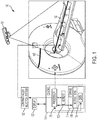
- FIG. 1 shows a scanner system 100, including a control device 110 for controlling a scanner 105.
- the scanner 105 can be an magnetic resonance (MR) scanner, such as a "MAGNETOM VIDA”TM scanner, a computed tomography (CT) scanner, such as a "SOMATOM CONFIDENCE RT Pro”TM CT Scanner, a PET scanner, such as the "BIOGRAPH HORIZON”TM PET/CT scanner, or an ultrasound scanner, such as the "ACUSON SC2000PRIME”TM cardiovascular ultrasound system, all sold by Siemens Medical Solutions USA, Inc. of Malvern, PA.
- MR magnetic resonance
- CT computed tomography
- PET scanner such as the "BIOGRAPH HORIZON”TM PET/CT scanner
- ultrasound scanner such as the "ACUSON SC2000PRIME”TM cardiovascular ultrasound system, all sold by Siemens Medical Solutions USA, Inc. of Malvern, PA.
- the scanner can include an automated contrast agent injection system 120 automatic control of the injection profile, as provided by "CARE CONTRAST” TM in the "SOMATOM” TM scanner by Siemens Medical Solutions USA, Inc. of Malvern, PA, where the contrast injector can be connected to the CT scanner, enabling synchronized injection and scanning.
- the control device 110 has a processor 111 using machine learning to predict a scanning protocol for contrast enhancement imaging an internal organ (not shown) of the subject based on the prediction.
- the processor 111 is configured (e.g., by software) for controlling the scanner 105 based on the predicted contrast agent amount, injection profile, and delay between injecting the contrast agent and performing the scan.
- the processor 111 can issue commands to the automated contrast agent injection system 120, to inject a selected dosage of CA according to the predicted injection protocol. These are only examples, and other scanner makes and models may be used.
- the processor 111 can have user input/output devices, such as a display 122, which can be a touch-screen capable of receiving user inputs and displaying outputs. Other input devices (e.g., keyboard or pointing device, not shown) may be included.
- the processor 111 can include an embedded processor, a computer, a microcontroller, an application specific integrated circuit (ASIC), a programmable gate array, or the like.
- the control device 110 includes a main memory 112, which can include a non-transitory, machine readable storage medium such as dynamic random access memory (DRAM).
- the secondary memory comprises a non-transitory, machine readable storage medium 114, such as a solid-state drive, hard disk drive (HDD) and/or removable storage drive, which can include a solid state memory, an optical disk drive, a flash drive, a magnetic tape drive, or the like.
- the non-transitory, machine readable storage medium 114 can include tangibly store therein computer software instructions 116 for causing the scanner 105 to perform various operations (described herein) and data 118.
- the injection system 120 can perform calibrated injections to patients, starting from a multi-dose solution of iodine, fluorodeoxyglucose (FDG), or other radiopharmaceuticals.
- the scanner 100 is not equipped with an automated injection system 120, in which case a separate injection system (not shown) may be used.
- some systems can include an external injection system (not shown), such as the "IRISTM" Radiopharmaceutical Multidose Injector sold by Comecer S.p.A. of Castel Bolognese, Italy.
- the injection system 120 has a wired or wireless communications link with the processor 111, for automatically transmitting dosage, contrast agent application protocol and scan delay to the injection system 120.
- the processor 111 receives a value of a scan delay from a regressor (e.g., neural network) 220, to be used between an injection of the contrast agent and a scan from the neural network.
- the processor waits for approximately a period of time according to the scan delay after the injecting, and initiates performing a computed tomography scan or magnetic resonance scan (using the scanner) after the waiting.
- the injection begins upon expiration of the scan delay.
- the injection is timed so that the injection straddles the time of peak contrast agent concentration in the organ of interest, and the mid-point of the injection coincides with the time of peak contrast agent concentration.
- the system 100 can include a two-dimensional (2D) or three-dimensional (3D) camera 101.
- the 2D or 3D camera 101 captures an image of the patient before the scanning.
- the image can be used to estimate one or more patient attributes, such as patient height or weight, used by the control device 110.
- FIG. 2 is a block diagram of a system for determining contrast agent application protocol and scan delay in real-time, based on a test bolus data or bolus tracking data, for immediate use in contrast enhanced scanning while the patient is still on the scanner bed.
- Contrast agent uptake in the human body can be modeled using a simulator implementing a multi-compartment model 212 for modeling flow of a contrast agent through a body and generating contrast enhancement data.
- the contrast propagation through each compartment in the model 212 can be represented through a set of coupled differential equations, which can be solved to obtain the contrast agent concentration at any given location as a function of time.
- the results of the model 212 depend on the patient internal parameters, which can be personalized to the patient's attributes 214 (age, body mass, height, pathological condition, cardiac output, etc.). Once the model 212 is suitably parametrized, the model 212 can then be computationally "inverted".
- this includes computing the initial contrast agent injection protocol that is used to obtain a desired contrast density curve at a given location. For instance, for scanning the liver, a desired contrast agent density curve at the liver can be input, and then the model can be inverted to compute the contrast agent administration protocol that should be followed, based on the contrast enhancement data and patient attributes.
- Numerical solutions of the differential equations characterizing the multi-compartment models 212 may be computationally demanding and time consuming, a trained regressor (neural network) 220 provides sufficient acceleration to determine the contrast agent application protocol 233 within the clinical workflow.
- the neural network 220 is a deep neural network.
- the neural network 220 is configured to perform support vector regression.
- the neural network 220 trained with contrast enhancement data 211 from the model 212 can generate a contrast agent administration protocol 223 about 80 times as fast as the numerical solution of the differential equations of the PBPK model 212.
- the trained neural network 220 can generate the contrast agent administration protocol 233 immediately, and the generated contrast agent administration protocol 233 can be implemented while the patient is still on the scanner bed.
- the regressor e.g., neural network
- the regressor 220 can generate the contrast agent application protocol 233 and scan delay 234 parameters corresponding to the desired contrast enhancement in any targeted organ or blood vessel.
- the personalized model parameters 211, 213, 214, 215 from the offline numerical solution stage become training input parameters to the contrast propagation regressor (e.g., neural network) 220.
- This regressor e.g., neural network
- an optimal contrast agent application protocol 233 is selected based on the patient-specific model parameters 232.
- CA administration protocol 233 and scan delay 234 One approach to achieve significant acceleration of determining the CA administration protocol 233 and scan delay 234 is through the use of machine learning algorithms.
- the regressor e.g., neural network
- the regressor learns the relationship between the inputs (CA administration curve of test bolus data or bolus tracking data 231 and patient attribute, such as 2D or 3D image 232 from camera 101) and the outputs (resulting contrast agent application protocol 233 and scan delay 234).
- a large database 210 of the inputs (multi-compartment model 212, contrast agent application protocols 213, patient attributes 214 and, in some embodiments, image quality 215) and outputs (contrast enhancement data 211, also referred to herein as "synthetic data") is used to train a machine learning system (regressor 220).
- the regressor 220 learns to determine the relationship between the inputs and outputs, to determine an optimum contrast agent application protocol 233 and scan delay 234 given the test bolus data or bolus tracking data 231 and 2D or 3D image 232 from camera 101.
- the regressor 220 is a deep neural network having a plurality of coefficients.
- the coefficients are machine-learned by inputting a plurality of patient parameters (attributes) 214 and a plurality of contrast agent injection protocols 213 to a simulator 212, simulating flow of a contrast agent through a plurality of patients' bodies using the simulator 212, and providing the contrast enhancement data 211 based on the simulating, for use in the neural network.
- a large training dataset 210 is used to cover the domain of patient attributes.
- the available medical image data sets from past patients may not be large enough to train the regressor 220.
- any combination of data obtained by methods (1) to (3) can be used to provide enough training data.
- the regressor 220 can include multiple models, each looking at the input-output relationship for a specific blood vessel compartment or organ.
- One example is the machine learning based fractional flow reserve (FFR) prediction model, which has shown high accuracy compared to the numerical solution of the differential equations of the underlying physics model, while providing an 80-fold acceleration in the computational run-time.
- FFR fractional flow reserve
- the machine learning model in regressor 220 can also take account of any constraints the injection system may impose on the contrast agent application protocol 233. For instance, the regressor 220 can accommodate limits placed on the peak injection rate, total volume injected, smoothness of the injection curve etc. For instance, if a constant injection rate is desired, the regressor 220 can produce a specific injection rate which would minimize the contrast agent volume, to get as close as possible to the desired contrast distribution at the target organ.
- the system in FIG. 2 provides model personalization using a data-driven approach.
- the patient attributes 214 and contrast agent administration protocols 213 are input to the multi-compartment model 212, which numerically solves the differential equations to generate contrast enhancement data 211, as indicated by dashed arrows.
- each image (of previous patients) can be augmented with a quantitative "image quality" metric 215.
- the operator can input a quality metric based on the image obtained from a computed tomography scan or magnetic resonance scan.
- the image quality metric 215 can either be computed algorithmically based on different image features (for instance, contrast), or annotated by a clinical team, or a combination of both.
- the contrast enhancement data 211, contrast agent application protocol 213, patient attributes 214, and in some cases, image quality 215 can then form the training dataset 210 to input to the regressor 220.
- the regressor 220 takes into account the combination of different patient attributes 214 (e.g., either input or estimated from 2D or 3D image 232 from camera 101), along with the image quality 215 (if available), contrast enhancement data 211, scan delay (i.e., time difference between injection and image acquisition) and other features from the test bolus data or bolus tracking data 231 to learn a functional mapping between the features from the test bolus or bolus tracking scan image 231 and contrast agent application protocol 233 and scan delay 234 providing the optimal image quality.
- the operator can use the machine learning to reduce the contrast agent amount of a subsequent computed tomography scan or magnetic resonance scan or increase an image contrast of the subsequent computed tomography scan or magnetic resonance scan based on the quality metric.
- the training data 210 can include the contrast enhancement data 211 (obtained from the multi-compartment model 212), contrast agent application protocol 213, patient attributes 214, and in some cases, image quality 215.
- contrast enhancement data 211 obtained from the multi-compartment model 212
- contrast agent application protocol 213, patient attributes 214 obtained from the multi-compartment model 212
- image quality 215. Once trained based on the database 210 of past patient image acquisitions and/or phantom data and/or synthetic data covering a wide range of patient attributes 214, regressor 220 can provide patient-specific contrast agent application protocol 233 and scan delay 234 for any given test bolus data or bolus tracking data 231 and patient attributes or 2D or 3D image 232.
- cardiac output can be estimated from a test bolus data or bolus tracking data 231, which can be input to regressor 220.
- Information acquired from the test bolus data or bolus tracking data 231 with additional patient attributes or 2D or 3D image data 232 for all the organs and vessels can enhance accuracy.
- the regressor 220 can be applied to a test bolus data or bolus tracking data 231 of a new patient.
- the test bolus data or bolus tracking data 231 can be performed with a low dose injection of the contrast agent.
- the information from the test bolus data or bolus tracking data 231 is combined with patient attributes 232 (which can be input directly or estimated based on a 2D or 3D image from camera 101) and input to the regressor 220 to find a contrast agent application protocol 233 and scan delay 234 to optimize the correlation between the contrast intensity at a given location and the patient attributes 214 during an imaging scan.
- Patient attributes (e.g., height, weight) 232 can be input directly, or in some embodiments, a 2D or 3D image of the patient (indicative of one or more attributes of the patient) is also captured using a digital camera 101.
- the input patient parameters 232 can be estimated based on the 2D or 3D image.
- the network or regressor 220 uses input patient attributes 232, along with a set of features computed on the test bolus data or bolus tracking data 231 to infer the patient-specific model parameters (e.g., the contrast agent application protocol 233 and scan delay 234).
- a 3D avatar mesh of the subject is formed based on a 2.5D or 3D image from the camera 101, as disclosed in US 2015/0213646 A1 (Appl. No.: 14/604,829, filed Jan. 26, 2015 ).
- the height or other spatial attribute of the patient can be determined from the 3D avatar mesh.
- a depth camera image of the subject is converted to a 3D point cloud.
- a plurality of anatomical landmarks are detected in the 3D point cloud.
- a 3D avatar mesh is initialized by aligning a template mesh to the 3D point cloud based on the detected anatomical landmarks.
- a personalized 3D avatar mesh of the subject is then generated by optimizing the 3D avatar mesh using a trained parametric deformable model (PDM).
- PDM parametric deformable model
- a physiologically based pharmacokinetic (PBPK) model 212 can simulate contrast agent propagation in the human body. Simplified effective models are provided for each organ, parametrized by a reduced set of parameters to address the forward model of contrast propagation, given the initial injection curve. An exemplary systems model is shown in FIG. 3 .
- model-based optimization can be used for selecting the contrast agent injection protocols.
- FIG. 3 shows an example of a multi-compartment model for blood and contrast agent flow through the body.
- FIG. 3 is a sample schematic diagram of a physiologically based pharmacokinetic (PBPK) model of a human body.
- the model can predict absorption, distribution, and metabolism of the contrast agent within the body, beginning with injection.
- each block (3, 8, 11, 14, 16, 20, 21, 23, 25, 28, 29, 32 and 36) represents an organ compartment
- each ellipse (1, 2, 4-7, 9-10, 12, 13, 15, 17-19, 22, 24, 26, 27, 30-31, 33-35, and 37) represents a blood vessel compartment.
- Table 1 lists the compartments of the model of FIG. 3 and their respective descriptions, according to one example.
- the compartments in Table 1 are numbered in the order in which they appear in FIG. 3 .
- the heart is represented by three separate compartments: the left heart, right heart, and heart muscle. Because of the negligible amount of perfusion occurring in left and right heart, they are assumed to be vessel compartments.
- Table 1 only includes the organs' names (except aorta), and the vessels are named with their compartment numbers (except aorta). Although the nodes of the model begin with the right heart (compartment No.
- the injection can be performed at any injection site (compartment), and the contrast agent flows to the remaining compartments in the order listed, and after the iliac vein (compartment No. 37) flows the right heart (compartment No. 1) and continues in order.
- TABLE 1 Estimated Blood Distribution in the Vascular System, Blood Flow Rate, and Capillary Volumes Used in PBPK Model Compartment Type Blood Flow Rate (mL/sec) Intravascular Volume (mL) Extracellular Volume (mL) 1.
- Right heart Vessel 29.0 180 0 2. Pulmonary artery Vessel 108.3 130 0 3. Lung parenchyma Organ 108.3 150 144 4. Pulmonary vein Vessel 108.3 160 0 5.
- the flows of contrast agent into and out of each organ, and changes in concentration within the organ can be expressed by a respective differential equation.
- the differential equations for each organ can indicate that blood flow rate out of the organ equals blood flow rate into the organ, while the rate of change in CA concentration in the organ varies with the blood flow rate through the organ and the difference between the input CA concentration and the output CA concentration.
- This set of differential equations is described in Sahbaee, Pooyan, et al. "The effect of contrast agent on radiation dose at CT: part I. Incorporation of contrast agent dynamics in anthropomorphic phantoms.” Radiology 283.3 (2017): 739-748 .
- the set of differential equations can be solved numerically, to predict absorption, distribution and metabolism. Numerical solutions for a large PBPK model, such as model 212, may be computationally expensive.
- the contrast agent flow in the model of FIG. 3 is described by approximately 300 differential equations.
- the computational models based on the solution of large sets of coupled differential equations have a long computational time.
- the differential equations for the model 212 are solved many (e.g., 10,000) times over the domain of contrast agent administration protocols 213 and patient attributes 214, to generate a large set of contrast enhancement data 211.
- This dataset 210 can be generated a single time, prior to training.
- the regressor 220 can generate contrast agent administration protocols 233 and scan delay 234 in real time during patient contrast enhanced image scanning.
- the 37-compartment model of FIG. 3 is just an example. Any multi-compartmented model can be used, in accordance with the desired accuracy and/or desired computation time and complexity.
- the model of FIG. 3 includes a single compartment for the small intestine and a single compartment for the large intestine.
- the small intestine and/or large intestine could be modeled as two or more compartments.
- the disclosed system can be applied for any organs with more than one input "vessel" (e.g., liver) and/or for any organ having more than one output vessel.
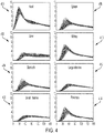
- FIG. 4 shows sets of contrast enhancement data 211 generated by the multi-compartmented model 212.
- Separate contrast enhancement data are provided for each organ.
- the data include several contrast enhancement curves for each of: heart 400, liver 402, stomach 404, small intestine 406, spleen 408, kidney 410, large intestine 412, and pancreas 414.
- the various curves for each organ correspond to different inputs (e.g., contrast agent application protocols 213 and/or patient attributes 214).
- the model can further include one or more lesion compartments connected to one or more organs and/or blood vessels.
- a model including a separate lesion compartment can be more realistically representative of patients.
- a lesion compartment 3a may be added to represent a tumor on a patient's lung.
- the training dataset 210 also includes a plurality of different contrast agent administration protocols 213.
- FIG 5 shows an example of a set 213 of contrast agent administration protocols 500-505.
- Each contrast agent administration protocols e.g., 500
- the contrast agent is injected at a constant rate for a first period, and then the injection stops.
- the amount of contrast agent injected per unit of time can vary. For example, the amount of contrast agent injected per unit of time can ramp up during a first period, remain constant during a second period, ramp down during a third period, and then remain at zero. This is only an example, and other injection profiles can be used.
- a neural network can be trained using "synthetic data" generated by numerical solution of the multi-compartment model.
- the training set includes a diverse group (e.g., 10,000) of patient examples covering the domain of patient characteristics (age, sex, weight, height, etc.) and contrast agent administration protocols.
- the synthetic data may be supplemented with clinical patient data and/or phantom data (e.g., XCAT phantom data) to ensure that the training set is sufficiently large.
- an application can use the neural network to generate imaging protocol parameters (contrast agent dosage, injection profile, and delay between injection and scan) in real-time conditions, enabling simple user workflows.
- a real-time test bolus or bolus tracking scan is performed using a low dosage of a contrast agent (CA), and a test bolus enhancement curve is generated.
- the test bolus enhancement curve from test bolus or bolus tracking scan 231 and the patient attributes or 2D or 3D image 232 are then input to the neural network 220, which generates the parameters of the contrast agent administration protocol 233 and the scan delay 234.
- the resulting imaging protocol maximizes contrast with a minimum contrast agent amount.
- the synthetic data generated by the multi-compartment PBPK model 212 can be used to feed and train a deep learning network or regressor 220 to predict the contrast agent injection function for a desired enhancement in different organs.
- the PBPK model can provide any desired number of contrast enhancement perfusion data as function of time, throughout the domain of patient characteristics, for training the contrast-enhancement prediction machine learning network.
- CA administration protocol 233 properly orchestrated with the scan parameters (e.g., scan timing) enhances medical imaging, maintains high image quality, for any medical scanner technology using contrast enhancement in clinical practice.
- scan parameters e.g., scan timing
- the regressor 220 is trained using samples throughout the domain of patient types (patient size, body mass index, etc.) the acquired images are of consistent quality regardless of patient characteristics. This also supports any downstream applications which use the medical images. For instance, in the cardiac use case, consistent gray values across patients will enable much more accurate determination of coronary centerline, and enable more accurate lumen segmentation.
- FIG. 6 is a schematic diagram of the system in its configuration for clinical use.
- the trained regressor 220 e.g., neural network
- the regressor 220 uses these inputs to accurately predict the cardiac output for individual patients, and consequently provide more precise individual contrast enhancement curves in different organs.
- the regressor 220 can provide respective contrast injection curves 233 (contrast agent application protocol) for the heart, spleen, liver, kidney, stomach, large intestine, small intestine, and pancreas.
- the regressor 220 also provides a contrast enhancement curve 600, from which the maximum contrast agent concentration 602 and the scan delay 234 corresponding to the maximum concentration value 602 can be determined. These outputs are then used immediately for contrast imaging while the patient is still on the bed.
- the quantity of contrast agent, contrast agent administration protocol, and the scan delay are based on the outputs of the regressor 220.
- the computation time of solving the differential equations of the PBPK model 212 does not pose an impediment to patient-specific scan protocol generation using the regressor 220.
- the regressor 220 uses the previously trained regressor 220 and fine-tuning the different patient-specific parameters 232 (e.g., cardiac output, age, sex, organ and vessel sizes), injection protocol parameters (e.g., iodine concentration, volume, and injection rate) 233 and scan delay 234, the system can collect numerous contrast enhancement data in different organs.
- the inputs to the PBPK model 212 are patient specific, they are independent of the neural network 220 and independent of the imaging scanner make and model.
- a training set 210 including synthetic data from the PBPK model 212 is generated, the same training set 210 can be used to determine the injection protocol for any scanner. Also, the same training set can be used to train a variety of machine learning systems (e.g., a variety of deep neural networks) to generate the injection protocols.
- the network or regressor 220 can be used in a variety of embodiments. For example,
- the system includes a non-transitory machine readable storage medium 114 containing a plurality of different "desired contrast distributions" for each organ.
- the system can include a regressor 220 configured for receiving the test bolus or bolus tracking enhancement curve 231 and fetching the desired contrast distribution ( FIG. 4 ) corresponding to the organ of interest, and generating a respective contrast agent administration protocol (e.g., injection function).
- the processor 111 system can provide touch-based interfaces for displaying data and prompts, and for receiving user inputs.
- a touch screen display 122 FIG. 1
- the system can provide voice-activated or natural language interfaces, so the operator can speak voice commands to instruct the system (e.g., to acquire a coronary image).
- the system prompts the operator for approval of an estimate of the dose and the generated injection curve, before automatically commencing injection.
- the system 100 is configured to receive an operator input rating the quality of each scan upon completion.
- the system 100 is configured to incorporate the rating data for continuously learning the best injection protocols to minimize dose and contrast volume, while maximizing image quality.
- the learning machine of regressor 220 can learn from the difference between the prediction results and real data.
- the system 100 is configured to prompt the operator to select from one or more past cases in which the output image contrast was high.
- the network or regressor 220 calibrates or adapts itself to new patients based on the selected past case(s), to obtain images having similar quality or better quality.
- a summary of the machine learning from a plurality of scanner systems can be collected periodically and used to identify best practices, which can be disseminated to improve network or regressor 220 performance over the installed fleet of scanners.
- the methods and system described herein may be at least partially embodied in the form of computer-implemented processes and apparatus for practicing those processes.
- the disclosed methods may also be at least partially embodied in the form of tangible, non-transitory machine readable storage media encoded with computer program code.
- the media may include, for example, RAMs, ROMs, CD-ROMs, DVD-ROMs, BD-ROMs, hard disk drives, flash memories, or any other non-transitory machine-readable storage medium, wherein, when the computer program code is loaded into and executed by a computer, the computer becomes an apparatus for practicing the method.
- the methods may also be at least partially embodied in the form of a computer into which computer program code is loaded and/or executed, such that, the computer becomes a special purpose computer for practicing the methods.
- the computer program code segments configure the processor to create specific logic circuits.
- the methods may alternatively be at least partially embodied in a digital signal processor formed of application specific integrated circuits for performing the methods.
Landscapes
- Health & Medical Sciences (AREA)
- Engineering & Computer Science (AREA)
- Life Sciences & Earth Sciences (AREA)
- Physics & Mathematics (AREA)
- Medical Informatics (AREA)
- General Health & Medical Sciences (AREA)
- Biomedical Technology (AREA)
- Public Health (AREA)
- Biophysics (AREA)
- Molecular Biology (AREA)
- Animal Behavior & Ethology (AREA)
- Heart & Thoracic Surgery (AREA)
- Veterinary Medicine (AREA)
- Theoretical Computer Science (AREA)
- Surgery (AREA)
- Pathology (AREA)
- Nuclear Medicine, Radiotherapy & Molecular Imaging (AREA)
- High Energy & Nuclear Physics (AREA)
- Radiology & Medical Imaging (AREA)
- Optics & Photonics (AREA)
- Artificial Intelligence (AREA)
- General Physics & Mathematics (AREA)
- Evolutionary Computation (AREA)
- Mathematical Physics (AREA)
- General Engineering & Computer Science (AREA)
- Software Systems (AREA)
- Computing Systems (AREA)
- Data Mining & Analysis (AREA)
- Computational Linguistics (AREA)
- Dentistry (AREA)
- Primary Health Care (AREA)
- Epidemiology (AREA)
- Vascular Medicine (AREA)
- Oral & Maxillofacial Surgery (AREA)
- Computer Vision & Pattern Recognition (AREA)
- Signal Processing (AREA)
- Bioinformatics & Cheminformatics (AREA)
- Pulmonology (AREA)
- Chemical & Material Sciences (AREA)
- Medicinal Chemistry (AREA)
Description
- This disclosure relates to medical imaging generally, and more specifically to contrast-enhanced imaging.
- Dynamic contrast-enhanced (DCE) imaging provides dynamic information about the flow of an injected contrast agent through blood vessels to different tissues. Tissues with substantially different blood flow rates appear in a DCE image with contrasting tones. For example, DCE enables analysis of blood vessels generated by a brain tumor. The concentration of the contrast agent is measured as it passes from the blood vessels to the extracellular space of the tissue and as it goes back to the blood vessels, and magnetic resonance (MR) or computed tomography (CT) images are reconstructed from the concentration data.
- The amount of contrast agent injected into the patient can be reduced for patient safety. A tradeoff can be made between reduction in the amount of contrast agent injected into the patient and contrast enhancement
- Document
US2018032841 A1 may be considered to disclose a system comprising: a non-transitory, machine readable storage medium storing contrast enhancement data, at least one patient attribute of a patient and at least one processor configured to generate a protocol, based on the contrast enhancement data and the at least one patient attribute; and also to disclose the corresponding method. - The invention is defined by the claims. According to a first aspect of the disclosure, a method comprises inputting contrast enhancement data for at least one organ of a patient, at least one patient attribute of the patient, and a test bolus data or bolus tracking data to a regressor; receiving a contrast agent administration protocol from the regressor, based on the contrast enhancement data, the at least one patient attribute and the test bolus or bolus tracking data; and injecting a contrast agent into the patient according to the received contrast agent administration protocol.
- Preferred is a method, wherein the contrast agent administration protocol includes at least one of the group consisting of a contrast agent amount and a contrast agent injection function. The method can further comprise: receiving a value of a scan delay between an injection of the contrast agent and a scan, waiting for at least a period of time according to the scan delay after the injecting, and performing a computed tomography scan or magnetic resonance scan after the waiting. Further, the method can comprise: inputting a quality metric based on the computed tomography scan or magnetic resonance scan, and using machine learning to reduce the contrast agent amount of a subsequent computed tomography scan or magnetic resonance scan or increase an image contrast of the subsequent computed tomography scan or magnetic resonance scan based on the quality metric.
- Further, a method is preferred, wherein the contrast agent injection function includes a respective contrast agent injection function for each of a plurality of organs.
- Preferred is a method, wherein the regressor is trained by: inputting a plurality of patient parameters and a plurality of injection protocols to a simulator; simulating flow of a contrast agent through a plurality of patients' bodies using the simulator; and providing a plurality of contrast enhancement data based on the simulating. Further, a method is preferred, wherein the regressor performs support vector regression. Preferred is a method, further comprising providing additional contrast enhancement data based on measured patient data or phantom data. The simulator can have a multi-compartment model relating the contrast agent amount and a distribution of the contrast agent at a plurality of different locations within a body of the patient as a function of time, in particular the multi-compartment model can further comprise a compartment corresponding to a lesion.
- Preferred is a method, wherein the contrast agent injection function is selected from a plurality of previously stored contrast distributions for each of a plurality of organs.
- Further, a method is preferred, wherein the patient attribute includes at least one of the group consisting of a patient weight, a patient surface area, a patient age, a patient height or a marker. The method can further comprise: capturing a depth image of the patient; and estimating the patient attribute based on the depth image and based on a computational phantom or a database containing previously collected patient data.
- According to a second aspect of the disclosure, a system comprises a simulator for modeling flow of a contrast agent through a body and generating contrast enhancement data. A non-transitory, machine readable storage medium stores the contrast enhancement data, at least one patient attribute of a patient, and a test bolus or bolus tracking data of the patient. At least one processor includes a regressor configured to generate a contrast agent administration protocol, based on the contrast enhancement data and the at least one patient attribute.
- Preferred is a system, wherein the regressor includes a neural network.
- Preferred is further a system, wherein the simulator has a multi-compartment model relating the contrast agent amount and a distribution of the contrast agent at a plurality of different locations within the patient as a function of time, in particular wherein the multi-compartment model has respective compartments for at least one organ and at least one blood vessel of the patient. Further, a system is preferred, wherein the regressor has a plurality of coefficients machine-learned by inputting a plurality of patient parameters and a plurality of injection protocols to a simulator; by simulating flow of a contrast agent through a plurality of patients' bodies using the simulator; and by providing the contrast enhancement data based on the simulating, for use in the regressor.
- Preferred is further a system, wherein the regressor is further configured to generate a value of a scan delay between an injection of the contrast agent in the patient and a scan, and the system further comprises a computed tomography scanner or a magnetic resonance scanner for capturing the test bolus data or bolus tracking data and for capturing medical image data with the injection of the contrast agent and a scan separated by the scan delay.
- Preferred is a system, wherein the regressor performs support vector regression.
- According to a third aspect of the disclosure. a non-transitory, machine-readable storage medium is encoded with instructions for controlling a processor, such that when the processor executes the instructions, the processor performs a method comprising: simulating flow of a contrast agent through a body and generating contrast enhancement data from the simulating; inputting at least one patient attribute of a patient to a regressor trained using the contrast enhancement data; and using the regressor to generate a scan delay between an injection of a contrast agent and a scan, such that performance of the scan after the injection and the scan delay captures an image of an organ with a peak contrast agent concentration in the organ. Preferred is a non-transitory, machine-readable storage medium, wherein the simulating includes using a multi-compartment model relating a contrast agent amount and a distribution of the contrast agent at a plurality of different locations within a body of the patient as a function of time. The multi-compartment model can have respective compartments for at least two of at least one organ and at least one blood vessel of a patient, in particular the method can further comprise additional training of the regressor using at least one of functional test data or phantom data. The system according the second aspect of the disclosure and the non-transitory, machine-readable storage medium according the third aspect of the disclosure respectively are configured to perform a method according to the first aspect of the disclosure.
-
-
FIG. 1 is a schematic diagram of a system including machine-learning based contrast agent administration, according to an exemplary embodiment. -
FIG. 2 is a block diagram of the system shown inFIG. 1 . -
FIG. 3 is a schematic diagram of the multi-compartment model ofFIG. 2 . -
FIG. 4 shows contrast enhancement data provided by the multi-compartment model ofFIG. 3 . -
FIG. 5 shows contrast agent administration protocols input to the multi-compartment model ofFIG. 2 . -
FIG. 6 is an information flow diagram for the system ofFIG. 1 . - This description of the exemplary embodiments is intended to be read in connection with the accompanying drawings, which are to be considered part of the entire written description.
- This disclosure can provide fast, patient-specific estimation of an optimal contrast injection protocol, for organ-specific imaging applications. For a given amount of contrast agent (CA), the system and method can provide the greatest image contrast. Alternatively, for a given target contrast, the system and method can minimize the amount of contrast agent injected into the patient. The system can determine and implement an optimal, patient-specific contrast agent administration protocol and scan delay (i.e., delay between contrast agent injection and scanning) corresponding to the patient's cardiac output. The system and methods may lead to better image quality at significantly lower doses of contrast agent. The scan times can also be reduced significantly, while simultaneously maintaining high image quality.
-
FIG. 1 shows ascanner system 100, including acontrol device 110 for controlling ascanner 105. Thescanner 105 can be an magnetic resonance (MR) scanner, such as a "MAGNETOM VIDA"™ scanner, a computed tomography (CT) scanner, such as a "SOMATOM CONFIDENCE RT Pro"™ CT Scanner, a PET scanner, such as the "BIOGRAPH HORIZON"™ PET/CT scanner, or an ultrasound scanner, such as the "ACUSON SC2000PRIME"™ cardiovascular ultrasound system, all sold by Siemens Medical Solutions USA, Inc. of Malvern, PA. The scanner can include an automated contrastagent injection system 120 automatic control of the injection profile, as provided by "CARE CONTRAST" ™ in the "SOMATOM" ™ scanner by Siemens Medical Solutions USA, Inc. of Malvern, PA, where the contrast injector can be connected to the CT scanner, enabling synchronized injection and scanning. - The
control device 110 has aprocessor 111 using machine learning to predict a scanning protocol for contrast enhancement imaging an internal organ (not shown) of the subject based on the prediction. Theprocessor 111 is configured (e.g., by software) for controlling thescanner 105 based on the predicted contrast agent amount, injection profile, and delay between injecting the contrast agent and performing the scan. Theprocessor 111 can issue commands to the automated contrastagent injection system 120, to inject a selected dosage of CA according to the predicted injection protocol. These are only examples, and other scanner makes and models may be used. Theprocessor 111 can have user input/output devices, such as adisplay 122, which can be a touch-screen capable of receiving user inputs and displaying outputs. Other input devices (e.g., keyboard or pointing device, not shown) may be included. - The
processor 111 can include an embedded processor, a computer, a microcontroller, an application specific integrated circuit (ASIC), a programmable gate array, or the like. Thecontrol device 110 includes amain memory 112, which can include a non-transitory, machine readable storage medium such as dynamic random access memory (DRAM). The secondary memory comprises a non-transitory, machinereadable storage medium 114, such as a solid-state drive, hard disk drive (HDD) and/or removable storage drive, which can include a solid state memory, an optical disk drive, a flash drive, a magnetic tape drive, or the like. The non-transitory, machinereadable storage medium 114 can include tangibly store thereincomputer software instructions 116 for causing thescanner 105 to perform various operations (described herein) anddata 118. - The
injection system 120 can perform calibrated injections to patients, starting from a multi-dose solution of iodine, fluorodeoxyglucose (FDG), or other radiopharmaceuticals. In some embodiments, thescanner 100 is not equipped with anautomated injection system 120, in which case a separate injection system (not shown) may be used. For example, some systems can include an external injection system (not shown), such as the "IRIS™" Radiopharmaceutical Multidose Injector sold by Comecer S.p.A. of Castel Bolognese, Italy. In some embodiments, theinjection system 120 has a wired or wireless communications link with theprocessor 111, for automatically transmitting dosage, contrast agent application protocol and scan delay to theinjection system 120. In some embodiments, theprocessor 111 receives a value of a scan delay from a regressor (e.g., neural network) 220, to be used between an injection of the contrast agent and a scan from the neural network. The processor waits for approximately a period of time according to the scan delay after the injecting, and initiates performing a computed tomography scan or magnetic resonance scan (using the scanner) after the waiting. In some embodiments, the injection begins upon expiration of the scan delay. In other embodiments, the injection is timed so that the injection straddles the time of peak contrast agent concentration in the organ of interest, and the mid-point of the injection coincides with the time of peak contrast agent concentration. - The
system 100 can include a two-dimensional (2D) or three-dimensional (3D)camera 101. In some embodiments, the 2D or3D camera 101 captures an image of the patient before the scanning. The image can be used to estimate one or more patient attributes, such as patient height or weight, used by thecontrol device 110. -
FIG. 2 is a block diagram of a system for determining contrast agent application protocol and scan delay in real-time, based on a test bolus data or bolus tracking data, for immediate use in contrast enhanced scanning while the patient is still on the scanner bed. - Contrast agent uptake in the human body can be modeled using a simulator implementing a
multi-compartment model 212 for modeling flow of a contrast agent through a body and generating contrast enhancement data. The contrast propagation through each compartment in themodel 212 can be represented through a set of coupled differential equations, which can be solved to obtain the contrast agent concentration at any given location as a function of time. The results of themodel 212 depend on the patient internal parameters, which can be personalized to the patient's attributes 214 (age, body mass, height, pathological condition, cardiac output, etc.). Once themodel 212 is suitably parametrized, themodel 212 can then be computationally "inverted". In some embodiments, this includes computing the initial contrast agent injection protocol that is used to obtain a desired contrast density curve at a given location. For instance, for scanning the liver, a desired contrast agent density curve at the liver can be input, and then the model can be inverted to compute the contrast agent administration protocol that should be followed, based on the contrast enhancement data and patient attributes. - Numerical solutions of the differential equations characterizing the
multi-compartment models 212 may be computationally demanding and time consuming, a trained regressor (neural network) 220 provides sufficient acceleration to determine the contrastagent application protocol 233 within the clinical workflow. In some embodiments, theneural network 220 is a deep neural network. In some embodiments, theneural network 220 is configured to perform support vector regression. For example, in some cases, theneural network 220 trained withcontrast enhancement data 211 from themodel 212 can generate a contrast agent administration protocol 223 about 80 times as fast as the numerical solution of the differential equations of thePBPK model 212. In the clinical phase, following the test bolus orbolus tracking scan 231, the trainedneural network 220 can generate the contrastagent administration protocol 233 immediately, and the generated contrastagent administration protocol 233 can be implemented while the patient is still on the scanner bed. - Combining machine learning techniques with physiological based compartmental modeling and real-time test bolus or bolus tracking curves 231 from the
scanner 100, the regressor (e.g., neural network) 220 can generate the contrastagent application protocol 233 and scandelay 234 parameters corresponding to the desired contrast enhancement in any targeted organ or blood vessel. - The
personalized model parameters contrast enhancement data 211 defining the relationship between the injected contrast volume and its distribution at different locations as a function of time. Then, given the organ (or region) of interest to be imaged, an optimal contrast agent application protocol 233 (including a CA injection curve) is selected based on the patient-specific model parameters 232. - One approach to achieve significant acceleration of determining the
CA administration protocol 233 and scandelay 234 is through the use of machine learning algorithms. In this approach, the regressor (e.g., neural network) 220 learns the relationship between the inputs (CA administration curve of test bolus data orbolus tracking data 231 and patient attribute, such as 2D or3D image 232 from camera 101) and the outputs (resulting contrastagent application protocol 233 and scan delay 234). Alarge database 210 of the inputs (multi-compartment model 212, contrastagent application protocols 213, patient attributes 214 and, in some embodiments, image quality 215) and outputs (contrast enhancement data 211, also referred to herein as "synthetic data") is used to train a machine learning system (regressor 220). Theregressor 220 learns to determine the relationship between the inputs and outputs, to determine an optimum contrastagent application protocol 233 and scandelay 234 given the test bolus data orbolus tracking data 3D image 232 fromcamera 101. - In some embodiments, the
regressor 220 is a deep neural network having a plurality of coefficients. The coefficients are machine-learned by inputting a plurality of patient parameters (attributes) 214 and a plurality of contrastagent injection protocols 213 to asimulator 212, simulating flow of a contrast agent through a plurality of patients' bodies using thesimulator 212, and providing thecontrast enhancement data 211 based on the simulating, for use in the neural network. - In various embodiments, the following different approaches can be used to generate the database:
- 1) The
training data 210 can be generated by multiple runs of numerically solving the differential equations of themulti-compartment model 212, using different sampling methods to generate random inputs, model parameters and the corresponding outputs. The different model parameters can be sampled (e.g., using different random number generators, or using other sampling methods) to span the range of physiological interest. - (2) Data acquired using controlled experiments on phantom datasets, where organs with different properties are prepared and imaged.
- (3) Actual medical images acquired from past patients.
- A
large training dataset 210 is used to cover the domain of patient attributes. The available medical image data sets from past patients may not be large enough to train theregressor 220. According to some embodiments, any combination of data obtained by methods (1) to (3) can be used to provide enough training data. - In some embodiments, the
regressor 220 can include multiple models, each looking at the input-output relationship for a specific blood vessel compartment or organ. One example is the machine learning based fractional flow reserve (FFR) prediction model, which has shown high accuracy compared to the numerical solution of the differential equations of the underlying physics model, while providing an 80-fold acceleration in the computational run-time. - The machine learning model in
regressor 220 can also take account of any constraints the injection system may impose on the contrastagent application protocol 233. For instance, theregressor 220 can accommodate limits placed on the peak injection rate, total volume injected, smoothness of the injection curve etc. For instance, if a constant injection rate is desired, theregressor 220 can produce a specific injection rate which would minimize the contrast agent volume, to get as close as possible to the desired contrast distribution at the target organ. - The system in
FIG. 2 provides model personalization using a data-driven approach. The patient attributes 214 and contrastagent administration protocols 213 are input to themulti-compartment model 212, which numerically solves the differential equations to generatecontrast enhancement data 211, as indicated by dashed arrows. - During the model personalization, each image (of previous patients) can be augmented with a quantitative "image quality"
metric 215. The operator can input a quality metric based on the image obtained from a computed tomography scan or magnetic resonance scan. Theimage quality metric 215 can either be computed algorithmically based on different image features (for instance, contrast), or annotated by a clinical team, or a combination of both. Thecontrast enhancement data 211, contrastagent application protocol 213, patient attributes 214, and in some cases,image quality 215 can then form thetraining dataset 210 to input to theregressor 220. Theregressor 220 takes into account the combination of different patient attributes 214 (e.g., either input or estimated from 2D or3D image 232 from camera 101), along with the image quality 215 (if available),contrast enhancement data 211, scan delay (i.e., time difference between injection and image acquisition) and other features from the test bolus data orbolus tracking data 231 to learn a functional mapping between the features from the test bolus or bolustracking scan image 231 and contrastagent application protocol 233 and scandelay 234 providing the optimal image quality. The operator can use the machine learning to reduce the contrast agent amount of a subsequent computed tomography scan or magnetic resonance scan or increase an image contrast of the subsequent computed tomography scan or magnetic resonance scan based on the quality metric. - For each organ of each patient, the
training data 210 can include the contrast enhancement data 211 (obtained from the multi-compartment model 212), contrastagent application protocol 213, patient attributes 214, and in some cases,image quality 215. Once trained based on thedatabase 210 of past patient image acquisitions and/or phantom data and/or synthetic data covering a wide range of patient attributes 214,regressor 220 can provide patient-specific contrastagent application protocol 233 and scandelay 234 for any given test bolus data orbolus tracking data 231 and patient attributes or 2D or3D image 232. - One of the challenges in modeling the accurate patient-specific contrast agent distribution in individual patients is the estimation of cardiac output in real time. During the
clinical phase 230, cardiac output can be estimated from a test bolus data orbolus tracking data 231, which can be input toregressor 220. Information acquired from the test bolus data orbolus tracking data 231 with additional patient attributes or 2D or3D image data 232 for all the organs and vessels can enhance accuracy. Once theregressor 220 is trained, theregressor 220 can be applied to a test bolus data orbolus tracking data 231 of a new patient. The test bolus data orbolus tracking data 231 can be performed with a low dose injection of the contrast agent. In some embodiments, for each clinical phase patient, the information from the test bolus data orbolus tracking data 231 is combined with patient attributes 232 (which can be input directly or estimated based on a 2D or 3D image from camera 101) and input to theregressor 220 to find a contrastagent application protocol 233 and scandelay 234 to optimize the correlation between the contrast intensity at a given location and the patient attributes 214 during an imaging scan. - Patient attributes (e.g., height, weight) 232 can be input directly, or in some embodiments, a 2D or 3D image of the patient (indicative of one or more attributes of the patient) is also captured using a
digital camera 101. Theinput patient parameters 232 can be estimated based on the 2D or 3D image. The network orregressor 220 then uses input patient attributes 232, along with a set of features computed on the test bolus data orbolus tracking data 231 to infer the patient-specific model parameters (e.g., the contrastagent application protocol 233 and scan delay 234). - In some embodiments, a 3D avatar mesh of the subject is formed based on a 2.5D or 3D image from the
camera 101, as disclosed inUS 2015/0213646 A1 (Appl. No.:14/604,829, filed Jan. 26, 2015 - A physiologically based pharmacokinetic (PBPK)
model 212 can simulate contrast agent propagation in the human body. Simplified effective models are provided for each organ, parametrized by a reduced set of parameters to address the forward model of contrast propagation, given the initial injection curve. An exemplary systems model is shown inFIG. 3 . - In some embodiments, model-based optimization can be used for selecting the contrast agent injection protocols. For example,
FIG. 3 shows an example of a multi-compartment model for blood and contrast agent flow through the body.FIG. 3 is a sample schematic diagram of a physiologically based pharmacokinetic (PBPK) model of a human body. The model can predict absorption, distribution, and metabolism of the contrast agent within the body, beginning with injection. InFIG. 3 , each block (3, 8, 11, 14, 16, 20, 21, 23, 25, 28, 29, 32 and 36) represents an organ compartment, and each ellipse (1, 2, 4-7, 9-10, 12, 13, 15, 17-19, 22, 24, 26, 27, 30-31, 33-35, and 37) represents a blood vessel compartment. - Table 1 lists the compartments of the model of
FIG. 3 and their respective descriptions, according to one example. The compartments in Table 1 are numbered in the order in which they appear inFIG. 3 . In the compartmental model of Table 1 andFIG. 3 , the heart is represented by three separate compartments: the left heart, right heart, and heart muscle. Because of the negligible amount of perfusion occurring in left and right heart, they are assumed to be vessel compartments. Table 1 only includes the organs' names (except aorta), and the vessels are named with their compartment numbers (except aorta). Although the nodes of the model begin with the right heart (compartment No. 1), the injection can be performed at any injection site (compartment), and the contrast agent flows to the remaining compartments in the order listed, and after the iliac vein (compartment No. 37) flows the right heart (compartment No. 1) and continues in order.TABLE 1 Estimated Blood Distribution in the Vascular System, Blood Flow Rate, and Capillary Volumes Used in PBPK Model Compartment Type Blood Flow Rate (mL/sec) Intravascular Volume (mL) Extracellular Volume (mL) 1. Right heart Vessel 29.0 180 0 2. Pulmonary artery Vessel 108.3 130 0 3. Lung parenchyma Organ 108.3 150 144 4. Pulmonary vein Vessel 108.3 160 0 5. Left heart Vessel 108.3 180 0 6. Aorta Vessel 108.3 100 0 7. Carotid artery Vessel 16.3 20 0 8. Head Organ 16.3 37 484 9. Superior jugular vein Vessel 16.3 80 0 10. Subclavian aorta Vessel 5.4 20 0 11. Upper extremity Organ 5.4 12 2751 12. Superior vena cava Vessel 2.7 40 0 13. Superior vena cava Vessel 2.7 40 0 14. Heart muscle Organ 4.3 10 103 15. Bronchial artery Vessel 82.3 100 0 16. Lung nonparenchyma Organ 2.2 5 144 17. Descending aorta Vessel 80.2 100 0 18. Hepatic artery Vessel 7.5 20 0 19. Mesenteric artery Vessel 15.5 20 0 20. Small intestine Organ 15.6 20 322 21. Colon Organ 15.6 14 218 22. Celiac artery Vessel 8.2 20 0 23. Stomach Organ 8.25 10 62 24. Portal vein Vessel 23.8 100 0 25. Liver Organ 7.5 71 524 26. Renal vein Vessel 31.4 100 0 27. Inferior vena cava Vessel 80.1 800 0 28. Pancreas Organ 8.25 2 12 29. Spleen Organ 8.25 6 37 30. Abdominal aorta Vessel 48.7 80 0 31. Renal artery Vessel 23.8 20 0 32. Kidney Organ 23.8 54 89 33. Renal vein Vessel 23.8 100 0 34. Inferior vena cava Vessel 48.7 700 0 35. Iliac artery Vessel 24.9 200 0 36. Trunk and lower extremities Organ 24.9 57 11002 37. Iliac vein Vessel 24.9 1000 0 - The flows of contrast agent into and out of each organ, and changes in concentration within the organ, can be expressed by a respective differential equation. For example, the differential equations for each organ can indicate that blood flow rate out of the organ equals blood flow rate into the organ, while the rate of change in CA concentration in the organ varies with the blood flow rate through the organ and the difference between the input CA concentration and the output CA concentration. This set of differential equations is described in Sahbaee, Pooyan, et al. "The effect of contrast agent on radiation dose at CT: part I. Incorporation of contrast agent dynamics in anthropomorphic phantoms." Radiology 283.3 (2017): 739-748. The set of differential equations can be solved numerically, to predict absorption, distribution and metabolism. Numerical solutions for a large PBPK model, such as
model 212, may be computationally expensive. For example, the contrast agent flow in the model ofFIG. 3 is described by approximately 300 differential equations. - The computational models based on the solution of large sets of coupled differential equations have a long computational time. In some embodiments, the differential equations for the
model 212 are solved many (e.g., 10,000) times over the domain of contrastagent administration protocols 213 and patient attributes 214, to generate a large set ofcontrast enhancement data 211. Thisdataset 210 can be generated a single time, prior to training. Once theregressor 220 is trained, theregressor 220 can generate contrastagent administration protocols 233 and scandelay 234 in real time during patient contrast enhanced image scanning. - The 37-compartment model of
FIG. 3 is just an example. Any multi-compartmented model can be used, in accordance with the desired accuracy and/or desired computation time and complexity. For example, the model ofFIG. 3 includes a single compartment for the small intestine and a single compartment for the large intestine. In other embodiments, the small intestine and/or large intestine could be modeled as two or more compartments. Further, the disclosed system can be applied for any organs with more than one input "vessel" (e.g., liver) and/or for any organ having more than one output vessel. - For example,
FIG. 4 shows sets ofcontrast enhancement data 211 generated by themulti-compartmented model 212. Separate contrast enhancement data are provided for each organ. For example, the data include several contrast enhancement curves for each of:heart 400,liver 402,stomach 404,small intestine 406,spleen 408,kidney 410,large intestine 412, andpancreas 414. The various curves for each organ correspond to different inputs (e.g., contrastagent application protocols 213 and/or patient attributes 214). - In some embodiments, to more accurately model the contrast enhancement curves in both healthy organs and in organs with pathology, the model can further include one or more lesion compartments connected to one or more organs and/or blood vessels. A model including a separate lesion compartment can be more realistically representative of patients. For example, referring again to
FIG. 3 , a lesion compartment 3a may be added to represent a tumor on a patient's lung. - The
training dataset 210 also includes a plurality of different contrastagent administration protocols 213.FIG 5 shows an example of aset 213 of contrast agent administration protocols 500-505. Each contrast agent administration protocols (e.g., 500) has a respectively different amount of contrast agent (e.g., iodine) injected per unit of time, as a function of time during injection. In the exemplary contrastagent administration protocols 213 ofFIG. 5 , the contrast agent is injected at a constant rate for a first period, and then the injection stops. In other embodiments, the amount of contrast agent injected per unit of time can vary. For example, the amount of contrast agent injected per unit of time can ramp up during a first period, remain constant during a second period, ramp down during a third period, and then remain at zero. This is only an example, and other injection profiles can be used. - Some embodiments of this disclosure use a machine-learning-based framework of high computational efficiency. A neural network can be trained using "synthetic data" generated by numerical solution of the multi-compartment model. The training set includes a diverse group (e.g., 10,000) of patient examples covering the domain of patient characteristics (age, sex, weight, height, etc.) and contrast agent administration protocols. The synthetic data may be supplemented with clinical patient data and/or phantom data (e.g., XCAT phantom data) to ensure that the training set is sufficiently large. Once the neural network is trained, an application can use the neural network to generate imaging protocol parameters (contrast agent dosage, injection profile, and delay between injection and scan) in real-time conditions, enabling simple user workflows. A real-time test bolus or bolus tracking scan is performed using a low dosage of a contrast agent (CA), and a test bolus enhancement curve is generated. The test bolus enhancement curve from test bolus or
bolus tracking scan 231 and the patient attributes or 2D or3D image 232 are then input to theneural network 220, which generates the parameters of the contrastagent administration protocol 233 and thescan delay 234. The resulting imaging protocol maximizes contrast with a minimum contrast agent amount. - The synthetic data generated by the
multi-compartment PBPK model 212 can be used to feed and train a deep learning network orregressor 220 to predict the contrast agent injection function for a desired enhancement in different organs. The PBPK model can provide any desired number of contrast enhancement perfusion data as function of time, throughout the domain of patient characteristics, for training the contrast-enhancement prediction machine learning network. - Optimization of
CA administration protocol 233 properly orchestrated with the scan parameters (e.g., scan timing) enhances medical imaging, maintains high image quality, for any medical scanner technology using contrast enhancement in clinical practice. Because theregressor 220 is trained using samples throughout the domain of patient types (patient size, body mass index, etc.) the acquired images are of consistent quality regardless of patient characteristics. This also supports any downstream applications which use the medical images. For instance, in the cardiac use case, consistent gray values across patients will enable much more accurate determination of coronary centerline, and enable more accurate lumen segmentation. -
FIG. 6 is a schematic diagram of the system in its configuration for clinical use. The trained regressor 220 (e.g., neural network) receives the real time test bolus orbolus tracking data 231 and a 2D or3D image 232 fromcamera 101 as the inputs. Theregressor 220 uses these inputs to accurately predict the cardiac output for individual patients, and consequently provide more precise individual contrast enhancement curves in different organs. For example, as shown inFIG. 6 , theregressor 220 can provide respective contrast injection curves 233 (contrast agent application protocol) for the heart, spleen, liver, kidney, stomach, large intestine, small intestine, and pancreas. Theregressor 220 also provides acontrast enhancement curve 600, from which the maximumcontrast agent concentration 602 and thescan delay 234 corresponding to themaximum concentration value 602 can be determined. These outputs are then used immediately for contrast imaging while the patient is still on the bed. The quantity of contrast agent, contrast agent administration protocol, and the scan delay (relative to the beginning of injection) are based on the outputs of theregressor 220. - Because the
PBPK model 212 is used during training (but not during real-time clinical use), the computation time of solving the differential equations of thePBPK model 212 does not pose an impediment to patient-specific scan protocol generation using theregressor 220. Using the previously trainedregressor 220 and fine-tuning the different patient-specific parameters 232 (e.g., cardiac output, age, sex, organ and vessel sizes), injection protocol parameters (e.g., iodine concentration, volume, and injection rate) 233 and scandelay 234, the system can collect numerous contrast enhancement data in different organs. - Additionally, although the inputs to the
PBPK model 212 are patient specific, they are independent of theneural network 220 and independent of the imaging scanner make and model. Once atraining set 210 including synthetic data from thePBPK model 212 is generated, the same training set 210 can be used to determine the injection protocol for any scanner. Also, the same training set can be used to train a variety of machine learning systems (e.g., a variety of deep neural networks) to generate the injection protocols. - The network or
regressor 220 can be used in a variety of embodiments. For example, - In some embodiments, the system includes a non-transitory machine
readable storage medium 114 containing a plurality of different "desired contrast distributions" for each organ. The system can include aregressor 220 configured for receiving the test bolus or bolustracking enhancement curve 231 and fetching the desired contrast distribution (FIG. 4 ) corresponding to the organ of interest, and generating a respective contrast agent administration protocol (e.g., injection function). - In some embodiments, the
processor 111 system can provide touch-based interfaces for displaying data and prompts, and for receiving user inputs. For example, a touch screen display 122 (FIG. 1 ) can be used to display prompts to instruct the user for clicking on the organ of interest, either in a simple anatomical map, or on the organ of interest on the test bolus orbolus tracking scan 231. In some embodiments, the system can provide voice-activated or natural language interfaces, so the operator can speak voice commands to instruct the system (e.g., to acquire a coronary image). - In some embodiments, the system prompts the operator for approval of an estimate of the dose and the generated injection curve, before automatically commencing injection.
- In some embodiments, the
system 100 is configured to receive an operator input rating the quality of each scan upon completion. Thesystem 100 is configured to incorporate the rating data for continuously learning the best injection protocols to minimize dose and contrast volume, while maximizing image quality. The learning machine ofregressor 220 can learn from the difference between the prediction results and real data. - In some embodiments, the
system 100 is configured to prompt the operator to select from one or more past cases in which the output image contrast was high. The network orregressor 220 calibrates or adapts itself to new patients based on the selected past case(s), to obtain images having similar quality or better quality. - In some embodiments, a summary of the machine learning from a plurality of scanner systems can be collected periodically and used to identify best practices, which can be disseminated to improve network or
regressor 220 performance over the installed fleet of scanners. - The methods and system described herein may be at least partially embodied in the form of computer-implemented processes and apparatus for practicing those processes. The disclosed methods may also be at least partially embodied in the form of tangible, non-transitory machine readable storage media encoded with computer program code. The media may include, for example, RAMs, ROMs, CD-ROMs, DVD-ROMs, BD-ROMs, hard disk drives, flash memories, or any other non-transitory machine-readable storage medium, wherein, when the computer program code is loaded into and executed by a computer, the computer becomes an apparatus for practicing the method. The methods may also be at least partially embodied in the form of a computer into which computer program code is loaded and/or executed, such that, the computer becomes a special purpose computer for practicing the methods. When implemented on a general-purpose processor, the computer program code segments configure the processor to create specific logic circuits. The methods may alternatively be at least partially embodied in a digital signal processor formed of application specific integrated circuits for performing the methods.
- Although the subject matter has been described in terms of exemplary embodiments, it is not limited thereto.
Claims (17)
- A method comprising:inputting contrast enhancement data (211) for at least one organ of a patient, at least one patient attribute of the patient, and a test bolus data or bolus tracking data (231) to a trained regressor (220), said regressor being a neural network (220);receiving a contrast agent administration protocol (233) from the regressor (220), based on the contrast enhancement data (211), the at least one patient attribute and the test bolus or bolus tracking data (231).
- The method according to claim 1, wherein the contrast agent administration protocol (233) includes at least one of the group consisting of a contrast agent amount and a contrast agent injection function.
- The method according to claim 2, further comprising:receiving a value of a scan delay (234) between an injection of the contrast agent and a scan,waiting for at least a period of time according to the scan delay (234) after the injecting, andperforming a computed tomography scan or magnetic resonance scan after the waiting, in particular further comprising:inputting a quality metric based on the computed tomography scan or magnetic resonance scan, andusing machine learning to reduce the contrast agent amount of a subsequent computed tomography scan or magnetic resonance scan or increase an image contrast of the subsequent computed tomography scan or magnetic resonance scan based on the quality metric.
- The method according to any of the preceding claims, wherein the contrast agent injection function includes a respective contrast agent injection function for each of a plurality of organs.
- The method according to any of the preceding claims, wherein the regressor (220) is trained by:inputting a plurality of patient parameters and a plurality of injection protocols to a simulator (212);simulating flow of a contrast agent through a plurality of patients' bodies using the simulator (212); andproviding a plurality of contrast enhancement data (211) based on the simulating.
- The method according to claim 5, wherein the regressor (220) performs support vector regression.
- The method according to claims 5 or 6, further comprising providing additional contrast enhancement data based on measured patient data or phantom data.
- The method according to any of the preceding claims 5 to 7, wherein the simulator (212) has a multi-compartment model (212) relating the contrast agent amount and a distribution of the contrast agent at a plurality of different locations within a body of the patient as a function of time.
- The method according to claim 8, wherein the multi-compartment model (212) has respective compartments for at least one organ and at least one blood vessel of the patient, in particular wherein the multi-compartment model (212) further comprises a compartment corresponding to a lesion.
- The method according to any of the preceding claims, wherein the contrast agent injection function is selected from a plurality of previously stored contrast distributions for each of a plurality of organs.
- The method according to of the preceding claims, wherein the patient attribute includes at least one of the group consisting of a patient weight, a patient surface area, a patient age, a patient height or a marker.
- The method according to of the preceding claims, further comprising:capturing a depth image of the patient; andestimating the patient attribute based on the depth image and based on a computational phantom or a database containing previously collected patient data.
- A system (100) comprising:a simulator (212) for modeling flow of a contrast agent through a body and generating contrast enhancement data (211);a non-transitory, machine readable storage medium storing the contrast enhancement data (211), at least one patient attribute of a patient, and a test bolus or bolus tracking data (231) of the patient; andat least one processor (111) including a trained regressor (220), said regressor being a neural network (220), configured to generate a contrast agent administration protocol (233), based on the contrast enhancement data (211) and the at least one patient attribute.
- The system according to claim 13, wherein the simulator (212) has a multi-compartment model (212) relating the contrast agent amount and a distribution of the contrast agent at a plurality of different locations within the patient as a function of time, in particular wherein the multi-compartment model (212) has respective compartments for at least one organ and at least one blood vessel of the patient.
- The system according to any of the preceding claims 13 to 14, wherein the regressor (220) has a plurality of coefficients machine-learned by
inputting a plurality of patient parameters and a plurality of injection protocols to a simulator (212);
simulating flow of a contrast agent through a plurality of patients' bodies using the simulator (212); and
providing the contrast enhancement data (211) based on the simulating, for use in the regressor (220). - The system according to any of the preceding claims 13 to 15, wherein the regressor (220) is further configured to generate a value of a scan delay between an injection of the contrast agent in the patient and a scan, and the system further comprises a computed tomography scanner or a magnetic resonance scanner for capturing the test bolus data or bolus tracking data (231) and for capturing medical image data with the injection of the contrast agent and a scan separated by the scan delay (234).
- The system according to any of the preceding claims 13 to 16, wherein the regressor (220) performs support vector regression.
Applications Claiming Priority (1)
| Application Number | Priority Date | Filing Date | Title |
|---|---|---|---|
| US15/950,430 US10925565B2 (en) | 2018-04-11 | 2018-04-11 | Machine-learning based contrast agent administration |
Publications (2)
| Publication Number | Publication Date |
|---|---|
| EP3552550A1 EP3552550A1 (en) | 2019-10-16 |
| EP3552550B1 true EP3552550B1 (en) | 2021-02-17 |
Family
ID=66092150
Family Applications (1)
| Application Number | Title | Priority Date | Filing Date |
|---|---|---|---|
| EP19167260.9A Active EP3552550B1 (en) | 2018-04-11 | 2019-04-04 | Machine-learning based contrast agent administration |
Country Status (3)
| Country | Link |
|---|---|
| US (1) | US10925565B2 (en) |
| EP (1) | EP3552550B1 (en) |
| CN (1) | CN110364238B (en) |
Families Citing this family (21)
| Publication number | Priority date | Publication date | Assignee | Title |
|---|---|---|---|---|
| US11690950B2 (en) * | 2019-11-01 | 2023-07-04 | GE Precision Healthcare LLC | Methods and systems for timing a second contrast bolus |
| US11564648B2 (en) * | 2019-11-01 | 2023-01-31 | GE Precision Healthcare LLC | Methods and systems for an adaptive multi-phase angiography scan |
| US12059546B2 (en) * | 2019-11-01 | 2024-08-13 | GE Precision Healthcare LLC | Methods and systems for adaptive timing of a second contrast bolus |
| US11341636B2 (en) * | 2019-11-01 | 2022-05-24 | GE Precision Healthcare LLC | Methods and systems for an adaptive five-zone perfusion scan |
| US11350896B2 (en) * | 2019-11-01 | 2022-06-07 | GE Precision Healthcare LLC | Methods and systems for an adaptive four-zone perfusion scan |
| CN111462857A (en) * | 2020-03-31 | 2020-07-28 | 上海联影医疗科技有限公司 | Injection protocol determining method and device, medical imaging equipment and medium |
| LT6911B (en) * | 2020-07-17 | 2022-05-10 | Vilniaus Universitetas | Analysis system for images and data from ultrasound examination and ultrasound examination with contrast for early diagnosis of pancreatic pathologies by automatic means |
| WO2022051460A1 (en) * | 2020-09-02 | 2022-03-10 | Roblox Corporation | 3d asset generation from 2d images |
| DE102020212335A1 (en) | 2020-09-30 | 2022-03-31 | Siemens Healthcare Gmbh | Method for controlling an imaging device for acquiring a contrast agent-enhanced image data set |
| TWI792592B (en) * | 2020-12-29 | 2023-02-11 | 財團法人工業技術研究院 | Computer-assisted needle insertion system and computer-assisted needle insertion method |
| US12171460B2 (en) | 2020-12-29 | 2024-12-24 | Industrial Technology Research Institute | Computer-assisted needle insertion system and computer-assisted needle insertion method |
| JP7602929B2 (en) * | 2021-02-16 | 2024-12-19 | キヤノンメディカルシステムズ株式会社 | Image Processing Device |
| US11995831B2 (en) * | 2021-04-09 | 2024-05-28 | Wisconsin Alumni Research Foundation | Method and apparatus for optimizing the use of contrast agents during medical imaging |
| EP4113537A1 (en) * | 2021-06-30 | 2023-01-04 | Guerbet | Methods for training a prediction model, or for processing at least a pre-contrast image depicting a body part prior to an injection of contrast agent using said prediction model |
| KR20240088637A (en) * | 2021-10-15 | 2024-06-20 | 브라코 이미징 에스.피.에이. | Simulation of images with higher contrast dose in medical imaging |
| US12493954B2 (en) * | 2022-01-25 | 2025-12-09 | Fujifilm Corporation | Medical image processing device, method for operating medical image processing device, and program |
| JP2023108575A (en) * | 2022-01-25 | 2023-08-04 | 富士フイルム株式会社 | MEDICAL IMAGE PROCESSING APPARATUS, OPERATING METHOD AND PROGRAM OF MEDICAL IMAGE PROCESSING APPARATUS |
| EP4362042A1 (en) * | 2022-10-31 | 2024-05-01 | Siemens Healthineers AG | Estimating pharmacokinetics of a contrast medium through a cardiovascular system analytical model and/or neural network algorithm |
| WO2024260802A1 (en) * | 2023-06-20 | 2024-12-26 | Koninklijke Philips N.V. | Rotational scan spin delay with injector coupling |
| DE102023208903A1 (en) | 2023-09-13 | 2024-09-26 | Siemens Healthineers Ag | Optimization of a contrast agent injection protocol for an imaging procedure |
| EP4560646A1 (en) * | 2023-11-22 | 2025-05-28 | Koninklijke Philips N.V. | Method for use in contrast medical imaging |
Family Cites Families (13)
| Publication number | Priority date | Publication date | Assignee | Title |
|---|---|---|---|---|
| US6904306B1 (en) * | 2002-01-23 | 2005-06-07 | Koninklijke Philips Electronics N.V. | Method and apparatus for evaluation of contrast agent uptake based on derived parametric images |
| DE102006032991B4 (en) * | 2006-07-17 | 2015-03-26 | Siemens Aktiengesellschaft | Method and computer unit for setting a syringe pump for image acquisition |
| US8428694B2 (en) | 2007-07-17 | 2013-04-23 | Medrad, Inc. | Methods for determination of parameters for a procedure, for estimation of cardiopulmonary function and for fluid delivery |
| US9524582B2 (en) | 2014-01-28 | 2016-12-20 | Siemens Healthcare Gmbh | Method and system for constructing personalized avatars using a parameterized deformable mesh |
| US9449145B2 (en) * | 2014-04-22 | 2016-09-20 | Heartflow, Inc. | Systems and methods for virtual contrast agent simulation and computational fluid dynamics (CFD) to compute functional significance of stenoses |
| US9349178B1 (en) | 2014-11-24 | 2016-05-24 | Siemens Aktiengesellschaft | Synthetic data-driven hemodynamic determination in medical imaging |
| DE102015222853A1 (en) * | 2015-11-19 | 2017-05-24 | Siemens Healthcare Gmbh | Method for automatically determining a contrast agent injection protocol |
| US20170258982A1 (en) | 2016-03-10 | 2017-09-14 | Bayer Healthcare Llc | System and methods for pre-injection pressure prediction in injection procedures |
| MY197302A (en) * | 2016-04-15 | 2023-06-12 | Takeda Pharmaceuticals Co | Method and apparatus for providing a pharmacokinetic drug dosing regimen |
| US10049301B2 (en) | 2016-08-01 | 2018-08-14 | Siemens Healthcare Gmbh | Medical scanner teaches itself to optimize clinical protocols and image acquisition |
| US20180071452A1 (en) | 2016-09-13 | 2018-03-15 | Siemens Healthcare Gmbh | System and Method for Optimizing Contrast Imaging of a Patient |
| US10277889B2 (en) * | 2016-12-27 | 2019-04-30 | Qualcomm Incorporated | Method and system for depth estimation based upon object magnification |
| US10726128B2 (en) * | 2017-07-24 | 2020-07-28 | Crowdstrike, Inc. | Malware detection using local computational models |
-
2018
- 2018-04-11 US US15/950,430 patent/US10925565B2/en active Active
-
2019
- 2019-04-04 EP EP19167260.9A patent/EP3552550B1/en active Active
- 2019-04-11 CN CN201910289772.4A patent/CN110364238B/en active Active
Non-Patent Citations (1)
| Title |
|---|
| None * |
Also Published As
| Publication number | Publication date |
|---|---|
| US20190313990A1 (en) | 2019-10-17 |
| CN110364238B (en) | 2024-04-26 |
| EP3552550A1 (en) | 2019-10-16 |
| CN110364238A (en) | 2019-10-22 |
| US10925565B2 (en) | 2021-02-23 |
Similar Documents
| Publication | Publication Date | Title |
|---|---|---|
| EP3552550B1 (en) | Machine-learning based contrast agent administration | |
| US12223649B2 (en) | Systems and methods for medical acquisition processing and machine learning for anatomical assessment | |
| US20230320789A1 (en) | System and method for processing electronic images for vascular tree generation | |
| US10299862B2 (en) | Three-dimensional quantitative heart hemodynamics in medical imaging | |
| EP3277169B1 (en) | Systems and methods for estimating virtual perfusion images | |
| AU2020349121B2 (en) | System, method, and computer program product for predicting, anticipating, and/or assessing tissue characteristics | |
| US10162932B2 (en) | Method and system for multi-scale anatomical and functional modeling of coronary circulation | |
| US9462952B2 (en) | System and method for estimating artery compliance and resistance from 4D cardiac images and pressure measurements | |
| CN104217398B (en) | Image processing apparatus, image processing method and medical image equipment | |
| US9317915B2 (en) | Computed-tomography system and method for determining volume information for a body | |
| CN105303550B (en) | Image processing apparatus and image processing method | |
| WO2017148332A1 (en) | Perfusion analysis method and device | |
| Gomez et al. | Optimal B-spline mapping of flow imaging data for imposing patient-specific velocity profiles in computational hemodynamics | |
| Jainandunsing et al. | 3-dimensional right ventricular volume assessment | |
| EP4687098A1 (en) | Method and system for segmenting an anatomical structure in a medical image | |
| Schwemmer | 3-D Imaging of Coronary Vessels Using C-arm CT | |
| CN118941470A (en) | Method, device, equipment, medium and product for generating functional medical images of bone metastasis | |
| Enescu | Spatio-temporal image analysis with application to cancer |
Legal Events
| Date | Code | Title | Description |
|---|---|---|---|
| PUAI | Public reference made under article 153(3) epc to a published international application that has entered the european phase |
Free format text: ORIGINAL CODE: 0009012 |
|
| STAA | Information on the status of an ep patent application or granted ep patent |
Free format text: STATUS: REQUEST FOR EXAMINATION WAS MADE |
|
| 17P | Request for examination filed |
Effective date: 20190404 |
|
| AK | Designated contracting states |
Kind code of ref document: A1 Designated state(s): AL AT BE BG CH CY CZ DE DK EE ES FI FR GB GR HR HU IE IS IT LI LT LU LV MC MK MT NL NO PL PT RO RS SE SI SK SM TR |
|
| AX | Request for extension of the european patent |
Extension state: BA ME |
|
| RBV | Designated contracting states (corrected) |
Designated state(s): AL AT BE BG CH CY CZ DE DK EE ES FI FR GB GR HR HU IE IS IT LI LT LU LV MC MK MT NL NO PL PT RO RS SE SI SK SM TR |
|
| GRAP | Despatch of communication of intention to grant a patent |
Free format text: ORIGINAL CODE: EPIDOSNIGR1 |
|
| STAA | Information on the status of an ep patent application or granted ep patent |
Free format text: STATUS: GRANT OF PATENT IS INTENDED |
|
| INTG | Intention to grant announced |
Effective date: 20201110 |
|
| RIN1 | Information on inventor provided before grant (corrected) |
Inventor name: SAHBAEE BAGHERZADEH, POOYAN Inventor name: RAPAKA, SAIKIRAN |
|
| GRAS | Grant fee paid |
Free format text: ORIGINAL CODE: EPIDOSNIGR3 |
|
| GRAA | (expected) grant |
Free format text: ORIGINAL CODE: 0009210 |
|
| STAA | Information on the status of an ep patent application or granted ep patent |
Free format text: STATUS: THE PATENT HAS BEEN GRANTED |
|
| AK | Designated contracting states |
Kind code of ref document: B1 Designated state(s): AL AT BE BG CH CY CZ DE DK EE ES FI FR GB GR HR HU IE IS IT LI LT LU LV MC MK MT NL NO PL PT RO RS SE SI SK SM TR |
|
| REG | Reference to a national code |
Ref country code: GB Ref legal event code: FG4D |
|
| REG | Reference to a national code |
Ref country code: CH Ref legal event code: EP |
|
| REG | Reference to a national code |
Ref country code: DE Ref legal event code: R096 Ref document number: 602019002481 Country of ref document: DE |
|
| REG | Reference to a national code |
Ref country code: AT Ref legal event code: REF Ref document number: 1360393 Country of ref document: AT Kind code of ref document: T Effective date: 20210315 |
|
| REG | Reference to a national code |
Ref country code: IE Ref legal event code: FG4D |
|
| REG | Reference to a national code |
Ref country code: LT Ref legal event code: MG9D |
|
| REG | Reference to a national code |
Ref country code: NL Ref legal event code: MP Effective date: 20210217 |
|
| PG25 | Lapsed in a contracting state [announced via postgrant information from national office to epo] |
Ref country code: BG Free format text: LAPSE BECAUSE OF FAILURE TO SUBMIT A TRANSLATION OF THE DESCRIPTION OR TO PAY THE FEE WITHIN THE PRESCRIBED TIME-LIMIT Effective date: 20210517 Ref country code: GR Free format text: LAPSE BECAUSE OF FAILURE TO SUBMIT A TRANSLATION OF THE DESCRIPTION OR TO PAY THE FEE WITHIN THE PRESCRIBED TIME-LIMIT Effective date: 20210518 Ref country code: HR Free format text: LAPSE BECAUSE OF FAILURE TO SUBMIT A TRANSLATION OF THE DESCRIPTION OR TO PAY THE FEE WITHIN THE PRESCRIBED TIME-LIMIT Effective date: 20210217 Ref country code: FI Free format text: LAPSE BECAUSE OF FAILURE TO SUBMIT A TRANSLATION OF THE DESCRIPTION OR TO PAY THE FEE WITHIN THE PRESCRIBED TIME-LIMIT Effective date: 20210217 Ref country code: LT Free format text: LAPSE BECAUSE OF FAILURE TO SUBMIT A TRANSLATION OF THE DESCRIPTION OR TO PAY THE FEE WITHIN THE PRESCRIBED TIME-LIMIT Effective date: 20210217 Ref country code: NO Free format text: LAPSE BECAUSE OF FAILURE TO SUBMIT A TRANSLATION OF THE DESCRIPTION OR TO PAY THE FEE WITHIN THE PRESCRIBED TIME-LIMIT Effective date: 20210517 Ref country code: PT Free format text: LAPSE BECAUSE OF FAILURE TO SUBMIT A TRANSLATION OF THE DESCRIPTION OR TO PAY THE FEE WITHIN THE PRESCRIBED TIME-LIMIT Effective date: 20210617 |
|
| REG | Reference to a national code |
Ref country code: AT Ref legal event code: MK05 Ref document number: 1360393 Country of ref document: AT Kind code of ref document: T Effective date: 20210217 |
|
| PG25 | Lapsed in a contracting state [announced via postgrant information from national office to epo] |
Ref country code: SE Free format text: LAPSE BECAUSE OF FAILURE TO SUBMIT A TRANSLATION OF THE DESCRIPTION OR TO PAY THE FEE WITHIN THE PRESCRIBED TIME-LIMIT Effective date: 20210217 Ref country code: PL Free format text: LAPSE BECAUSE OF FAILURE TO SUBMIT A TRANSLATION OF THE DESCRIPTION OR TO PAY THE FEE WITHIN THE PRESCRIBED TIME-LIMIT Effective date: 20210217 Ref country code: NL Free format text: LAPSE BECAUSE OF FAILURE TO SUBMIT A TRANSLATION OF THE DESCRIPTION OR TO PAY THE FEE WITHIN THE PRESCRIBED TIME-LIMIT Effective date: 20210217 Ref country code: RS Free format text: LAPSE BECAUSE OF FAILURE TO SUBMIT A TRANSLATION OF THE DESCRIPTION OR TO PAY THE FEE WITHIN THE PRESCRIBED TIME-LIMIT Effective date: 20210217 Ref country code: LV Free format text: LAPSE BECAUSE OF FAILURE TO SUBMIT A TRANSLATION OF THE DESCRIPTION OR TO PAY THE FEE WITHIN THE PRESCRIBED TIME-LIMIT Effective date: 20210217 |
|
| PG25 | Lapsed in a contracting state [announced via postgrant information from national office to epo] |
Ref country code: IS Free format text: LAPSE BECAUSE OF FAILURE TO SUBMIT A TRANSLATION OF THE DESCRIPTION OR TO PAY THE FEE WITHIN THE PRESCRIBED TIME-LIMIT Effective date: 20210617 |
|
| PG25 | Lapsed in a contracting state [announced via postgrant information from national office to epo] |
Ref country code: CZ Free format text: LAPSE BECAUSE OF FAILURE TO SUBMIT A TRANSLATION OF THE DESCRIPTION OR TO PAY THE FEE WITHIN THE PRESCRIBED TIME-LIMIT Effective date: 20210217 Ref country code: EE Free format text: LAPSE BECAUSE OF FAILURE TO SUBMIT A TRANSLATION OF THE DESCRIPTION OR TO PAY THE FEE WITHIN THE PRESCRIBED TIME-LIMIT Effective date: 20210217 Ref country code: SM Free format text: LAPSE BECAUSE OF FAILURE TO SUBMIT A TRANSLATION OF THE DESCRIPTION OR TO PAY THE FEE WITHIN THE PRESCRIBED TIME-LIMIT Effective date: 20210217 Ref country code: AT Free format text: LAPSE BECAUSE OF FAILURE TO SUBMIT A TRANSLATION OF THE DESCRIPTION OR TO PAY THE FEE WITHIN THE PRESCRIBED TIME-LIMIT Effective date: 20210217 |
|
| REG | Reference to a national code |
Ref country code: DE Ref legal event code: R097 Ref document number: 602019002481 Country of ref document: DE |
|
| PG25 | Lapsed in a contracting state [announced via postgrant information from national office to epo] |
Ref country code: DK Free format text: LAPSE BECAUSE OF FAILURE TO SUBMIT A TRANSLATION OF THE DESCRIPTION OR TO PAY THE FEE WITHIN THE PRESCRIBED TIME-LIMIT Effective date: 20210217 Ref country code: RO Free format text: LAPSE BECAUSE OF FAILURE TO SUBMIT A TRANSLATION OF THE DESCRIPTION OR TO PAY THE FEE WITHIN THE PRESCRIBED TIME-LIMIT Effective date: 20210217 Ref country code: SK Free format text: LAPSE BECAUSE OF FAILURE TO SUBMIT A TRANSLATION OF THE DESCRIPTION OR TO PAY THE FEE WITHIN THE PRESCRIBED TIME-LIMIT Effective date: 20210217 Ref country code: MC Free format text: LAPSE BECAUSE OF FAILURE TO SUBMIT A TRANSLATION OF THE DESCRIPTION OR TO PAY THE FEE WITHIN THE PRESCRIBED TIME-LIMIT Effective date: 20210217 |
|
| PLBE | No opposition filed within time limit |
Free format text: ORIGINAL CODE: 0009261 |
|
| STAA | Information on the status of an ep patent application or granted ep patent |
Free format text: STATUS: NO OPPOSITION FILED WITHIN TIME LIMIT |
|
| PG25 | Lapsed in a contracting state [announced via postgrant information from national office to epo] |
Ref country code: LU Free format text: LAPSE BECAUSE OF NON-PAYMENT OF DUE FEES Effective date: 20210404 |
|
| REG | Reference to a national code |
Ref country code: BE Ref legal event code: MM Effective date: 20210430 |
|
| 26N | No opposition filed |
Effective date: 20211118 |
|
| PG25 | Lapsed in a contracting state [announced via postgrant information from national office to epo] |
Ref country code: AL Free format text: LAPSE BECAUSE OF FAILURE TO SUBMIT A TRANSLATION OF THE DESCRIPTION OR TO PAY THE FEE WITHIN THE PRESCRIBED TIME-LIMIT Effective date: 20210217 Ref country code: ES Free format text: LAPSE BECAUSE OF FAILURE TO SUBMIT A TRANSLATION OF THE DESCRIPTION OR TO PAY THE FEE WITHIN THE PRESCRIBED TIME-LIMIT Effective date: 20210217 |
|
| PG25 | Lapsed in a contracting state [announced via postgrant information from national office to epo] |
Ref country code: SI Free format text: LAPSE BECAUSE OF FAILURE TO SUBMIT A TRANSLATION OF THE DESCRIPTION OR TO PAY THE FEE WITHIN THE PRESCRIBED TIME-LIMIT Effective date: 20210217 |
|
| PG25 | Lapsed in a contracting state [announced via postgrant information from national office to epo] |
Ref country code: IT Free format text: LAPSE BECAUSE OF FAILURE TO SUBMIT A TRANSLATION OF THE DESCRIPTION OR TO PAY THE FEE WITHIN THE PRESCRIBED TIME-LIMIT Effective date: 20210217 Ref country code: IE Free format text: LAPSE BECAUSE OF NON-PAYMENT OF DUE FEES Effective date: 20210404 |
|
| PG25 | Lapsed in a contracting state [announced via postgrant information from national office to epo] |
Ref country code: IS Free format text: LAPSE BECAUSE OF FAILURE TO SUBMIT A TRANSLATION OF THE DESCRIPTION OR TO PAY THE FEE WITHIN THE PRESCRIBED TIME-LIMIT Effective date: 20210617 |
|
| PG25 | Lapsed in a contracting state [announced via postgrant information from national office to epo] |
Ref country code: BE Free format text: LAPSE BECAUSE OF NON-PAYMENT OF DUE FEES Effective date: 20210430 |
|
| REG | Reference to a national code |
Ref country code: CH Ref legal event code: PL |
|
| PG25 | Lapsed in a contracting state [announced via postgrant information from national office to epo] |
Ref country code: LI Free format text: LAPSE BECAUSE OF NON-PAYMENT OF DUE FEES Effective date: 20220430 Ref country code: CH Free format text: LAPSE BECAUSE OF NON-PAYMENT OF DUE FEES Effective date: 20220430 |
|
| PG25 | Lapsed in a contracting state [announced via postgrant information from national office to epo] |
Ref country code: CY Free format text: LAPSE BECAUSE OF FAILURE TO SUBMIT A TRANSLATION OF THE DESCRIPTION OR TO PAY THE FEE WITHIN THE PRESCRIBED TIME-LIMIT Effective date: 20210217 |
|
| PG25 | Lapsed in a contracting state [announced via postgrant information from national office to epo] |
Ref country code: HU Free format text: LAPSE BECAUSE OF FAILURE TO SUBMIT A TRANSLATION OF THE DESCRIPTION OR TO PAY THE FEE WITHIN THE PRESCRIBED TIME-LIMIT; INVALID AB INITIO Effective date: 20190404 |
|
| REG | Reference to a national code |
Ref country code: DE Ref legal event code: R081 Ref document number: 602019002481 Country of ref document: DE Owner name: SIEMENS HEALTHINEERS AG, DE Free format text: FORMER OWNER: SIEMENS HEALTHCARE GMBH, MUENCHEN, DE |
|
| PG25 | Lapsed in a contracting state [announced via postgrant information from national office to epo] |
Ref country code: MK Free format text: LAPSE BECAUSE OF FAILURE TO SUBMIT A TRANSLATION OF THE DESCRIPTION OR TO PAY THE FEE WITHIN THE PRESCRIBED TIME-LIMIT Effective date: 20210217 |
|
| PG25 | Lapsed in a contracting state [announced via postgrant information from national office to epo] |
Ref country code: TR Free format text: LAPSE BECAUSE OF FAILURE TO SUBMIT A TRANSLATION OF THE DESCRIPTION OR TO PAY THE FEE WITHIN THE PRESCRIBED TIME-LIMIT Effective date: 20210217 |
|
| PG25 | Lapsed in a contracting state [announced via postgrant information from national office to epo] |
Ref country code: MT Free format text: LAPSE BECAUSE OF FAILURE TO SUBMIT A TRANSLATION OF THE DESCRIPTION OR TO PAY THE FEE WITHIN THE PRESCRIBED TIME-LIMIT Effective date: 20210217 |
|
| PGFP | Annual fee paid to national office [announced via postgrant information from national office to epo] |
Ref country code: DE Payment date: 20250620 Year of fee payment: 7 |
|
| PGFP | Annual fee paid to national office [announced via postgrant information from national office to epo] |
Ref country code: GB Payment date: 20250507 Year of fee payment: 7 |
|
| PGFP | Annual fee paid to national office [announced via postgrant information from national office to epo] |
Ref country code: FR Payment date: 20250411 Year of fee payment: 7 |