EP3552511A2 - Passenger safety belt buckles - Google Patents
Passenger safety belt buckles Download PDFInfo
- Publication number
- EP3552511A2 EP3552511A2 EP19167541.2A EP19167541A EP3552511A2 EP 3552511 A2 EP3552511 A2 EP 3552511A2 EP 19167541 A EP19167541 A EP 19167541A EP 3552511 A2 EP3552511 A2 EP 3552511A2
- Authority
- EP
- European Patent Office
- Prior art keywords
- safety belt
- belt buckle
- release member
- device layers
- printed
- Prior art date
- Legal status (The legal status is an assumption and is not a legal conclusion. Google has not performed a legal analysis and makes no representation as to the accuracy of the status listed.)
- Granted
Links
Images


Classifications
-
- A—HUMAN NECESSITIES
- A44—HABERDASHERY; JEWELLERY
- A44B—BUTTONS, PINS, BUCKLES, SLIDE FASTENERS, OR THE LIKE
- A44B11/00—Buckles; Similar fasteners for interconnecting straps or the like, e.g. for safety belts
- A44B11/001—Ornamental buckles
-
- A—HUMAN NECESSITIES
- A44—HABERDASHERY; JEWELLERY
- A44B—BUTTONS, PINS, BUCKLES, SLIDE FASTENERS, OR THE LIKE
- A44B11/00—Buckles; Similar fasteners for interconnecting straps or the like, e.g. for safety belts
- A44B11/25—Buckles; Similar fasteners for interconnecting straps or the like, e.g. for safety belts with two or more separable parts
- A44B11/2503—Safety buckles
- A44B11/2526—Safety buckles with an operating lever
-
- A—HUMAN NECESSITIES
- A44—HABERDASHERY; JEWELLERY
- A44B—BUTTONS, PINS, BUCKLES, SLIDE FASTENERS, OR THE LIKE
- A44B11/00—Buckles; Similar fasteners for interconnecting straps or the like, e.g. for safety belts
- A44B11/25—Buckles; Similar fasteners for interconnecting straps or the like, e.g. for safety belts with two or more separable parts
- A44B11/2503—Safety buckles
- A44B11/2546—Details
Definitions
- Vehicles for mass transport can include, but are not limited to, aircrafts, boats, trains, and busses.
- the passenger cabins in these types of vehicles are typically designed for long travel durations (e.g., one or more hours of travel). Turbulence or hazards may be encountered during travel, and as such, passengers are encouraged to wear safety belts (e.g., seat belts) at all times when the passengers are not moving throughout the cabin (e.g., to use the restroom, to retrieve an item, etc.).
- safety belts e.g., seat belts
- safety belt buckles can be important. For example, it may be desirable to provide different safety belt buckles for first class or business class cabins than those provided for economy cabins. It can also be desirable to provide customized safety belt buckles. Current techniques for manufacturing safety belt buckles, such as metal casting, are not well-suited for manufacturing small batches. Thus, customized safety belt buckles may have a high expense. There is a need for improved techniques for manufacturing safety belt buckles, particularly customized safety belt buckles.
- a safety belt buckle includes a base member and a release member coupled to the base member.
- a tongue can be releasably held between the release member and the base member, to maintain two parts of the safety belt in an engaged use position
- the release member is configured to release the tongue held between the release member and the base member when the release member is pulled away from the base member.
- the release member is formed by a plurality of printed device layers and a metal coating disposed over the plurality of printed device layers.
- the release member is formed by a plurality of printed metal layers.
- the release member includes a recess with an in-mold feature disposed within the recess.
- the safety belt buckles according to the current invention are manufactured in a way that they can be produced in small batches more efficiently then the known safety buckles, because their manufacturing does not, like with metal casting, require relatively expensive molds.
- inventive concepts disclosed herein are not limited any further in their application to the details of construction and the arrangement of the components or steps or methodologies set forth in the following description or illustrated in the drawings.
- inventive concepts disclosed herein may be practiced without these specific details.
- well-known features may not be described in detail to avoid unnecessarily complicating the instant disclosure.
- inventive concepts disclosed herein are capable of other embodiments or of being practiced or carried out in various ways. Also, it is to be understood that the phraseology and terminology employed herein is for the purpose of description and should not be regarded as limiting.
- a letter following a reference numeral is intended to reference an embodiment of the feature or element that may be similar, but not necessarily identical, to a previously described element or feature bearing the same reference numeral (e.g., 1, 1a, 1b).
- reference numeral e.g. 1, 1a, 1b
- Such shorthand notations are used for purposes of convenience only, and should not be construed to limit the inventive concepts disclosed herein in any way unless expressly stated to the contrary.
- any reference to "one embodiment,” or “some embodiments” means that a particular element, feature, structure, or characteristic described in connection with the embodiment is included in at least one embodiment of the inventive concepts disclosed herein.
- the appearances of the phrase “in some embodiments” in various places in the specification are not necessarily all referring to the same embodiment, and embodiments of the inventive concepts disclosed may include one or more of the features expressly described or inherently present herein, or any combination of sub-combination of two or more such features, along with any other features which may not necessarily be expressly described or inherently present in the instant disclosure.
- a safety belt buckle release member and/or base member may be formed by a plurality of printed device layers (e.g., printed metal and/or plastic device layers).
- the release member can be formed by a plurality of printed device layers and a metal coating disposed over the plurality of printed device layers and/or by a plurality of printed metal layers.
- the release member can be designed to include a 3D pattern and/or a 3D graphic (e.g., brand name, logo, advertisement, or any other symbol or text) on a top surface of the release member.
- the release member can include a recess with an in-mold feature disposed within the recess.
- the release member can have an in-mold feature that includes a pattern, logo, image, text, or the like, embedded within a top surface of the release member.
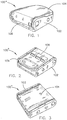
- FIGS. 1 through 7 illustrate example embodiments of a safety belt buckle 100 in accordance with various implementations.
- the safety belt buckle 100 includes a base member 102 and a release member 104 coupled to the base member.
- the release member 104 is configured to release a tongue held between the release member and the base member 102 when the release member 104 is pulled away from the base member 102.
- a safety belt includes two strap portions that wrap around a passenger to secure the passenger to a seat or any other passenger support structure.
- the safety belt has a tongue coupled to an end of a first strap portion and a safety belt buckle 100 coupled to an end of a second strap portion.
- the tongue is configured to mate with the safety belt buckle 100.
- the safety belt buckle 100 can include a slot 106 disposed at a front portion of the safety belt buckle 100 and configured to receive the tongue. The tongue is then held in between the base member 102 and the release member 104 until the passenger lifts or pulls the release member 104 away from the base member 102 to unlatch the tongue from the safety belt buckle 100.
- the safety belt buckle 100a can be manufactured to have various design features and/or according to different form factors.
- FIG. 1 illustrates an example embodiment of the safety belt buckle 100 with a simple design.
- FIG. 2 illustrates an example embodiment of the safety belt buckle 100b with a more complex design that includes a 3D pattern 108 of parallelograms formed on a top surface of the release member 104.
- the safety belt buckle 100 can also include other indentations or protuberances formed on the release member 104 and/or the base member 102.
- the safety belt buckle 100 may also include paint or other colored material (e.g., colored plastic, rubber, or metal) formed on the top surface, upon protuberances on the top surface, and/or within indentations formed in the top surface of the release member 104.
- FIGS. 4 and 5 also illustrate example embodiments of the safety belt buckle 100d, 100e with 3D patterns 108 on the top surface of the release member 104.
- the 3D pattern 108 on a release member 104 (and/or a base member 102) includes a repeating pattern of geometric shapes.
- the 3D pattern 108 in FIG.4 includes repeating diamonds
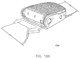
- the 3D pattern in FIG. 5 includes repeating chevrons.
- FIG. 3 illustrates another example embodiment of the safety belt buckle 100c with a complex design that includes raised edges on the release member 104 for a more distinctive appearance.
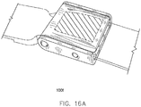
- FIG. 6 illustrates an example embodiment of the safety belt buckle 100f with a design similar to the safety belt buckle 100 illustrated in FIG. 3 , where the release member 104 includes a recess 110 with an in-mold feature 112 disposed (e.g., embedded) within the recess 110.
- the in-mold feature 112 can be injection molded with the release member 104 structure and/or the release member 104 structure can be cast around the in-mold feature 112. It is noted that while an in-mold feature 112 is shown in combination with the safety belt buckle 100c structure of FIG.
- any other safety belt buckle 100 can include an in-mold feature 112.
- the in-mold feature 112 includes a pattern (e.g., a geometric pattern) or design.
- the in-mold feature 112 can additionally or alternatively include a brand name, a logo, and/or a message.
- the in-mold feature 112 includes an informational message (e.g., a safety message or warning).
- the in-mold feature 112 includes a promotional message (e.g., an advertisement).
- the in-mold feature 112 can include an advertisement paid for by a commercial entity wishing to advertise products or services on an aircraft or other vehicle (e.g., bus, train, etc.) that includes the safety belt buckles 100.
- an in-mold labeling (IML) or in-mold decorating (IMD) process can be used to add an in-mold feature 112 comprising a thin sheet/film embedded within the top surface of the release member 104 (e.g., where the release member 104 may be an injection molded structure).
- the sheet/film may have ink applied to the sheet/film.
- the ink can be printed in the form of a pattern, grain, wording, miscellaneous branding, etc. This ink could be a single color or multicolor.
- the ink could also be applied to either side of the sheet/film.
- the sheet/film could range in thickness and texture type (including soft touch). Techniques other than IML/IMD can be implemented to achieve desired effects. This can include, but is not limited to, metallic pigments in the material, in mold painting, hydro dipping, electroplating, vacuum metalization, thermo/pressure forming, etc.
- the in-mold feature 112 includes a film, sheet, or injection molded chip of plastic can be integrated into a designated area of the release member 104.
- This film, sheet, or injection molded chip can be held in with adhesive, mechanically, magnetically, or by other similar means.
- the film, sheet, or injection molded chip may have the option to be permanent or removable (e.g., interchangeable).
- ink is printed on a sheet/film (potentially with a distorted image to compensate for the stretching/warping during the forming process).
- the sheet/film is thermoformed, pressure formed, or formed by any other forming technology to create the shape of the part.
- the sheet/film can be trimmed down to the desired shape of the part.
- Static electricity, mechanical fixtures, or other tools or devices are used to hold the sheet/film into an injection mold. Molten plastic is then flown into the mold behind the sheet/film, filling the cavity and causing the sheet/film and injection molding material to become one complete item (e.g., the release member 104 with the in-mold feature 112 embedded therein).
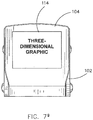
- FIG. 7 illustrates an example embodiment of the safety belt buckle 100g with the release member 104 including a 3D graphic 114 printed on a top surface of the release member 104.
- the 3D graphic 114 may be formed by one or more printed device layers of a plurality of printed device layers that form the release member 104 and/or the base member 102 of the safety belt buckle 100.
- the 3D graphic 114 includes a 3D pattern (e.g., a geometric pattern) or design.
- the 3D graphic 114 can additionally or alternatively include a brand name, a logo, and/or a message.
- the 3D graphic 114 includes an informational message (e.g., a safety message or warning).
- the 3D graphic 114 includes a promotional message (e.g., an advertisement).
- the 3D graphic 114 can include an advertisement paid for by a commercial entity wishing to advertise products or services on an aircraft or other vehicle (e.g., bus, train, etc.) that includes the safety belt buckles 100.
- the 3D graphic 114 has paint or other colored material (e.g., colored plastic, rubber, or metal) disposed upon and/or forming a portion of the 3D graphic 114.
- FIG. 8 illustrates a cross-sectional view of the release member 104 of the safety belt buckle 100 in accordance with an example embodiment of the current invention.
- the release member 104 is formed by a plurality of printed device layers 116 (e.g., printed metal and/or plastic device layers).
- the printed device layers 116 are metal device layers formed on top of one another using a 3D printer or other type of additive manufacturing device.
- One or more of the printed device layers 116 can form a 3D pattern 108 on a top surface of the release member 104.
- a colored layer 118 e.g., a paint layer, other colored material, and/or another (colored) printed device layer
- FIG. 9 illustrates a cross-sectional view of the release member 104 of the safety belt buckle 100 in accordance with another example embodiment of the current invention.
- the release member 104 can be formed by a plurality of printed device layers 120 (e.g., printed metal and/or plastic device layers).
- a surface coating 122 e.g., metallic coating, plastic coating, rubberized coating, or the like
- the printed device layers 120 are plastic device layers formed on top of one another using a 3D printer or other type of additive manufacturing device, and the surface coating 122 is a metal coating disposed upon the plurality of printed device layers 120.
- One or more of the printed device layers 120 can form a 3D pattern 108 on a top surface of the release member 104.
- a colored layer 118 e.g., a paint layer, other colored material, and/or another (colored) printed device layer
- FIG. 10 illustrates a cross-sectional view of the release member 104 of the safety belt buckle 100 in accordance with another example embodiment of the current invention.
- the release member 104 is formed by a plurality of printed device layers 116 (e.g., printed metal and/or plastic device layers).
- the printed device layers 116 are metal device layers formed on top of one another using a 3D printer or other type of additive manufacturing device.
- One or more of the printed device layers 116 can form a 3D graphic 114 on a top surface of the release member 104.
- a colored layer 118 e.g., a paint layer, other colored material, and/or another (colored) printed device layer
- FIG. 11 illustrates a cross-sectional view of the release member 104 of the safety belt buckle 100 in accordance with another example embodiment of the current invention.
- the release member 104 can be formed by a plurality of printed device layers 120 (e.g., printed metal and/or plastic device layers).
- a surface coating 122 e.g., metallic coating, plastic coating, rubberized coating, or the like
- the printed device layers 120 are plastic device layers formed on top of one another using a 3D printer or other type of additive manufacturing device, and the surface coating 122 is a metal coating disposed upon the plurality of printed device layers 120.
- One or more of the printed device layers 120 can form a 3D graphic 114 on a top surface of the release member 104.
- a colored layer 118 e.g., a paint layer, other colored material, and/or another (colored) printed device layer
- FIGS. 12A through 12C illustrate an example embodiment of a 3D printer 200 forming a plurality of printed device layers (e.g., printed device layers 116 or 120) to manufacture a safety belt buckle 100 or at least a portion thereof (e.g., the base member 102 and/or the release member 104).
- the 3D printer 200 includes one or more feeders configured to feed one or more strands of device material (e.g., metal and/or plastic 3D print filament) to a print nozzle 202 (or an assembly of print nozzles).
- the 3D printer 200 may further include a stage 206 configured to support printed device layers and an arm 204 configured to hold the print nozzle 202 above the stage 206.
- the stage 206 and/or the arm 204 can be configured to actuate (e.g., up, down, forwards, backwards, and/or sideways) so that the printed device layers can be disposed upon one another to form a 3D printed structure (e.g., base member 102 and/or release member 104).
- the 3D printer 200 illustrated in FIGS. 12A through 12C is provided as an example, and it is to be understood that other types of 3D printers can be employed.
- the base member 102 and/or release member 104 structures may be formed from any 3D printing material or combination of materials that meet structural specifications for the safety belt buckle 100 structures described herein.
- 3D printing materials include, but are not limited to: Polylactic Acid (PLA) printing filament; Acrylonitrile Butadiene Styrene (ABS) printing filament; PRO Series PLA printing filament; PRO Series ABS printing filament; Polyamide (aka Nylon) printing filament; Polyamide With Chopped Carbon Fiber Strands (aka NylonX) printing filament; PRO Series Nylon printing filament; Polyethylene terephthalate (PET) printing filament; PETG printing filament; PETT printing filament; PRO Series PET, PETG, or PETT printing filament; Acrylonitrile Styrene Acrylate (ASA) printing filament; PolyPropylene (PP) printing filament; and combinations thereof.
- any combination of the foregoing device materials may be included in example embodiments of the safety belt buckle 100 described herein.
- the foregoing list of device materials is not exhaustive, and it is contemplated that other device materials with similar structural properties and/or metals can be used in combination with or in place of the listed device materials.
- the safety belt buckle 100 or at least a portion thereof is plated or otherwise covered by a surface coating 122 (e.g., a metal coating).
- a surface coating 122 e.g., a metal coating
- FIGS. 9 and 11 illustrate example embodiments of the safety belt buckle 100 with a surface coating 122 disposed upon the printed layers 120 that form the release member 104.
- the surface coating 122 is applied by a coating system 300 that includes a conveyer 302 configured to transport the safety belt buckle 100 or at least a portion thereof (e.g., base member 102 and/or release member 104) to a container 304 with surface coating material 122 (e.g., electroplating solution) disposed therein.
- the safety belt buckle 100 structure (e.g., base member 102 and/or release member 104) can then be submerged within the surface coating material 122 to cover the safety belt buckle 100 structure (e.g., base member 102 and/or release member 104) with the surface coating 122.
- the surface coating material 122 can be poured onto or otherwise deposited onto the surface of the safety belt buckle 100 structure (e.g., base member 102 and/or release member 104).
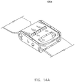
- FIGS. 14A through 19G illustrate additional views of some of the example embodiments of the safety belt buckle 100 described herein.
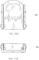
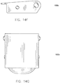
- FIGS. 14A through 14G illustrate additional views of the example embodiment of the safety belt buckle 100b illustrated in FIG. 2 ;
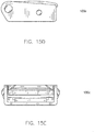
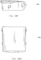
- FIGS. 15A through 15G illustrate additional views of the example embodiment of the safety belt buckle 100c illustrated in FIG. 3 ;
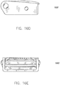
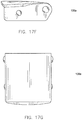
- FIGS. 16A through 16G illustrate additional views of the example embodiment of the safety belt buckle 100f illustrated in FIG. 6 ;
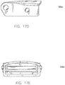
- FIGS. 17A through 17G illustrate additional views of the example embodiment of the safety belt buckle 100a illustrated in FIG. 1 ;
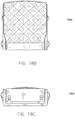
- FIGS. 18A through 18G illustrate additional views of the example embodiment of the safety belt buckle 100d illustrated in FIG. 4 ;
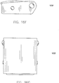
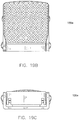
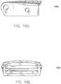
- FIGS. 19A through 19G illustrate additional views of the example embodiment of the safety belt buckle 100e illustrated in FIG. 5 .
- embodiments of the methods according to the inventive concepts disclosed herein may include one or more of the steps described herein. Further, such steps may be carried out in any desired order and two or more of the steps may be carried out simultaneously with one another. Two or more of the steps disclosed herein may be combined in a single step, and in some embodiments, one or more of the steps may be carried out as two or more sub-steps. Further, other steps or sub-steps may be carried in addition to, or as substitutes to one or more of the steps disclosed herein.
Landscapes
- Automotive Seat Belt Assembly (AREA)
Abstract
Description
- Vehicles for mass transport can include, but are not limited to, aircrafts, boats, trains, and busses. The passenger cabins in these types of vehicles are typically designed for long travel durations (e.g., one or more hours of travel). Turbulence or hazards may be encountered during travel, and as such, passengers are encouraged to wear safety belts (e.g., seat belts) at all times when the passengers are not moving throughout the cabin (e.g., to use the restroom, to retrieve an item, etc.).
- The structure and visual appearance of safety belt buckles can be important. For example, it may be desirable to provide different safety belt buckles for first class or business class cabins than those provided for economy cabins. It can also be desirable to provide customized safety belt buckles. Current techniques for manufacturing safety belt buckles, such as metal casting, are not well-suited for manufacturing small batches. Thus, customized safety belt buckles may have a high expense. There is a need for improved techniques for manufacturing safety belt buckles, particularly customized safety belt buckles.
- In one aspect, the inventive concepts disclosed herein are directed to passenger safety belt buckle structures and techniques for manufacturing the same. According to the instant invention, a safety belt buckle includes a base member and a release member coupled to the base member. Typically, a tongue can be releasably held between the release member and the base member, to maintain two parts of the safety belt in an engaged use position The release member is configured to release the tongue held between the release member and the base member when the release member is pulled away from the base member. According to one aspect of the invention, the release member is formed by a plurality of printed device layers and a metal coating disposed over the plurality of printed device layers. According to another aspect of the invention the release member is formed by a plurality of printed metal layers. According to yet another aspect of the current invention, the release member includes a recess with an in-mold feature disposed within the recess.
The safety belt buckles according to the current invention are manufactured in a way that they can be produced in small batches more efficiently then the known safety buckles, because their manufacturing does not, like with metal casting, require relatively expensive molds. - This summary is provided solely as an introduction to subject matter that is fully described in the detailed description and drawings. The summary should not be considered to describe essential features nor be used to determine the scope of the invention which is defined by the claims. Moreover, it is to be understood that both the foregoing summary and the following detailed description are example and explanatory only and are not necessarily restrictive of the subject matter claimed.
- Implementations of the inventive concepts disclosed herein may be better understood when consideration is given to the following detailed description thereof. Such description makes reference to the included drawings, which are not necessarily to scale, and in which some features may be exaggerated and some features may be omitted or may be represented schematically in the interest of clarity. Like reference numerals in the drawings may represent and refer to the same or similar element, feature, or function. In the drawings:
-
FIG. 1 is a perspective view of a safety belt buckle, in accordance with the current invention; -
FIG. 2 is a perspective view of a safety belt buckle, in accordance with the current invention; -
FIG. 3 is a perspective view of a safety belt buckle, in accordance with the current invention; -
FIG. 4 is a perspective view of a safety belt buckle, in accordance with the current invention; -
FIG. 5 is a perspective view of a safety belt buckle, in accordance with the current invention; -
FIG. 6 is a perspective view of a safety belt buckle, in accordance with the current invention; -
FIG. 7 is a top view of a safety belt buckle, in accordance with the current invention; -
FIG. 8 is a partial cross-sectional view of a release member of a safety belt buckle, in accordance with the current invention; -
FIG. 9 is a partial cross-sectional view of a release member of a safety belt buckle, in accordance with the current invention; -
FIG. 10 is a partial cross-sectional view of a release member of a safety belt buckle, in accordance with the current invention; -
FIG. 11 is a partial cross-sectional view of a release member of a safety belt buckle, in accordance with the current invention; -
FIG. 12A is an illustration of a three-dimensional printer for manufacturing a safety belt buckle or a portion thereof, in accordance with the current invention; -
FIG. 12B is an illustration of a three-dimensional printer for manufacturing a safety belt buckle or a portion thereof, in accordance with the current invention; -
FIG. 12C is an illustration of a three-dimensional printer for manufacturing a safety belt buckle or a portion thereof, in accordance with the current invention e; -
FIG. 13 is an illustration of a system for applying a surface coating to a safety belt buckle or a portion thereof, in accordance with the current invention; -
FIG. 14A is a perspective view of a safety belt buckle, in accordance with the current invention; -
FIG. 14B is a top plan view of the safety belt buckle ofFIG. 14A ; -
FIG. 14C is a front elevation view of the safety belt buckle ofFIG. 14A ; -
FIG. 14D is a left side elevation view of the safety belt buckle ofFIG. 14A ; -
FIG. 14E is a rear elevation view of the safety belt buckle ofFIG. 14A ; -
FIG. 14F is a right side elevation view of the safety belt buckle ofFIG. 14A -
FIG. 14G is a bottom plan view of the safety belt buckle ofFIG. 14A ; -
FIG. 15A is a perspective view of a safety belt buckle, in accordance with the current invention; -
FIG. 15B is a top plan view of the safety belt buckle ofFIG. 15A ; -
FIG. 15C is a front elevation view of the safety belt buckle ofFIG. 15A ; -
FIG. 15D is a left side elevation view of the safety belt buckle ofFIG. 15A ; -
FIG. 15E is a rear elevation view of the safety belt buckle ofFIG. 15A ; -
FIG. 15F is a right side elevation view of the safety belt buckle ofFIG. 15A ; -
FIG. 15G is a bottom plan view of the safety belt buckle ofFIG. 15A ; -
FIG. 16A is a perspective view of a safety belt buckle, in accordance with the current invention e; -
FIG. 16B is a top plan view of the safety belt buckle ofFIG. 16A ; -
FIG. 16C is a front elevation view of the safety belt buckle ofFIG. 16A ; -
FIG. 16D is a left side elevation view of the safety belt buckle ofFIG. 16A ; -
FIG. 16E is a rear elevation view of the safety belt buckle ofFIG. 16A ; -
FIG. 16F is a right side elevation view of the safety belt buckle ofFIG. 16A ; -
FIG. 16G is a bottom plan view of the safety belt buckle ofFIG. 16A ; -
FIG. 17A is a perspective view of a safety belt buckle, in accordance the current invention; -
FIG. 17B is a top plan view of the safety belt buckle ofFIG. 17A ; -
FIG. 17C is a front elevation view of the safety belt buckle ofFIG. 17A ; -
FIG. 17D is a left side elevation view of the safety belt buckle ofFIG. 17A ; -
FIG. 17E is a rear elevation view of the safety belt buckle ofFIG. 17A ; -
FIG. 17F is a right side elevation view of the safety belt buckle ofFIG. 17A ; -
FIG. 17G is a bottom plan view of the safety belt buckle ofFIG. 17A ; -
FIG. 18A is a perspective view of a safety belt buckle, in accordance with the current invention e; -
FIG. 18B is a top plan view of the safety belt buckle ofFIG. 18A ; -
FIG. 18C is a front elevation view of the safety belt buckle ofFIG. 18A ; -
FIG. 18D is a left side elevation view of the safety belt buckle ofFIG. 18A ; -
FIG. 18E is a rear elevation view of the safety belt buckle ofFIG. 18A ; -
FIG. 18F is a right side elevation view of the safety belt buckle ofFIG. 18A ; -
FIG. 18G is a bottom plan view of the safety belt buckle ofFIG. 18A ; -
FIG. 19A is a perspective view of a safety belt buckle, in accordance with the current invention; -
FIG. 19B is a top plan view of the safety belt buckle ofFIG. 19A ; -
FIG. 19C is a front elevation view of the safety belt buckle ofFIG. 19A ; -
FIG. 19D is a left side elevation view of the safety belt buckle ofFIG. 19A ; -
FIG. 19E is a rear elevation view of the safety belt buckle ofFIG. 19A ; -
FIG. 19F is a right side elevation view of the safety belt buckle ofFIG. 19A ; and -
FIG. 19G is a bottom plan view of the safety belt buckle ofFIG. 19A . - Before explaining at least one embodiment of the inventive concepts disclosed herein in detail, it is to be understood that the inventive concepts limited by the appended laimes, and are not limited any further in their application to the details of construction and the arrangement of the components or steps or methodologies set forth in the following description or illustrated in the drawings. In the following detailed description of embodiments of the instant inventive concepts, numerous specific details are set forth in order to provide a more thorough understanding of the inventive concepts. However, it will be apparent to one of ordinary skill in the art having the benefit of the instant disclosure that the inventive concepts disclosed herein may be practiced without these specific details. In other instances, well-known features may not be described in detail to avoid unnecessarily complicating the instant disclosure. The inventive concepts disclosed herein are capable of other embodiments or of being practiced or carried out in various ways. Also, it is to be understood that the phraseology and terminology employed herein is for the purpose of description and should not be regarded as limiting.
- As used herein a letter following a reference numeral is intended to reference an embodiment of the feature or element that may be similar, but not necessarily identical, to a previously described element or feature bearing the same reference numeral (e.g., 1, 1a, 1b). Such shorthand notations are used for purposes of convenience only, and should not be construed to limit the inventive concepts disclosed herein in any way unless expressly stated to the contrary.
- Further, unless expressly stated to the contrary, "or" refers to an inclusive or and not to an exclusive or. For example, a condition A or B is satisfied by anyone of the following: A is true (or present) and B is false (or not present), A is false (or not present) and B is true (or present), and both A and B are true (or present).
- In addition, use of the "a" or "an" are employed to describe elements and components of embodiments of the instant inventive concepts. This is done merely for convenience and to give a general sense of the inventive concepts, and "a' and "an" are intended to include one or at least one and the singular also includes the plural unless it is obvious that it is meant otherwise.
- Finally, as used herein any reference to "one embodiment," or "some embodiments" means that a particular element, feature, structure, or characteristic described in connection with the embodiment is included in at least one embodiment of the inventive concepts disclosed herein. The appearances of the phrase "in some embodiments" in various places in the specification are not necessarily all referring to the same embodiment, and embodiments of the inventive concepts disclosed may include one or more of the features expressly described or inherently present herein, or any combination of sub-combination of two or more such features, along with any other features which may not necessarily be expressly described or inherently present in the instant disclosure.
- Broadly, embodiments of the inventive concepts disclosed herein are directed to passenger safety belt buckle structures and techniques for manufacturing the same. Traditional approaches for manufacturing safety belt buckle structures, such as metal casting, have worked well for various applications, but improvements in additive manufacturing (e.g., three-dimensional (3D) printing) and injection molding technology have opened up new possibilities for creating safety belt buckle structures, particularly customized safety belt buckle structures. In example embodiments of the current invention, a safety belt buckle release member and/or base member may be formed by a plurality of printed device layers (e.g., printed metal and/or plastic device layers). For example, the release member can be formed by a plurality of printed device layers and a metal coating disposed over the plurality of printed device layers and/or by a plurality of printed metal layers. In this manner, the release member can be designed to include a 3D pattern and/or a 3D graphic (e.g., brand name, logo, advertisement, or any other symbol or text) on a top surface of the release member. In another example embodiment, the release member can include a recess with an in-mold feature disposed within the recess. For example, the release member can have an in-mold feature that includes a pattern, logo, image, text, or the like, embedded within a top surface of the release member.
-
FIGS. 1 through 7 illustrate example embodiments of asafety belt buckle 100 in accordance with various implementations. Thesafety belt buckle 100 includes abase member 102 and arelease member 104 coupled to the base member. Therelease member 104 is configured to release a tongue held between the release member and thebase member 102 when therelease member 104 is pulled away from thebase member 102. For example, a safety belt includes two strap portions that wrap around a passenger to secure the passenger to a seat or any other passenger support structure. The safety belt has a tongue coupled to an end of a first strap portion and asafety belt buckle 100 coupled to an end of a second strap portion. The tongue is configured to mate with thesafety belt buckle 100. For example, thesafety belt buckle 100 can include aslot 106 disposed at a front portion of thesafety belt buckle 100 and configured to receive the tongue. The tongue is then held in between thebase member 102 and therelease member 104 until the passenger lifts or pulls therelease member 104 away from thebase member 102 to unlatch the tongue from thesafety belt buckle 100. - As shown in
FIGS. 1 through 7 , thesafety belt buckle 100a can be manufactured to have various design features and/or according to different form factors. For example,FIG. 1 illustrates an example embodiment of thesafety belt buckle 100 with a simple design.FIG. 2 illustrates an example embodiment of thesafety belt buckle 100b with a more complex design that includes a3D pattern 108 of parallelograms formed on a top surface of therelease member 104. Thesafety belt buckle 100 can also include other indentations or protuberances formed on therelease member 104 and/or thebase member 102. Thesafety belt buckle 100 may also include paint or other colored material (e.g., colored plastic, rubber, or metal) formed on the top surface, upon protuberances on the top surface, and/or within indentations formed in the top surface of therelease member 104.FIGS. 4 and 5 also illustrate example embodiments of thesafety belt buckle 3D patterns 108 on the top surface of therelease member 104. In some embodiments, the3D pattern 108 on a release member 104 (and/or a base member 102) includes a repeating pattern of geometric shapes. For example, the3D pattern 108 inFIG.4 includes repeating diamonds, and the 3D pattern inFIG. 5 includes repeating chevrons. -
FIG. 3 illustrates another example embodiment of thesafety belt buckle 100c with a complex design that includes raised edges on therelease member 104 for a more distinctive appearance.FIG. 6 illustrates an example embodiment of thesafety belt buckle 100f with a design similar to thesafety belt buckle 100 illustrated inFIG. 3 , where therelease member 104 includes arecess 110 with an in-mold feature 112 disposed (e.g., embedded) within therecess 110. For example, the in-mold feature 112 can be injection molded with therelease member 104 structure and/or therelease member 104 structure can be cast around the in-mold feature 112. It is noted that while an in-mold feature 112 is shown in combination with thesafety belt buckle 100c structure ofFIG. 3 , any other safety belt buckle 100 (e.g., as shown inFIGS. 1, 2, 3 , or4 ) can include an in-mold feature 112. In some embodiments, the in-mold feature 112 includes a pattern (e.g., a geometric pattern) or design. The in-mold feature 112 can additionally or alternatively include a brand name, a logo, and/or a message. In some embodiments, the in-mold feature 112 includes an informational message (e.g., a safety message or warning). In other embodiments, the in-mold feature 112 includes a promotional message (e.g., an advertisement). For example, the in-mold feature 112 can include an advertisement paid for by a commercial entity wishing to advertise products or services on an aircraft or other vehicle (e.g., bus, train, etc.) that includes the safety belt buckles 100. - In some implementations, an in-mold labeling (IML) or in-mold decorating (IMD) process can be used to add an in-
mold feature 112 comprising a thin sheet/film embedded within the top surface of the release member 104 (e.g., where therelease member 104 may be an injection molded structure). The sheet/film may have ink applied to the sheet/film. For example, the ink can be printed in the form of a pattern, grain, wording, miscellaneous branding, etc. This ink could be a single color or multicolor. The ink could also be applied to either side of the sheet/film. The sheet/film could range in thickness and texture type (including soft touch). Techniques other than IML/IMD can be implemented to achieve desired effects. This can include, but is not limited to, metallic pigments in the material, in mold painting, hydro dipping, electroplating, vacuum metalization, thermo/pressure forming, etc. - In other implementations, the in-
mold feature 112 includes a film, sheet, or injection molded chip of plastic can be integrated into a designated area of therelease member 104. This film, sheet, or injection molded chip can be held in with adhesive, mechanically, magnetically, or by other similar means. The film, sheet, or injection molded chip may have the option to be permanent or removable (e.g., interchangeable). - Various techniques can be used to embed an in-
mold feature 112 within therelease member 104 structure. For example, in some implementations, ink is printed on a sheet/film (potentially with a distorted image to compensate for the stretching/warping during the forming process). The sheet/film is thermoformed, pressure formed, or formed by any other forming technology to create the shape of the part. The sheet/film can be trimmed down to the desired shape of the part. Static electricity, mechanical fixtures, or other tools or devices are used to hold the sheet/film into an injection mold. Molten plastic is then flown into the mold behind the sheet/film, filling the cavity and causing the sheet/film and injection molding material to become one complete item (e.g., therelease member 104 with the in-mold feature 112 embedded therein). -
FIG. 7 illustrates an example embodiment of the safety belt buckle 100g with therelease member 104 including a 3D graphic 114 printed on a top surface of therelease member 104. For example, the 3D graphic 114 may be formed by one or more printed device layers of a plurality of printed device layers that form therelease member 104 and/or thebase member 102 of thesafety belt buckle 100. In some embodiments, the3D graphic 114 includes a 3D pattern (e.g., a geometric pattern) or design. The 3D graphic 114 can additionally or alternatively include a brand name, a logo, and/or a message. In some embodiments, the3D graphic 114 includes an informational message (e.g., a safety message or warning). In other embodiments, the3D graphic 114 includes a promotional message (e.g., an advertisement). For example, the 3D graphic 114 can include an advertisement paid for by a commercial entity wishing to advertise products or services on an aircraft or other vehicle (e.g., bus, train, etc.) that includes the safety belt buckles 100. In some embodiments, the3D graphic 114 has paint or other colored material (e.g., colored plastic, rubber, or metal) disposed upon and/or forming a portion of the3D graphic 114. -
FIG. 8 illustrates a cross-sectional view of therelease member 104 of thesafety belt buckle 100 in accordance with an example embodiment of the current invention. Therelease member 104 is formed by a plurality of printed device layers 116 (e.g., printed metal and/or plastic device layers). In an example embodiment, the printed device layers 116 are metal device layers formed on top of one another using a 3D printer or other type of additive manufacturing device. One or more of the printed device layers 116 can form a3D pattern 108 on a top surface of therelease member 104. In some embodiments, a colored layer 118 (e.g., a paint layer, other colored material, and/or another (colored) printed device layer) is disposed upon the3D pattern 108 to form colored portions of the3D pattern 108. -
FIG. 9 illustrates a cross-sectional view of therelease member 104 of thesafety belt buckle 100 in accordance with another example embodiment of the current invention. Therelease member 104 can be formed by a plurality of printed device layers 120 (e.g., printed metal and/or plastic device layers). A surface coating 122 (e.g., metallic coating, plastic coating, rubberized coating, or the like) can then be applied over the plurality of printed device layers 120. In an example embodiment, the printed device layers 120 are plastic device layers formed on top of one another using a 3D printer or other type of additive manufacturing device, and thesurface coating 122 is a metal coating disposed upon the plurality of printed device layers 120. One or more of the printed device layers 120 can form a3D pattern 108 on a top surface of therelease member 104. In some embodiments, a colored layer 118 (e.g., a paint layer, other colored material, and/or another (colored) printed device layer) is disposed upon the3D pattern 108 to form colored portions of the3D pattern 108. -
FIG. 10 illustrates a cross-sectional view of therelease member 104 of thesafety belt buckle 100 in accordance with another example embodiment of the current invention. Therelease member 104 is formed by a plurality of printed device layers 116 (e.g., printed metal and/or plastic device layers). In an example embodiment, the printed device layers 116 are metal device layers formed on top of one another using a 3D printer or other type of additive manufacturing device. One or more of the printed device layers 116 can form a 3D graphic 114 on a top surface of therelease member 104. In some embodiments, a colored layer 118 (e.g., a paint layer, other colored material, and/or another (colored) printed device layer) is disposed upon the 3D graphic 114 to form colored portions of the3D graphic 114. -
FIG. 11 illustrates a cross-sectional view of therelease member 104 of thesafety belt buckle 100 in accordance with another example embodiment of the current invention. Therelease member 104 can be formed by a plurality of printed device layers 120 (e.g., printed metal and/or plastic device layers). A surface coating 122 (e.g., metallic coating, plastic coating, rubberized coating, or the like) can then be applied over the plurality of printed device layers 120. In an example embodiment, the printed device layers 120 are plastic device layers formed on top of one another using a 3D printer or other type of additive manufacturing device, and thesurface coating 122 is a metal coating disposed upon the plurality of printed device layers 120. One or more of the printed device layers 120 can form a 3D graphic 114 on a top surface of therelease member 104. In some embodiments, a colored layer 118 (e.g., a paint layer, other colored material, and/or another (colored) printed device layer) is disposed upon the 3D graphic 114 to form colored portions of the3D graphic 114. -
FIGS. 12A through 12C illustrate an example embodiment of a3D printer 200 forming a plurality of printed device layers (e.g., printed device layers 116 or 120) to manufacture asafety belt buckle 100 or at least a portion thereof (e.g., thebase member 102 and/or the release member 104). In embodiments, the3D printer 200 includes one or more feeders configured to feed one or more strands of device material (e.g., metal and/or plastic 3D print filament) to a print nozzle 202 (or an assembly of print nozzles). The3D printer 200 may further include astage 206 configured to support printed device layers and anarm 204 configured to hold theprint nozzle 202 above thestage 206. Thestage 206 and/or thearm 204 can be configured to actuate (e.g., up, down, forwards, backwards, and/or sideways) so that the printed device layers can be disposed upon one another to form a 3D printed structure (e.g.,base member 102 and/or release member 104). The3D printer 200 illustrated inFIGS. 12A through 12C is provided as an example, and it is to be understood that other types of 3D printers can be employed. - In embodiments, the
base member 102 and/orrelease member 104 structures (e.g., printed device layers 116 or 120) may be formed from any 3D printing material or combination of materials that meet structural specifications for thesafety belt buckle 100 structures described herein. Some examples of 3D printing materials include, but are not limited to: Polylactic Acid (PLA) printing filament; Acrylonitrile Butadiene Styrene (ABS) printing filament; PRO Series PLA printing filament; PRO Series ABS printing filament; Polyamide (aka Nylon) printing filament; Polyamide With Chopped Carbon Fiber Strands (aka NylonX) printing filament; PRO Series Nylon printing filament; Polyethylene terephthalate (PET) printing filament; PETG printing filament; PETT printing filament; PRO Series PET, PETG, or PETT printing filament; Acrylonitrile Styrene Acrylate (ASA) printing filament; PolyPropylene (PP) printing filament; and combinations thereof. Any combination of the foregoing device materials may be included in example embodiments of thesafety belt buckle 100 described herein. However, the foregoing list of device materials is not exhaustive, and it is contemplated that other device materials with similar structural properties and/or metals can be used in combination with or in place of the listed device materials. - In some embodiments, the
safety belt buckle 100 or at least a portion thereof (e.g.,base member 102 and/or release member 104) is plated or otherwise covered by a surface coating 122 (e.g., a metal coating). For example,FIGS. 9 and11 illustrate example embodiments of thesafety belt buckle 100 with asurface coating 122 disposed upon the printedlayers 120 that form therelease member 104. In an example implementation, thesurface coating 122 is applied by acoating system 300 that includes aconveyer 302 configured to transport thesafety belt buckle 100 or at least a portion thereof (e.g.,base member 102 and/or release member 104) to acontainer 304 with surface coating material 122 (e.g., electroplating solution) disposed therein. Thesafety belt buckle 100 structure (e.g.,base member 102 and/or release member 104) can then be submerged within thesurface coating material 122 to cover thesafety belt buckle 100 structure (e.g.,base member 102 and/or release member 104) with thesurface coating 122. In other implementations, thesurface coating material 122 can be poured onto or otherwise deposited onto the surface of thesafety belt buckle 100 structure (e.g.,base member 102 and/or release member 104). -
FIGS. 14A through 19G illustrate additional views of some of the example embodiments of thesafety belt buckle 100 described herein. For example,FIGS. 14A through 14G illustrate additional views of the example embodiment of thesafety belt buckle 100b illustrated inFIG. 2 ;FIGS. 15A through 15G illustrate additional views of the example embodiment of thesafety belt buckle 100c illustrated inFIG. 3 ;FIGS. 16A through 16G illustrate additional views of the example embodiment of thesafety belt buckle 100f illustrated inFIG. 6 ;FIGS. 17A through 17G illustrate additional views of the example embodiment of thesafety belt buckle 100a illustrated inFIG. 1 ;FIGS. 18A through 18G illustrate additional views of the example embodiment of thesafety belt buckle 100d illustrated inFIG. 4 ; andFIGS. 19A through 19G illustrate additional views of the example embodiment of thesafety belt buckle 100e illustrated inFIG. 5 . - It is to be understood that embodiments of the methods according to the inventive concepts disclosed herein may include one or more of the steps described herein. Further, such steps may be carried out in any desired order and two or more of the steps may be carried out simultaneously with one another. Two or more of the steps disclosed herein may be combined in a single step, and in some embodiments, one or more of the steps may be carried out as two or more sub-steps. Further, other steps or sub-steps may be carried in addition to, or as substitutes to one or more of the steps disclosed herein.
- From the above description, it is clear that the inventive concepts disclosed herein are well adapted to carry out the objects and to attain the advantages mentioned herein as well as those inherent in the inventive concepts disclosed herein. While presently preferred embodiments of the inventive concepts disclosed herein have been described for purposes of this disclosure, it will be understood that numerous changes may be made which will readily suggest themselves to those skilled in the art and which are accomplished within the broad scope and coverage of the appended claims.
Claims (11)
- A safety belt buckle (100), comprising:a base member (102); anda release member (104) coupled to the base member (102), the release member (104) configured to release a tongue held between the release member (104) and the base member (102) when the release member (104) is pulled away from the base member (102), the release member (104) comprising a plurality of printed device layers and a metal coating (122) disposed over the plurality of printed device layers (116, 120) and/or the release member (104) including a recess (110) with an in-mold feature disposed within the recess (110).
- The safety buckle according to claim 1, wherein the printed device layers comprise one or more printed metal layers.
- The safety buckle according to claim 1 or 2, wherein the printed device layers comprise one or more printed non-metalic layers.
- The safety belt buckle according to one or more of claims 1-3, wherein the plurality of printed device layers (116, 120) form a three-dimensional pattern (108) on the release member (104).
- The safety belt buckle according to claim 4, wherein the three-dimensional pattern includes a repeating pattern of geometric shapes.
- The safety belt buckle according to claim 4 or 5, further comprising a paint layer disposed upon the three-dimensional pattern.
- The safety belt buckle according to one or more of claims 1-6, wherein the plurality of printed device layers (116, 120) form a three-dimensional graphic (114) on the release member (104).
- The safety belt buckle according to claim 7, wherein the three-dimensional graphic includes at least one of a brand name or a logo.
- The safety belt buckle according to claim 7 or 8, wherein the three-dimensional graphic includes at least one of a promotional message or an informational message.
- The safety belt buckle according to one or more of claims 7-9, further comprising a paint layer disposed upon the three-dimensional graphic.
- The safety belt buckle according to one or more of claims claim 1-10, wherein the in-mold feature includes a pattern, a brand name, a logo, a promotional message and/or an informational message.
Applications Claiming Priority (1)
| Application Number | Priority Date | Filing Date | Title |
|---|---|---|---|
| US15/948,815 US10485305B2 (en) | 2018-04-09 | 2018-04-09 | Passenger safety belt buckles |
Publications (3)
| Publication Number | Publication Date |
|---|---|
| EP3552511A2 true EP3552511A2 (en) | 2019-10-16 |
| EP3552511A3 EP3552511A3 (en) | 2019-11-20 |
| EP3552511B1 EP3552511B1 (en) | 2021-06-02 |
Family
ID=66101926
Family Applications (1)
| Application Number | Title | Priority Date | Filing Date |
|---|---|---|---|
| EP19167541.2A Active EP3552511B1 (en) | 2018-04-09 | 2019-04-05 | Method of manufacturing a safety belt buckle |
Country Status (3)
| Country | Link |
|---|---|
| US (1) | US10485305B2 (en) |
| EP (1) | EP3552511B1 (en) |
| CN (1) | CN110353364B (en) |
Families Citing this family (3)
| Publication number | Priority date | Publication date | Assignee | Title |
|---|---|---|---|---|
| USD853277S1 (en) * | 2018-04-06 | 2019-07-09 | Rockwell Collins, Inc. | Passenger safety belt buckle |
| USD1106873S1 (en) * | 2024-08-06 | 2025-12-23 | Joshua Landry | Buckle |
| USD1106874S1 (en) * | 2023-12-27 | 2025-12-23 | Joshua Landry | Buckle |
Family Cites Families (27)
| Publication number | Priority date | Publication date | Assignee | Title |
|---|---|---|---|---|
| SE360017B (en) * | 1971-04-13 | 1973-09-17 | Holmberg Gote Eskil Yngve | |
| DE2341601A1 (en) * | 1973-08-17 | 1975-02-27 | Artur Foehl | Light-weight safety belt clasp - is operated by one hand with tongue guided into locking box |
| GB1550182A (en) * | 1976-04-13 | 1979-08-08 | Kangol Magnet Ltd | Seat belt systems |
| DE2741297A1 (en) * | 1977-09-14 | 1979-03-22 | Lothar Depmeyer | Motor vehicle seat belt construction - has one anchor point fitted with strap slide-blocking and delaying eyelet fitting with wavy edge |
| DE3000969A1 (en) * | 1979-01-17 | 1980-08-07 | Kangol Magnet Ltd | BELT BUCKLE FOR MOTOR VEHICLE SEAT BELT |
| US4502188A (en) * | 1983-04-05 | 1985-03-05 | Buxton, Inc. | Theme belt buckle |
| DD217704A1 (en) * | 1983-09-01 | 1985-01-23 | Doebelner Beschlaege Metall | CLOSURE FOR SAFETY BELTS |
| US4766654A (en) * | 1984-10-19 | 1988-08-30 | Katsuyama Kinzoku Kogyo Kabushiki Kaisha | Push button buckle assembly for a seat belt |
| ES8706315A1 (en) * | 1986-03-25 | 1987-06-16 | Arnau Fernandez Mayoralas Joaq | Safety belt arrangement |
| IT218275Z2 (en) * | 1989-08-10 | 1992-04-14 | Vittorio Romano Barbuti | QUICK RELEASE DEVICE FOR SAFETY BELTS FOR CARS |
| US5765265A (en) * | 1997-06-05 | 1998-06-16 | Kang; Koo Seong | Belt buckle |
| US5926927A (en) * | 1997-12-13 | 1999-07-27 | Winkler; Marvin | Enhanced adjustable slider buckle means |
| US6237197B1 (en) * | 1999-04-28 | 2001-05-29 | Richard Cahill Donahue | Golf cart buckle lever retaining clip |
| US7566140B2 (en) * | 2005-09-09 | 2009-07-28 | Sevilla Ii Frederick J | Self illuminating belt buckle |
| US9480308B2 (en) * | 2007-10-12 | 2016-11-01 | Ford Global Technologies, Llc | Buckle-tongue arrangement for four point seat belt system |
| GB0905538D0 (en) | 2009-03-31 | 2009-05-13 | Cobra Uk Automotive Products D | Aircraft seat |
| US8763210B2 (en) * | 2010-01-15 | 2014-07-01 | Gv Snowshoes | Locking device for a buckle |
| WO2012117326A2 (en) * | 2011-02-28 | 2012-09-07 | Roland Iten | Mechanical lever buckle for belt and watch strap |
| US20120284972A1 (en) * | 2011-05-09 | 2012-11-15 | Hafdal Jane E | Belt Buckle Accessory |
| TW201343098A (en) * | 2012-04-23 | 2013-11-01 | yong-fa Su | Belt buckle structure |
| US20140259303A1 (en) * | 2013-03-15 | 2014-09-18 | Eric N. Eliason | Belt buckle with exchangable face plate |
| GB2524978A (en) | 2014-04-07 | 2015-10-14 | Wrasp Ltd | Buckle and seat belt comprising a buckle |
| CN104375695B (en) * | 2014-08-27 | 2017-10-17 | 合肥京东方显示光源有限公司 | Wearable display device, belt fastener and belt |
| US10226106B2 (en) * | 2015-03-27 | 2019-03-12 | Filip Postolek | Locking buckle |
| US10080399B2 (en) * | 2016-02-25 | 2018-09-25 | Wendy Jeanne Ozburn | Buckle locket |
| US10160419B2 (en) * | 2016-12-07 | 2018-12-25 | Bestop Prp, Llc | Belt ratcheting system with dual rollers and adjustable release buckle |
| US10064452B1 (en) | 2017-06-30 | 2018-09-04 | Ford Global Technologies, Llc | Seatbelt tongue |
-
2018
- 2018-04-09 US US15/948,815 patent/US10485305B2/en active Active
-
2019
- 2019-04-05 EP EP19167541.2A patent/EP3552511B1/en active Active
- 2019-04-08 CN CN201910273990.9A patent/CN110353364B/en active Active
Non-Patent Citations (1)
| Title |
|---|
| None |
Also Published As
| Publication number | Publication date |
|---|---|
| CN110353364B (en) | 2024-11-05 |
| US20190307212A1 (en) | 2019-10-10 |
| EP3552511B1 (en) | 2021-06-02 |
| CN110353364A (en) | 2019-10-22 |
| US10485305B2 (en) | 2019-11-26 |
| EP3552511A3 (en) | 2019-11-20 |
Similar Documents
| Publication | Publication Date | Title |
|---|---|---|
| EP3552511A2 (en) | Passenger safety belt buckles | |
| JP5928713B2 (en) | In-mold decoration method and apparatus | |
| EP3055115B1 (en) | Selective chroming | |
| JP2007261561A (en) | Emblem for automobile part and its manufacturing method | |
| CN108528378A (en) | Forming polymer structure with metalized surface | |
| JP2016150497A (en) | Method for manufacturing decorative panel for vehicle | |
| CN105308219B (en) | The method of coat plastics functional unit | |
| CN101137502B (en) | Method for producing transfer film, decorative film, and decoration, and decoration | |
| CN109049522A (en) | A kind of band film exterior trimming parts glass assembly with glass and its manufacturing method | |
| US20060121251A1 (en) | Method for production of an object and object produced by said method | |
| US11420363B2 (en) | Vehicular interior material manufacturing method | |
| EP2683537B1 (en) | Decorated thermoplastic film and methods for making the same | |
| KR100814663B1 (en) | Automotive emblems and manufacturing method | |
| US10239242B2 (en) | Method of manufacturing emergency lamp switch | |
| JP2012236574A (en) | Resin-made ornament | |
| CN217777839U (en) | Body part of a motor vehicle | |
| CN211581788U (en) | Badge | |
| CN202439636U (en) | Automobile exterior decoration logo | |
| JP3754627B2 (en) | Plated car exterior and manufacturing method thereof | |
| JP4676607B2 (en) | Injection molding simultaneous painting method | |
| KR100799768B1 (en) | Auto parts emblems and manufacturing method | |
| JP4184528B2 (en) | Injection molding simultaneous painting method and painting mold used therefor | |
| JP6809886B2 (en) | Radar cover and radar cover manufacturing method | |
| JP2013112155A (en) | Vehicle emblem | |
| JPH0534904Y2 (en) |
Legal Events
| Date | Code | Title | Description |
|---|---|---|---|
| PUAI | Public reference made under article 153(3) epc to a published international application that has entered the european phase |
Free format text: ORIGINAL CODE: 0009012 |
|
| STAA | Information on the status of an ep patent application or granted ep patent |
Free format text: STATUS: THE APPLICATION HAS BEEN PUBLISHED |
|
| AK | Designated contracting states |
Kind code of ref document: A2 Designated state(s): AL AT BE BG CH CY CZ DE DK EE ES FI FR GB GR HR HU IE IS IT LI LT LU LV MC MK MT NL NO PL PT RO RS SE SI SK SM TR |
|
| AX | Request for extension of the european patent |
Extension state: BA ME |
|
| PUAL | Search report despatched |
Free format text: ORIGINAL CODE: 0009013 |
|
| AK | Designated contracting states |
Kind code of ref document: A3 Designated state(s): AL AT BE BG CH CY CZ DE DK EE ES FI FR GB GR HR HU IE IS IT LI LT LU LV MC MK MT NL NO PL PT RO RS SE SI SK SM TR |
|
| AX | Request for extension of the european patent |
Extension state: BA ME |
|
| RIC1 | Information provided on ipc code assigned before grant |
Ipc: A44B 11/25 20060101AFI20191014BHEP |
|
| STAA | Information on the status of an ep patent application or granted ep patent |
Free format text: STATUS: REQUEST FOR EXAMINATION WAS MADE |
|
| STAA | Information on the status of an ep patent application or granted ep patent |
Free format text: STATUS: EXAMINATION IS IN PROGRESS |
|
| 17P | Request for examination filed |
Effective date: 20200520 |
|
| RBV | Designated contracting states (corrected) |
Designated state(s): AL AT BE BG CH CY CZ DE DK EE ES FI FR GB GR HR HU IE IS IT LI LT LU LV MC MK MT NL NO PL PT RO RS SE SI SK SM TR |
|
| 17Q | First examination report despatched |
Effective date: 20200619 |
|
| GRAP | Despatch of communication of intention to grant a patent |
Free format text: ORIGINAL CODE: EPIDOSNIGR1 |
|
| STAA | Information on the status of an ep patent application or granted ep patent |
Free format text: STATUS: GRANT OF PATENT IS INTENDED |
|
| RIN1 | Information on inventor provided before grant (corrected) |
Inventor name: PRINCIP, MICHAEL Inventor name: JOHNSON, GLENN A. Inventor name: HANSSON, CHARLES MARTIN Inventor name: VELET, ALEX L. Inventor name: LIN, JAAN Inventor name: MARTZ, THOMAS Inventor name: WENGER, BRIAN P. |
|
| INTG | Intention to grant announced |
Effective date: 20201222 |
|
| GRAS | Grant fee paid |
Free format text: ORIGINAL CODE: EPIDOSNIGR3 |
|
| GRAA | (expected) grant |
Free format text: ORIGINAL CODE: 0009210 |
|
| STAA | Information on the status of an ep patent application or granted ep patent |
Free format text: STATUS: THE PATENT HAS BEEN GRANTED |
|
| REG | Reference to a national code |
Ref country code: CH Ref legal event code: EP |
|
| AK | Designated contracting states |
Kind code of ref document: B1 Designated state(s): AL AT BE BG CH CY CZ DE DK EE ES FI FR GB GR HR HU IE IS IT LI LT LU LV MC MK MT NL NO PL PT RO RS SE SI SK SM TR |
|
| REG | Reference to a national code |
Ref country code: GB Ref legal event code: FG4D |
|
| REG | Reference to a national code |
Ref country code: AT Ref legal event code: REF Ref document number: 1397629 Country of ref document: AT Kind code of ref document: T Effective date: 20210615 |
|
| REG | Reference to a national code |
Ref country code: IE Ref legal event code: FG4D |
|
| REG | Reference to a national code |
Ref country code: DE Ref legal event code: R096 Ref document number: 602019004972 Country of ref document: DE |
|
| REG | Reference to a national code |
Ref country code: LT Ref legal event code: MG9D |
|
| PG25 | Lapsed in a contracting state [announced via postgrant information from national office to epo] |
Ref country code: FI Free format text: LAPSE BECAUSE OF FAILURE TO SUBMIT A TRANSLATION OF THE DESCRIPTION OR TO PAY THE FEE WITHIN THE PRESCRIBED TIME-LIMIT Effective date: 20210602 Ref country code: HR Free format text: LAPSE BECAUSE OF FAILURE TO SUBMIT A TRANSLATION OF THE DESCRIPTION OR TO PAY THE FEE WITHIN THE PRESCRIBED TIME-LIMIT Effective date: 20210602 Ref country code: LT Free format text: LAPSE BECAUSE OF FAILURE TO SUBMIT A TRANSLATION OF THE DESCRIPTION OR TO PAY THE FEE WITHIN THE PRESCRIBED TIME-LIMIT Effective date: 20210602 Ref country code: BG Free format text: LAPSE BECAUSE OF FAILURE TO SUBMIT A TRANSLATION OF THE DESCRIPTION OR TO PAY THE FEE WITHIN THE PRESCRIBED TIME-LIMIT Effective date: 20210902 |
|
| REG | Reference to a national code |
Ref country code: NL Ref legal event code: MP Effective date: 20210602 |
|
| REG | Reference to a national code |
Ref country code: AT Ref legal event code: MK05 Ref document number: 1397629 Country of ref document: AT Kind code of ref document: T Effective date: 20210602 |
|
| PG25 | Lapsed in a contracting state [announced via postgrant information from national office to epo] |
Ref country code: GR Free format text: LAPSE BECAUSE OF FAILURE TO SUBMIT A TRANSLATION OF THE DESCRIPTION OR TO PAY THE FEE WITHIN THE PRESCRIBED TIME-LIMIT Effective date: 20210903 Ref country code: RS Free format text: LAPSE BECAUSE OF FAILURE TO SUBMIT A TRANSLATION OF THE DESCRIPTION OR TO PAY THE FEE WITHIN THE PRESCRIBED TIME-LIMIT Effective date: 20210602 Ref country code: SE Free format text: LAPSE BECAUSE OF FAILURE TO SUBMIT A TRANSLATION OF THE DESCRIPTION OR TO PAY THE FEE WITHIN THE PRESCRIBED TIME-LIMIT Effective date: 20210602 Ref country code: NO Free format text: LAPSE BECAUSE OF FAILURE TO SUBMIT A TRANSLATION OF THE DESCRIPTION OR TO PAY THE FEE WITHIN THE PRESCRIBED TIME-LIMIT Effective date: 20210902 Ref country code: LV Free format text: LAPSE BECAUSE OF FAILURE TO SUBMIT A TRANSLATION OF THE DESCRIPTION OR TO PAY THE FEE WITHIN THE PRESCRIBED TIME-LIMIT Effective date: 20210602 Ref country code: PL Free format text: LAPSE BECAUSE OF FAILURE TO SUBMIT A TRANSLATION OF THE DESCRIPTION OR TO PAY THE FEE WITHIN THE PRESCRIBED TIME-LIMIT Effective date: 20210602 |
|
| PG25 | Lapsed in a contracting state [announced via postgrant information from national office to epo] |
Ref country code: SK Free format text: LAPSE BECAUSE OF FAILURE TO SUBMIT A TRANSLATION OF THE DESCRIPTION OR TO PAY THE FEE WITHIN THE PRESCRIBED TIME-LIMIT Effective date: 20210602 Ref country code: EE Free format text: LAPSE BECAUSE OF FAILURE TO SUBMIT A TRANSLATION OF THE DESCRIPTION OR TO PAY THE FEE WITHIN THE PRESCRIBED TIME-LIMIT Effective date: 20210602 Ref country code: ES Free format text: LAPSE BECAUSE OF FAILURE TO SUBMIT A TRANSLATION OF THE DESCRIPTION OR TO PAY THE FEE WITHIN THE PRESCRIBED TIME-LIMIT Effective date: 20210602 Ref country code: AT Free format text: LAPSE BECAUSE OF FAILURE TO SUBMIT A TRANSLATION OF THE DESCRIPTION OR TO PAY THE FEE WITHIN THE PRESCRIBED TIME-LIMIT Effective date: 20210602 Ref country code: CZ Free format text: LAPSE BECAUSE OF FAILURE TO SUBMIT A TRANSLATION OF THE DESCRIPTION OR TO PAY THE FEE WITHIN THE PRESCRIBED TIME-LIMIT Effective date: 20210602 Ref country code: RO Free format text: LAPSE BECAUSE OF FAILURE TO SUBMIT A TRANSLATION OF THE DESCRIPTION OR TO PAY THE FEE WITHIN THE PRESCRIBED TIME-LIMIT Effective date: 20210602 Ref country code: PT Free format text: LAPSE BECAUSE OF FAILURE TO SUBMIT A TRANSLATION OF THE DESCRIPTION OR TO PAY THE FEE WITHIN THE PRESCRIBED TIME-LIMIT Effective date: 20211004 Ref country code: NL Free format text: LAPSE BECAUSE OF FAILURE TO SUBMIT A TRANSLATION OF THE DESCRIPTION OR TO PAY THE FEE WITHIN THE PRESCRIBED TIME-LIMIT Effective date: 20210602 Ref country code: SM Free format text: LAPSE BECAUSE OF FAILURE TO SUBMIT A TRANSLATION OF THE DESCRIPTION OR TO PAY THE FEE WITHIN THE PRESCRIBED TIME-LIMIT Effective date: 20210602 |
|
| REG | Reference to a national code |
Ref country code: DE Ref legal event code: R097 Ref document number: 602019004972 Country of ref document: DE |
|
| PLBE | No opposition filed within time limit |
Free format text: ORIGINAL CODE: 0009261 |
|
| STAA | Information on the status of an ep patent application or granted ep patent |
Free format text: STATUS: NO OPPOSITION FILED WITHIN TIME LIMIT |
|
| PG25 | Lapsed in a contracting state [announced via postgrant information from national office to epo] |
Ref country code: DK Free format text: LAPSE BECAUSE OF FAILURE TO SUBMIT A TRANSLATION OF THE DESCRIPTION OR TO PAY THE FEE WITHIN THE PRESCRIBED TIME-LIMIT Effective date: 20210602 |
|
| 26N | No opposition filed |
Effective date: 20220303 |
|
| PG25 | Lapsed in a contracting state [announced via postgrant information from national office to epo] |
Ref country code: AL Free format text: LAPSE BECAUSE OF FAILURE TO SUBMIT A TRANSLATION OF THE DESCRIPTION OR TO PAY THE FEE WITHIN THE PRESCRIBED TIME-LIMIT Effective date: 20210602 |
|
| PG25 | Lapsed in a contracting state [announced via postgrant information from national office to epo] |
Ref country code: IT Free format text: LAPSE BECAUSE OF FAILURE TO SUBMIT A TRANSLATION OF THE DESCRIPTION OR TO PAY THE FEE WITHIN THE PRESCRIBED TIME-LIMIT Effective date: 20210602 |
|
| REG | Reference to a national code |
Ref country code: CH Ref legal event code: PL |
|
| REG | Reference to a national code |
Ref country code: BE Ref legal event code: MM Effective date: 20220430 |
|
| PG25 | Lapsed in a contracting state [announced via postgrant information from national office to epo] |
Ref country code: MC Free format text: LAPSE BECAUSE OF FAILURE TO SUBMIT A TRANSLATION OF THE DESCRIPTION OR TO PAY THE FEE WITHIN THE PRESCRIBED TIME-LIMIT Effective date: 20210602 Ref country code: LU Free format text: LAPSE BECAUSE OF NON-PAYMENT OF DUE FEES Effective date: 20220405 Ref country code: LI Free format text: LAPSE BECAUSE OF NON-PAYMENT OF DUE FEES Effective date: 20220430 Ref country code: CH Free format text: LAPSE BECAUSE OF NON-PAYMENT OF DUE FEES Effective date: 20220430 |
|
| PG25 | Lapsed in a contracting state [announced via postgrant information from national office to epo] |
Ref country code: BE Free format text: LAPSE BECAUSE OF NON-PAYMENT OF DUE FEES Effective date: 20220430 |
|
| PG25 | Lapsed in a contracting state [announced via postgrant information from national office to epo] |
Ref country code: IE Free format text: LAPSE BECAUSE OF NON-PAYMENT OF DUE FEES Effective date: 20220405 |
|
| PG25 | Lapsed in a contracting state [announced via postgrant information from national office to epo] |
Ref country code: HU Free format text: LAPSE BECAUSE OF FAILURE TO SUBMIT A TRANSLATION OF THE DESCRIPTION OR TO PAY THE FEE WITHIN THE PRESCRIBED TIME-LIMIT; INVALID AB INITIO Effective date: 20190405 |
|
| PG25 | Lapsed in a contracting state [announced via postgrant information from national office to epo] |
Ref country code: MK Free format text: LAPSE BECAUSE OF FAILURE TO SUBMIT A TRANSLATION OF THE DESCRIPTION OR TO PAY THE FEE WITHIN THE PRESCRIBED TIME-LIMIT Effective date: 20210602 Ref country code: CY Free format text: LAPSE BECAUSE OF FAILURE TO SUBMIT A TRANSLATION OF THE DESCRIPTION OR TO PAY THE FEE WITHIN THE PRESCRIBED TIME-LIMIT Effective date: 20210602 |
|
| PG25 | Lapsed in a contracting state [announced via postgrant information from national office to epo] |
Ref country code: MT Free format text: LAPSE BECAUSE OF FAILURE TO SUBMIT A TRANSLATION OF THE DESCRIPTION OR TO PAY THE FEE WITHIN THE PRESCRIBED TIME-LIMIT Effective date: 20210602 |
|
| PGFP | Annual fee paid to national office [announced via postgrant information from national office to epo] |
Ref country code: FR Payment date: 20250319 Year of fee payment: 7 |
|
| PGFP | Annual fee paid to national office [announced via postgrant information from national office to epo] |
Ref country code: GB Payment date: 20250319 Year of fee payment: 7 |
|
| PGFP | Annual fee paid to national office [announced via postgrant information from national office to epo] |
Ref country code: DE Payment date: 20250319 Year of fee payment: 7 |
|
| PG25 | Lapsed in a contracting state [announced via postgrant information from national office to epo] |
Ref country code: TR Free format text: LAPSE BECAUSE OF FAILURE TO SUBMIT A TRANSLATION OF THE DESCRIPTION OR TO PAY THE FEE WITHIN THE PRESCRIBED TIME-LIMIT Effective date: 20210602 |
|
| P01 | Opt-out of the competence of the unified patent court (upc) registered |
Free format text: CASE NUMBER: UPC_APP_0017919_3552511/2025 Effective date: 20251217 |