EP3552469A1 - Vibration isolation device for agricultural machines - Google Patents
Vibration isolation device for agricultural machines Download PDFInfo
- Publication number
- EP3552469A1 EP3552469A1 EP17869605.0A EP17869605A EP3552469A1 EP 3552469 A1 EP3552469 A1 EP 3552469A1 EP 17869605 A EP17869605 A EP 17869605A EP 3552469 A1 EP3552469 A1 EP 3552469A1
- Authority
- EP
- European Patent Office
- Prior art keywords
- roller
- vibration isolation
- isolation device
- agricultural machines
- supporting structure
- Prior art date
- Legal status (The legal status is an assumption and is not a legal conclusion. Google has not performed a legal analysis and makes no representation as to the accuracy of the status listed.)
- Granted
Links
Images

Classifications
-
- A—HUMAN NECESSITIES
- A01—AGRICULTURE; FORESTRY; ANIMAL HUSBANDRY; HUNTING; TRAPPING; FISHING
- A01B—SOIL WORKING IN AGRICULTURE OR FORESTRY; PARTS, DETAILS, OR ACCESSORIES OF AGRICULTURAL MACHINES OR IMPLEMENTS, IN GENERAL
- A01B29/00—Rollers
- A01B29/06—Rollers with special additional arrangements
-
- A—HUMAN NECESSITIES
- A01—AGRICULTURE; FORESTRY; ANIMAL HUSBANDRY; HUNTING; TRAPPING; FISHING
- A01B—SOIL WORKING IN AGRICULTURE OR FORESTRY; PARTS, DETAILS, OR ACCESSORIES OF AGRICULTURAL MACHINES OR IMPLEMENTS, IN GENERAL
- A01B71/00—Construction or arrangement of setting or adjusting mechanisms, of implement or tool drive or of power take-off; Means for protecting parts against dust, or the like; Adapting machine elements to or for agricultural purposes
- A01B71/02—Setting or adjusting mechanisms
Definitions
- the invention as exposed on the wording of the present specification, relates to a vibration isolation device for agricultural machines which imparts to the function it is intended to, advantages and characteristics, which will be described in detail below and which mean an improvement of the current state of the art.
- the object of the invention is focused on a vibration isolation device based on rubber elements applicable to agricultural or similar working machines that incorporate rollers, provided or not with work tools, fastened to them by means of supporting structures, which, unlike the existing systems, provides this insulation in all directions to ensure, not only the isolation of the supporting structure but also that the vibratory loads do not destroy the isolating elements themselves, for which purpose it is configured based on multiple rubber elements incorporated radially and with a certain inclination on two crowns on both sides of the roller, being located as a link between it and the supporting structure.
- the application field of the present invention is part of the industry sector dedicated to the manufacture of accessories for agricultural machines and vehicles, specifically focusing on the field of vibration isolation systems.
- These cutting tools are arranged longitudinally or at an angle to the shaft and generate heavy loads during their rotation in the ground.
- Said tools generate staggered impacts when interacting on the ground and, by action and reaction, these impacts are transmitted at the same time to the chassis or frame.
- the currently present systems do not provide a conclusive solution to the problem, because they incorporate an isolation, focusing on the reduction of vibration mainly in a single direction of the rotating element and neglecting or not taking significantly into account the vibratory loads in the other directions of space.
- the roller during its rotation, at the moment in which each cutting tool interacts with the ground, generates radial loads that will decompose in different positions of the X and Y axis, such that the structure or arm that pulls the roller it is in a continuous situation of "pulling” and “pushing” on the horizontal axis and at the same time of traction and compression on the vertical axis.
- the isolating elements of these vibrations should cover both directions and with the whole range of angles of the possible loads, the object of the present invention being the development of a new type of vibration isolation system that covers the whole range of possibilities.
- the vibration isolation device for agricultural machines proposed by the invention is configured as a novelty within its field of application, since, being the characterizing details that make it possible and that distinguish it conveniently gathered in the final claims that accompany the present description.
- a vibration isolation device for agricultural machines that, in a novel way, performs said isolation in all directions to ensure, not only the isolation of the supporting structure but also that the vibratory loads do not get to destroy the isolating elements themselves due to premature fatigue due to an entry in resonance.
- the device is configured essentially from a crown incorporated on each side of the roller, so that both are opposed, and each one has several rubber isolating elements, preferably five, arranged radially around it.
- said rubber elements are positioned, each one of them, between two flanges, one of which, which shall be referred as inner, is anchored to the rolling bearing support itself of the roller shaft of the machine, and the other, which shall be referred as outer, is fastened to the supporting structure of the machine roller.
- the roller is therefore completely fastened to the supporting structure only by the isolating elements resulting in a flexible fastening and with six bounded degrees of freedom.
- the rubber elements used have a good isolation of the vibrations and low mechanical loads in the position transverse to the securing direction and a lower insulation and high mechanical loads in the longitudinal direction to the securing with the supporting structure.
- the insulation device provides great mechanical resistance but low insulation. And, as the angle of arrangement is modified and the rubber elements with respect to the shaft of rotation and they are oriented more in parallel to the longitudinal shaft of the roller, the isolation of the vibrations greatly increases and the resistance to mechanical loads decreases.
- the solution provided by the device allows, advantageously, to adjust the working angles of the rubber elements depending on the type of terrain, hard, soft ... etc., in which the machine to which it is incorporated must work, through the angle and tightening of the outer flanges that fasten the rubber elements on the inner flanges.
- the structural configuration of the device allows to play with the hardness and dimensioning of the flexible rubber elements, adjusting them in the best possible way to the conditions of each case.
- the described vibration isolation device for agricultural machines represents, therefore, an innovation with structural and constitutive characteristics unknown until now, reasons which, together with its practical usefulness, grant enough basis to obtain the exclusiveness privilege applied for.
- the device (1) in question which is designed to be incorporated in an agricultural machine or similar, of which comprise at least one roller (2) coupled to it by means of a supporting structure (3) to which it is fastened at the ends thereof, which may or may not be provided with blades (4) or other working tools on its surface, the device (1) serving as an isolating means of the vibration that occurs when the roller (2) is dragged along the ground in a direction transverse to the longitudinal shaft (5) of rotation of said roller (2), it is formed, essentially, from two crowns (6) that are incorporated, opposed, one at each end of the roller (2), between the bearing support of its shaft (5) and the corresponding end of the supporting structure (3), each having several rubber isolating elements (7) distributed radially around it and secured, between respective pairs of flanges (8, 9) that fasten them, respectively, to said bearing support of the roller (5) shaft (5) and to the end of the supporting structure (3), so that they constitute a flexible link between both elements.
- the rubber isolating elements (7) are formed by a flat piece or disk, and each of them is fastened, as a sandwich, between an inner flange (8), which is anchored to the rotating bearing support itself of the shaft (5) of the roller (2), and an outer flange (9) that is fastened to the end of the supporting structure (3).
- these flanges (8, 9) have an inclined arrangement with respect to the plane of the crown (6) which, in turn, adopt the rubber isolating elements (7), which inclination, may or may not be constant in all of them , is variable in each case depending on the needs of use of the machine, since, the greater coplanarity with respect to the shaft (5) of rotation of the roller (2), greater isolation of vibrations but less mechanical resistance and, the greater the perpendicularity with respect to said shaft (5), less vibration isolation but greater mechanical resistance.
- the flanges, at least the outer ones (9) can be mobile, for example by means of screwing, in order to allow a slight modification of the inclination thereof and, consequently, of the rubber isolating elements (7).
- each crown (6) incorporates five rubber isolating elements (7), distributed equidistantly around it, although this should not be taken as a limitation, since the essential of the device is the fact of comprising, at each end of the roller (2), and secured with variable inclination between the bearing support of the shaft (5) and the corresponding end of the supporting structure (3), several rubber isolating elements (7) distributed radially to said shaft (5), so that they constitute a flexible link between both elements.
Landscapes
- Life Sciences & Earth Sciences (AREA)
- Engineering & Computer Science (AREA)
- Mechanical Engineering (AREA)
- Soil Sciences (AREA)
- Environmental Sciences (AREA)
- Vibration Prevention Devices (AREA)
- Harvester Elements (AREA)
- Agricultural Machines (AREA)
Abstract
Description
- The invention, as exposed on the wording of the present specification, relates to a vibration isolation device for agricultural machines which imparts to the function it is intended to, advantages and characteristics, which will be described in detail below and which mean an improvement of the current state of the art.
- More specifically, the object of the invention is focused on a vibration isolation device based on rubber elements applicable to agricultural or similar working machines that incorporate rollers, provided or not with work tools, fastened to them by means of supporting structures, which, unlike the existing systems, provides this insulation in all directions to ensure, not only the isolation of the supporting structure but also that the vibratory loads do not destroy the isolating elements themselves, for which purpose it is configured based on multiple rubber elements incorporated radially and with a certain inclination on two crowns on both sides of the roller, being located as a link between it and the supporting structure.
- The application field of the present invention is part of the industry sector dedicated to the manufacture of accessories for agricultural machines and vehicles, specifically focusing on the field of vibration isolation systems.
- Currently, there is a series of machines of agricultural nature for soil working of dragged type that, due to their typology, are built with a supporting structure or chassis and working rolls, which can be one or several.
- These machines usually incorporate the cutting/working tools on circular rollers.
- These cutting tools are arranged longitudinally or at an angle to the shaft and generate heavy loads during their rotation in the ground.
- Said tools generate staggered impacts when interacting on the ground and, by action and reaction, these impacts are transmitted at the same time to the chassis or frame.
- These actions or charges, due to the speed, greatly increase their frequency by being transmitted to the structure as a vibration.
- Also in the case of compaction rollers without built-in tools, something similar could occur, although in a more attenuated manner, due to irregularities and/or surface obstacles in the ground.
- These vibrations are transmitted along the supporting structure of the machine, being very damaging to the mechanical components, since they substantially reduce their lifetime due to fatigue and, in addition, they even transmit this vibration to the tractor so that the cabin is very little ergonomic for the operator.
- Currently there are machines that incorporate systems to solve this problem, but they provide unsuccessful solutions that, far from solving the vibrations, keep them and at the same time generate added problems due to the failure of the built-in system.
- Therefore, the currently present systems do not provide a conclusive solution to the problem, because they incorporate an isolation, focusing on the reduction of vibration mainly in a single direction of the rotating element and neglecting or not taking significantly into account the vibratory loads in the other directions of space.
- These systems therefore focus on the isolation in the vertical direction (perpendicular to the ground plane) whose main receiver is the supporting structure. To carry out such insulation, they incorporate rubber elements arranged in the absorption position in a main direction and leaving the rest of the components to the absorption capacity of the elastic support used in each case.
- The roller, during its rotation, at the moment in which each cutting tool interacts with the ground, generates radial loads that will decompose in different positions of the X and Y axis, such that the structure or arm that pulls the roller it is in a continuous situation of "pulling" and "pushing" on the horizontal axis and at the same time of traction and compression on the vertical axis. Therefor the isolating elements of these vibrations should cover both directions and with the whole range of angles of the possible loads, the object of the present invention being the development of a new type of vibration isolation system that covers the whole range of possibilities.
- On the other hand, and as a reference to the current state of the art, it should be noted that, although other vibration isolation systems based on rubber elements are known for the type of agricultural machines of the type that concerns herein, at least by the applicant, it is unknown the existence of any that presents technical, structural and constitutive characteristics equal or similar to those that specifically presents the herein proposed, as claimed.
- Thus, the vibration isolation device for agricultural machines proposed by the invention is configured as a novelty within its field of application, since, being the characterizing details that make it possible and that distinguish it conveniently gathered in the final claims that accompany the present description.
- Specifically, what the invention proposes, as pointed out above, is a vibration isolation device for agricultural machines that, in a novel way, performs said isolation in all directions to ensure, not only the isolation of the supporting structure but also that the vibratory loads do not get to destroy the isolating elements themselves due to premature fatigue due to an entry in resonance.
- For this purpose, the device is configured essentially from a crown incorporated on each side of the roller, so that both are opposed, and each one has several rubber isolating elements, preferably five, arranged radially around it.
- In addition, said rubber elements are positioned, each one of them, between two flanges, one of which, which shall be referred as inner, is anchored to the rolling bearing support itself of the roller shaft of the machine, and the other, which shall be referred as outer, is fastened to the supporting structure of the machine roller.
- In this way, the link between the roller shaft and the link arm to the supporting structure is completely isolated by these rubber elements which, moreover, are arranged inclined or not on the surface of the crown with a constant angle in all of them, depending on the application and the ground.
- The roller is therefore completely fastened to the supporting structure only by the isolating elements resulting in a flexible fastening and with six bounded degrees of freedom.
- The rubber elements used have a good isolation of the vibrations and low mechanical loads in the position transverse to the securing direction and a lower insulation and high mechanical loads in the longitudinal direction to the securing with the supporting structure.
- Therefore, if the arrangement of the rubber elements is perpendicular to the shaft of rotation, the insulation device provides great mechanical resistance but low insulation. And, as the angle of arrangement is modified and the rubber elements with respect to the shaft of rotation and they are oriented more in parallel to the longitudinal shaft of the roller, the isolation of the vibrations greatly increases and the resistance to mechanical loads decreases.
- Therefore, the solution provided by the device allows, advantageously, to adjust the working angles of the rubber elements depending on the type of terrain, hard, soft ... etc., in which the machine to which it is incorporated must work, through the angle and tightening of the outer flanges that fasten the rubber elements on the inner flanges.
- At the same time the structural configuration of the device allows to play with the hardness and dimensioning of the flexible rubber elements, adjusting them in the best possible way to the conditions of each case.
- The described vibration isolation device for agricultural machines represents, therefore, an innovation with structural and constitutive characteristics unknown until now, reasons which, together with its practical usefulness, grant enough basis to obtain the exclusiveness privilege applied for.
- In order to complete the description being made and to ease a better understanding of the characteristics of the invention, it is attached to the present specification, making part of the same, a set of layouts where, with an illustrative non limitative character, the following has been represented:
- Figure number 1.- shows a partial perspective view of the supporting structure with roller of an agricultural machine to which an example of the vibration isolation device, object of the invention, has been incorporated, the parts and elements that it comprises, as well as its configuration and disposition, being appreciated.
- Figure number 2.- shows an almost front view of the roller and its supporting structure, where the interposition of the rubber element between the two flanges and which forms the isolation device according to the invention can be seen.
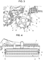
- Figure number 3.- shows a side view of the roller and the supporting structure of the machine with the device of the invention.
- Figure number 4.- shows a totally front elevation view of the roller, the inclination of rubber elements incorporating protruding at each end being appreciated.
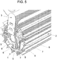
- And figure number 5.- shows, again a frontolateral perspective view, more enlarged, of the end of the roller in which the device of the invention is incorporated.
- In the light of the said figures, and according to their numbering, it can be seen on them a non-limiting example of the proposed vibration isolation device for agricultural machines, which comprises the parts and elements that are indicated and described in detail below.
- Thus, according to said figures, it can be seen how the device (1) in question, which is designed to be incorporated in an agricultural machine or similar, of which comprise at least one roller (2) coupled to it by means of a supporting structure (3) to which it is fastened at the ends thereof, which may or may not be provided with blades (4) or other working tools on its surface, the device (1) serving as an isolating means of the vibration that occurs when the roller (2) is dragged along the ground in a direction transverse to the longitudinal shaft (5) of rotation of said roller (2), it is formed, essentially, from two crowns (6) that are incorporated, opposed, one at each end of the roller (2), between the bearing support of its shaft (5) and the corresponding end of the supporting structure (3), each having several rubber isolating elements (7) distributed radially around it and secured, between respective pairs of flanges (8, 9) that fasten them, respectively, to said bearing support of the roller (5) shaft (5) and to the end of the supporting structure (3), so that they constitute a flexible link between both elements.
- More specifically, the rubber isolating elements (7) are formed by a flat piece or disk, and each of them is fastened, as a sandwich, between an inner flange (8), which is anchored to the rotating bearing support itself of the shaft (5) of the roller (2), and an outer flange (9) that is fastened to the end of the supporting structure (3).
- Also, these flanges (8, 9) have an inclined arrangement with respect to the plane of the crown (6) which, in turn, adopt the rubber isolating elements (7), which inclination, may or may not be constant in all of them , is variable in each case depending on the needs of use of the machine, since, the greater coplanarity with respect to the shaft (5) of rotation of the roller (2), greater isolation of vibrations but less mechanical resistance and, the greater the perpendicularity with respect to said shaft (5), less vibration isolation but greater mechanical resistance.
- Optionally, the flanges, at least the outer ones (9) can be mobile, for example by means of screwing, in order to allow a slight modification of the inclination thereof and, consequently, of the rubber isolating elements (7).
- In any case, in the preferred embodiment, each crown (6) incorporates five rubber isolating elements (7), distributed equidistantly around it, although this should not be taken as a limitation, since the essential of the device is the fact of comprising, at each end of the roller (2), and secured with variable inclination between the bearing support of the shaft (5) and the corresponding end of the supporting structure (3), several rubber isolating elements (7) distributed radially to said shaft (5), so that they constitute a flexible link between both elements.
- Having sufficiently described the nature of the present invention, as well as a way of putting it into practice, it is not considered necessary to make a more extensive explanation in order that any expert in this area will understand its scope and the advantages that can be derived from it, making known that, within reason it could be put into practice in other embodiments differing in detail from that indicated by way of example, and which will obtain the same degree of protection, provided that they do not alter, change, or modify its fundamental principle.
Claims (8)
- VIBRATION ISOLATION DEVICE FOR AGRICULTURAL MACHINES, of which comprise at least one roller (2) coupled to it by means of a supporting structure (3) to which it is fastened at the ends thereof, and may or may not be provided with blades (4) or other working tools on its surface, which, applicable as an isolating means of the vibration that occurs when the roller (2) is dragged along the ground in a direction transverse to the longitudinal shaft (5) of rotation, is characterized by comprising at each end of the roller (2), and secured with variable inclination between the support of the bearing of the shaft (5) and the corresponding end of the supporting structure (3), several rubber isolating elements (7) distributed radially to said shaft (5), so that they constitute a flexible link between both elements.
- VIBRATION ISOLATION DEVICE FOR AGRICULTURAL MACHINES, according to claim 1, characterized in that the rubber isolating elements (7) are incorporated in two crowns (6) that are incorporated, opposed, one at each end of the roller (2), between the bearing support of its shaft (5) and the corresponding end of the supporting structure (3).
- VIBRATION ISOLATION DEVICE FOR AGRICULTURAL MACHINES, according to claim 2, characterized in that the isolating elements (7) secured between respective pairs of flanges (8, 9) that fasten them, respectively, to the bearing support of the shaft (5) of roller (2) and to the end of the supporting structure (3).
- VIBRATION ISOLATION DEVICE FOR AGRICULTURAL MACHINES, according to claim 3, characterized in that the rubber isolating elements (7) are formed by a flat piece or disk, and each of them is fastened, as a sandwich, between an inner flange (8), which is anchored to the rotating bearing support itself of the shaft (5) of the roller (2), and an outer flange (9) that is fastened to the end of the supporting structure (3).
- VIBRATION ISOLATION DEVICE FOR AGRICULTURAL MACHINES, according to claim 4, characterized in that the flanges (8, 9) have an inclined arrangement with respect to the plane of the crown (6) which, in turn, the rubber isolating elements (7) adopt.
- VIBRATION ISOLATION DEVICE FOR AGRICULTURAL MACHINES, according to any of claims 1 to 5, characterized in that all rubber isolating elements (7) of each end of the roller (2) have the same inclination.
- VIBRATION ISOLATION DEVICE FOR AGRICULTURAL MACHINES, according to claim 5, characterized in that, at least, the outer ones (9) are movable to allow to modify the inclination thereof and, consequently, of the rubber isolating elements (7).
- VIBRATION ISOLATION DEVICE FOR AGRICULTURAL MACHINES, according to claim 2, characterized in that each crown (6) incorporates five rubber isolating elements (7), equidistantly distributed around it.
Applications Claiming Priority (2)
| Application Number | Priority Date | Filing Date | Title |
|---|---|---|---|
| ES201631325U ES1170533Y (en) | 2016-11-08 | 2016-11-08 | VIBRATION INSULATION DEVICE IN AGRICULTURAL MACHINES |
| PCT/ES2017/070739 WO2018087410A1 (en) | 2016-11-08 | 2017-11-08 | Vibration isolation device for agricultural machines |
Publications (4)
| Publication Number | Publication Date |
|---|---|
| EP3552469A1 true EP3552469A1 (en) | 2019-10-16 |
| EP3552469A4 EP3552469A4 (en) | 2020-05-13 |
| EP3552469C0 EP3552469C0 (en) | 2023-09-13 |
| EP3552469B1 EP3552469B1 (en) | 2023-09-13 |
Family
ID=57290841
Family Applications (1)
| Application Number | Title | Priority Date | Filing Date |
|---|---|---|---|
| EP17869605.0A Active EP3552469B1 (en) | 2016-11-08 | 2017-11-08 | Vibration isolation device for agricultural machines |
Country Status (6)
| Country | Link |
|---|---|
| EP (1) | EP3552469B1 (en) |
| BR (1) | BR212019009425U2 (en) |
| ES (1) | ES1170533Y (en) |
| RU (1) | RU2751174C2 (en) |
| UA (1) | UA126568C2 (en) |
| WO (1) | WO2018087410A1 (en) |
Cited By (1)
| Publication number | Priority date | Publication date | Assignee | Title |
|---|---|---|---|---|
| RU196568U1 (en) * | 2019-12-09 | 2020-03-05 | Федеральное государственное бюджетное образовательное учреждение высшего образования "Кубанский государственный аграрный университет им. И.Т. Трубилина" | Vibratory roller |
Family Cites Families (12)
| Publication number | Priority date | Publication date | Assignee | Title |
|---|---|---|---|---|
| US1980580A (en) * | 1933-05-13 | 1934-11-13 | Laval Separator Co De | Guide bearing for spindles of centrifuges |
| SE410546B (en) * | 1977-04-14 | 1979-10-22 | Stark Crister | DEVICE AT RINGVELT |
| SE501706C2 (en) * | 1990-11-05 | 1995-04-24 | Vaederstad Verken Ab | Disc tool for earthworking - has frame with downwardly directed arms and bearings supporting rotatable disc unit |
| US5678930A (en) * | 1996-02-12 | 1997-10-21 | Case Corporation | Improved bearing assembly permitting tri-axial movement |
| US5713418A (en) * | 1996-07-18 | 1998-02-03 | Warren Power Attachments | Vibratory compactor |
| US6244355B1 (en) * | 1999-11-30 | 2001-06-12 | Ronald H. Hall | Isolation mount |
| ES2233168B1 (en) * | 2003-02-21 | 2006-07-16 | Jose Gurri Molins | ELEMENT OF ABSORPTION AND ISOLATION OF BI-O-TRI-DIMENSIONAL MOVEMENT COMPONENTS, APPLICABLE TO MACHINES, DEVICES AND MECHANICAL IMPLEMENTS. |
| RU72114U1 (en) * | 2007-02-20 | 2008-04-10 | Общество с ограниченной ответственностью "БДМ-Агро" | SOIL SURFACE DEVICE |
| US7987917B1 (en) * | 2008-07-09 | 2011-08-02 | The United States Of America As Represented By The Secretary Of Agriculture | Multistage crop roller |
| SE541106C2 (en) * | 2012-08-22 | 2019-04-09 | Vaederstad Holding Ab | Suspension unit for agricultural implements, agricultural implements and use and procedure for mounting bearing unit |
| DK177697B1 (en) * | 2012-11-26 | 2014-03-17 | Dal Bo As | A device for stubble treatment |
| RU141027U1 (en) * | 2013-12-30 | 2014-05-27 | Федеральное государственное бюджетное образовательное учреждение высшего профессионального образования "Кубанский государственный аграрный университет" | VIBRATION ROLLER |
-
2016
- 2016-11-08 ES ES201631325U patent/ES1170533Y/en active Active
-
2017
- 2017-11-08 WO PCT/ES2017/070739 patent/WO2018087410A1/en not_active Ceased
- 2017-11-08 BR BR212019009425U patent/BR212019009425U2/en not_active Application Discontinuation
- 2017-11-08 EP EP17869605.0A patent/EP3552469B1/en active Active
- 2017-11-08 UA UAA201904868A patent/UA126568C2/en unknown
- 2017-11-08 RU RU2019114279A patent/RU2751174C2/en active
Cited By (1)
| Publication number | Priority date | Publication date | Assignee | Title |
|---|---|---|---|---|
| RU196568U1 (en) * | 2019-12-09 | 2020-03-05 | Федеральное государственное бюджетное образовательное учреждение высшего образования "Кубанский государственный аграрный университет им. И.Т. Трубилина" | Vibratory roller |
Also Published As
| Publication number | Publication date |
|---|---|
| BR212019009425U2 (en) | 2019-10-01 |
| EP3552469C0 (en) | 2023-09-13 |
| ES1170533U (en) | 2016-11-22 |
| WO2018087410A1 (en) | 2018-05-17 |
| EP3552469A4 (en) | 2020-05-13 |
| RU2019114279A (en) | 2020-12-10 |
| RU2751174C2 (en) | 2021-07-09 |
| ES1170533Y (en) | 2017-02-13 |
| UA126568C2 (en) | 2022-11-02 |
| EP3552469B1 (en) | 2023-09-13 |
| RU2019114279A3 (en) | 2020-12-11 |
Similar Documents
| Publication | Publication Date | Title |
|---|---|---|
| US20150181806A1 (en) | Shock absorption device of safety plate for shrub trimmer | |
| EP3332999B1 (en) | Engine device support structure and engine device installation method | |
| EP2923551B1 (en) | Blade mounting structure of lawn mower | |
| EP3552469B1 (en) | Vibration isolation device for agricultural machines | |
| EP2922382B1 (en) | A device for stubble treatment and a vibration-absorbing arrangement thereof | |
| AU2018237288B2 (en) | Suspension assembly for a machine | |
| US10106936B2 (en) | Vibration isolation for compactor | |
| JP2012039941A (en) | Grass mower | |
| JP6656003B2 (en) | Farm work machine | |
| EP2723155B1 (en) | Walk behind garden tool chassis | |
| KR20140095885A (en) | Shank link rotation type's vabratory ripper | |
| JP5876357B2 (en) | Rotary tiller | |
| JP2013183637A (en) | Working machine | |
| JP2019146508A (en) | Self-travel implement | |
| KR101273866B1 (en) | Walk-behind work machine | |
| KR102363695B1 (en) | Frame Apparatus of Agricultural Vehicle | |
| US10266213B2 (en) | Tractor | |
| KR20200066805A (en) | Vibration ripper having link structure improving vibration preventing function | |
| JP2019030237A (en) | Agricultural machine | |
| KR102363692B1 (en) | Frame Apparatus of Agricultural Vehicle | |
| JP2017006082A (en) | Agricultural implement | |
| KR102850497B1 (en) | The clutch assembly | |
| JP6909490B2 (en) | Agricultural work machine | |
| KR20160041219A (en) | Support apparatus for Harrow | |
| JP6542093B2 (en) | Work machine |
Legal Events
| Date | Code | Title | Description |
|---|---|---|---|
| STAA | Information on the status of an ep patent application or granted ep patent |
Free format text: STATUS: THE INTERNATIONAL PUBLICATION HAS BEEN MADE |
|
| PUAI | Public reference made under article 153(3) epc to a published international application that has entered the european phase |
Free format text: ORIGINAL CODE: 0009012 |
|
| STAA | Information on the status of an ep patent application or granted ep patent |
Free format text: STATUS: REQUEST FOR EXAMINATION WAS MADE |
|
| 17P | Request for examination filed |
Effective date: 20190606 |
|
| AK | Designated contracting states |
Kind code of ref document: A1 Designated state(s): AL AT BE BG CH CY CZ DE DK EE ES FI FR GB GR HR HU IE IS IT LI LT LU LV MC MK MT NL NO PL PT RO RS SE SI SK SM TR |
|
| AX | Request for extension of the european patent |
Extension state: BA ME |
|
| DAV | Request for validation of the european patent (deleted) | ||
| DAX | Request for extension of the european patent (deleted) | ||
| A4 | Supplementary search report drawn up and despatched |
Effective date: 20200409 |
|
| RIC1 | Information provided on ipc code assigned before grant |
Ipc: A01B 21/06 20060101AFI20200403BHEP |
|
| STAA | Information on the status of an ep patent application or granted ep patent |
Free format text: STATUS: EXAMINATION IS IN PROGRESS |
|
| 17Q | First examination report despatched |
Effective date: 20211029 |
|
| 17Q | First examination report despatched |
Effective date: 20211217 |
|
| 17Q | First examination report despatched |
Effective date: 20220316 |
|
| GRAP | Despatch of communication of intention to grant a patent |
Free format text: ORIGINAL CODE: EPIDOSNIGR1 |
|
| STAA | Information on the status of an ep patent application or granted ep patent |
Free format text: STATUS: GRANT OF PATENT IS INTENDED |
|
| INTG | Intention to grant announced |
Effective date: 20230418 |
|
| GRAJ | Information related to disapproval of communication of intention to grant by the applicant or resumption of examination proceedings by the epo deleted |
Free format text: ORIGINAL CODE: EPIDOSDIGR1 |
|
| GRAP | Despatch of communication of intention to grant a patent |
Free format text: ORIGINAL CODE: EPIDOSNIGR1 |
|
| INTG | Intention to grant announced |
Effective date: 20230615 |
|
| GRAS | Grant fee paid |
Free format text: ORIGINAL CODE: EPIDOSNIGR3 |
|
| GRAA | (expected) grant |
Free format text: ORIGINAL CODE: 0009210 |
|
| STAA | Information on the status of an ep patent application or granted ep patent |
Free format text: STATUS: THE PATENT HAS BEEN GRANTED |
|
| AK | Designated contracting states |
Kind code of ref document: B1 Designated state(s): AL AT BE BG CH CY CZ DE DK EE ES FI FR GB GR HR HU IE IS IT LI LT LU LV MC MK MT NL NO PL PT RO RS SE SI SK SM TR |
|
| REG | Reference to a national code |
Ref country code: GB Ref legal event code: FG4D |
|
| REG | Reference to a national code |
Ref country code: CH Ref legal event code: EP |
|
| REG | Reference to a national code |
Ref country code: DE Ref legal event code: R096 Ref document number: 602017074277 Country of ref document: DE |
|
| REG | Reference to a national code |
Ref country code: IE Ref legal event code: FG4D |
|
| U01 | Request for unitary effect filed |
Effective date: 20231011 |
|
| U07 | Unitary effect registered |
Designated state(s): AT BE BG DE DK EE FI FR IT LT LU LV MT NL PT SE SI Effective date: 20231019 |
|
| PG25 | Lapsed in a contracting state [announced via postgrant information from national office to epo] |
Ref country code: GR Free format text: LAPSE BECAUSE OF FAILURE TO SUBMIT A TRANSLATION OF THE DESCRIPTION OR TO PAY THE FEE WITHIN THE PRESCRIBED TIME-LIMIT Effective date: 20231214 |
|
| PG25 | Lapsed in a contracting state [announced via postgrant information from national office to epo] |
Ref country code: RS Free format text: LAPSE BECAUSE OF FAILURE TO SUBMIT A TRANSLATION OF THE DESCRIPTION OR TO PAY THE FEE WITHIN THE PRESCRIBED TIME-LIMIT Effective date: 20230913 Ref country code: NO Free format text: LAPSE BECAUSE OF FAILURE TO SUBMIT A TRANSLATION OF THE DESCRIPTION OR TO PAY THE FEE WITHIN THE PRESCRIBED TIME-LIMIT Effective date: 20231213 Ref country code: HR Free format text: LAPSE BECAUSE OF FAILURE TO SUBMIT A TRANSLATION OF THE DESCRIPTION OR TO PAY THE FEE WITHIN THE PRESCRIBED TIME-LIMIT Effective date: 20230913 Ref country code: GR Free format text: LAPSE BECAUSE OF FAILURE TO SUBMIT A TRANSLATION OF THE DESCRIPTION OR TO PAY THE FEE WITHIN THE PRESCRIBED TIME-LIMIT Effective date: 20231214 |
|
| U20 | Renewal fee for the european patent with unitary effect paid |
Year of fee payment: 7 Effective date: 20240117 |
|
| PG25 | Lapsed in a contracting state [announced via postgrant information from national office to epo] |
Ref country code: IS Free format text: LAPSE BECAUSE OF FAILURE TO SUBMIT A TRANSLATION OF THE DESCRIPTION OR TO PAY THE FEE WITHIN THE PRESCRIBED TIME-LIMIT Effective date: 20240113 |
|
| PG25 | Lapsed in a contracting state [announced via postgrant information from national office to epo] |
Ref country code: ES Free format text: LAPSE BECAUSE OF FAILURE TO SUBMIT A TRANSLATION OF THE DESCRIPTION OR TO PAY THE FEE WITHIN THE PRESCRIBED TIME-LIMIT Effective date: 20230913 |
|
| PG25 | Lapsed in a contracting state [announced via postgrant information from national office to epo] |
Ref country code: SM Free format text: LAPSE BECAUSE OF FAILURE TO SUBMIT A TRANSLATION OF THE DESCRIPTION OR TO PAY THE FEE WITHIN THE PRESCRIBED TIME-LIMIT Effective date: 20230913 Ref country code: RO Free format text: LAPSE BECAUSE OF FAILURE TO SUBMIT A TRANSLATION OF THE DESCRIPTION OR TO PAY THE FEE WITHIN THE PRESCRIBED TIME-LIMIT Effective date: 20230913 Ref country code: IS Free format text: LAPSE BECAUSE OF FAILURE TO SUBMIT A TRANSLATION OF THE DESCRIPTION OR TO PAY THE FEE WITHIN THE PRESCRIBED TIME-LIMIT Effective date: 20240113 Ref country code: ES Free format text: LAPSE BECAUSE OF FAILURE TO SUBMIT A TRANSLATION OF THE DESCRIPTION OR TO PAY THE FEE WITHIN THE PRESCRIBED TIME-LIMIT Effective date: 20230913 Ref country code: CZ Free format text: LAPSE BECAUSE OF FAILURE TO SUBMIT A TRANSLATION OF THE DESCRIPTION OR TO PAY THE FEE WITHIN THE PRESCRIBED TIME-LIMIT Effective date: 20230913 Ref country code: SK Free format text: LAPSE BECAUSE OF FAILURE TO SUBMIT A TRANSLATION OF THE DESCRIPTION OR TO PAY THE FEE WITHIN THE PRESCRIBED TIME-LIMIT Effective date: 20230913 |
|
| PG25 | Lapsed in a contracting state [announced via postgrant information from national office to epo] |
Ref country code: PL Free format text: LAPSE BECAUSE OF FAILURE TO SUBMIT A TRANSLATION OF THE DESCRIPTION OR TO PAY THE FEE WITHIN THE PRESCRIBED TIME-LIMIT Effective date: 20230913 |
|
| REG | Reference to a national code |
Ref country code: DE Ref legal event code: R097 Ref document number: 602017074277 Country of ref document: DE |
|
| REG | Reference to a national code |
Ref country code: CH Ref legal event code: PL |
|
| PG25 | Lapsed in a contracting state [announced via postgrant information from national office to epo] |
Ref country code: MC Free format text: LAPSE BECAUSE OF FAILURE TO SUBMIT A TRANSLATION OF THE DESCRIPTION OR TO PAY THE FEE WITHIN THE PRESCRIBED TIME-LIMIT Effective date: 20230913 |
|
| PG25 | Lapsed in a contracting state [announced via postgrant information from national office to epo] |
Ref country code: CH Free format text: LAPSE BECAUSE OF NON-PAYMENT OF DUE FEES Effective date: 20231130 |
|
| PLBE | No opposition filed within time limit |
Free format text: ORIGINAL CODE: 0009261 |
|
| STAA | Information on the status of an ep patent application or granted ep patent |
Free format text: STATUS: NO OPPOSITION FILED WITHIN TIME LIMIT |
|
| PG25 | Lapsed in a contracting state [announced via postgrant information from national office to epo] |
Ref country code: MC Free format text: LAPSE BECAUSE OF FAILURE TO SUBMIT A TRANSLATION OF THE DESCRIPTION OR TO PAY THE FEE WITHIN THE PRESCRIBED TIME-LIMIT Effective date: 20230913 Ref country code: CH Free format text: LAPSE BECAUSE OF NON-PAYMENT OF DUE FEES Effective date: 20231130 |
|
| 26N | No opposition filed |
Effective date: 20240614 |
|
| GBPC | Gb: european patent ceased through non-payment of renewal fee |
Effective date: 20231213 |
|
| REG | Reference to a national code |
Ref country code: IE Ref legal event code: MM4A |
|
| PG25 | Lapsed in a contracting state [announced via postgrant information from national office to epo] |
Ref country code: IE Free format text: LAPSE BECAUSE OF NON-PAYMENT OF DUE FEES Effective date: 20231108 |
|
| PG25 | Lapsed in a contracting state [announced via postgrant information from national office to epo] |
Ref country code: GB Free format text: LAPSE BECAUSE OF NON-PAYMENT OF DUE FEES Effective date: 20231213 |
|
| PG25 | Lapsed in a contracting state [announced via postgrant information from national office to epo] |
Ref country code: IE Free format text: LAPSE BECAUSE OF NON-PAYMENT OF DUE FEES Effective date: 20231108 Ref country code: GB Free format text: LAPSE BECAUSE OF NON-PAYMENT OF DUE FEES Effective date: 20231213 |
|
| U20 | Renewal fee for the european patent with unitary effect paid |
Year of fee payment: 8 Effective date: 20241107 |
|
| PG25 | Lapsed in a contracting state [announced via postgrant information from national office to epo] |
Ref country code: CY Free format text: LAPSE BECAUSE OF FAILURE TO SUBMIT A TRANSLATION OF THE DESCRIPTION OR TO PAY THE FEE WITHIN THE PRESCRIBED TIME-LIMIT; INVALID AB INITIO Effective date: 20171108 |
|
| PG25 | Lapsed in a contracting state [announced via postgrant information from national office to epo] |
Ref country code: HU Free format text: LAPSE BECAUSE OF FAILURE TO SUBMIT A TRANSLATION OF THE DESCRIPTION OR TO PAY THE FEE WITHIN THE PRESCRIBED TIME-LIMIT; INVALID AB INITIO Effective date: 20171108 |
|
| PG25 | Lapsed in a contracting state [announced via postgrant information from national office to epo] |
Ref country code: TR Free format text: LAPSE BECAUSE OF FAILURE TO SUBMIT A TRANSLATION OF THE DESCRIPTION OR TO PAY THE FEE WITHIN THE PRESCRIBED TIME-LIMIT Effective date: 20230913 |
|
| U20 | Renewal fee for the european patent with unitary effect paid |
Year of fee payment: 9 Effective date: 20251126 |
|
| U1N | Appointed representative for the unitary patent procedure changed after the registration of the unitary effect |
Representative=s name: DE CASTRO HERMIDA, JOSE LUIS; ES |