EP3552445B1 - Steuerkanalkonfiguration und taktung für autonome aufwärtsstrecke - Google Patents
Steuerkanalkonfiguration und taktung für autonome aufwärtsstrecke Download PDFInfo
- Publication number
- EP3552445B1 EP3552445B1 EP16923590.0A EP16923590A EP3552445B1 EP 3552445 B1 EP3552445 B1 EP 3552445B1 EP 16923590 A EP16923590 A EP 16923590A EP 3552445 B1 EP3552445 B1 EP 3552445B1
- Authority
- EP
- European Patent Office
- Prior art keywords
- control channel
- channel configuration
- control information
- autonomous uplink
- txop
- Prior art date
- Legal status (The legal status is an assumption and is not a legal conclusion. Google has not performed a legal analysis and makes no representation as to the accuracy of the status listed.)
- Active
Links
Images


Classifications
-
- H—ELECTRICITY
- H04—ELECTRIC COMMUNICATION TECHNIQUE
- H04L—TRANSMISSION OF DIGITAL INFORMATION, e.g. TELEGRAPHIC COMMUNICATION
- H04L5/00—Arrangements affording multiple use of the transmission path
- H04L5/003—Arrangements for allocating sub-channels of the transmission path
- H04L5/0053—Allocation of signalling, i.e. of overhead other than pilot signals
-
- H—ELECTRICITY
- H04—ELECTRIC COMMUNICATION TECHNIQUE
- H04W—WIRELESS COMMUNICATION NETWORKS
- H04W74/00—Wireless channel access
- H04W74/002—Transmission of channel access control information
-
- H—ELECTRICITY
- H04—ELECTRIC COMMUNICATION TECHNIQUE
- H04L—TRANSMISSION OF DIGITAL INFORMATION, e.g. TELEGRAPHIC COMMUNICATION
- H04L1/00—Arrangements for detecting or preventing errors in the information received
- H04L1/12—Arrangements for detecting or preventing errors in the information received by using return channel
- H04L1/16—Arrangements for detecting or preventing errors in the information received by using return channel in which the return channel carries supervisory signals, e.g. repetition request signals
- H04L1/18—Automatic repetition systems, e.g. Van Duuren systems
- H04L1/1812—Hybrid protocols; Hybrid automatic repeat request [HARQ]
- H04L1/1819—Hybrid protocols; Hybrid automatic repeat request [HARQ] with retransmission of additional or different redundancy
-
- H—ELECTRICITY
- H04—ELECTRIC COMMUNICATION TECHNIQUE
- H04L—TRANSMISSION OF DIGITAL INFORMATION, e.g. TELEGRAPHIC COMMUNICATION
- H04L27/00—Modulated-carrier systems
- H04L27/0006—Assessment of spectral gaps suitable for allocating digitally modulated signals, e.g. for carrier allocation in cognitive radio
-
- H—ELECTRICITY
- H04—ELECTRIC COMMUNICATION TECHNIQUE
- H04L—TRANSMISSION OF DIGITAL INFORMATION, e.g. TELEGRAPHIC COMMUNICATION
- H04L5/00—Arrangements affording multiple use of the transmission path
- H04L5/003—Arrangements for allocating sub-channels of the transmission path
- H04L5/0048—Allocation of pilot signals, i.e. of signals known to the receiver
- H04L5/0051—Allocation of pilot signals, i.e. of signals known to the receiver of dedicated pilots, i.e. pilots destined for a single user or terminal
-
- H—ELECTRICITY
- H04—ELECTRIC COMMUNICATION TECHNIQUE
- H04L—TRANSMISSION OF DIGITAL INFORMATION, e.g. TELEGRAPHIC COMMUNICATION
- H04L5/00—Arrangements affording multiple use of the transmission path
- H04L5/003—Arrangements for allocating sub-channels of the transmission path
- H04L5/0053—Allocation of signalling, i.e. of overhead other than pilot signals
- H04L5/0055—Physical resource allocation for ACK/NACK
-
- H—ELECTRICITY
- H04—ELECTRIC COMMUNICATION TECHNIQUE
- H04W—WIRELESS COMMUNICATION NETWORKS
- H04W72/00—Local resource management
- H04W72/04—Wireless resource allocation
- H04W72/044—Wireless resource allocation based on the type of the allocated resource
- H04W72/0446—Resources in time domain, e.g. slots or frames
-
- H—ELECTRICITY
- H04—ELECTRIC COMMUNICATION TECHNIQUE
- H04W—WIRELESS COMMUNICATION NETWORKS
- H04W72/00—Local resource management
- H04W72/20—Control channels or signalling for resource management
- H04W72/21—Control channels or signalling for resource management in the uplink direction of a wireless link, i.e. towards the network
-
- H—ELECTRICITY
- H04—ELECTRIC COMMUNICATION TECHNIQUE
- H04W—WIRELESS COMMUNICATION NETWORKS
- H04W72/00—Local resource management
- H04W72/20—Control channels or signalling for resource management
- H04W72/23—Control channels or signalling for resource management in the downlink direction of a wireless link, i.e. towards a terminal
- H04W72/232—Control channels or signalling for resource management in the downlink direction of a wireless link, i.e. towards a terminal the control data signalling from the physical layer, e.g. DCI signalling
-
- H—ELECTRICITY
- H04—ELECTRIC COMMUNICATION TECHNIQUE
- H04W—WIRELESS COMMUNICATION NETWORKS
- H04W74/00—Wireless channel access
- H04W74/08—Non-scheduled access, e.g. ALOHA
- H04W74/0808—Non-scheduled access, e.g. ALOHA using carrier sensing, e.g. carrier sense multiple access [CSMA]
-
- H—ELECTRICITY
- H04—ELECTRIC COMMUNICATION TECHNIQUE
- H04W—WIRELESS COMMUNICATION NETWORKS
- H04W72/00—Local resource management
- H04W72/04—Wireless resource allocation
- H04W72/044—Wireless resource allocation based on the type of the allocated resource
Definitions
- the following relates generally to wireless communication and more specifically to scheduling and control channel design for autonomous uplink.
- Wireless communications systems are widely deployed to provide various types of communication content such as voice, video, packet data, messaging, broadcast, and so on. These systems may be capable of supporting communication with multiple users by sharing the available system resources (e.g., time, frequency, and power).
- multiple-access systems include code division multiple access (CDMA) systems, time division multiple access (TDMA) systems, frequency division multiple access (FDMA) systems, and orthogonal frequency division multiple access (OFDMA) systems, (e.g., a Long Term Evolution (LTE) system, or a New Radio (NR) system).
- CDMA code division multiple access
- TDMA time division multiple access
- FDMA frequency division multiple access
- OFDMA orthogonal frequency division multiple access
- LTE Long Term Evolution
- NR New Radio
- a wireless multiple-access communications system may include a number of base stations or access network nodes, each simultaneously supporting communication for multiple communication devices, which may be otherwise known as user equipment (UE).
- UE user equipment
- a UE may transmit uplink communications with a prior assignment or grant of resources.
- a base station may need to detect the autonomous uplink transmission and determine certain information about the transmission in order to properly receive it.
- efficient coordination and control channel configurations may be desirable when autonomous uplink communications are employed.
- US 2016/037352 A1 relates to techniques for wireless communications over a shared radio frequency spectrum band, which may include techniques for transmitting uplink data transmissions using allocated uplink resources.
- Allocated uplink resources may include an uplink channel comprising a number of allocated interlaces of resource blocks (RBs) for use by a user equipment (UE). An incoming data stream may be processed and data separated into each of the allocated interlaces of RBs for the UE.
- WO 2016/072218 A1 relates to uplink communication in unlicensed bands in a radio communication system that runs LTE in unlicensed bands.
- the disclosure provides a control section that controls the transmission of an uplink signal in a first frequency carrier by executing Listen Before Talk, and a transmitting/receiving section that receives a downlink signal that is transmitted from a radio base station in the first frequency carrier, and the control section executes Listen Before Talk at an OFDM symbol timing in a subframe of the first frequency carrier, and, if the received power in the LBT period is equal to or lower than a predetermined threshold and the downlink signal is not detected, the control section detects that the subframe is not used to transmit the downlink signal, and controls the uplink signal to be transmitted in this subframe.
- the described techniques relate to improved methods, systems, devices, or apparatuses that support control channel configurations and timing for autonomous uplink transmission.
- the described techniques provide for various autonomous uplink control channel configurations for use with unscheduled uplink transmissions.
- a user equipment UE
- the UE may identify an autonomous uplink control channel configuration for the uplink transmission, and transmit control information and data during an initial transmission time interval (TTI) of a transmission opportunity (TxOP) according to the autonomous uplink control channel configuration.
- TTI initial transmission time interval
- TxOP transmission opportunity
- the autonomous uplink control channel configuration control may include a number of different waveforms and payload configurations.
- an autonomous uplink control channel configuration may include control information frequency division multiplexed with data and transmitted in a frequency interlace of a carrier bandwidth.
- the autonomous uplink control channel configuration may also include control information time division multiplexed with data and transmitted over a set of symbol periods of the initial TTI, where the control information and data may be transmitted in a frequency interlace or a set of frequency interlaces of a carrier bandwidth.
- the autonomous uplink control channel configuration may include a symbol period used for the receipt of a clear-to-send (CTS) signal from the base station followed by one or more symbols used as a guard period before the transmission of data.
- CTS clear-to-send
- a method of wireless communication may include identifying an autonomous uplink control channel configuration for unscheduled uplink transmissions in an unlicensed radio frequency spectrum band, transmitting control information multiplexed with data according to the autonomous uplink control channel configuration in the unlicensed radio frequency spectrum band during an initial TTI of a TxOP, and transmitting additional data in the unlicensed radio frequency spectrum band during one or more subsequent TTIs of the TxOP.
- the apparatus may include means for identifying an autonomous uplink control channel configuration for unscheduled uplink transmissions in an unlicensed radio frequency spectrum band, means for transmitting control information multiplexed with data according to the autonomous uplink control channel configuration in the unlicensed radio frequency spectrum band during an initial TTI of a TxOP, and means for transmitting additional data in the unlicensed radio frequency spectrum band during one or more subsequent TTIs of the TxOP.
- the apparatus may include a processor, memory in electronic communication with the processor, and instructions stored in the memory.
- the instructions may be operable by the processor to cause the apparatus to identify an autonomous uplink control channel configuration for unscheduled uplink transmissions in an unlicensed radio frequency spectrum band, transmit control information multiplexed with data according to the autonomous uplink control channel configuration in the unlicensed radio frequency spectrum band during an initial TTI of a TxOP, and transmit additional data in the unlicensed radio frequency spectrum band during one or more subsequent TTIs of the TxOP.
- identifying the autonomous uplink control channel configuration comprises: identifying a narrow bandwidth portion of the unlicensed radio frequency spectrum band, wherein the control information may be transmitted in the narrow bandwidth portion and the control information may be frequency division multiplexed with the data during the initial TTI of the TxOP.
- the narrow bandwidth portion comprises a frequency interlace of a carrier bandwidth.
- the autonomous uplink control channel configuration comprises a payload and a waveform that correspond to an enhanced physical uplink control channel (ePUCCH).
- ePUCCH enhanced physical uplink control channel
- identifying the autonomous uplink control channel configuration comprises: identifying one or more modulation symbol periods of the initial TTI, wherein the control information may be transmitted during the one or more modulation symbol periods and the control information may be time division multiplexed with the data during the initial TTI of the TxOP.
- the control information and the data in the initial TTI may be transmitted in a plurality of frequency interlaces of the unlicensed radio frequency spectrum band.
- the autonomous uplink control channel configuration comprises four modulation symbol periods, the four modulation symbol periods comprising two modulation symbol periods associated with a DMRS and two modulation symbol periods associated with data transmissions.
- the autonomous uplink control channel configuration comprises a payload and a waveform that correspond to an sPUCCH.
- transmitting the additional data comprises: transmitting the additional data during a subsequent modulation symbol period following the four modulation symbol periods within the plurality of frequency interlaces.
- the autonomous uplink control channel configuration comprises two modulation symbol periods, the two modulation symbol periods comprising a first modulation symbol periods associated with a DMRS and a second modulation symbol associated with data transmissions.
- transmitting the additional data comprises: transmitting the additional data during a subsequent modulation symbol period following the two modulation symbol periods within the plurality of frequency interlaces.
- Some examples of the method, apparatus, and non-transitory computer-readable medium described above may further include processes, features, means, or instructions for receiving a CTS signal from a base station during a modulation symbol period of the initial TTI of the TxOP, wherein the CTS signal may be responsive to the control information.
- Some examples of the method, apparatus, and non-transitory computer-readable medium described above may further include processes, features, means, or instructions for identifying a guard period between the modulation symbol period that includes the CTS signal and the data, wherein the guard period may be time division multiplexed with the control information, the CTS signal, and the data.
- transmitting the additional data comprises: transmitting the additional data during a subsequent modulation symbol period following the guard period.
- the control information and the data in the initial TTI may be transmitted and the CTS signal may be received in a plurality of interlaces of the unlicensed radio frequency spectrum band.
- the autonomous uplink control channel configuration comprises an initial modulation symbol period associated with a DMRS.
- the control information comprises at least one of a scheduling request (SR), an indication of a modulation and coding scheme (MCS), or hybrid automatic repeat request (HARQ) information, or a combination thereof.
- the data in the initial TTI of the TxOP and the additional data in the one or more subsequent TTIs of the TxOP may be transmitted with a same modulation and coding scheme (MCS).
- MCS modulation and coding scheme
- the data in the initial TTI of the TxOP may be transmitted with a first MCS and the additional data in the one or more subsequent TTIs of the TxOP may be transmitted with a second MCS that may be different from the first MCS.
- the data transmitted in the initial TTI of the TxOP comprises an indication of a MCS for the initial TTI and the additional data transmitted in the one or more subsequent TTIs of the TxOP comprise an indication of an MCS for each respective TTI of the TxOP.
- Some examples of the method, apparatus, and non-transitory computer-readable medium described above may further include processes, features, means, or instructions for identifying a hybrid automatic repeat request (HARQ) identifier, an indication of a redundancy version (RV), and a new data indicator (NDI) associated with each TTI of the TxOP.
- Some examples of the method, apparatus, and non-transitory computer-readable medium described above may further include processes, features, means, or instructions for transmitting an indication of the identified HARQ identifier, indication of the RV, and NDI for each TTI during the initial TTI of the TxOP.
- Some examples of the method, apparatus, and non-transitory computer-readable medium described above may further include processes, features, means, of instructions for identifying a NDI associated with each TTI of the TxOP. Some examples of the method, apparatus, and non-transitory computer-readable medium described above may further include processes, features, means, or instructions for transmitting an indication of the identified NDI associated with each TTI during the initial TTI of the TxOP. Some examples of the method, apparatus, and non-transitory computer-readable medium described above may further include processes, features, means, or instructions for transmitting a HARQ identifier and an indication of a RV during the initial TTI of the TxOP.
- Some examples of the method, apparatus, and non-transitory computer-readable medium described above may further include processes, features, means, of instructions for performing a clear channel assessment (CCA) procedure in the unlicensed radio frequency spectrum band during a preceding TTI before the TxOP.
- Some examples of the method, apparatus, and non-transitory computer-readable medium described above may further include processes, features, means, or instructions for transmitting a busy signal in the unlicensed radio frequency spectrum band upon completing the CCA procedure and for a remaining duration of the preceding TTI.
- CCA clear channel assessment
- Some examples of the method, apparatus, and non-transitory computer-readable medium described above may further include processes, features, means, or instructions for monitoring the unlicensed radio frequency spectrum band for one or more modulation symbol periods of the initial TTI, wherein the control information may be transmitted after the one or more modulation symbol periods of the initial TTI.
- Some examples of the method, apparatus, and non-transitory computer-readable medium described above may further include processes, features, means, or instructions for determining that no cell-specific reference signal (CRS) may be received from a serving base station during the one or more modulation symbol periods of the initial TTI, wherein the control information may be transmitted based at least in part on the determination that no CRS may be received.
- CRS cell-specific reference signal
- the method may include identifying an autonomous uplink control channel configuration for unscheduled uplink transmissions in an unlicensed radio frequency spectrum band, receiving control information multiplexed with data according to the autonomous uplink control channel configuration in the unlicensed radio frequency spectrum band during an initial TTI of a TxOP, and receiving additional data in the unlicensed radio frequency spectrum band during one or more subsequent TTIs of the TxOP.
- the apparatus may include means for identifying an autonomous uplink control channel configuration for unscheduled uplink transmissions in an unlicensed radio frequency spectrum band, means for receiving control information multiplexed with data according to the autonomous uplink control channel configuration in the unlicensed radio frequency spectrum band during an initial TTI of a TxOP, and means for receiving additional data in the unlicensed radio frequency spectrum band during one or more subsequent TTIs of the TxOP.
- the apparatus may include a processor, memory in electronic communication with the processor, and instructions stored in the memory.
- the instructions may be operable by the processor to cause the apparatus to identify an autonomous uplink control channel configuration for unscheduled uplink transmissions in an unlicensed radio frequency spectrum band, receive control information multiplexed with data according to the autonomous uplink control channel configuration in the unlicensed radio frequency spectrum band during an initial TTI of a TxOP, and receive additional data in the unlicensed radio frequency spectrum band during one or more subsequent TTIs of the TxOP.
- the non-transitory computer-readable medium may include instructions operable to identify an autonomous uplink control channel configuration for unscheduled uplink transmissions in an unlicensed radio frequency spectrum band, receive control information multiplexed with data according to the autonomous uplink control channel configuration in the unlicensed radio frequency spectrum band during an initial TTI of a TxOP, and receive additional data in the unlicensed radio frequency spectrum band during one or more subsequent TTIs of the TxOP.
- Some examples of the method, apparatus, and non-transitory computer-readable medium described above may further include processes, features, means, or instructions for determining whether the additional data may have been successfully received. Some examples of the method, apparatus, and non-transitory computer-readable medium described above may further include processes, features, means, or instructions for transmitting a feedback message comprising an acknowledgment or negative acknowledgment message based at least in part on the determination. In some examples of the method, apparatus, and non-transitory computer-readable medium described above, the feedback message may be transmitted using DCI format 0A, 0B, 4A, or 4B.
- Some examples of the method, apparatus, and non-transitory computer-readable medium described above may further include processes, features, means, or instructions for receiving, within the control information, a scheduling request (SR) associated with a UE. Some examples of the method, apparatus, and non-transitory computer-readable medium described above may further include processes, features, means, or instructions for determining that the additional data will be transmitted from the UE based at least in part on the received SR.
- SR scheduling request
- identifying the autonomous uplink control channel configuration comprises: identifying one or more modulation symbol periods of the initial TTI, wherein the control information may be transmitted during the one or more modulation symbol periods and the control information may be time division multiplexed with the data during the initial TTI of the TxOP.
- the control information and the data in the initial TTI may be received in a narrow bandwidth portion of the unlicensed radio frequency spectrum band.
- the narrow bandwidth portion comprises a frequency interlace of a carrier bandwidth.
- the autonomous uplink control channel configuration comprises four modulation symbol periods, the four modulation symbol periods comprising two modulation symbol periods associated with a DMRS and two modulation symbol periods associated with data transmissions.
- the autonomous uplink control channel configuration comprises a payload and a waveform that correspond to an sPUCCH.
- receiving the additional data comprises: receiving the additional data during a subsequent modulation symbol period following the four modulation symbol periods.
- the control information and the data in the initial TTI may be received in a plurality of frequency interlaces of the unlicensed radio frequency spectrum band.
- the autonomous uplink control channel configuration comprises four modulation symbol periods, the four modulation symbol periods comprising two modulation symbol periods associated with a DMRS and two modulation symbol periods associated with data transmissions.
- the autonomous uplink control channel configuration comprises a payload and a waveform that correspond to an sPUCCH.
- receiving the additional data comprises: receiving the additional data during a subsequent modulation symbol period following the four modulation symbol periods within the plurality of frequency interlaces.
- the autonomous uplink control channel configuration comprises two modulation symbol periods, the two modulation symbol periods comprising a first modulation symbol periods associated with a DMRS and a second modulation symbol associated with data transmissions.
- receiving the additional data comprises: receiving the additional data during a subsequent modulation symbol period following the two modulation symbol periods within the plurality of frequency interlaces.
- Some examples of the method, apparatus, and non-transitory computer-readable medium described above may further include processes, features, means, or instructions for transmitting a CTS signal to a UE during a modulation symbol period of the initial TTI of the TxOP, wherein the CTS signal may be responsive to the control information.
- Some examples of the method, apparatus, and non-transitory computer-readable medium described above may further include processes, features, means, or instructions for identifying a guard period between the modulation symbol period that includes the CTS signal and the data, wherein the guard period may be time division multiplexed with the control information, the CTS signal, and the data.
- receiving the additional data comprises: receiving the additional data during a subsequent modulation symbol period following the guard period.
- the control information and the data in the initial TTI may be received and the CTS signal may be transmitted in a plurality of interlaces of the unlicensed radio frequency spectrum band.
- the autonomous uplink control channel configuration comprises an initial modulation symbol period associated with a DMRS.
- the control information comprises at least one of an SR, an indication of a MCS, or HARQ information, or a combination thereof.
- Some examples of the method, apparatus, and non-transitory computer-readable medium described above may further include processes, features, means, or instructions for transmitting RRC signaling indicative of the autonomous uplink control channel configuration, wherein the autonomous uplink control channel configuration may be identified based at least in part on the RRC signaling.
- the RRC signaling comprises an indication of at least one of a frequency domain allocation, a DMRS configuration, or an OCC sequence, or any combination thereof.
- the control information may be received in a narrow bandwidth portion of the unlicensed radio frequency spectrum band comprising a frequency interlace of a carrier bandwidth.
- the autonomous uplink control channel configuration comprises fourteen modulation symbol periods, the fourteen modulation symbol periods comprising four modulation symbol periods associated with a DMRS and ten modulation symbol periods associated with data transmissions.
- the autonomous uplink control channel configuration comprises a payload and a waveform that correspond to an ePUCCH.
- a UE 115 may infer that a change in a received signal strength indicator (RSSI) of a power meter indicates that a channel is occupied. Specifically, signal power that is concentrated in a certain bandwidth and exceeds a predetermined noise floor may indicate another wireless transmitter.
- a CCA also may include detection of specific sequences that indicate use of the channel. For example, another device may transmit a specific preamble prior to transmitting a data sequence.
- an LBT procedure may include a wireless node adjusting its own backoff window based on the amount of energy detected on a channel and/or the acknowledge/negative-acknowledge (ACK/NACK) feedback for its own transmitted packets as a proxy for collisions.
- ACK/NACK acknowledge/negative-acknowledge
- SFN system frame number
- Each frame may include ten 1 ms subframes numbered from 0 to 9.
- a subframe may be further divided into two 0.5 ms slots, each of which contains 6 or 7 modulation symbol periods (depending on the length of the cyclic prefix prepended to each symbol). Excluding the cyclic prefix, each symbol may contain 2048 sample periods.
- an eCC may utilize a different symbol duration than other CCs, which may include use of a reduced symbol duration as compared with symbol durations of the other CCs. A shorter symbol duration may be associated with increased subcarrier spacing.
- a TTI in an eCC may consist of one or multiple symbols. In some cases, the TTI duration (that is, the number of symbols in a TTI) may be variable. In some cases, an eCC may utilize a different symbol duration than other CCs, which may include use of a reduced symbol duration as compared with symbol durations of the other CCs. A shorter symbol duration is associated with increased subcarrier spacing.
- a UE 115 may benefit from operating in an autonomous (i.e., unscheduled) uplink mode.
- UEs 115 may use an autonomous control channel (e . g ., A-PUCCH) configuration as described herein.
- A-PUCCH autonomous control channel
- These A-PUCCH configurations may be configured according to UE 115 or system needs or constraints in various examples.
- a base station 105 may signal uplink transmission configurations for different UEs 115 using RRC or PDCCH.
- a configuration sent using RRC may be less complex, and may be associated with relatively long time-scale (e . g ., slow) configuration or reconfiguration procedures.
- a configuration sent using PDCCH (or C-PDCCH) may be associated with relatively short time-scale ( e . g ., fast) configuration or reconfiguration procedures.
- the choice of how the configuration is transmitted (e . g ., using RRC or PDCCH) may be determined based on system parameters or details.
- rules may be defined and used by a base station 105 to restrict unscheduled uplink transmissions so that these transmissions do not coincide with discovery reference signal (DRS) measurement timing configuration (DMTC) operations, RACH operations, or the like.
- DRS discovery reference signal
- DMTC measurement timing configuration
- the A-PUCCH configuration may use a waveform and payload similar to that of, for example, short PUCCH (sPUCCH).
- sPUCCH short PUCCH
- the A-PUCCH may, for instance, be transmitted over four symbols, with a transmission in the special subframe.
- An sPUCCH configuration may support small payloads, and have a user multiplexing capability configurable up to 12 users.
- the base station may dynamically trigger the sPUCCH based on the presence of a pending ACK or NACK.
- the base station may trigger the sPUCCH over a common PDCCH (C-PDCCH), where the common PDCCH may carry the subframe configuration.
- C-PDCCH common PDCCH
- the base station may detect a UE-specific DMRS through blind detection.
- the base station may blindly detect the presence of PUSCH identify a UE 115 based on detecting a UE-specific DMRS sequence identification.
- the actual performance of UE-specific DMRS detection may be unknown, as DMRS may be designed primarily for channel estimation rather than UE-specific DMRS detection.
- ID UE identifier
- a second technique may use SR based detection of the PUSCH.
- a UE-specific and resource-orthogonal SR may act as a PUSCH activation indicator, so the base station may not need to blindly detect the presence of the PUSCH.
- each UE 115 may be assigned an orthogonal SR resource, and when the base station detects the SR resource, the base station may then start channel estimation based DMRS and data decoding.
- SR may no longer be used for scheduling requests for UEs 115 operating according to autonomous uplink coordination.
- UE identification may be based on a mapping between the UE ID and a UE-specific SR resource.
- intra-cell UE ambiguity and transmission collisions may result in decreased system performance, for example, due to timing synchronization issues. Intra-cell UE ambiguity or transmission collisions may arise in scenarios where two or more UEs are unable to detect each other (e.g., hidden nodes as described above).
- the base station may detect the presence of the PUSCH and identify a UE 115 through a DMRS or SR.
- the base station may detect its PUSCH. However, because other intra-cell UEs may not detect the DMRS and SR from UE 115, another intra-cell UE (e . g ., an aggressor) may also successfully contend the medium. As a result, the base station may have a misaligned TDD configuration and frame start timing, which may result in a collision between the transmissions from the two UEs 115.Wireless communications system may support autonomous uplink control channel configurations for use in unscheduled uplink transmissions.
- a UE 115 may identify data to transmit to a base station 105, and may initiate an unscheduled uplink transmission (e . g ., without first receiving a grant of resources from the base station 105). Accordingly, the UE 115 may identify an autonomous uplink control channel configuration for the uplink transmission, and transmit control information and data during an initial TTI of a TxOP according to the autonomous uplink control channel configuration.
- an autonomous uplink control channel configuration control may include a number of different waveforms and payload configurations.
- an autonomous uplink control channel configuration may include control information frequency division multiplexed with data and transmitted in a frequency interlace of a carrier bandwidth.
- the autonomous uplink control channel configuration may also include control information time division multiplexed with data and transmitted over a set of symbol periods of the initial TTI, where the control information and data may be transmitted in a frequency interlace or a set of frequency interlaces of a carrier bandwidth.
- the autonomous uplink control channel configuration may include a symbol period used for the receipt of a CTS signal from the base station followed by one or more symbols used as a guard period before the transmission of data.
- FIG. 2 illustrates an example of a wireless communications system 200 that supports various control channel configurations for autonomous uplink.
- Wireless communications system 200 may include a base station 105-a and UE 115-a that may be examples of the corresponding devices described with reference to FIG. 1 .
- UE 115-a may be time-synchronized with base station 105-a, and may be capable of unscheduled or autonomous uplink transmissions to base station 105-a.
- wireless communications system 200 may enable the use of different autonomous uplink control channel configurations by UE 115-a to send control information to base station 105-a.
- autonomous uplink coordination may use a LBT procedure to resolve ambiguity between UEs 115 (e.g., including UE 115-a) and to mitigate potential for collisions that may arise in scenarios where un-scheduled wireless systems coexist with scheduled wireless systems.
- LBT procedure UE 115-a may monitor or sense a medium for energy over a defined time period to detect activity from other intra-cell UEs 115 (not shown).
- UE 115-a may win contention for a set of resources used for transmitting data, meaning that the medium is clear.
- UE 115-a wins contention it may transmit a busy signal until a subsequent TTI (e.g., a subframe, two-symbols, a slot, etc.).
- UE 115-a may perform a subsequent LBT procedure to determine whether base station 105-a is transmitting (e . g ., an intra-cell LBT). For example, UE 115-a may, after sending the busy signal, monitor the medium for activity by base station 105-a which may include the transmission of CRSs, a PDSCH, or a PDCCH. UE 115-a may perform the intra-cell LBT procedure for a certain duration that may be relatively short, including, for example, a duration of one or two symbols.
- UE 115-a may begin transmitting uplink data (e.g., using a PUSCH) at a symbol period following the intra-cell LBT procedure.
- uplink data e.g., using a PUSCH
- an autonomous PUCCH may be utilized to carry uplink control information 205, including, for example: an indication of an uplink MCS; HARQ information which may include an NDI, a HARQ identifier (HARQ ID), and a RV; and, optionally, a SR.
- the resource allocation may be configured on the frequency domain (i.e. , each frequency interlace) according to RRC signaling received from base station 105--a.
- the resource allocation may have a resource block (RB)-level granularity, accordingly allocating resources for each RB independently.
- the resource allocation further introduce frequency hopping across the subframe to improve detection performance.
- the RRC may further configure the DMRS, and orthogonal cover code (OCC) to provide additional orthogonality between layers.
- the configuration of the autonomous uplink control channel may use different waveforms and payloads.
- the A-PUCCH may utilize the waveform and payload similar to that of an ePUCCH.
- the A-PUCCH may utilize the waveform and payload similar to that of an sPUCCH. being a per-interlace allocation.
- the A-PUCCH may utilize a wideband-sPUCCH allocation, using a full-tone allocation where each interlace of the entire bandwidth may be allocated similarly.
- the A-PUCCH may utilize an alternate waveform, where the alternate waveform includes a wideband allocation of all interlaces. Intra-cell LBT may be applied before each of the above configurations of the A-PUCCH.
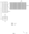
- FIG. 3 illustrates an example of a first autonomous control channel configuration 300 for autonomous uplink.
- the first autonomous control channel configuration 300 may be an example of a control channel used by a UE 115 for opportunistically transmitting uplink control and data to a base station 105 without receiving a prior grant of uplink resources.
- the first autonomous control channel configuration 300 may have a similar payload and wave form as an ePUCCH, and may be transmitted over a single frequency interlace.
- a system bandwidth may include one or more frequency interlaces 305.
- the TTI 302 may have a length or duration of, for example fourteen symbols 310 ( e.g., OFDM symbols), and TTI 302 may be an initial TTI of a TxOP.
- each subsequent TTI 302 of a TxOP may not include the first autonomous control channel configuration 300.
- First autonomous control channel configuration 300 may be configured by RRC signaling received from a base station 105, and the resource allocation of first autonomous control channel configuration 300 may be configured independently for each interlace 305. Accordingly, each interlace 305 may include a resource block having one or more resource elements (REs) 315. The resource allocation for interlaces 305 may allocate resources independently for each resource block (RB).
- REs resource elements
- Each RE 315 may consist of one symbol 310 and one subcarrier.
- each interlace 305 may include, for example, fourteen symbols 310. Of the fourteen symbols 310, four may be allocated as reference signal (RSs) REs 315, for example DMRSs. The remaining ten symbols 310 may be allocated as data REs 315.
- RSs reference signal
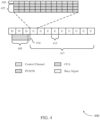
- FIG. 4 illustrates an example of a timeline 400 for an autonomous control channel transmission in a system that supports various control channel configurations for autonomous uplink.
- Timeline 400 may be an example of a transmission of the first autonomous control channel configuration 300 as described with reference to FIG. 3 .
- a UE 115 may initiate a CCA 405 to determine whether the transmission medium is available. If the channel is available, the UE 115 may transmit busy signal 410 to indicate that the channel is reserved by the UE 115 for the TxOP). Based on CCA 405, the UE 115 may initiate an uplink transmission.
- An initial TTI 415 e.g., an initial uplink subframe of a TxOP 417) of an autonomous uplink burst may carry uplink control information for the whole TxOP, and control information may not be transmitted in subsequent TTIs 415, for example, beginning from a second uplink TTI 415 of TxOP 417.
- An autonomous uplink control channel 420 in the initial TTI 415 may be frequency division multiplexed with PUSCH 425.
- an SR transmitted in the autonomous uplink control channel 420 may act as an activation indicator, or may be replaced with a UE-specific DMRS.
- the autonomous uplink control channel 420 may have a similar payload and waveform to that of an ePUCCH.
- MCS for multiple TTIs 415 different methods may be used. For example, one MCS may be indicated for the whole transmission opportunity (using, e.g. , 5 bits), where the same MCS is used in all TTIs 415. Alternatively, an initial MCS may be indicated for the initial TTI 415 and a further MCS may be indicated for the remaining TTIs 415 (using e.g., a total of 10 bits). In this alternative, the PUSCH 425 of the initial TTI 415 may be multiplexed with the autonomous uplink control channel 420. As another alternative, a bitmap may be used to indicate MCS for each TTI 415 (using, e.g ., 5 * n bits, where the transmission opportunity has n TTIs 415).
- Similar methods may be used to indicate uplink HARQ information for ePUCCH-like autonomous uplink control channels.
- one HARQ process may require more bits than MCS (e.g., 7 bits total, including 4 bits for HARQ ID, 2 bits for RV, and 1 bit for NDI).
- a bitmap may be used to indicate uplink HARQ information for each TTI 415 (using, e.g., 7 * n bits, where the transmission opportunity has n uplink TTIs 415).
- sequentially numbered identifiers may be used to indicate the HARQ ID and the NDI.
- HARQ ID and RV of the initial TTI 415 may be used, and may be numbered sequentially for each subsequent TTI 415.
- This alternative may further use a bitmap of the NDI for each TTI 415. This may use, for example, 6 + n bits for a number n HARQ processes.
- FIG. 5 illustrates an example of a second autonomous control channel configuration 500 that supports autonomous uplink.
- the second autonomous control channel configuration 500 may be an example of a control channel used by a UE 115 for opportunistically transmitting uplink control and data to a base station 105 without receiving a prior grant of uplink resources.
- the second autonomous control channel configuration 500 may have a similar payload and wave form as an sPUCCH and may be transmitted over a single frequency interlace.
- a system bandwidth may include one or more interlaces 505, and TTI 502 may be an initial subframe of a TxOP.
- the second autonomous control channel configuration 500 may include, for example, four symbols 510, with two symbols 510 used for DMRS, followed by two symbols 510 used as data symbols. After the TTI 502, each subsequent TTI 502 may have its own resource allocation and may not include second autonomous control channel configuration 500.
- the resource allocation of second autonomous control channel configuration 500 may be configured independently for each interlace 505.
- Each interlace 505 may include a resource block having one or more REs 515.
- the resource allocation for interlaces 505 may allocate resources independently for each RB.
- Each symbol 510 of the RB may be configured similarly to, for example in this case, sPUCCH.
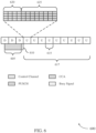
- FIG. 7 illustrates an example of a third autonomous control channel configuration 700 that supports autonomous uplink.
- the third autonomous control channel configuration 700 may be an example of a control channel used by a UE 115 for opportunistically transmitting uplink control and data to a base station 105 without receiving a prior grant of uplink resources.
- the third autonomous control channel configuration 700 may have a similar payload and wave form as a sPUCCH, and may be transmitted over a set of frequency interlaces.
- FIG. 8 illustrates an example of a timeline 800 for an autonomous control channel transmission in a system that supports various control channel configurations for autonomous uplink.
- Timeline 800 may be an example of a transmission of the third autonomous control channel configuration 700 as described with reference to FIG. 7 .
- a UE 115 may initiate a CCA procedure 805 to determine whether the transmission medium is available. If the channel is available, the UE 115 may transmit busy signal 810 to indicate that the channel is reserved for the transmission opportunity. Based on CCA procedure 805, the UE 115 may initiate an uplink transmission.
- An initial TTI 815 e.g., an initial uplink subframe of a TxOP 817) of an autonomous uplink burst may carry uplink control information for the whole transmission opportunity, and control information may not be transmitted in subsequent TTIs 815 of TxOP 817, for example, beginning from a second uplink TTI 815.
- an autonomous uplink control channel 820 in the first TTI 815 may be time division multiplexed with PUSCH 825.
- an SR transmitted in the autonomous uplink control channel 820 may act as an activation indicator, or may be replaced with a UE-specific DMRS.
- the autonomous uplink control channel 820 may have a similar payload and waveform to that of an sPUCCH.
- the first TTI 815 of an automated uplink burst may carry the uplink control information for the whole TxOP, and the A-PUCCH may not be transmitted in subsequent TTIs 815, for example, beginning from the second TTI 815.
- the PUSCH 825 transmission may start from the third symbol of the initial TTI 815. Additionally or alternatively, the PUSCH 825 transmission may start from the fifth symbol of the initial TTI 815 of TxOP 817, such as in the case where the autonomous uplink control channel 820 includes four modulation symbol periods.
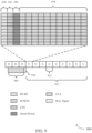
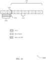
- FIG. 9 illustrates an example of a fourth autonomous control channel configuration 900 that supports autonomous uplink.
- the fourth autonomous control channel configuration 900 may be an example of an waveform, which may include certain symbol periods used for CTS transmissions by a base station and a guard period prior to data transmissions by a UE 115. Additionally, the timeframe illustrated in FIG. 9 and associated with the transmission of the fourth autonomous control channel configuration 900 may be similar to those described above with reference to FIGs. 4 , 6 , and 8 , and will not be repeated here for the sake of brevity.
- an autonomous uplink control channel configuration may utilize an alternate waveform, where the alternate waveform includes a wideband allocation of all frequency interlaces in a system bandwidth.
- the waveform may include a reference signal 920 transmission for all interlaces, which may include a DMRS that acts similar to a request-to-send (RTS) signal.
- the base station may identify a UE ID through DMRS sequence detection.
- the reference signal 920 may be followed by a one symbol preamble 925 for all interlaces, which may carry the uplink control information, where the preamble 925 may act similarly to a CTS.
- the preamble 925 may reserve the medium, or clean up the medium of conflicting transmissions.
- the preamble 925 may further resolve contentions from hidden nodes, with which the UE 115 is contending for access to the unlicensed radio frequency spectrum band, and intra-cell UE collisions.
- the above described methods for signaling MCS and uplink HARQ information may similarly be applied for autonomous uplink control channels utilizing the fourth autonomous control channel configuration 900.
- the preamble 925 may then be followed by a guard period 930 of one or more symbol periods for transition from downlink transmissions to uplink transmissions. In some cases, the length of the guard period 930 may be configured through RRC.
- a PUSCH 935 may be subsequently transmitted following the guard period 930 and subsequent TTIs 915 of TxOP 917 may not include an autonomous uplink control channel.
- the case in which the UE 115 does not detect a CRS or other activity for the defined duration may be referred to as a "win,” meaning that medium is clear and the UE 115 may begin transmitting data during TxOP 1007. That is, if the UE 115 "wins" the intra-cell LBT procedure, i.e., does not detect any activity during intra-cell LBT procedure 1020, the UE 115 may begin transmitting uplink data ( e.g., using a PUSCH). The UE 115 may thus begin transmitting uplink data at, for example, symbol 2 or 3, after the defined time period for intra-cell LBT procedure 1020.
- uplink data e.g., using a PUSCH
- a certain combination of bits may be used to indicate ACK/NACK feedback of autonomous uplink transmissions from a UE 115.
- an NDI bit may be used to indicate ACK/NACK feedback, and information associated with a HARQ identifier and RV may be indicated in bits corresponding to a HARQ process number bit and RV, respectively.
- FIG. 11 illustrates an example of a process flow 1100 in a system that supports various control channel configurations for autonomous uplink.
- Process flow 1100 may include a UE 115-b and base station 105-b, which may be respective examples of a UE 115 and a base station 105 as described herein with reference to FIGs. 1-2 .
- Process flow 1100 may be an example of the use of different autonomous uplink control channel configurations, where UE 115--b may opportunistically transmit uplink data without receiving a prior grant of uplink resources.
- base station 105-b may transmit to UE 115-b, and UE 115-b may receive from base station 105-b, an RRC message.
- the RRC message, or RRC signaling may indicate a periodic resource allocation in the frequency domain for uplink transmissions in an unlicensed radio frequency spectrum band.
- the resource allocation may have a resource block (RB) level granularity, accordingly allocating resources for each RB.
- the resource allocation further introduce frequency hopping across the subframe to improve detection performance.
- the RRC may further indicate a DMRS configuration and an OCC sequence.
- UE 115-b may identify an autonomous uplink control channel configuration for unscheduled uplink transmissions in an unlicensed radio frequency spectrum band.
- the control channel information may include an SR, a MCS, and HARQ information.
- the HARQ information may include a HARQ ID, a RV, and a NDI associated with each TTI ( e.g., each subframe) of the transmission opportunity.
- UE 115-b may further identify a narrow bandwidth portion of the unlicensed radio frequency spectrum band for transmission of control information.
- the narrow bandwidth portion of the frequency spectrum may include one or more particular frequency interlace of the carrier bandwidth.
- UE 115-b may further identify one or more modulation symbol periods of an initial TTI. An initial modulation symbol period may be used for DMRS.
- the control channel configuration may define a payload and waveform similar to that of ePUCCH.
- the control channel configuration may use, for example, fourteen modulation symbol periods. Four of the modulation symbol periods may be used for DMRS, and ten modulation symbol periods may be used for data transmissions.
- control channel configuration may define a payload and waveform similar to that of sPUCCH.
- the control channel configuration may use, for example, four modulation symbol periods. Two modulation symbol periods may be used for DMRS, and two modulation symbol periods may be used for data transmissions.
- the control channel configuration may use, for example, two modulation symbol periods, where the first modulation symbol period may be used for DMRS, and the second modulation symbol period may be used for data transmissions.
- UE 115-b may perform a CCA.
- UE 115-b may identify a CCA format for the autonomous uplink mode and perform a CCA procedure in the unlicensed radio frequency spectrum band prior to transmitting an uplink message using the identified CCA format.
- the CCA procedure may be performed, for example, during a TTI preceding the transmission opportunity.
- UE 115--b may further identify a guard period between the modulation symbol period that includes the CTS signal and the data. The guard period may be time division multiplexed with any of the control information, the CTS signal, and the data.
- UE 115-b may transmit to base station 105-b), and base station 105-b may receive from UE 115-b, a busy signal indicating that a portion of the unlicensed radio frequency spectrum band is reserved for transmission of the uplink message. Transmitting the busy signal may be based at least in part on UE 115-b identifying that the portion of the unlicensed radio frequency spectrum band is available based on the CCA. The busy signal may be transmitted in the unlicensed radio frequency spectrum band upon completing the CCA procedure and for the remaining duration of the preceding TTL
- UE 115-b may transmit to base station 105-b, and base station 105-b may receive from UE 115-b, control information multiplexed with data according to the autonomous uplink control channel configuration in the unlicensed radio frequency spectrum band.
- the control information may be transmitted during an initial TTI of a transmission opportunity. Additionally or alternatively, the control information and data may be transmitted during the identified one or more modulation symbol periods, and the control information may be time division multiplexed with the data.
- the transmitted data may include an indication of a MCS for the initial TTI.
- the transmitted data may further include an indicator for the identifier HARQ ID, RV, and NDI for each TTI of the transmission opportunity.
- the control information and the data may be transmitted in the identified narrow bandwidth portion, including one or more frequency interlaces, of the unlicensed radio frequency spectrum band, and the control information may be frequency division multiplexed with the data.
- UE 115-b may perform an LBT procedure in which UE 115-b may monitor the unlicensed radio frequency spectrum band for one or more modulation symbol periods of the initial TT1. UE 115-b may then transmit the control information after the one or more modulation symbol periods of the initial TTI based at least in part on determining that no CRS may have been received from base station 105-b (or, a serving base station) during the one or more modulation symbol periods of the initial TTI,
- base station 105-b may transmit to UE 115-b, and UE 115-b may receive from base station 105-b, a CTS signal during a modulation symbol period of the initial TTI of the transmission opportunity.
- the CTS signal may be transmitted on one or more particular interlaces of the unlicensed radio frequency spectrum band.
- the CTS signal may be responsive to the transmitted control information.
- UE 115-b may transmit to base station 105-b), and base station 105-b may receive from UE 115-b, additional data in the unlicensed radio frequency spectrum band during one or more subsequent TTIs of the transmission opportunity.
- the additional data may, for example, be transmitted on one or more frequency interlaces during a subsequent modulation symbol period following the two or four modulation symbol periods.
- the additional data may be transmitted during a subsequent modulation symbol period following the guard period.
- the data in the initial TTI and the additional data may be transmitted with the same MCS.
- the data in the initial TTI may be transmitted with a first MCS
- the additional data may be transmitted with a second MCS, where the second MCS may be different from the first MCS.
- the additional transmitted data may include an indication of a MCS for each respective TTI of the transmission opportunity.
- the additional transmitted data may further include an additional HARQ ID and an additional indication of an RV based at least in part on a sequential computation associated with each TTI of the transmission opportunity.
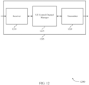
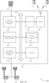
- FIG. 12 shows a block diagram 1200 of a wireless device 1205 that supports various control channel configurations for autonomous uplink in accordance with various aspects of the present disclosure.
- Wireless device 1205 may be an example of aspects of a UE 115 as described with reference to FIG. 1 .
- Wireless device 1205 may include receiver 1210, UE control channel manager 1215, and transmitter 1220.
- Wireless device 1205 may also include a processor. Each of these components may be in communication with one another ( e.g., via one or more buses).
- Receiver 1210 may receive information such as packets, user data, or control information associated with various information channels (e.g ., control channels, data channels, and information related to various control channel configurations for autonomous uplink, etc. ) . Information may be passed on to other components of the device.
- the receiver 1210 may be an example of aspects of the transceiver 1535 described with reference to FIG. 15 .
- UE control channel manager 1215 may be an example of aspects of the UE control channel manager 1515 described with reference to FIG. 15 .
- UE control channel manager 1215 or at least some of its various sub-components may be implemented in hardware, software executed by a processor, firmware, or any combination thereof. If implemented in software executed by a processor, the functions of the UE control channel manager 1215 and/or at least some of its various sub-components may be executed by a general-purpose processor, a digital signal processor (DSP), an application-specific integrated circuit (ASIC), an field-programmable gate array (FPGA) or other programmable logic device, discrete gate or transistor logic, discrete hardware components, or any combination thereof designed to perform the functions described in the present disclosure.
- DSP digital signal processor
- ASIC application-specific integrated circuit
- FPGA field-programmable gate array
- the UE control channel manager 1215 or at least some of its various sub-components may be physically located at various positions, including being distributed such that portions of functions are implemented at different physical locations by one or more physical devices.
- UE control channel manager 1215 or at least some of its various sub-components may be a separate and distinct component in accordance with various aspects of the present disclosure.
- UE control channel manager 1215 or at least some of its various sub-components may be combined with one or more other hardware components, including but not limited to an I/O component, a transceiver, a network server, another computing device, one or more other components described in the present disclosure, or a combination thereof in accordance with various aspects of the present disclosure.
- UE control channel manager 1215 may identify an autonomous uplink control channel configuration for unscheduled uplink transmissions in an unlicensed radio frequency spectrum band, transmit control information multiplexed with data according to the autonomous uplink control channel configuration in the unlicensed radio frequency spectrum band during an initial TTI of a TxOP, and transmit additional data in the unlicensed radio frequency spectrum band during one or more subsequent TTIs of the TxOP.
- Transmitter 1220 may transmit signals generated by other components of the device.
- the transmitter 1220 may be collocated with a receiver 1210 in a transceiver module.
- the transmitter 1220 may be an example of aspects of the transceiver 1535 described with reference to FIG. 15 .
- the transmitter 1220 may include a single antenna, or it may include a set of antennas.
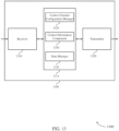
- Control channel configuration manager 1325 may identify an autonomous uplink control channel configuration for unscheduled uplink transmissions in an unlicensed radio frequency spectrum band.
- identifying the autonomous uplink control channel configuration may include identifying one or more modulation symbol periods of the initial TTI, where the control information is transmitted during the one or more modulation symbol periods and the control information is time division multiplexed with the data during the initial TTI of the TxOP.
- Identifying the autonomous uplink control channel configuration may also include identifying a narrow bandwidth portion of the unlicensed radio frequency spectrum band, where the control information is transmitted in the narrow bandwidth portion and the control information is frequency division multiplexed with the data during the initial TTI of the TxOP.
- the autonomous uplink control channel configuration includes four modulation symbol periods, the four modulation symbol periods including two modulation symbol periods associated with a DMRS and two modulation symbol periods associated with data transmissions. In some examples, the autonomous uplink control channel configuration includes two modulation symbol periods, the two modulation symbol periods including a first modulation symbol periods associated with a DMRS and a second modulation symbol associated with data transmissions. In some cases, the autonomous uplink control channel configuration includes four modulation symbol periods, the four modulation symbol periods including two modulation symbol periods associated with a DMRS and two modulation symbol periods associated with data transmissions.
- Control information component 1330 may transmit control information multiplexed with data according to the autonomous uplink control channel configuration in the unlicensed radio frequency spectrum band during an initial TTI of a TxOP.
- the control information and the data in the initial TTI are transmitted in a narrow bandwidth portion of the unlicensed radio frequency spectrum band.
- the narrow bandwidth portion includes a frequency interlace of a carrier bandwidth.
- the control information and the data in the initial TTI are transmitted in a set of frequency interlaces of the unlicensed radio frequency spectrum band.
- the control information and the data in the initial TTI are transmitted and the CTS signal is received in a set of interlaces of the unlicensed radio frequency spectrum band.
- the control information includes at least one of a SR, an indication of a MCS, or HARQ information, or a combination thereof.
- Data manager 1335 may transmit additional data in the unlicensed radio frequency spectrum band during one or more subsequent TTIs of the TxOP.
- transmitting the additional data includes: transmitting the additional data during a subsequent modulation symbol period following the four modulation symbol periods.
- transmitting the additional data includes: transmitting the additional data during a subsequent modulation symbol period following the four modulation symbol periods within the set of frequency interlaces.
- transmitting the additional data includes transmitting the additional data during a subsequent modulation symbol period following the two modulation symbol periods within the set of frequency interlaces.
- transmitting the additional data includes transmitting the additional data during a subsequent modulation symbol period following the guard period.
- the data in the initial TTI of the TxOP and the additional data in the one or more subsequent TTIs of the TxOP are transmitted with a same MCS. In some cases, the data in the initial TTI of the TxOP is transmitted with a first MCS and the additional data in the one or more subsequent TTIs of the TxOP is transmitted with a second MCS that is different from the first MCS. In some cases, the data transmitted in the initial TTI of the TxOP includes an indication of a MCS for the initial TTI and the additional data transmitted in the one or more subsequent TTIs of the TxOP include an indication of an MCS for each respective TTI of the TxOP.
- Transmitter 1320 may transmit signals generated by other components of the device.
- the transmitter 1320 may be collocated with a receiver 1310 in a transceiver module.
- the transmitter 1320 may be an example of aspects of the transceiver 1535 described with reference to FIG. 15 .
- the transmitter 1320 may include a single antenna, or it may include a set of antennas.
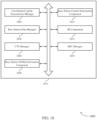
- FIG. 14 shows a block diagram 1400 of a UE control channel manager 1415 that supports various control channel configurations for autonomous uplink in accordance with various aspects of the present disclosure.
- the UE control channel manager 1415 may be an example of aspects of a UE control channel manager 1215, a UE control channel manager 1315, or a UE control channel manager 1515 described with reference to FIGs. 12 , 13 , and 15 .
- the UE control channel manager 1415 may include control channel configuration manager 1420, control information component 1425, data manager 1430, CTS component 1435, guard period component 1440, radio resource control (RRC) signaling component 1445, HARQ information component 1450, and listen-before-talk (LBT) manager 1455.
- RRC radio resource control
- LBT listen-before-talk
- Control channel configuration manager 1420 may identify an autonomous uplink control channel configuration for unscheduled uplink transmissions in an unlicensed radio frequency spectrum band.
- identifying the autonomous uplink control channel configuration may include identifying one or more modulation symbol periods of the initial TTI, where the control information is transmitted during one or more modulation symbol periods and control information is time division multiplexed with the data during the initial TTI of the TxOP.
- identifying the autonomous uplink control channel configuration includes identifying a narrow bandwidth portion of the unlicensed radio frequency spectrum band, where the control information is transmitted in the narrow bandwidth portion and the control information is frequency division multiplexed with the data during the initial TTI of the TxOP.
- the narrow bandwidth portion includes a frequency interlace of a carrier bandwidth.
- the autonomous uplink control channel configuration includes a payload and a waveform that correspond to an ePUCCH. Additionally or alternatively, the autonomous uplink control channel configuration includes a payload and a waveform that correspond to a sPUCCH. In some cases, the autonomous uplink control channel configuration includes fourteen modulation symbol periods, where the fourteen modulation symbol periods including four modulation symbol periods associated with a DMRS and ten modulation symbol periods associated with data transmissions. The autonomous uplink control channel configuration may, for example, include a payload and a waveform that correspond to a sPUCCH. In some examples, the autonomous uplink control channel configuration includes four modulation symbol periods, the four modulation symbol periods including two modulation symbol periods associated with a DMRS and two modulation symbol periods associated with data transmissions.
- the autonomous uplink control channel configuration includes two modulation symbol periods, the two modulation symbol periods including a first modulation symbol periods associated with a DMRS and a second modulation symbol associated with data transmissions. In some examples, the autonomous uplink control channel configuration includes four modulation symbol periods, the four modulation symbol periods including two modulation symbol periods associated with a DMRS and two modulation symbol periods associated with data transmissions. Additionally or alternatively, the autonomous uplink control channel configuration includes an initial modulation symbol period associated with a DMRS.
- Control information component 1425 may transmit control information multiplexed with data according to the autonomous uplink control channel configuration in the unlicensed radio frequency spectrum band during an initial TTI of a TxOP.
- the control information and the data in the initial TTI are transmitted in the narrow bandwidth portion of the unlicensed radio frequency spectrum band.
- the narrow bandwidth portion includes a frequency interlace of a carrier bandwidth.
- the control information and the data in the initial TTI are transmitted in a set of frequency interlaces of the unlicensed radio frequency spectrum band.
- the control information and the data in the initial TTI are transmitted, and a CTS signal is received, in a set of interlaces of the unlicensed radio frequency spectrum band.
- the control information includes at least one of a SR, an indication of a MCS, or HARQ information, of a combination thereof.
- Data manager 1430 may transmit additional data in the unlicensed radio frequency spectrum band during one or more subsequent TTIs of the TxOP.
- transmitting the additional data includes: transmitting the additional data during a subsequent modulation symbol period following the four modulation symbol periods.
- transmitting the additional data includes transmitting the additional data during a subsequent modulation symbol period following the four modulation symbol periods within the set of frequency interlaces.
- transmitting the additional data includes: transmitting the additional data during a subsequent modulation symbol period following the two modulation symbol periods within the set of frequency interlaces. Additionally or alternatively, transmitting the additional data includes: transmitting the additional data during a subsequent modulation symbol period following the guard period.
- the data in the initial TTI of the TxOP and the additional data in the one or more subsequent TTIs of the TxOP are transmitted with a same MCS.
- the data in the initial TTI of the TxOP is transmitted with a first MCS and the additional data in the one or more subsequent TTIs of the TxOP is transmitted with a second MCS that is different from the first MCS.
- the data transmitted in the initial TTI of the TxOP includes an indication of a MCS for the initial TTI and the additional data transmitted in the one or more subsequent TTIs of the TxOP include an indication of an MCS for each respective TTI of the TxOP.
- CTS component 1435 may receive a CTS signal from a base station during a modulation symbol period of the initial TTI of the TxOP, where the CTS signal is responsive to the control information.
- Guard period component 14-40 may identify a guard period between the modulation symbol period that includes the CTS signal and the data, where the guard period is time division multiplexed with the control information, the CTS signal, and the data.
- RRC signaling component 1445 may receive RRC signaling indicative of the autonomous uplink control channel configuration, where the autonomous uplink control channel configuration is identified based on the RRC signaling.
- the RRC signaling includes an indication of at least one of a frequency domain allocation, a DMRS configuration, or an OCC sequence, or any combination thereof.
- HARQ information component 1450 may identify a HARQ identifier, an indication of a RV, and a NDI associated with each TTI of the TxOP and may transmit an indication of the identified HARQ identifier, indication of the RV, and NDI for each TTI during the initial TTI of the TxOP.
- HARQ information component 1450 may identify an NDI associated with each TTI of the TxOP, transmit an indication of the identified NDI associated with each TTI during the initial TTI of the TxOP, and transmit a HARQ identifier and an indication of a RV during the initial TTI of the TxOP.
- LBT manager 1455 may perform a CCA procedure in the unlicensed radio frequency spectrum band during a preceding TTI before the TxOP and transmit a busy signal in the unlicensed radio frequency spectrum band upon completing the CCA procedure and for a remaining duration of the preceding TTI. In some cases, LBT manager 1455 may monitor the unlicensed radio frequency spectrum band for one or more modulation symbol periods of the initial TTI, where the control information is transmitted after the one or more modulation symbol periods of the initial TTI. In some examples, LBT manager 1455 may determine that no CRS is received from a serving base station during the one or more modulation symbol periods of the initial TTI, where the control information is transmitted based on the determination that no CRS is received.
- FIG. 15 shows a diagram of a system 1500 including a device 1505 that supports various control channel configurations for autonomous uplink in accordance with various aspects of the present disclosure.
- Device 1505 may be an example of or include the components of wireless device 1205, wireless device 1305, or a UE 115 as described above, e.g., with reference to FIGs. 1 , 12 and 13 .
- Device 1505 may include components for bi-directional voice and data communications including components for transmitting and receiving communications, including UE control channel manager 1515, processor 1520, memory 1525, software 1530, transceiver 1535, antenna 1540, and I/O controller 1545. These components may be in electronic communication via one or more busses (e.g., bus 1510).
- Device 1505 may communicate wirelessly with one or more base stations 105.
- Processor 1520 may include an intelligent hardware device, (e.g., a general-purpose processor, a DSP, a central processing unit (CPU), a microcontroller, an ASIC, an FPGA, a programmable logic device, a discrete gate or transistor logic component, a discrete hardware component, or any combination thereof).
- processor 1520 may be configured to operate a memory array using a memory controller.
- a memory controller may be integrated into processor 1520.
- Processor 1520 may be configured to execute computer-readable instructions stored in a memory to perform various functions (e.g., functions or tasks supporting various control channel configurations for autonomous uplink).
- Memory 1525 may include random access memory (RAM) and read only memory (ROM).
- the memory 1525 may store computer-readable, computer-executable software 1530 including instructions that, when executed, cause the processor to perform various functions described herein.
- the memory 1525 may contain, among other things, a basic input/output system (BIOS) which may control basic hardware and/or software operation such as the interaction with peripheral components or devices.
- BIOS basic input/output system
- Software 1530 may include code to implement aspects of the present disclosure, including code to support various control channel configurations for autonomous uplink.
- Software 1530 may be stored in a non-transitory computer-readable medium such as system memory or other memory. In some cases, the software 1530 may not be directly executable by the processor but may cause a computer (e.g., when compiled and executed) to perform functions described herein.
- Transceiver 1535 may communicate bi-directionally, via one or more antennas, wired, or wireless links as described above.
- the transceiver 1535 may represent a wireless transceiver and may communicate bi-directionally with another wireless transceiver.
- the transceiver 1535 may also include a modem to modulate the packets and provide the modulated packets to the antennas for transmission, and to demodulate packets received from the antennas.
- the wireless device may include a single antenna 1540. However, in some cases the device may have more than one antenna 1540, which may be capable of concurrently transmitting or receiving multiple wireless transmissions.
- I/O controller 1545 may manage input and output signals for device 1505. I/O controller 1545 may also manage peripherals not integrated into device 1505. In some cases, I/O controller 1545 may represent a physical connection or port to an external peripheral. In some cases, I/O controller 1545 may utilize an operating system such as iOS ® , ANDROID ® , MS-DOS ® , MS-WINDOWS ® , OS/2 ® , UNIX ® , LINUX ® , or another known operating system. In other cases, I/O controller 1545 may represent or interact with a modem, a keyboard, a mouse, a touchscreen, or a similar device. In some cases, I/O controller 1545 may be implemented as part of a processor. In some cases, a user may interact with device 1505 via I/O controller 1545 or via hardware components controlled by I/O controller 1545.
- FIG. 16 shows a block diagram 1600 of a wireless device 1605 that supports various control channel configurations for autonomous uplink in accordance with various aspects of the present disclosure.
- Wireless device 1605 may be an example of aspects of a base station 105 as described with reference to FIG. 1 .
- Wireless device 1605 may include receiver 1610, base station control channel manager 1615, and transmitter 1620.
- Wireless device 1605 may also include a processor. Each of these components may be in communication with one another ( e.g., via one or more buses).
- Receiver 1610 may receive information such as packets, user data, or control information associated with various information channels (e.g., control channels, data channels, and information related to various control channel configurations for autonomous uplink, etc .). Information may be passed on to other components of the device.
- the receiver 1610 may be an example of aspects of the transceiver 1935 described with reference to FIG. 19 .
- base station control channel manager 1615 or at least some of its various sub-components may be a separate and distinct component in accordance with various aspects of the present disclosure. In other examples, base station control channel manager 1615 or at least some of its various sub-components may be combined with one or more other hardware components, including but not limited to an I/O component, a transceiver, a network server, another computing device, one or more other components described in the present disclosure, or a combination thereof in accordance with various aspects of the present disclosure.
- Base station control channel manager 1715 may be an example of aspects of the base station control channel manager 1915 described with reference to FIG. 19 .
- Base station control channel manager 1715 may also include unscheduled uplink transmission manager 1725, base station control information component 1730, and base station data manager 1735.
- Unscheduled uplink transmission manager 1725 may identify an autonomous uplink control channel configuration for unscheduled uplink transmissions in an unlicensed radio frequency spectrum band.
- identifying the autonomous uplink control channel configuration includes identifying one or more modulation symbol periods of the initial TTI, where the control information is transmitted during the one or more modulation symbol periods and the control information is time division multiplexed with the data during the initial TTI of the TxOP.
- the autonomous uplink control channel configuration includes fourteen modulation symbol periods, the fourteen modulation symbol periods including four modulation symbol periods associated with a DMRS and ten modulation symbol periods associated with data transmissions. In some cases, the autonomous uplink control channel configuration includes a payload and a waveform that correspond to an ePUCCH. In some examples, the autonomous uplink control channel configuration includes four modulation symbol periods, the four modulation symbol periods including two modulation symbol periods associated with a DMRS and two modulation symbol periods associated with data transmissions.
- Base station control information component 1730 may receive control information multiplexed with data according to the autonomous uplink control channel configuration in the unlicensed radio frequency spectrum band during an initial TTI of a TxOP.
- the control information and the data in the initial TTI are received in a narrow bandwidth portion of the unlicensed radio frequency spectrum band.
- the narrow bandwidth portion includes a frequency interlace of a carrier bandwidth.
- the control information and the data in the initial TTI are received in a set of frequency interlaces of the unlicensed radio frequency spectrum band.
- the control information includes at least one of an SR, an indication of a MCS, or HARQ information, or a combination thereof.
- the control information is received in a narrow bandwidth portion of the unlicensed radio frequency spectrum band including a frequency interlace of a carrier bandwidth.
- Base station data manager 1735 may determine that the additional data will be transmitted from the UE 115 based on the received SR and receive additional data in the unlicensed radio frequency spectrum band during one or more subsequent TTIs of the TxOP.
- receiving the additional data includes: receiving the additional data during a subsequent modulation symbol period following the four modulation symbol periods. In some cases, receiving the additional data includes: receiving the additional data during a subsequent modulation symbol period following the four modulation symbol periods within the set of frequency interlaces. In some cases, receiving the additional data includes: receiving the additional data during a subsequent modulation symbol period following the guard period.
- base station data manager 1735 may determine whether the additional data has been successfully received, and transmit a feedback message comprising an acknowledgment or negative acknowledgment message based at least in part on the determination.
- the feedback message may be transmitted using a DCI format (e.g., DCI format 0A, 0B, 4A, 4B, etc.).
- Transmitter 1720 may transmit signals generated by other components of the device.
- the transmitter 1720 may be collocated with a receiver 1710 in a transceiver module.
- the transmitter 1720 may be an example of aspects of the transceiver 1935 described with reference to FIG. 19 .
- the transmitter 1720 may include a single antenna, or it may include a set of antennas.
- FIG. 18 shows a block diagram 1 800 of a base station control channel manager 1815 that supports various control channel configurations for autonomous uplink in accordance with various aspects of the present disclosure.
- the base station control channel manager 1815 may be an example of aspects of a base station control channel manager 1915 described with reference to FIGs. 16 , 17 , and 19 .
- the base station control channel manager 1815 may include unscheduled uplink transmission manager 1820, base station control information component 1825, base station data manager 1830, SR component 1835, CTS manager 1840, RRC manager 1845, and base station HARQ information component 1850. Each of these modules may communicate, directly or indirectly, with one another ( e.g., via one or more buses).
- Unscheduled uplink transmission manager 1820 may identify an autonomous uplink control channel configuration for unscheduled uplink transmissions in an unlicensed radio frequency spectrum band.
- identifying the autonomous uplink control channel configuration may include identifying one or more modulation symbol periods of the initial TTI, where the control information is transmitted during the one or more modulation symbol periods and the control information is time division multiplexed with the data during the initial TTI of the TxOP.
- the autonomous uplink control channel configuration includes a payload and a waveform that correspond to a sPUCCH. Additionally or alternatively, the autonomous uplink control channel configuration may include a payload and a waveform that correspond to an ePUCCH.
- the autonomous uplink control channel configuration includes four modulation symbol periods, the four modulation symbol periods including two modulation symbol periods associated with a DMRS and two modulation symbol periods associated with data transmissions.
- the autonomous uplink control channel configuration may, in some examples, include four modulation symbol periods, the four modulation symbol periods including two modulation symbol periods associated with a demodulation reference signal DMRS and two modulation symbol periods associated with data transmissions.
- the autonomous uplink control channel configuration includes two modulation symbol periods, the two modulation symbol periods including a first modulation symbol periods associated with a DMRS and a second modulation symbol associated with data transmissions.
- the autonomous uplink control channel configuration includes an initial modulation symbol period associated with a DMRS.
- the autonomous uplink control channel configuration includes fourteen modulation symbol periods, the fourteen modulation symbol periods including four modulation symbol periods associated with a DMRS and ten modulation symbol periods associated with data transmissions.
- Base station control information component 1825 may receive control information multiplexed with data according to the autonomous uplink control channel configuration in the unlicensed radio frequency spectrum band during an initial TTI of a TxOP.
- the control information and the data in the initial TTI are received in a narrow bandwidth portion of the unlicensed radio frequency spectrum band, and the narrow bandwidth portion may include a frequency interlace of a carrier bandwidth.
- the control information and the data in the initial TTI are received in a set of frequency interlaces of the unlicensed radio frequency spectrum band.
- the control information includes at least one of an SR, an indication of a MCS, or HARQ information, or a combination thereof.
- the control information is received in a narrow bandwidth portion of the unlicensed radio frequency spectrum band including a frequency interlace of a carrier bandwidth.
- Base station data manager 1830 may determine that the additional data will be transmitted from the UE based on the received SR and receive additional data in the unlicensed radio frequency spectrum band during one or more subsequent TTIs of the TxOP.
- receiving the additional data includes receiving the additional data during a subsequent modulation symbol period following the four modulation symbol periods.
- receiving the additional data includes receiving the additional data during a subsequent modulation symbol period following the four modulation symbol periods within the set of frequency interlaces. Additionally or alternatively, receiving the additional data includes receiving the additional data during a subsequent modulation symbol period following the guard period. In some cases, receiving the additional data includes: receiving the additional data during a subsequent modulation symbol period following the two modulation symbol periods within the set of frequency interlaces.
- base station data manager 1830 may determine whether the additional data has been successfully received, and transmit a feedback message comprising an acknowledgment or negative acknowledgment message based at least in part on the determination.
- the feedback message may be transmitted using a DCI format (e.g., DCI format 0A, 0B, 4A, 4B, etc.).
- SR component 1835 may receive, within the control information, a SR associated with a UE 115.
- CTS manager 1840 may transmit a CTS signal to a UE 115 during a modulation symbol period of the initial TTI of the TxOP, where the CTS signal is responsive to the control information and identify a guard period between the modulation symbol period that includes the CTS signal and the data, where the guard period is time division multiplexed with the control information, the CTS signal, and the data.
- the control information and the data in the initial TTI are received and the CTS signal is transmitted in a set of interlaces of the unlicensed radio frequency spectrum band.
- RRC manager 1845 may transmit RRC signaling indicative of the autonomous uplink control channel configuration, where the autonomous uplink control channel configuration is identified based on the RRC signaling.
- the RRC signaling includes an indication of at least one of a frequency domain allocation, a DMRS configuration, or an OCC sequence, or any combination thereof.
- Base station HARQ information component 1850 may receive, during the initial TTI of the TxOP, an indication of a HARQ identifier, an indication of a RV, and a NDI associated with each TTI of the TxOP, receive, during the initial TTI of the TxOP, an indication of a NDI associated with each TTI of the TxOP, receive a HARQ identifier and an indication of a RV during the initial TTI of the TxOP, and determine a HARQ identifier and an indication of an RV associated with each of the one or more subsequent TTIs of the TxOP, wherein determining the HARQ identifier and the indication of the RV is based at least in part on a sequential computation associated with the HARQ identifier and the indication of the RV received during the initial TTI of the TxOP.
- FIG. 19 shows a diagram of a system 1900 including a device 1905 that supports various control channel configurations for autonomous uplink in accordance with various aspects of the present disclosure.
- Device 1905 may be an example of or include the components of base station 105 as described above, e.g., with reference to FIG. 1 .
- Device 1905 may include components for bi-directional voice and data communications including components for transmitting and receiving communications, including base station control channel manager 1915, processor 1920, memory 1925, software 1930, transceiver 1935, antenna 1940, network communications manager 1945, and base station communications manager 1950. These components may be in electronic communication via one or more busses ( e.g ., bus 1910).
- Device 1905 may communicate wirelessly with one or more UEs 115.
- Processor 1920 may include an intelligent hardware device, (e.g., a general-purpose processor, a DSP, a CPU, a microcontroller, an ASIC, an FPGA, a programmable logic device, a discrete gate or transistor logic component, a discrete hardware component, or any combination thereof).
- processor 1920 may be configured to operate a memory array using a memory controller.
- a memory controller may be integrated into processor 1920.
- Processor 1920 may be configured to execute computer-readable instructions stored in a memory to perform various functions (e.g., functions or tasks supporting various control channel configurations for autonomous uplink).
- Memory 1925 may include RAM and ROM.
- the memory 1925 may store computer-readable, computer-executable software 1930 including instructions that, when executed, cause the processor to perform various functions described herein.
- the memory 1925 may contain, among other things, a BIOS which may control basic hardware and/or software operation such as the interaction with peripheral components or devices.
- Software 1930 may include code to implement aspects of the present disclosure, including code to support various control channel configurations for autonomous uplink.
- Software 1930 may be stored in a non-transitory computer-readable medium such as system memory or other memory.
- the software 1930 may not be directly executable by the processor but may cause a computer ( e.g ., when compiled and executed) to perform functions described herein.
- Transceiver 1935 may communicate bi-directionally, via one or more antennas, wired, or wireless links as described above.
- the transceiver 1935 may represent a wireless transceiver and may communicate bi-directionally with another wireless transceiver.
- the transceiver 1935 may also include a modem to modulate the packets and provide the modulated packets to the antennas for transmission, and to demodulate packets received from the antennas.
- the wireless device may include a single antenna 1940. However, in some cases the device may have more than one antenna 1940, which may be capable of concurrently transmitting or receiving multiple wireless transmissions.
- Network communications manager 1945 may manage communications with the core network ( e.g., via one or more wired backhaul links). For example, the network communications manager 1945 may manage the transfer of data communications for client devices, such as one or more UEs 115.
- Base station communications manager 1950 may manage communications with other base station 105, and may include a controller or scheduler for controlling communications with UEs 115 in cooperation with other base stations 105. For example, the base station communications manager 1950 may coordinate scheduling for transmissions to UEs 115 for various interference mitigation techniques such as beamforming or joint transmission. In some examples, base station communications manager 1950 may provide an X2 interface within an Long Term Evolution (LTE)/LTE-A wireless communication network technology to provide communication between base stations 105.
- LTE Long Term Evolution
- LTE-A wireless communication network technology to provide communication between base stations 105.
- FIG. 20 shows a flowchart illustrating a method 2000 for communications using various control channel configurations for autonomous uplink in accordance with various aspects of the present disclosure.
- the operations of method 2000 may be implemented by a UE 115 or its components as described herein.
- the operations of method 2000 may be performed by a UE control channel manager as described with reference to FIGs. 12 through 15 .
- a UE 115 may execute a set of codes to control the functional elements of the device to perform the functions described below. Additionally or alternatively, the UE 115 may perform aspects of the functions described below using special-purpose hardware.
- the UE 115 may identify an autonomous uplink control channel configuration for unscheduled uplink transmissions in an unlicensed radio frequency spectrum band.
- the operations of block 2005 may be performed according to the methods described with reference to FIGs. 1 through 11 . In certain examples, aspects of the operations of block 2005 may be performed by a control channel configuration manager as described with reference to FIGs. 12 through 15 .
- the UE 115 may transmit control information multiplexed with data according to the autonomous uplink control channel configuration in the unlicensed radio frequency spectrum band during an initial TTI of a TxOP.
- the operations of block 2010 may be performed according to the methods described with reference to FIGs. 1 through 11 . In certain examples, aspects of the operations of block 2010 may be performed by a control information component as described with reference to FIGs. 12 through 15 .
- the UE 115 may transmit additional data in the unlicensed radio frequency spectrum band during one or more subsequent TTIs of the TxOP.
- the operations of block 2015 may be performed according to the methods described with reference to FIGs. 1 through 11 . In certain examples, aspects of the operations of block 2015 may be performed by a data manager as described with reference to FIGs. 12 through 15 .
- FIG. 21 shows a flowchart illustrating a method 2100 for communications using various control channel configurations for autonomous uplink in accordance with various aspects of the present disclosure.
- the operations of method 2100 may be implemented by a UE 115 or its components as described herein.
- the operations of method 2100 may be performed by a UE control channel manager as described with reference to FIGs. 12 through 15 .
- a UE 115 may execute a set of codes to control the functional elements of the device to perform the functions described below. Additionally or alternatively, the UE 115 may perform aspects of the functions described below using special-purpose hardware.
- the UE 115 may identify an autonomous uplink control channel configuration for unscheduled uplink transmissions in an unlicensed radio frequency spectrum band, where the autonomous uplink control channel configuration may include, for example, a payload and a waveform that correspond to an ePUCCH.
- the operations of block 2105 may be performed according to the methods described with reference to FIGs. 1 through 11 . In certain examples, aspects of the operations of block 2105 may be performed by a control channel configuration manager as described with reference to FIGs. 12 through 15 .
- the UE 115 may identify a narrow bandwidth portion of the unlicensed radio frequency spectrum band.
- the operations of block 2110 may be performed according to the methods described with reference to FIGs. 1 through 11 . In certain examples, aspects of the operations of block 2110 may be performed by a control channel configuration manager as described with reference to FIGs. 12 through 15 .
- the UE 115 may transmit control information multiplexed with data according to the autonomous uplink control channel configuration in the unlicensed radio frequency spectrum band during an initial TTI of a TxOP, where the control information may be transmitted in the narrow bandwidth portion and frequency division multiplexed with the data during the initial TTI of the TxOP.
- the operations of block 2115 may be performed according to the methods described with reference to FIGs. 1 through 11 . In certain examples, aspects of the operations of block 2115 may be performed by a control information component as described with reference to FIGs. 12 through 15 .
- the UE 115 may transmit additional data in the unlicensed radio frequency spectrum band during one or more subsequent TTIs of the TxOP.
- the operations of block 2115 may be performed according to the methods described with reference to FIGs. 1 through 11 . In certain examples, aspects of the operations of block 2115 may be performed by a data manager as described with reference to FIGs. 12 through 15 .
- identifying the autonomous uplink control channel configuration comprises: identifying a narrow bandwidth portion of the unlicensed radio frequency spectrum band, wherein the control information is transmitted in the narrow bandwidth portion and the control information is frequency division multiplexed with the data during the initial TTI of the TxOP.
- FIG. 22 shows a flowchart illustrating a method 2200 for communications using various control channel configurations for autonomous uplink in accordance with various aspects of the present disclosure.
- the operations of method 2200 may be implemented by a UE 115 or its components as described herein.
- the operations of method 2200 may be performed by a UE control channel manager as described with reference to FIGs. 12 through 15 .
- a UE 115 may execute a set of codes to control the functional elements of the device to perform the functions described below. Additionally or alternatively, the UE 115 may perform aspects of the functions described below using special-purpose hardware.
- the UE 115 may identify an autonomous uplink control channel configuration for unscheduled uplink transmissions in an unlicensed radio frequency spectrum band, where the autonomous uplink control channel configuration may include, for example, a payload and a waveform that correspond to an sPUCCH.
- the operations of block 2205 may be performed according to the methods described with reference to FIGs. 1 through 11 . In certain examples, aspects of the operations of block 2205 may be performed by a control channel configuration manager as described with reference to FIGs. 12 through 15 .
- the UE 115 may identify one or more modulation symbol periods of the initial TTI.
- the operations of block 2210 may be performed according to the methods described with reference to FIGs. 1 through 11 . In certain examples, aspects of the operations of block 2210 may be performed by a control channel configuration manager as described with reference to FIGs. 12 through 15 .
- the UE 115 may transmit control information multiplexed with data according to the autonomous uplink control channel configuration in the unlicensed radio frequency spectrum band during an initial TTI of a TxOP.
- the control information is transmitted during the one or more modulation symbol periods and may be time division multiplexed with the data during the initial TTI of the TxOP.
- the control information and the data in the initial TTI are transmitted in a narrow bandwidth portion of the unlicensed radio frequency spectrum band.
- the operations of block 2215 may be performed according to the methods described with reference to FIGs. 1 through 11 . In certain examples, aspects of the operations of block 2215 may be performed by a control information component as described with reference to FIGs. 12 through 15 .
- the UE 115 may transmit additional data in the unlicensed radio frequency spectrum band during one or more subsequent TTIs of the TxOP.
- the operations of block 2220 may be performed according to the methods described with reference to FIGs. 1 through 11 . In certain examples, aspects of the operations of block 2220 may be performed by a data manager as described with reference to FIGs. 12 through 15 .
- FIG. 23 shows a flowchart illustrating a method 2300 for communications using various control channel configurations for autonomous uplink in accordance with various aspects of the present disclosure.
- the operations of method 2300 may be implemented by a UE 115 or its components as described herein.
- the operations of method 2300 may be performed by a UE control channel manager as described with reference to FIGs. 12 through 15 .
- a UE 115 may execute a set of codes to control the functional elements of the device to perform the functions described below. Additionally or alternatively, the UE 115 may perform aspects of the functions described below using special-purpose hardware.
- the UE 115 may identify an autonomous uplink control channel configuration for unscheduled uplink transmissions in an unlicensed radio frequency spectrum band, where the autonomous uplink control channel configuration may include, for example, a payload and a waveform that correspond to an sSPUCCH.
- the operations of block 2305 may be performed according to the methods described with reference to FIGs. 1 through 11 . In certain examples, aspects of the operations of block 2305 may be performed by a control channel configuration manager as described with reference to FIGs. 12 through 15 .
- the UE 115 may identify one or more modulation symbol periods of the initial TTI.
- the operations of block 2310 may be performed according to the methods described with reference to FIGs. 1 through 11 . In certain examples, aspects of the operations of block 2310 may be performed by a control channel configuration manager as described with reference to FIGs. 12 through 15 .
- the UE 115 may transmit control information multiplexed with data according to the autonomous uplink control channel configuration in the unlicensed radio frequency spectrum band during an initial TTI of a TxOP, where the control information is transmitted during the one or more modulation symbol periods.
- the control information may be time division multiplexed with the data during the initial TTI of the TxOP, and the control information and the data in the initial TTI may be transmitted in a set of frequency interlaces of the unlicensed radio frequency spectrum band.
- the operations of block 2315 may be performed according to the methods described with reference to FIGs. 1 through 11 . In certain examples, aspects of the operations of block 2315 may be performed by a control information component as described with reference to FIGs. 12 through 15 .
- the UE 115 may transmit additional data in the unlicensed radio frequency spectrum band during one or more subsequent TTIs of the TxOP.
- the operations of block 2320 may be performed according to the methods described with reference to FIGs. 1 through 11 . In certain examples, aspects of the operations of block 2320 may be performed by a data manager as described with reference to FIGs. 12 through 15 .
- FIG. 24 shows a flowchart illustrating a method 2400 for communications using various control channel configurations for autonomous uplink in accordance with various aspects of the present disclosure.
- the operations of method 2400 may be implemented by a UE 115 or its components as described herein.
- the operations of method 2400 may be performed by a UE control channel manager as described with reference to FIGs. 12. through 15 .
- a UE 115 may execute a set of codes to control the functional elements of the device to perform the functions described below. Additionally or alternatively, the UE 115 may perform aspects of the functions described below using special-purpose hardware.
- the UE 115 may identify an autonomous uplink control channel configuration for unscheduled uplink transmissions in an unlicensed radio frequency spectrum band.
- the operations of block 2405 may be performed according to the methods described with reference to FIGs. 1 through 11 . In certain examples, aspects of the operations of block 2405 may be performed by a control channel configuration manager as described with reference to FIGs. 12 through 15 .
- the UE 115 may transmit control information multiplexed with data according to the autonomous uplink control channel configuration in the unlicensed radio frequency spectrum band during an initial TTI of a TxOP.
- the operations of block 2410 may be performed according to the methods described with reference to FIGs. 1 through 11 . In certain examples, aspects of the operations of block 2410 may be performed by a control information component as described with reference to FIGs. 12 through 15 .
- the UE 115 may receive a CTS signal from a base station during a modulation symbol period of the initial TTI of the TxOP, wherein the CTS signal is responsive to the control information.
- the operations of block 2415 may be performed according to the methods described with reference to FIGs. 1 through 11 . In certain examples, aspects of the operations of block 2415 may be performed by a CTS component as described with reference to FIGs. 12 through 15 .
- the UE 115 may identify a guard period between the modulation symbol period that includes the CTS signal and the data, wherein the guard period is time division multiplexed with the control information, the CTS signal, and the data.
- the operations of block 2420 may be performed according to the methods described with reference to FIGs. 1 through 11 . In certain examples, aspects of the operations of block 2420 may be performed by a guard period component as described with reference to FIGs. 12 through 15 .
- FIG. 25 shows a flowchart illustrating a method 2500 for communications using various control channel configurations for autonomous uplink in accordance with various aspects of the present disclosure.
- the operations of method 2500 may be implemented by a UE 115 or its components as described herein.
- the operations of method 2500 may be performed by a UE control channel manager as described with reference to FIGs. 12 through 15 .
- a UE 115 may execute a set of codes to control the functional elements of the device to perform the functions described below. Additionally or alternatively, the UE 115 may perform aspects of the functions described below using special-purpose hardware.
- the UE 115 may identify an autonomous uplink control channel configuration for unscheduled uplink transmissions in an unlicensed radio frequency spectrum band.
- the operations of block 2505 may be performed according to the methods described with reference to FIGs. 1 through 11 . In certain examples, aspects of the operations of block 2505 may be performed by a control channel configuration manager as described with reference to FIGs. 12 through 15 .
- the UE 115 may transmit a busy signal in the unlicensed radio frequency spectrum band upon completing the CCA procedure and for a remaining duration of the preceding TTI.
- the operations of block 2515 may be performed according to the methods described with reference to FIGs. 1 through 11 . In certain examples, aspects of the operations of block 2515 may be performed by a LBT manager as described with reference to FIGs. 12 through 15 .
- the UE 115 may monitor the unlicensed radio frequency spectrum band for one or more modulation symbol periods of an initial TTI.
- the operations of block 2520 may be performed according to the methods described with reference to FIGs. 1 through 11 . In certain examples, aspects of the operations of block 2520 may be performed by a LBT manager as described with reference to FIGs. 1 2 through 15 .
- the UE 115 may determine that no CRS is received from a serving base station during the one or more modulation symbol periods of the initial TTI.
- the operations of block 2525 may be performed according to the methods described with reference to FIGs. 1 through 11 . In certain examples, aspects of the operations of block 2525 may be performed by a LBT manager as described with reference to FIGs. 12 through 15 .
- the UE 115 may transmit control information multiplexed with data according to the autonomous uplink control channel configuration in the unlicensed radio frequency spectrum band during the initial TTI of the TxOP, where the control information is transmitted after the one or more modulation symbol periods of the initial TTI, and where the control information is transmitted based on the determination that no CRS is received.
- the operations of block 2530 may be performed according to the methods described with reference to FIGs. 1 through 11 . In certain examples, aspects of the operations of block 2530 may be performed by a control information component as described with reference to FIGs. 12 through 15 .
- FIG. 26 shows a flowchart illustrating a method 2600 for communications using various control channel configurations for autonomous uplink in accordance with various aspects of the present disclosure.
- the operations of method 2600 may be implemented by a base station 105 or its components as described herein.
- the operations of method 2600 may be performed by a base station control channel manager as described with reference to FIGs. 16 through 19 .
- a base station 105 may execute a set of codes to control the functional elements of the device to perform the functions described below. Additionally or alternatively, the base station 105 may perform aspects of the functions described below using special-purpose hardware.
- the base station 105 may identify an autonomous uplink control channel configuration for unscheduled uplink transmissions in an unlicensed radio frequency spectrum band.
- the operations of block 2605 may be performed according to the methods described with reference to FIGs. 1 through 11 . In certain examples, aspects of the operations of block 2605 may be performed by a unscheduled uplink transmission manager as described with reference to FIGs. 16 through 19 .
- the base station 105 may receive control information multiplexed with data according to the autonomous uplink control channel configuration in the unlicensed radio frequency spectrum band during an initial TTI of a TxOP.
- the operations of block 2610 may be performed according to the methods described with reference to FIGs. 1 through 11 . In certain examples, aspects of the operations of block 2610 may be performed by a base station control information component as described with reference to FIGs. 16 through 19 .
- the base station 105 may receive additional data in the unlicensed radio frequency spectrum band during one or more subsequent TTIs of the TxOP.
- the operations of block 2615 may be performed according to the methods described with reference to FIGs. 1 through 11 . In certain examples, aspects of the operations of block 2615 may be performed by a base station data manager as described with reference to FIGs. 16 through 19 .
- FIG. 27 shows a flowchart illustrating a method 2700 for communications using various control channel configurations for autonomous uplink in accordance with various aspects of the present disclosure.
- the operations of method 2700 may be implemented by a base station 105 or its components as described herein.
- the operations of method 2700 may be performed by a base station control channel manager as described with reference to FIGs. 16 through 19 .
- a base station 105 may execute a set of codes to control the functional elements of the device to perform the functions described below. Additionally or alternatively, the base station 105 may perform aspects of the functions described below using special-purpose hardware.
- the base station 105 may identify an autonomous uplink control channel configuration for unscheduled uplink transmissions in an unlicensed radio frequency spectrum band.
- the operations of block 2705 may be performed according to the methods described with reference to FIGs. 1 through 11 . In certain examples, aspects of the operations of block 2705 may be performed by a unscheduled uplink transmission manager as described with reference to FIGs. 16 through 19 .
- the base station 105 may receive control information multiplexed with data according to the autonomous uplink control channel configuration in the unlicensed radio frequency spectrum band during an initial TTI of a TxOP.
- the operations of block 2710 may be performed according to the methods described with reference to FIGs. 1 through 11 . In certain examples, aspects of the operations of block 2710 may be performed by a base station control information component as described with reference to FIGs. 16 through 19 .
- the base station 105 may receive, within the control information, a SR associated with a UE.
- the operations of block 2715 may be performed according to the methods described with reference to FIGs. 1 through 11 . In certain examples, aspects of the operations of block 2715 may be performed by a SR component as described with reference to FIGs. 16 through 19 .
- the base station 105 may determine that additional data will be transmitted from the UE based at least in part on the received SR.
- the operations of block 2720 may be performed according to the methods described with reference to FIGs. 1 through 11 . In certain examples, aspects of the operations of block 2720 may be performed by a base station data manager as described with reference to FIGs. 16 through 19 .
- the base station 105 may receive the additional data in the unlicensed radio frequency spectrum band during one or more subsequent TTIs of the TxOP.
- the operations of block 2725 may be performed according to the methods described with reference to FIGs. 1 through 11 . In certain examples, aspects of the operations of block 2725 may be performed by a base station data manager as described with reference to FIGs. 16 through 19 .
- CDMA code division multiple access
- TDMA time division multiple access
- FDMA frequency division multiple access
- OFDMA orthogonal frequency division multiple access
- SC-FDMA single carrier frequency division multiple access
- CDMA2000 covers IS-2000, IS-95, and IS-856 standards.
- IS-2000 Releases may be commonly referred to as CDMA2000 1X, 1X, etc.
- IS-856 (TIA-856) is commonly referred to as CDMA2000 1xEV-DO, High Rate Packet Data (HRPD), etc.
- UTRA includes Wideband CDMA (WCDMA) and other variants of CDMA.
- WCDMA Wideband CDMA
- a time division multiple access (TDMA) system may implement a radio technology such as Global System for Mobile Communications (GSM).
- GSM Global System for Mobile Communications
- An orthogonal frequency division multiple access (OFDMA) system may implement a radio technology such as Ultra Mobile Broadband (UMB), Evolved UTRA (E-UTRA), Institute of Electrical and Electronics Engineers (IEEE) 802.11 (Wi-Fi), IEEE 802.16 (WiMAX), IEEE 802.20, Flash-OFDM, etc.
- UMB Ultra Mobile Broadband
- E-UTRA Evolved UTRA
- IEEE Institute of Electrical and Electronics Engineers
- Wi-Fi Wi-Fi
- WiMAX IEEE 802.16
- IEEE 802.20 WiMAX
- Flash-OFDM Flash-OFDM
- UTRA, E-UTRA, UMTS, LTE, LTE-A, NR, and Global System for Mobile communications are described in documents from the organization named "3rd Generation Partnership Project” (3GPP).
- CDMA2000 and UMB are described in documents from an organization named "3rd Generation Partnership Project 2" (3GPP2).
- the techniques described herein may be used for the systems and radio technologies mentioned above as well as other systems and radio technologies. While aspects an LTE or an NR system may be described for purposes of example, and LTE or NR terminology may be used in much of the description, the techniques described herein are applicable beyond LTE or NR applications.
- the term evolved node B may be generally used to describe the base stations.
- the wireless communications system or systems described herein may include a heterogeneous LTE/LTE-A or NR network in which different types of evolved node B (eNBs) provide coverage for various geographical regions.
- eNBs evolved node B
- each eNB, gNB or base station may provide communication coverage for a macro cell, a small cell, or other types of cell.
- the term "cell” may be used to describe a base station, a carrier or component carrier associated with a base station, or a coverage area ( e.g., sector, etc. ) of a carrier or base station, depending on context.
- Base stations may include or may be referred to by those skilled in the art as a base transceiver station, a radio base station, an access point, a radio transceiver, a NodeB, eNodeB (eNB), next generation NodeB (gNB), Home NodeB, a Home eNodeB, or some other suitable terminology.
- the geographic coverage area for a base station may be divided into sectors making up only a portion of the coverage area.
- the wireless communications system or systems described herein may include base stations of different types (e.g., macro or small cell base stations).
- the UEs described herein may be able to communicate with various types of base stations and network equipment including macro eNBs, small cell eNBs, gNBs, relay base stations, and the like. There may be overlapping geographic coverage areas for different technologies.
- a macro cell generally covers a relatively large geographic area (e.g., several kilometers in radius) and may allow unrestricted access by UEs with service subscriptions with the network provider.
- a small cell is a lower-powered base station, as compared with a macro cell, that may operate in the same or different ( e.g., licensed, unlicensed, etc .) frequency bands as macro cells.
- Small cells may include pico cells, femto cells, and micro cells according to various examples.
- a pico cell for example, may cover a small geographic area and may allow unrestricted access by UEs with service subscriptions with the network provider.
- a femto cell may also cover a small geographic area (e.g., a home) and may provide restricted access by UEs having an association with the femto cell (e.g., UEs in a closed subscriber group (CSG), UEs for users in the home, and the like).
- An eNB for a macro cell may be referred to as a macro eNB.
- An eNB for a small cell may be referred to as a small cell eNB, a pico eNB, a femto eNB, or a home eNB.
- An eNB may support one or multiple ( e.g., two, three, four, and the like) cells (e.g., component carriers).
- the wireless communications system or systems described herein may support synchronous or asynchronous operation.
- the base stations may have similar frame timing, and transmissions from different base stations may be approximately aligned in time.
- the base stations may have different frame timing, and transmissions from different base stations may not be aligned in time.
- the techniques described herein may be used for either synchronous or asynchronous operations.
- Information and signals described herein may be represented using any of a variety of different technologies and techniques.
- data, instructions, commands, information, signals, bits, symbols, and chips that may be referenced throughout the above description may be represented by voltages, currents, electromagnetic waves, magnetic fields or particles, optical fields or particles, or any combination thereof.
- a general-purpose processor may be a microprocessor, but in the alternative, the processor may be any conventional processor, controller, microcontroller, or state machine.
- a processor may also be implemented as a combination of computing devices (e.g., a combination of a DSP and a microprocessor, multiple microprocessors, one or more microprocessors in conjunction with a DSP core, or any other such configuration).
- the functions described herein may be implemented in hardware, software executed by a processor, firmware, or any combination thereof. If implemented in software executed by a processor, the functions may be stored on or transmitted over as one or more instructions or code on a computer-readable medium. Other examples and implementations are within the scope of the disclosure and appended claims. For example, due to the nature of software, functions described above can be implemented using software executed by a processor, hardware, firmware, hardwiring, or combinations of any of these. Features implementing functions may also be physically located at various positions, including being distributed such that portions of functions are implemented at different physical locations.
- Computer-readable media includes both non-transitory computer storage media and communication media including any medium that facilitates transfer of a computer program from one place to another.
- a non-transitory storage medium may be any available medium that can be accessed by a general purpose or special purpose computer.
- non-transitory computer-readable media may comprise RAM, ROM, electrically erasable programmable read only memory (EEPROM), compact disk (CD) ROM or other optical disk storage, magnetic disk storage or other magnetic storage devices, or any other non-transitory medium that can be used to carry or store desired program code means in the form of instructions or data structures and that can be accessed by a general-purpose or special-purpose computer, or a general-purpose or special-purpose processor.
- RAM random access memory
- ROM read only memory
- EEPROM electrically erasable programmable read only memory
- CD compact disk
- magnetic disk storage or other magnetic storage devices or any other non-transitory medium that can be used to carry or store desired program code means in the form of instructions or data structures
Landscapes
- Engineering & Computer Science (AREA)
- Signal Processing (AREA)
- Computer Networks & Wireless Communication (AREA)
- Physics & Mathematics (AREA)
- Health & Medical Sciences (AREA)
- General Health & Medical Sciences (AREA)
- Spectroscopy & Molecular Physics (AREA)
- Mobile Radio Communication Systems (AREA)
Claims (14)
- Verfahren zur drahtlosen Kommunikation, umfassend:Identifizieren (2005) einer autonomen Uplink-Steuerkanalkonfiguration für ungeplante Uplink-Übertragungen in einem unlizenzierten Funkfrequenzspektrumband;Übertragen (2010) von mit Daten gemultiplexten Steuerinformationen gemäß der autonomen Uplink-Steuerkanalkonfiguration in dem unlizenzierten Funkfrequenzspektrumband während eines anfänglichen Übertragungszeitintervalls, TTI, einer Übertragungsgelegenheit, TxOP; undÜbertragen (2015) zusätzlicher Daten in dem unlizenzierten Funkfrequenzspektrumband während eines oder mehrerer nachfolgender TTIs der TxOP, wobei die in dem anfänglichen TTI übertragenen Steuerinformationen für die gesamte TxOP sind und keine Steuerinformationen in den nachfolgenden TTIs übertragen werden.
- Verfahren nach Anspruch 1, wobei Identifizieren der autonomen Uplink-Steuerkanalkonfiguration umfasst:
Identifizieren eines schmalen Bandbreitenabschnitts des unlizenzierten Funkfrequenzspektrumbands, wobei die Steuerinformationen in dem schmalen Bandbreitenabschnitt übertragen werden und die Steuerinformationen mit den Daten während des anfänglichen TTI der TxOP frequenzgemultiplext werden. - Verfahren nach Anspruch 1, wobei Identifizieren der autonomen Uplink-Steuerkanalkonfiguration umfasst:
Identifizieren einer oder mehrerer Modulationssymbolperioden des anfänglichen TTI, wobei die Steuerinformationen während der einen oder mehreren Modulationssymbolperioden übertragen werden und die Steuerinformationen mit den Daten während des anfänglichen TTI der TxOP zeitgemultiplext werden. - Verfahren nach Anspruch 1, wobei die Steuerinformationen mindestens eines von einer Planungsanforderung, SR, einer Angabe eines Modulations- und Codierschemas, MCS, oder Informationen einer hybriden automatischen Wiederholungsanforderung, HARQ, oder eine Kombination davon umfassen.
- Verfahren nach Anspruch 1, ferner umfassend:
Empfangen einer Funkressourcensteuerungs-, RRC, Signalisierung, die die autonome Uplink-Steuerkanalkonfiguration angibt, wobei die autonome Uplink-Steuerkanalkonfiguration mindestens teilweise basierend auf der RRC-Signalisierung identifiziert wird. - Verfahren zur drahtlosen Kommunikation, umfassend:Identifizieren (2605) einer autonomen Uplink-Steuerkanalkonfiguration für ungeplante Uplink-Übertragungen in einem unlizenzierten Funkfrequenzspektrumband;Empfangen (2610) von mit Daten gemultiplexten Steuerinformationen gemäß der autonomen Uplink-Steuerkanalkonfiguration in dem unlizenzierten Funkfrequenzspektrumband während eines anfänglichen Übertragungszeitintervalls, TTI, einer Übertragungsgelegenheit, TxOP; undEmpfangen (2615) zusätzlicher Daten in dem unlizenzierten Funkfrequenzspektrumband während eines oder mehrerer nachfolgender TTIs der TxOP, wobei die in dem anfänglichen TTI empfangenen Steuerinformationen für die gesamte TxOP sind und keine Steuerinformationen in den nachfolgenden TTIs empfangen werden.
- Verfahren nach Anspruch 6, ferner umfassend:Bestimmen, ob die zusätzlichen Daten erfolgreich empfangen wurden; undÜbertragen einer Rückmeldungsnachricht, die eine Bestätigungs- oder negative Bestätigungsnachricht umfasst, mindestens teilweise basierend auf der Bestimmung.
- Verfahren nach Anspruch 6, ferner umfassend:Empfangen, innerhalb der Steuerinformationen, einer Planungsanforderung, SR, die einem Benutzergerät, UE, zugeordnet ist; undBestimmen, dass die zusätzlichen Daten von dem UE übertragen werden, mindestens teilweise basierend auf der empfangenen SR.
- Verfahren nach Anspruch 6, wobei Identifizieren der autonomen Uplink-Steuerkanalkonfiguration umfasst:
Identifizieren einer oder mehrerer Modulationssymbolperioden des anfänglichen TTI, wobei die Steuerinformationen während der einen oder mehreren Modulationssymbolperioden übertragen werden und die Steuerinformationen mit den Daten während des anfänglichen TTI der TxOP zeitgemultiplext werden. - Verfahren nach Anspruch 6, wobei die Steuerinformationen mindestens eines von einer SR, einer Angabe eines Modulations- und Codierschemas, MCS, oder Informationen einer hybriden automatischen Wiederholungsanforderung, HARQ, oder eine Kombination davon umfassen.
- Verfahren nach Anspruch 6, ferner umfassend:
Übertragen einer Funkressourcensteuerungs-, RRC, Signalisierung, die die autonome Uplink-Steuerkanalkonfiguration angibt, wobei die autonome Uplink-Steuerkanalkonfiguration mindestens teilweise basierend auf der RRC-Signalisierung identifiziert wird. - Vorrichtung zur drahtlosen Kommunikation, umfassend Mittel zum Durchführen der Schritte eines Verfahrens nach den Ansprüchen 1-5.
- Vorrichtung zur drahtlosen Kommunikation, umfassend Mittel zum Durchführen der Schritte eines Verfahrens nach den Ansprüchen 6-11.
- Computerprogramm, umfassend Anweisungen, die, wenn das Programm von einem Computer ausgeführt wird, den Computer veranlassen, ein Verfahren nach einem der Ansprüche 1-5 oder 6-11 auszuführen.
Applications Claiming Priority (1)
| Application Number | Priority Date | Filing Date | Title |
|---|---|---|---|
| PCT/CN2016/108811 WO2018103002A1 (en) | 2016-12-07 | 2016-12-07 | Control channel configuration and timing for autonomous uplink |
Publications (4)
| Publication Number | Publication Date |
|---|---|
| EP3552445A1 EP3552445A1 (de) | 2019-10-16 |
| EP3552445A4 EP3552445A4 (de) | 2020-07-15 |
| EP3552445C0 EP3552445C0 (de) | 2025-03-05 |
| EP3552445B1 true EP3552445B1 (de) | 2025-03-05 |
Family
ID=62490752
Family Applications (1)
| Application Number | Title | Priority Date | Filing Date |
|---|---|---|---|
| EP16923590.0A Active EP3552445B1 (de) | 2016-12-07 | 2016-12-07 | Steuerkanalkonfiguration und taktung für autonome aufwärtsstrecke |
Country Status (7)
| Country | Link |
|---|---|
| US (1) | US11304182B2 (de) |
| EP (1) | EP3552445B1 (de) |
| JP (1) | JP6920436B2 (de) |
| KR (2) | KR20190092418A (de) |
| CN (1) | CN110050492B (de) |
| CA (1) | CA3041365C (de) |
| WO (1) | WO2018103002A1 (de) |
Families Citing this family (22)
| Publication number | Priority date | Publication date | Assignee | Title |
|---|---|---|---|---|
| US10447457B2 (en) * | 2016-11-09 | 2019-10-15 | Qualcomm Incorporated | Reference signal pattern and pilot sharing for shortened transmission time interval wireless communications |
| CN108242985B (zh) * | 2016-12-23 | 2022-04-12 | 维沃移动通信有限公司 | 一种参考信号配置方法、网络侧设备和用户设备 |
| CN110463102B (zh) * | 2017-03-24 | 2022-06-21 | 瑞典爱立信有限公司 | 用于harq-ack反馈的方法、设备和介质 |
| CN108988995B (zh) * | 2017-06-02 | 2020-07-24 | 华为技术有限公司 | 一种数据传输的方法和装置 |
| CN112332954A (zh) * | 2017-11-28 | 2021-02-05 | 上海朗帛通信技术有限公司 | 一种被用于非授权频谱的基站设备中的方法和装置 |
| WO2020000356A1 (en) * | 2018-06-29 | 2020-01-02 | Panasonic Intellectual Property Corporation Of America | Transmission apparatus, reception apparatus, transmission method, and reception method |
| WO2020006768A1 (en) * | 2018-07-06 | 2020-01-09 | Nec Corporation | Methods, devices and computer readable media for aul transmission and reception |
| EP3609104A1 (de) * | 2018-08-09 | 2020-02-12 | Panasonic Intellectual Property Corporation of America | Flexible wiederholung von pusch-mini-slots innerhalb eines slots |
| US11627025B2 (en) | 2018-09-04 | 2023-04-11 | Qualcomm Incorporated | Self-adapting autonomous transmission configuration |
| US10715273B2 (en) | 2018-09-26 | 2020-07-14 | At&T Intellectual Property I, L.P. | Joint channel estimation and data detection technique to decode 5G uplink control channel |
| US20200106555A1 (en) * | 2018-09-28 | 2020-04-02 | Mediatek Inc. | Maximize power boosting using an interlace design based on resource blocks |
| CN114143897A (zh) * | 2018-12-10 | 2022-03-04 | 上海朗帛通信技术有限公司 | 一种被用于无线通信的用户设备、基站中的方法和装置 |
| US11166291B2 (en) | 2018-12-19 | 2021-11-02 | Qualcomm Incorporated | Adaptation of channel monitoring for unlicensed frequency spectrum band operation |
| WO2020143056A1 (zh) * | 2019-01-11 | 2020-07-16 | 华为技术有限公司 | 一种发送上行信号的方法及装置 |
| US11388604B2 (en) | 2019-02-07 | 2022-07-12 | Qualcomm Incorporated | Methods and apparatus for an autonomous downlink transmission |
| WO2020191608A1 (en) * | 2019-03-26 | 2020-10-01 | Qualcomm Incorporated | Waveform configuration and indication for uplink transmission |
| US11974136B2 (en) * | 2019-08-05 | 2024-04-30 | Qualcomm Incorporated | Physical uplink control channel (PUCCH) and reference signal design for new radio-unlicensed (NR-U) |
| CN112399619B (zh) * | 2019-08-16 | 2025-06-10 | 华为技术有限公司 | 信号发送方法和信号发送装置 |
| CN110708765B (zh) * | 2019-10-15 | 2025-03-28 | 中兴通讯股份有限公司 | 上行控制信息复用方法和装置 |
| US11882578B2 (en) * | 2020-05-15 | 2024-01-23 | Qualcomm Incorporated | Uplink control information multiplexing rule simplification for reduced capability user equipments |
| US12471073B2 (en) | 2020-07-14 | 2025-11-11 | Samsung Electronics Co., Ltd. | Method and apparatus for allocating frequency resources in wireless communication system |
| WO2025234694A1 (ko) * | 2024-05-10 | 2025-11-13 | 한국전자통신연구원 | 무선 통신 시스템에서 직교 커버 코드 기반 전송 방법 및 장치 |
Family Cites Families (36)
| Publication number | Priority date | Publication date | Assignee | Title |
|---|---|---|---|---|
| CN101132224B (zh) * | 2006-08-24 | 2011-08-10 | 中兴通讯股份有限公司 | 上行增强系统中调度和非调度传输系统及其信道资源配置方法 |
| CN101453293A (zh) * | 2007-11-30 | 2009-06-10 | 华为技术有限公司 | 一种f-fdd的扩展传输方法和设备 |
| US8964658B2 (en) | 2010-03-31 | 2015-02-24 | Mediatek Inc. | Methods of contention-based transmission |
| EP2567468B1 (de) * | 2010-05-04 | 2020-01-22 | Samsung Electronics Co., Ltd | Verfahren zur anzeigesteuerung in mimo-kommunikationssystemen |
| US8526420B2 (en) | 2010-07-16 | 2013-09-03 | Blackberry Limited | Method and apparatus for autonomous uplink timing advance maintenance |
| KR102358812B1 (ko) * | 2010-12-06 | 2022-02-08 | 인터디지탈 패튼 홀딩스, 인크 | 허가 면제 스펙트럼에서의 무선 동작을 가능케 하는 방법 |
| US9210670B2 (en) * | 2013-03-18 | 2015-12-08 | Samsung Electronics Co., Ltd. | Uplink power control in adaptively configured TDD communication systems |
| US9717071B2 (en) * | 2013-08-16 | 2017-07-25 | Qualcomm Incorporated | Uplink procedures for LTE/LTE-A communication systems with unlicensed spectrum |
| CN105025574B (zh) * | 2014-04-16 | 2019-07-02 | 中兴通讯股份有限公司 | 一种数据传输方法及装置 |
| CN106256095B (zh) * | 2014-04-28 | 2019-04-16 | Lg电子株式会社 | 在无线通信系统中执行小区接通/关闭操作的方法和设备 |
| US10033505B2 (en) * | 2014-07-31 | 2018-07-24 | Qualcomm Incorporated | Transmission of uplink control channels over an unlicensed radio frequency spectrum band |
| US9867187B2 (en) * | 2014-08-04 | 2018-01-09 | Qualcomm Incorporated | Techniques for configuring uplink channel transmissions using shared radio frequency spectrum band |
| US10560891B2 (en) * | 2014-09-09 | 2020-02-11 | Blackberry Limited | Medium Access Control in LTE-U |
| PL3641210T3 (pl) * | 2014-09-10 | 2022-03-21 | Telefonaktiebolaget Lm Ericsson (Publ) | Radiowy węzeł dostępowy, terminal komunikacyjny i sposoby w nich wykonywane |
| US9907085B2 (en) * | 2014-09-26 | 2018-02-27 | Avago Technologies General Ip (Singapore) Pte. Ltd. | WIFI-coordinated LAA-LTE |
| JP6606507B2 (ja) * | 2014-11-06 | 2019-11-13 | 株式会社Nttドコモ | ユーザ端末および無線通信システム |
| CN105792362B (zh) * | 2014-12-22 | 2019-07-30 | 上海诺基亚贝尔股份有限公司 | 一种无线资源分配方法 |
| KR102612331B1 (ko) * | 2015-01-28 | 2023-12-08 | 인터디지탈 패튼 홀딩스, 인크 | 비면허 대역에서의 lte용 업링크 동작 |
| US9936393B2 (en) * | 2015-02-08 | 2018-04-03 | Industrial Technology Research Institute | Method of radio resource scheduling in unlicensed spectrum and related apparatuses using the same |
| EP3270526B1 (de) * | 2015-03-12 | 2020-08-12 | LG Electronics Inc. | Verfahren zur verringerung der übertragungsressource eines steuerkanals in kurzem tti und vorrichtung mit verwendung davon |
| US10015778B2 (en) | 2015-03-17 | 2018-07-03 | Telefonaktiebolaget Lm Ericsson (Publ) | Systems and methods for uplink control information signaling design |
| US10624119B2 (en) | 2015-04-08 | 2020-04-14 | Qualcomm Incorporated | Transmission scheduling for contention based carrier |
| EP3366075B1 (de) * | 2015-10-19 | 2020-07-15 | Intel IP Corporation | Planung von uplink-übertragungen für ein benutzergerät (ue) |
| WO2017078372A1 (ko) * | 2015-11-02 | 2017-05-11 | 엘지전자 주식회사 | 하향링크 채널 수신 방법 및 사용자기기와, 하향링크 채널 전송 방법 및 기지국 |
| US10355830B2 (en) * | 2015-12-07 | 2019-07-16 | Telefonaktiebolaget Lm Ericsson (Publ) | Uplink mac protocol aspects |
| US10362605B2 (en) * | 2016-01-21 | 2019-07-23 | Telefonaktiebolaget Lm Ericsson (Publ) | Systems and methods for multiplexing scheduling requests in unlicensed bands |
| WO2017126940A1 (en) * | 2016-01-21 | 2017-07-27 | Samsung Electronics Co., Ltd. | Method and apparatus for transmitting uplink control information in carrier aggregation system |
| WO2017146772A1 (en) * | 2016-02-23 | 2017-08-31 | Intel IP Corporation | Method of uplink control signaling for non-scheduled uplink operation over unlicensed spectrum |
| US10271316B2 (en) * | 2016-03-21 | 2019-04-23 | Sharp Kabushiki Kaisha | User equipments, base stations and methods |
| EP3761722A1 (de) * | 2016-04-08 | 2021-01-06 | Telefonaktiebolaget Lm Ericsson (Publ) | Uplink-leistungssteuerung auf unlizenzierten trägern |
| KR102381091B1 (ko) * | 2016-05-11 | 2022-03-31 | 소니그룹주식회사 | 무선 시스템에서의 분산형 제어 |
| US10630410B2 (en) * | 2016-05-13 | 2020-04-21 | Telefonaktiebolaget Lm Ericsson (Publ) | Network architecture, methods, and devices for a wireless communications network |
| RU2721388C1 (ru) * | 2016-09-30 | 2020-05-19 | Телефонактиеболагет Лм Эрикссон (Пабл) | Системы и способы для выполнения управления мощностью передачи по физическим каналам в системе связи |
| US10856317B2 (en) * | 2016-11-17 | 2020-12-01 | Huawei Technologies Co., Ltd. | System and method for uplink communications |
| EP3545639A1 (de) * | 2016-11-23 | 2019-10-02 | Telefonaktiebolaget LM Ericsson (PUBL) | Reichweitenverstärkung für ofdm-übertragungen |
| US10523374B2 (en) * | 2017-08-07 | 2019-12-31 | Nokia Technologies Oy | Repetition process cycling for grant-less or grant-based transmission |
-
2016
- 2016-12-07 KR KR1020197016064A patent/KR20190092418A/ko not_active Ceased
- 2016-12-07 WO PCT/CN2016/108811 patent/WO2018103002A1/en not_active Ceased
- 2016-12-07 CN CN201680091358.7A patent/CN110050492B/zh active Active
- 2016-12-07 EP EP16923590.0A patent/EP3552445B1/de active Active
- 2016-12-07 JP JP2019530091A patent/JP6920436B2/ja active Active
- 2016-12-07 CA CA3041365A patent/CA3041365C/en active Active
- 2016-12-07 US US16/341,224 patent/US11304182B2/en active Active
- 2016-12-07 KR KR1020247013773A patent/KR20240056802A/ko not_active Ceased
Also Published As
| Publication number | Publication date |
|---|---|
| US11304182B2 (en) | 2022-04-12 |
| BR112019010782A2 (pt) | 2019-10-01 |
| EP3552445A1 (de) | 2019-10-16 |
| KR20190092418A (ko) | 2019-08-07 |
| KR20240056802A (ko) | 2024-04-30 |
| CA3041365A1 (en) | 2018-06-14 |
| CN110050492B (zh) | 2023-03-24 |
| CA3041365C (en) | 2023-09-26 |
| WO2018103002A1 (en) | 2018-06-14 |
| JP6920436B2 (ja) | 2021-08-18 |
| US20210289488A1 (en) | 2021-09-16 |
| EP3552445C0 (de) | 2025-03-05 |
| CN110050492A (zh) | 2019-07-23 |
| JP2020501442A (ja) | 2020-01-16 |
| EP3552445A4 (de) | 2020-07-15 |
Similar Documents
| Publication | Publication Date | Title |
|---|---|---|
| US12200683B2 (en) | Autonomous uplink transmission techniques using shared radio frequency spectrum | |
| EP3552445B1 (de) | Steuerkanalkonfiguration und taktung für autonome aufwärtsstrecke | |
| EP4052523B1 (de) | Betriebsmittelkonfiguration und reservierung für sidelink-kommunikation | |
| US10917905B2 (en) | Autonomous uplink transmission using shared radio frequency spectrum | |
| EP3412106B1 (de) | Autonome aufwärtsstreckenübertragung in einem unlizenzierten frequenzspektrum | |
| EP3646504B1 (de) | Periodische berechtigungen für zeitintervallkonfigurationen für mehrere übertragungen | |
| EP3602924B1 (de) | Übetragung von teilrahmen in einem gemeinsam genutzten frequenzspektrum | |
| CN109792753B (zh) | Multefire自主上行链路信道清除信令 | |
| WO2018071202A1 (en) | Coordinated resource partitioning | |
| WO2018059528A1 (en) | Autonomous uplink in multefire | |
| WO2018058527A1 (en) | Autonomous uplink benefit identification | |
| WO2018058597A1 (en) | Multefire autonomous uplink channel clearance signaling | |
| BR112019010782B1 (pt) | Configuração de canal de controle e temporização para uplink autônomo |
Legal Events
| Date | Code | Title | Description |
|---|---|---|---|
| STAA | Information on the status of an ep patent application or granted ep patent |
Free format text: STATUS: THE INTERNATIONAL PUBLICATION HAS BEEN MADE |
|
| PUAI | Public reference made under article 153(3) epc to a published international application that has entered the european phase |
Free format text: ORIGINAL CODE: 0009012 |
|
| STAA | Information on the status of an ep patent application or granted ep patent |
Free format text: STATUS: REQUEST FOR EXAMINATION WAS MADE |
|
| 17P | Request for examination filed |
Effective date: 20190411 |
|
| AK | Designated contracting states |
Kind code of ref document: A1 Designated state(s): AL AT BE BG CH CY CZ DE DK EE ES FI FR GB GR HR HU IE IS IT LI LT LU LV MC MK MT NL NO PL PT RO RS SE SI SK SM TR |
|
| AX | Request for extension of the european patent |
Extension state: BA ME |
|
| DAV | Request for validation of the european patent (deleted) | ||
| DAX | Request for extension of the european patent (deleted) | ||
| REG | Reference to a national code |
Ref country code: DE Ref legal event code: R079 Free format text: PREVIOUS MAIN CLASS: H04W0072040000 Ipc: H04L0005000000 |
|
| A4 | Supplementary search report drawn up and despatched |
Effective date: 20200615 |
|
| RIC1 | Information provided on ipc code assigned before grant |
Ipc: H04L 27/00 20060101ALI20200608BHEP Ipc: H04L 5/00 20060101AFI20200608BHEP Ipc: H04W 72/04 20090101ALI20200608BHEP |
|
| STAA | Information on the status of an ep patent application or granted ep patent |
Free format text: STATUS: EXAMINATION IS IN PROGRESS |
|
| 17Q | First examination report despatched |
Effective date: 20210416 |
|
| GRAP | Despatch of communication of intention to grant a patent |
Free format text: ORIGINAL CODE: EPIDOSNIGR1 |
|
| STAA | Information on the status of an ep patent application or granted ep patent |
Free format text: STATUS: GRANT OF PATENT IS INTENDED |
|
| INTG | Intention to grant announced |
Effective date: 20240628 |
|
| GRAJ | Information related to disapproval of communication of intention to grant by the applicant or resumption of examination proceedings by the epo deleted |
Free format text: ORIGINAL CODE: EPIDOSDIGR1 |
|
| STAA | Information on the status of an ep patent application or granted ep patent |
Free format text: STATUS: EXAMINATION IS IN PROGRESS |
|
| GRAP | Despatch of communication of intention to grant a patent |
Free format text: ORIGINAL CODE: EPIDOSNIGR1 |
|
| STAA | Information on the status of an ep patent application or granted ep patent |
Free format text: STATUS: GRANT OF PATENT IS INTENDED |
|
| INTC | Intention to grant announced (deleted) | ||
| INTG | Intention to grant announced |
Effective date: 20241028 |
|
| GRAS | Grant fee paid |
Free format text: ORIGINAL CODE: EPIDOSNIGR3 |
|
| GRAA | (expected) grant |
Free format text: ORIGINAL CODE: 0009210 |
|
| STAA | Information on the status of an ep patent application or granted ep patent |
Free format text: STATUS: THE PATENT HAS BEEN GRANTED |
|
| AK | Designated contracting states |
Kind code of ref document: B1 Designated state(s): AL AT BE BG CH CY CZ DE DK EE ES FI FR GB GR HR HU IE IS IT LI LT LU LV MC MK MT NL NO PL PT RO RS SE SI SK SM TR |
|
| REG | Reference to a national code |
Ref country code: GB Ref legal event code: FG4D |
|
| REG | Reference to a national code |
Ref country code: CH Ref legal event code: EP |
|
| REG | Reference to a national code |
Ref country code: IE Ref legal event code: FG4D |
|
| REG | Reference to a national code |
Ref country code: DE Ref legal event code: R096 Ref document number: 602016091483 Country of ref document: DE |
|
| U01 | Request for unitary effect filed |
Effective date: 20250321 |
|
| U07 | Unitary effect registered |
Designated state(s): AT BE BG DE DK EE FI FR IT LT LU LV MT NL PT RO SE SI Effective date: 20250327 |
|
| PG25 | Lapsed in a contracting state [announced via postgrant information from national office to epo] |
Ref country code: RS Free format text: LAPSE BECAUSE OF FAILURE TO SUBMIT A TRANSLATION OF THE DESCRIPTION OR TO PAY THE FEE WITHIN THE PRESCRIBED TIME-LIMIT Effective date: 20250605 |
|
| PG25 | Lapsed in a contracting state [announced via postgrant information from national office to epo] |
Ref country code: ES Free format text: LAPSE BECAUSE OF FAILURE TO SUBMIT A TRANSLATION OF THE DESCRIPTION OR TO PAY THE FEE WITHIN THE PRESCRIBED TIME-LIMIT Effective date: 20250305 |
|
| PG25 | Lapsed in a contracting state [announced via postgrant information from national office to epo] |
Ref country code: NO Free format text: LAPSE BECAUSE OF FAILURE TO SUBMIT A TRANSLATION OF THE DESCRIPTION OR TO PAY THE FEE WITHIN THE PRESCRIBED TIME-LIMIT Effective date: 20250605 |
|
| PG25 | Lapsed in a contracting state [announced via postgrant information from national office to epo] |
Ref country code: HR Free format text: LAPSE BECAUSE OF FAILURE TO SUBMIT A TRANSLATION OF THE DESCRIPTION OR TO PAY THE FEE WITHIN THE PRESCRIBED TIME-LIMIT Effective date: 20250305 |
|
| PG25 | Lapsed in a contracting state [announced via postgrant information from national office to epo] |
Ref country code: GR Free format text: LAPSE BECAUSE OF FAILURE TO SUBMIT A TRANSLATION OF THE DESCRIPTION OR TO PAY THE FEE WITHIN THE PRESCRIBED TIME-LIMIT Effective date: 20250606 |
|
| PG25 | Lapsed in a contracting state [announced via postgrant information from national office to epo] |
Ref country code: SM Free format text: LAPSE BECAUSE OF FAILURE TO SUBMIT A TRANSLATION OF THE DESCRIPTION OR TO PAY THE FEE WITHIN THE PRESCRIBED TIME-LIMIT Effective date: 20250305 |
|
| PG25 | Lapsed in a contracting state [announced via postgrant information from national office to epo] |
Ref country code: PL Free format text: LAPSE BECAUSE OF FAILURE TO SUBMIT A TRANSLATION OF THE DESCRIPTION OR TO PAY THE FEE WITHIN THE PRESCRIBED TIME-LIMIT Effective date: 20250305 |
|
| PG25 | Lapsed in a contracting state [announced via postgrant information from national office to epo] |
Ref country code: CZ Free format text: LAPSE BECAUSE OF FAILURE TO SUBMIT A TRANSLATION OF THE DESCRIPTION OR TO PAY THE FEE WITHIN THE PRESCRIBED TIME-LIMIT Effective date: 20250305 |
|
| PG25 | Lapsed in a contracting state [announced via postgrant information from national office to epo] |
Ref country code: SK Free format text: LAPSE BECAUSE OF FAILURE TO SUBMIT A TRANSLATION OF THE DESCRIPTION OR TO PAY THE FEE WITHIN THE PRESCRIBED TIME-LIMIT Effective date: 20250305 |
|
| PG25 | Lapsed in a contracting state [announced via postgrant information from national office to epo] |
Ref country code: IS Free format text: LAPSE BECAUSE OF FAILURE TO SUBMIT A TRANSLATION OF THE DESCRIPTION OR TO PAY THE FEE WITHIN THE PRESCRIBED TIME-LIMIT Effective date: 20250705 |
|
| U20 | Renewal fee for the european patent with unitary effect paid |
Year of fee payment: 10 Effective date: 20251112 |
|
| PGFP | Annual fee paid to national office [announced via postgrant information from national office to epo] |
Ref country code: GB Payment date: 20251113 Year of fee payment: 10 |
|
| PLBE | No opposition filed within time limit |
Free format text: ORIGINAL CODE: 0009261 |
|
| STAA | Information on the status of an ep patent application or granted ep patent |
Free format text: STATUS: NO OPPOSITION FILED WITHIN TIME LIMIT |
|
| REG | Reference to a national code |
Ref country code: CH Ref legal event code: L10 Free format text: ST27 STATUS EVENT CODE: U-0-0-L10-L00 (AS PROVIDED BY THE NATIONAL OFFICE) Effective date: 20260114 |
|
| PGFP | Annual fee paid to national office [announced via postgrant information from national office to epo] |
Ref country code: IE Payment date: 20251111 Year of fee payment: 10 |
|
| 26N | No opposition filed |
Effective date: 20251208 |