EP3552443B1 - Verfahren und vorrichtung zur berichterstattung von rstd-werten - Google Patents
Verfahren und vorrichtung zur berichterstattung von rstd-werten Download PDFInfo
- Publication number
- EP3552443B1 EP3552443B1 EP17818320.8A EP17818320A EP3552443B1 EP 3552443 B1 EP3552443 B1 EP 3552443B1 EP 17818320 A EP17818320 A EP 17818320A EP 3552443 B1 EP3552443 B1 EP 3552443B1
- Authority
- EP
- European Patent Office
- Prior art keywords
- prs
- wireless device
- network node
- prss
- configuration
- Prior art date
- Legal status (The legal status is an assumption and is not a legal conclusion. Google has not performed a legal analysis and makes no representation as to the accuracy of the status listed.)
- Active
Links
Images


Classifications
-
- G—PHYSICS
- G01—MEASURING; TESTING
- G01S—RADIO DIRECTION-FINDING; RADIO NAVIGATION; DETERMINING DISTANCE OR VELOCITY BY USE OF RADIO WAVES; LOCATING OR PRESENCE-DETECTING BY USE OF THE REFLECTION OR RERADIATION OF RADIO WAVES; ANALOGOUS ARRANGEMENTS USING OTHER WAVES
- G01S5/00—Position-fixing by co-ordinating two or more direction or position line determinations; Position-fixing by co-ordinating two or more distance determinations
- G01S5/02—Position-fixing by co-ordinating two or more direction or position line determinations; Position-fixing by co-ordinating two or more distance determinations using radio waves
- G01S5/14—Determining absolute distances from a plurality of spaced points of known location
-
- H—ELECTRICITY
- H04—ELECTRIC COMMUNICATION TECHNIQUE
- H04W—WIRELESS COMMUNICATION NETWORKS
- H04W64/00—Locating users or terminals or network equipment for network management purposes, e.g. mobility management
-
- G—PHYSICS
- G01—MEASURING; TESTING
- G01S—RADIO DIRECTION-FINDING; RADIO NAVIGATION; DETERMINING DISTANCE OR VELOCITY BY USE OF RADIO WAVES; LOCATING OR PRESENCE-DETECTING BY USE OF THE REFLECTION OR RERADIATION OF RADIO WAVES; ANALOGOUS ARRANGEMENTS USING OTHER WAVES
- G01S5/00—Position-fixing by co-ordinating two or more direction or position line determinations; Position-fixing by co-ordinating two or more distance determinations
- G01S5/02—Position-fixing by co-ordinating two or more direction or position line determinations; Position-fixing by co-ordinating two or more distance determinations using radio waves
- G01S5/0205—Details
- G01S5/0236—Assistance data, e.g. base station almanac
-
- G—PHYSICS
- G01—MEASURING; TESTING
- G01S—RADIO DIRECTION-FINDING; RADIO NAVIGATION; DETERMINING DISTANCE OR VELOCITY BY USE OF RADIO WAVES; LOCATING OR PRESENCE-DETECTING BY USE OF THE REFLECTION OR RERADIATION OF RADIO WAVES; ANALOGOUS ARRANGEMENTS USING OTHER WAVES
- G01S5/00—Position-fixing by co-ordinating two or more direction or position line determinations; Position-fixing by co-ordinating two or more distance determinations
- G01S5/02—Position-fixing by co-ordinating two or more direction or position line determinations; Position-fixing by co-ordinating two or more distance determinations using radio waves
- G01S5/10—Position of receiver fixed by co-ordinating a plurality of position lines defined by path-difference measurements, e.g. omega or decca systems
-
- H—ELECTRICITY
- H04—ELECTRIC COMMUNICATION TECHNIQUE
- H04W—WIRELESS COMMUNICATION NETWORKS
- H04W24/00—Supervisory, monitoring or testing arrangements
- H04W24/10—Scheduling measurement reports ; Arrangements for measurement reports
Definitions
- the disclosure generally relates to the use of reference signal time difference (RSTD) for positioning, and particularly relates to a method for reporting RSTD values between a wireless device and a network node of a wireless communication network, and apparatus therefore.
- RSTD reference signal time difference
- LTE Universal Mobile Telecommunication System
- LTE Long Term Evolution
- E-UTRAN Evolved Universal Terrestrial Access Network
- LTE is a technology for realizing high-speed packet-based communication that can reach high data rates both in the downlink and in the uplink, and is a next generation wireless communication system relative to UMTS.
- LTE brings significant improvements in capacity and performance over previous radio access technologies.
- the Universal Terrestrial Radio Access Network is the radio access network of a UMTS and E-UTRAN is the radio access network of an LTE system.
- a wireless device also called a User Equipment (UE)
- UE is wirelessly connected to a Radio Base Station (RBS) commonly referred to as a NodeB (NB) in UMTS, and as an evolved NodeB (eNodeB or eNB) in LTE.
- RBS Radio Base Station
- An RBS is a general term for a radio network node capable of transmitting radio signals to the UE and receiving signals transmitted by the UE.
- the area served by one or sometimes several RBSs may be referred to as a cell.
- Wireless devices which are referred to as UE in 3GPP terminology, may comprise, for example, cellular telephones, personal digital assistants, smart phones, laptop computers, handheld computers, machine-type communication/machine-to-machine (MTC/M2M) devices or other devices or terminals with wireless communication capabilities.
- Wireless devices may refer to terminals that are installed in fixed configurations, such as in certain machine-to-machine applications, as well as to portable devices, or devices installed in motor vehicles.
- a wireless device may sometimes be referred to as a UE or simply as a device or terminal.
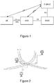
- Positioning in LTE is supported by the positioning architecture schematically illustrated in Figure 1 , with direct interactions between a UE and a location server, sometimes also referred to as an Evolved-Serving Mobile Location Centre (E-SMLC), via the LTE Positioning Protocol (LPP).
- E-SMLC Evolved-Serving Mobile Location Centre
- LTP LTE Positioning Protocol
- the E-SMLC is connected to the Mobility Management Entity (MME).
- MME Mobility Management Entity
- An SLs interface is defined between the E-SMLC and MME and the MME is connected over the S1 interface to the eNB.
- the OTDOA is a UE-assisted method, in which the UE measures the time of arrival (TOA) of specific positioning reference signals (PRS) from multiple cells (or eNBs), and computes the relative differences between each cell and a reference cell.
- TOA time of arrival
- PRS specific positioning reference signals
- RSTD reference signal time difference
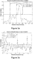
- FIG. 2 illustrates the multi-lateration in OTDOA when eNB1 is considered as the reference cell. For this case it is the measure of the relative difference between TOA of PRS from eNB3 and eNB1 (t3-t1) and the measure of the relative difference between TOA of PRS from eNB2 and eNB1 (t2-t1) that are relevant.
- Wireless channels are usually modelled as multipath channels, meaning that the receiving node receives several distorted and delayed copies of the transmitted signal through multiple reflections and diffraction, etc.
- the multi-path effect can be modelled by considering the following tapped delay link channel.
- ⁇ 0 is the time delay corresponding to the line-of-sight (LOS) tap, and scale it with the speed of light.
- TOA of the signal can be measured based on a reference signal that is known to the receiver.
- the transmitted signal is denoted "x(t)”
- the receiver is interested in computing time delay of the first channel tap ⁇ 0 , i.e., TOA of the LOS signal or the signal that arrives earliest if there is no LOS, since that translates to the distance between transmitter and receiver.
- the received signal is embedded in noise and interference, it is not always easy to determine the first channel tap if it is not strong enough, which is usually the case in indoor scenarios.
- the cross-correlation function R( ⁇ ) gives channel impulse response.
- the absolute value of R( ⁇ ) corresponds to the Power Delay Profile (PDP) of the channel.
- PDP Power Delay Profile
- the next step is to determine the first channel tap, which can be estimated by determining the first peak in R[ ⁇ ] that is above a certain threshold ⁇ .
- ⁇ ⁇ arg min R ⁇ max R ⁇ ⁇ .
- Finding the LOS component based on the cross-correlation as discussed above, is not an easy task for a UE.
- the UE needs to find a proper threshold in order to find the LOS component since the LOS tap is typically not the strongest tap. If the threshold is too low, the receiver can falsely detect noise as first channel tap and if the threshold is too high, the receiver may miss a weak LOS signal. Therefore, there is typically a trade-off between LOS detection and robustness to noise.
- a higher SINR can improve the robustness to detect an LOS peak, that is, a higher SINR can mitigate the TOA estimation error caused by a strong non-LOS (NLOS) signal component.
- NLOS non-LOS
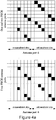
- Figures 3a and 3b show situations where a UE fails to estimate a proper TOA when using a threshold-based peak detection.
- the graphs show how the cross-correlation values depend on the distance.
- the threshold is in the figures illustrated by a horizontal solid line (max peak/2).
- the leftmost vertical line (exact time) indicates the exact time (corresponding to a distance in meters) of the peak corresponding to the TOA of the LOS signal
- the rightmost vertical line (estimated) indicates the estimated time of the peak corresponding to the TOA of the LOS signal.
- Figure 3b it is the opposite and the leftmost vertical line (estimated time) indicates the estimated time of the peak corresponding to the TOA of the LOS signal, and the rightmost vertical line (exact time) indicates the exact time of the peak corresponding to the TOA of the LOS signal.
- Figure 3a exemplifies a situation where a lower threshold value would have improved the TOA estimation considerably.
- Figure 3b exemplifies a situation where a higher threshold value would have improved the TOA estimation considerably.
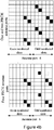
- FIG. 4a and Figure 4b illustrate the arrangement of the PRS assigned resources (black squares) for one resource block (RB) and for two different antenna port configurations using normal Cyclic Prefix (CP) and extended CP respectively.
- CP Cyclic Prefix
- PDSCH Physical Downlink Shared Channel
- Physical Downlink Control Channel (PDCCH) and CRSs are retained in the subframe, while PRSs are distributed in a "diagonal" way between CRSs.
- Alike CRS a cell-specific frequency shift is applied to the PRS pattern.
- the number of frequency shifts is given by Physical Cell Identity (PCI) modulo 6, for avoiding time-frequency PRS collisions in up to six neighbor cells.
- PCI modulo 6 Physical Cell Identity
- Using a PRS pattern with a frequency shift given by PCI modulo 6 results in a frequency reuse factor of six.
- the frequency reuse factor is the rate at which the same PRS frequency can be used in the network. It is denoted K (sometimes 1/K) where K is the number of cells which cannot use the same frequencies for PRS transmission.
- K sometimes 1/K
- TP Transmission Point
- N ID PRS is a value of a PRS identity, hereinafter referred to as prsID, which is a special identity of the PRS sequence as such, uncoupled from the cell (with a certain PCI corresponding to the N ID cell ) that transmits the PRS sequence.
- prsID a PRS identity
- the range of the prsID values or N ID PRS is 0 to 4095.
- the new PRS sequence generation in Rel.14 is introduced to decouple the PRS from the PCI by introducing the prsID N ID PRS .
- the IE OTDOA-ProvideAssistanceData is used by the location server to provide assistance data to enable UE assisted downlink OTDOA.
- One of the OTDOA Assistance Data Elements is the IE PRS-Info which provides the information related to the configuration of PRS in a cell. PRS-Info is according to the proposal extended as follows (new parts in bold):
- OTDOA-ReferenceCelllnfo Another of the OTDOA Assistance Data Elements is the IE OTDOA-ReferenceCelllnfo which is used by the location server to provide assistance data related to reference cell information.
- the OTDOA-referenceCelllnfo is extended with the field tpld which specifies the identity of a TP associated with a cell identified by a PCI (physCellld).
- the tpld field together with the physCellld and/or the prsID may be used to identify the TP when the same PCI is shared by multiple transmission points.
- the OTDOA Assistance Data Elements also comprises IE OTDOA-NeighbourCellInfoList used by the location server to provide neighbour cell information.
- the OTDOA-neighboringCelllnfoEelement is also extended with the tpld field as shown below:
- An object of embodiments is to alleviate or at least reduce one or more of the above-mentioned problems, and to provide a solution allowing an adaptive frequency reuse factor for PRS. This object, and others, is achieved by methods and apparatus according to embodiments herein.
- One advantage of embodiments is that they allow a more efficient resource usage for PRS by providing a flexibility of the PRS frequency reuse.
- nodes, interfaces, circuits, and devices are omitted so as not obscure the description with unnecessary detail.
- the functions described may be implemented in one or in several nodes. Some or all of the functions described may be implemented using hardware circuitry, such as analog and/or discrete logic gates interconnected to perform a specialized function, or ASICs. Likewise, some or all of the functions may be implemented using software programs and data in conjunction with one or more digital microprocessors or general-purpose computers. Where nodes that communicate using the air interface are described, it will be appreciated that those nodes also have suitable radio communications circuitry.
- the technology may be embodied entirely within any form of computer-readable memory, including non-transitory embodiments such as solid-state memory, magnetic disk, or optical disk containing an appropriate set of computer instructions that would cause a processor to carry out the techniques described herein.
- Hardware implementations of the present invention may include or encompass, without limitation, digital signal processor (DSP) hardware, a reduced instruction set processor, hardware (e.g., digital or analog) circuitry including but not limited to application specific integrated circuit(s) (ASIC) and/or field programmable gate array(s) (FPGA(s)), and where appropriate state machines capable of performing such functions.
- DSP digital signal processor
- ASIC application specific integrated circuit
- FPGA field programmable gate array
- a computer is generally understood to comprise one or more processors or one or more controllers, and the terms computer, processor, and controller may be employed interchangeably.
- the functions may be provided by a single dedicated computer or processor or controller, by a single shared computer or processor or controller, or by a plurality of individual computers or processors or controllers, some of which may be shared or distributed.
- processor or “controller” also refers to other hardware capable of performing such functions and/or executing software, such as the example hardware recited above.
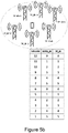
- the UE is within coverage of only three TPs, and is thus able to calculate the RSTDs for those three TPs.
- the unused PRS resources are illustrated in the table in Figure 5a where the resource allocation for each TP Identity (TP_ID) within a PRS resource block for one OFDM symbol is shown.
- TP_ID TP Identity
- a sparse deployment scenario is for example an indoor environment with only a few deployed nodes, or a deployment in a rural area.
- FIG. 5b Another denser deployment scenario is illustrated in Figure 5b .
- the table in the figure shows the PRS resource allocation for each TP-ID in one PRS resource block.
- One example of a wireless communication systems configured for positioning and using positioning reference signals for positioning measurements other than the 3GPP LTE system may be an NB-loT system.
- the PRS used in NB-loT is referred to as a Narrowband PRS (NPRS).
- NPRS Narrowband PRS
- the use of a fixed PRS frequency reuse factor in all deployment scenarios may be suboptimal with regards to the PRS resource usage.
- This problem is addressed by a solution in which the PRS frequency reuse factor may vary related to a default frequency reuse factor, so that e.g. all available PRS resources may be used in a scenario as the one illustrated in Figure 5a .
- a better PRS utilization can be obtained in a sparse deployment and in certain indoor deployments. This is achieved by configuring multiple prslDs for each TP. With more prslDs for a TP, the number of PRS resources per TP increases, which may improve the SINR and thus the positioning accuracy.
- Figure 6 illustrates a PRS resource allocation in a sparse deployment scenario according to embodiments of the invention.
- Figure 6 shows how the number of PRS resources per TP is doubled in comparison with Figure 5a , which means that the SINR level increases by 3dB at the UE for the involved TPs.
- the doubling of the PRS per TP correspond to a frequency reuse factor reduction from 6 to 3, as the frequencies are reduced in every third cell. This does not cause any interference problem as the UE can't hear more than three cells anyway.
- embodiments of the invention can be implemented by introducing new signaling elements in LPP, or by using the existing LPP signaling as described in the background section.
- PRSs are thus generated based on multiple prslDs for one TP and transmitted to the UE. This provides a possibility to change the frequency reuse and exploit more PRS resource to increase the SINR and hence positioning accuracy in deployment scenarios where few cells are hearable to the UE.
- the UE When a UE receives several PRS's from a TP which is generated using multiple prsIDs, the UE combines the estimated channel for each individual PRS. This may be implemented through the cross-correlation procedure described previously. Parts of the procedure are repeated hereinafter.
- the known transmitted signal X k corresponds to the k:th transmitted individual PRS generated by a single prsID for one TP.
- the cross-correlation function (or channel) is therefore calculated or derived for each individual PRS received at the UE.
- the combination of the cross-correlations will reduce the noise power in R final . This will improve the Signal to Noise Ratio (SNR) at the UE and increase the TOA estimation accuracy.
- SNR Signal to Noise Ratio
- Non-coherent combining can for example be beneficial if different precoders are used for each individual PRS.
- the cross-correlation procedure described above is a non-limiting example of a low-complexity implementation.
- R final there are many alternative procedures for how to calculate R final , such as using a weighted average of R k , or a sum squared combination of R k .
- the UE method for processing the transmitted signal X k is not limited to the time-based procedure described above, but may instead be performed by frequency-domain processing for example.
- R final [ ⁇ ] is used to calculate the TOA, as described in the background section. Based on the set of estimated TOAs, the RSTDs can be formed, and the location of the UE can be estimated.
- the location server may be an E-SMLC.
- the UE may be served by a cell controlled by an eNodeB which is a master node for a number of TPs or eNodeBs serving one cell each.
- the information transmitted between the location server and the UE is transmitted over the wireless link to the UE with the help from the TP/eNodeB of the UE's serving cell.
- the location server may optionally receive a capability indication from the UE (via the UEs serving TP or eNodeB) indicating whether or not the UE can support multiple prsIDs, i.e. both receive them and process them.
- the capability indication is used by the location server to determine whether a frequency reuse factor other than the default frequency reuse factor may be selected for the PRS configuration of this UE, as described hereinafter. If the UE lacks the capability to handle multiple PRS-IDs and thereby multiple PRS for one TP when estimating TOA, it is no use to adapt the frequency reuse factor for a better PRS utilization. However, if the location server gets an indication that the UE has the capability to handle multiple PRS-IDs and thereby multiple PRS for one TP when estimating TOA, the frequency reuse factor may be adapted as described below.
- the frequency reuse factor to use may be determined or selected dependent on the scenario, and is a trade-off between hearability and robustness to interference.
- a lower frequency reuse factor should be used in order to increase the hearability for each TP. This would increase the interference for TPs transmitting in the same time-frequency resources.
- any interference from TPs with same time-frequency allocation may be neglectable.
- the location server may be the location server that determines or selects the frequency reuse factor.
- it may be another network node, such as an Operation and Maintenance node, that determines the frequency reuse factor and forwards it to the location server or to the eNodeB.
- the selection of the frequency reuse factor may be based on one or more of the following properties:
- the location server selects or determines the prslDs based on the frequency reuse factor.
- the set of chosen prslDs needs to be selected wisely in order to ensure that none of the chosen prslDs has the same frequency shift, since that would imply that two individual PRS in the group of TPs use the same time-frequency resources.
- a TP should be assigned with two prslDs (corresponding to a frequency reuse factor of 3), and the first prsID is 0, the second prsID should not be any of the following set of prslDs ⁇ 0,6,12,18, 24,..etc. ⁇ .
- ⁇ shift N ID PRS mod 6 for determining the frequency shift, this implies that one could assign up to six different prslDs per TP, and still ensure time-frequency orthogonality of the corresponding PRSs.
- the prsID should be chosen in a way that ensures that the interference towards other TPs is minimized.
- two TPs should be sufficiently geographically separated if selecting same prsID, or the same frequency shift. In the latter case, with two different prsIDs, but the same frequency shift, the interference between the two individual PRSs is suppressed by the processing gain of the PRS sequence, and the individual PRSs can be reused geographically closer compared to the same prsID.
- the UE may then receive a PRS configuration from the location server comprising multiple prslDs.
- the signaling of the multiple prslDs in the PRS configuration may be performed using for example LPP.
- Support for multiple prsID may be achieved using the existing LPP specification. Since the OTDOA-NeighbourCelllnfoElement is a sequence of elements containing PRS info, one could use two or more elements with a same TP-ID but with different prslDs in the PRS-Info element.
- This embodiment could be easily implemented using the existing LPP protocol.
- multiple prslDs may be included in the prslnfo element as illustrated in the signaling specification below.
- the prslD-r14 is thus amended or extended to support a list of prslDs. This embodiment would make the multiple prsID report more efficient than the previous embodiment, as the signaling would be more compact with less signaling overhead.
- the location server thus transmits a multiple prsID information element to the UE in the PRS configuration.
- the eNodeB subsequently generates PRS according to the PRS configuration.
- the multiple prsID information element may optionally comprise an indication that the location server intends to send multiple prslDs per TP. This could save processing overhead at the UE since the UE may avoid searching for matches of TP-IDs when no multiple-prslDs are configured.
- information signaled to the UE may comprise information indicating what procedure to use when estimating the channel or more generally when determining the RSTD values. The information signaled to the UE may e.g.
- the UE should preferably combine the estimated channel for each individual PRS non-coherently.
- the UE may detect that two OTDOA-NeighbourCelllnfoElement elements include the same TP-ID.
- the combined channel is then used for estimating the RSTD for TP 0. So, for each TP, the UE estimates a TOA based on the estimated R_final described above, and then forms the RSTDs. The UE thus measures the RSTD based on the received PRS configuration.
- the UE reports the RSTD values via the LPP signaling to the location server.
- the location server thus receives a report comprising the RSTD measurement results or the RSTD values from the UE.
- the report optionally comprises whether or not a frequency reuse other than the default was required, i.e. whether multiple prslDs was required, for determining the RSTD.
- the UE may only include a subset of the estimated cross correlations R k [ ⁇ ] in the sum.
- the UE may thus assess whether or not the same RSTD accuracy could be provided by processing only one of the individual PRS instead of all or a subset of them.
- the number of individual PRS needed to achieve an accurate RSTD may be signaled by the UE to the location server.
- Figure 7 is a flowchart illustrating one embodiment of a method performed by a network node of a wireless communication network, for receiving a reference signal time difference, RSTD, value from a wireless device.
- the network node may be a location server, such as an E-SMLC, or an eNodeB or TP of an LTE network, and the wireless device may be a UE.
- the method steps that are within boxes with dashed lines are optional steps. These optional steps may not always be performed or may in some embodiments be performed by another network node.
- the method may comprise:
- the method may further comprise transmitting to the wireless device an indication of a procedure to use for determining the RSTD value.
- the method may further comprise receiving information from the wireless device indicating whether all or a subset of PRSs generated using the plurality of PRS identities for the TP was used for determining the received RSTD value, as indicated in the above section "Example embodiment of a method in a location server and a UE", under section F.
- the network node may be an eNodeB, or a base station controlling the TP for which the RSTD value is received, that performs the steps 730 and 740 described above.
- the method may further comprise scheduling the TP to transmit PRSs to the wireless device, where the PRSs are generated using the plurality of PRS identities for the TP in accordance with the transmitted configuration.
- Figure 8 is a flowchart illustrating one embodiment of a method performed by a wireless device for reporting a reference signal time difference, RSTD, value to a network node of a wireless communication network.
- the network node may be a location server, such as an E-SMLC, or an eNodeB or TP of an LTE network, and the wireless device may be a UE.
- the method steps that are within boxes with dashed lines are optional steps. These optional steps may not always be performed.
- the method may comprise:
- the method may further comprise receiving an indication of a procedure to use for determining the RSTD value.
- the method may further comprise transmitting information to the network node indicating a capability to handle a plurality of PRS identities for one TP.
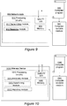
- An embodiment of the network node 900 for a wireless communication network configured to receive a reference signal time difference, RSTD, value from a wireless device is schematically illustrated in the block diagram in Figure 9 .
- the network node is further configured to transmit a configuration of positioning reference signals, PRSs, to the wireless device, the configuration indicating a plurality of PRS identities for respective transmission points, TPs, of the wireless communication network, and receive an RSTD value for a TP from the wireless device determined based on the configuration of PRSs.
- PRSs positioning reference signals
- the network node may be further configured to determine a location of the wireless device based on the received RSTD value.
- the network node may be further configured to obtain a first frequency reuse factor for PRSs that is lower than a default second frequency reuse factor, and determine the plurality of PRS identities for the respective TPs based on the obtained first frequency reuse factor, wherein the determined plurality of PRS identities are indicated in the transmitted configuration.
- the network node may be configured to determine the plurality of PRS identities by being configured to select the plurality of PRS identities such that PRSs generated using the plurality of PRS identities are time-frequency orthogonal.
- the network node may be configured to obtain the first frequency reuse factor by being configured to receive the frequency reuse factor from another network node.
- the network node may be configured to obtain the first frequency reuse factor by being configured to determine the frequency reuse factor based on at least one of: a geographic deployment of the TPs; radio characteristics of the TPs; historical information related to RSTD reports from the wireless device for the respective TPs; a capability of handling the plurality of PRS identities associated with the wireless device; a coverage class of the wireless device.
- the network node may be a base station configured to control the TP for which the RSTD value is received, which may be further configured to schedule the TP to transmit PRSs to the wireless device, where the PRSs are generated using the plurality of PRS identities for the TP in accordance with the transmitted configuration.
- the network node may be further configured to transmit information to the wireless device informing that the configuration will indicate a plurality of PRS identities for respective TPs, before transmitting the configuration of PRSs.
- the network node may be further configured to transmit to the wireless device an indication of a procedure to use for determining the RSTD value.
- the network node may be further configured to receive information from the wireless device indicating whether all or a subset of PRSs generated using the plurality of PRS identities for the TP was used for determining the received RSTD value.
- the network node 900 may comprise at least one processing circuitry 910 and optionally also a memory 930.
- the memory 930 may be placed in some other node or unit or at least separately from the network node.
- the network node may also comprise one or more input/output (I/O) units 920 configured to communicate with a wireless device or another network node.
- the input/output (I/O) unit 920 may in embodiments comprise a transceiver connected to one or more antennas over antenna ports for wireless communication with wireless devices in the network, and/or an interface circuitry adapted for communication with other network nodes over various interfaces.
- the memory 930 may contain instructions executable by said at least one processing circuitry 910, whereby the network node may be configured to transmit a configuration of positioning reference signals, PRSs, to the wireless device, the configuration indicating a plurality of PRS identities for respective transmission points, TPs, of the wireless communication network, and receive an RSTD value for a TP from the wireless device determined based on the configuration of PRSs.
- PRSs positioning reference signals
- the memory 930 contains instructions executable by the processing circuitry 910 whereby the network node is configured to perform any of the methods previously described herein with reference to Figure 7 .
- the network node may comprise a transmitting module 911, and a receiving module 912, adapted to respectively transmit a configuration of positioning reference signals, PRSs, to the wireless device, the configuration indicating a plurality of PRS identities for respective transmission points, TPs, of the wireless communication network, and receive an RSTD value for a TP from the wireless device determined based on the configuration of PRSs.
- PRSs positioning reference signals
- the network node may contain further modules adapted to perform any of the methods previously described herein.
- modules described above are functional units which may be implemented in hardware, software, firmware or any combination thereof.
- the modules are implemented as a computer program running on the at least one processing circuitry 910.
- the network node may comprise a Central Processing Unit (CPU) which may be a single unit or a plurality of units.
- the network node may comprise at least one computer program product (CPP) with a computer readable medium 941, e.g. in the form of a non-volatile memory, e.g. an EEPROM (Electrically Erasable Programmable Read-Only Memory), a flash memory or a disk drive.
- the CPP may comprise a computer program 940 stored on the computer readable medium 941, which comprises code means which when run on the CPU of the network node causes the network node to perform the methods described earlier in conjunction with Figure 7 . In other words, when said code means are run on the CPU, they correspond to the at least one processing circuitry 910 of the network node in Figure 9 .
- the wireless device 1000 is configured to report a reference signal time difference, RSTD, value to a network node of a wireless communication network, the wireless device being further configured to receive a configuration of positioning reference signals, PRSs, from the network node, the configuration indicating a plurality of PRS identities for respective transmission points, TPs, of the wireless communication network, determine an RSTD value for a TP based on the received configuration, and report the determined RSTD value for the TP to the network node.
- RSTD reference signal time difference
- the wireless device may be further configured to receive PRSs generated using the plurality of PRS identities from the TP in accordance with the received configuration, wherein the RSTD value for the TP is determined based on the received PRSs.
- the wireless device may be further configured to determine the RSTD value for the TP using all or a subset of the received PRSs.
- the wireless device may be further configured to determine the RSTD value for the TP by being configured to combine channel estimates for all or a subset of the received PRSs and determine the RSTD value based on the combined channel estimates.
- the wireless device may be further configured to transmit information to the network node indicating whether all or a subset of the received PRSs were used for determining the RSTD value.
- the wireless device may be further configured to receive information from the network node informing that the configuration will indicate a plurality of PRS identities for respective TPs, and to use the information for receiving the configuration.
- the wireless device may be further configured to receive an indication of a procedure to use for determining the RSTD value.
- the wireless device may be further configured to transmit information to the network node indicating a capability to handle a plurality of PRS identities for one TP.
- the wireless device 1000 may comprise at least one processing circuitry 1010 and optionally also a memory 1030.
- the memory 1030 may be placed in some other node or unit or at least separately from the wireless device 1000.
- the wireless device 1000 may also comprise one or more input/output (I/O) units 1020 configured to communicate with a network node such as an eNodeB.
- the input/output (I/O) unit 1020 may in embodiments comprise a transceiver connected to one or more antennas over antenna ports for wireless communication with network nodes in the network.
- the memory 1030 may contain instructions executable by said at least one processing circuitry 1010, whereby the wireless device 1000 may be configured to receive a configuration of positioning reference signals, PRSs, from the network node, the configuration indicating a plurality of PRS identities for respective transmission points, TPs, of the wireless communication network, determine an RSTD value for a TP based on the received configuration, and report the determined RSTD value for the TP to the network node.
- PRSs positioning reference signals
- the memory 1030 contains instructions executable by the processing circuitry 1010 whereby the wireless device is configured to perform any of the methods previously described herein with reference to Figure 8 .
- the wireless device 1000 may comprise a receiving module 1011, a determining module 1012, and a reporting module 1013, adapted to respectively receive a configuration of positioning reference signals, PRSs, from the network node, the configuration indicating a plurality of PRS identities for respective transmission points, TPs, of the wireless communication network, determine an RSTD value for a TP based on the received configuration, and report the determined RSTD value for the TP to the network node.
- PRSs positioning reference signals
- the wireless device 1000 may contain further modules adapted to perform any of the methods previously described herein.
- modules described above are functional units which may be implemented in hardware, software, firmware or any combination thereof.
- the modules are implemented as a computer program running on the at least one processing circuitry 1010.
- the wireless device 1000 may comprise a Central Processing Unit (CPU) which may be a single unit or a plurality of units. Furthermore, the wireless device 1000 may comprise at least one computer program product (CPP) with a computer readable medium 1041, e.g. in the form of a non-volatile memory, e.g. an EEPROM (Electrically Erasable Programmable Read-Only Memory), a flash memory or a disk drive.
- the CPP may comprise a computer program 1040 stored on the computer readable medium 1041, which comprises code means which when run on the CPU of the wireless device 1000 causes the wireless device 1000 to perform the methods described earlier in conjunction with Figure 8 . In other words, when said code means are run on the CPU, they correspond to the at least one processing circuitry 1010 of the wireless device 1000 in Figure 10 .
Landscapes
- Engineering & Computer Science (AREA)
- Physics & Mathematics (AREA)
- General Physics & Mathematics (AREA)
- Radar, Positioning & Navigation (AREA)
- Remote Sensing (AREA)
- Computer Networks & Wireless Communication (AREA)
- Signal Processing (AREA)
- Mobile Radio Communication Systems (AREA)
Claims (15)
- Verfahren, das von einem Netzwerkknoten eines drahtlosen Kommunikationsnetzwerks durchgeführt wird, zum Empfangen eines Wertes einer Referenzsignalzeitdifferenz, RSTD, von einer drahtlosen Vorrichtung, wobei das Verfahren umfasst:- Senden (730) einer Konfiguration von Positionsbestimmungsreferenzsignalen, PRSs, an die drahtlose Vorrichtung, wobei die Konfiguration eine Mehrzahl von PRS-Kennungen für einen Übertragungspunkt, TP, des drahtlosen Kommunikationsnetzwerks angibt, und- Empfangen (740) eines RSTD-Wertes für den TP von der drahtlosen Vorrichtung, der basierend auf der Konfiguration von PRSs bestimmt wird.
- Verfahren, das von einer drahtlosen Vorrichtung durchgeführt wird, zum Melden eines Wertes einer Referenzsignalzeitdifferenz, RSTD, an einen Netzwerkknoten eines drahtlosen Kommunikationsnetzwerks, wobei das Verfahren umfasst:- Empfangen (810) einer Konfiguration von Positionsbestimmungsreferenzsignalen, PRSs, vom Netzwerkknoten, wobei die Konfiguration eine Mehrzahl von PRS-Kennungen für einen Übertragungspunkt, TP, des drahtlosen Kommunikationsnetzwerks angibt, und- Bestimmen (820) eines RSTD-Wertes für den TP basierend auf der empfangenen Konfiguration und- Melden (830) des bestimmten RSTD-Wertes für den TP an den Netzwerkknoten.
- Netzwerkknoten (900) für ein drahtloses Kommunikationsnetzwerk, der zum Empfangen eines Wertes einer Referenzsignalzeitdifferenz, RSDT, von einer drahtlosen Vorrichtung konfiguriert ist, wobei der Netzwerkknoten ferner konfiguriert ist zum:- Senden einer Konfiguration von Positionsbestimmungsreferenzsignalen, PRSs, an die drahtlose Vorrichtung, wobei die Konfiguration eine Mehrzahl von PRS-Kennungen für einen Übertragungspunkt, TP, des drahtlosen Kommunikationsnetzwerks angibt, und- Empfangen eines RSTD-Wertes für den TP von der drahtlosen Vorrichtung, der basierend auf der Konfiguration von PRSs bestimmt wurde.
- Netzwerkknoten nach Anspruch 3, ferner konfiguriert zum:- Bestimmen eines Standorts der drahtlosen Vorrichtung basierend auf dem empfangenen RSTD-Wert.
- Netzwerkknoten nach einem der Ansprüche 3 bis 4, ferner konfiguriert zum:- Erhalten eines ersten Frequenzwiederverwendungsfaktors für PRSs, der niedriger als ein standardmäßiger zweiter Frequenzwiederverwendungsfaktor ist,- Bestimmen der Mehrzahl von PRS-Kennungen für den TP basierend auf dem erhaltenen ersten Frequenzwiederverwendungsfaktor, wobei die bestimmte Mehrzahl von PRS-Kennungen in der gesendeten Konfiguration angegeben wird.
- Netzwerkknoten nach Anspruch 5, konfiguriert zum Bestimmen der Mehrzahl von PRS-Kennungen, indem er konfiguriert ist zum:- Auswählen der Mehrzahl von PRS-Kennungen derart, dass die PRSs, die unter Verwendung der Mehrzahl von PRS-Kennungen erzeugt werden, Zeit-Frequenzorthogonal sind.
- Netzwerkknoten nach einem der Ansprüche 5 bis 6, konfiguriert zum Erhalten des ersten Frequenzwiederverwendungsfaktors, indem er zu einem von Folgendem konfiguriert ist:- Empfangen des Frequenzwiederverwendungsfaktors von einem anderen Netzwerkknoten;- Bestimmen des Frequenzwiederverwendungsfaktors basierend auf mindestens einem von: einer geografischen Bereitstellung des TPs; Funkcharakteristiken des TPs; historischen Informationen in Bezug auf RSTD-Meldungen von der drahtlosen Vorrichtung für den TP; einer Fähigkeit zum Handhaben der Mehrzahl von PRS-Kennungen, die mit der drahtlosen Vorrichtung assoziiert ist; einer Versorgungsklasse der drahtlosen Vorrichtung.
- Netzwerkknoten nach Anspruch 3, wobei der Netzwerkknoten eine Basisstation ist, die zum Steuern des TPs konfiguriert ist, für welchen der RSTD-Wert empfangen wird, und ferner konfiguriert ist zum:- Disponieren des TPs zum Senden von PRSs an die drahtlose Vorrichtung, wobei die PRSs unter Verwendung der Mehrzahl von PRS-Kennungen für den TP gemäß der gesendeten Konfiguration erzeugt werden.
- Netzwerkknoten nach einem der Ansprüche 3 bis 8, ferner konfiguriert zum:- Senden von Informationen an die drahtlose Vorrichtung, die informieren, dass die Konfiguration eine Mehrzahl von PRS-Kennungen für den TP angibt, vor dem Senden der Konfiguration von PRSs.
- Netzwerkknoten nach einem der Ansprüche 3 bis 9, ferner konfiguriert zum:- Empfangen von Informationen von der drahtlosen Vorrichtung, die angeben, ob die Gesamtheit oder ein Teilsatz von PRSs, die unter Verwendung der Mehrzahl von PRS-Kennungen für den TP erzeugt werden, zum Bestimmen des empfangenen RSTD-Wertes verwendet wurde.
- Drahtlose Vorrichtung (1000), die zum Melden eines Wertes einer Referenzsignalzeitdifferenz, RSTD, an einen Funknetzwerkknoten eines drahtlosen Kommunikationsnetzwerks konfiguriert ist, wobei die drahtlose Vorrichtung ferner konfiguriert ist zum:- Empfangen einer Konfiguration von Positionsbestimmungsreferenzsignalen, PRSs, vom Netzwerkknoten, wobei die Konfiguration eine Mehrzahl von PRS-Kennungen für einen Übertragungspunkt, TP, des drahtlosen Kommunikationsnetzwerks angibt, und- Bestimmen eines RSTD-Wertes für den TP basierend auf der empfangenen Konfiguration und- Melden des bestimmten RSTD-Wertes für den TP an den Netzwerkknoten.
- Drahtlose Vorrichtung nach Anspruch 11, ferner konfiguriert zum:- Empfangen von PRSs, die unter Verwendung der Mehrzahl von PRS erzeugt wurden, vom TP gemäß der empfangenen Konfiguration, wobei der RSTD-Wert für den TP basierend auf den empfangen PRSs bestimmt wird.
- Drahtlose Vorrichtung nach Anspruch 12, ferner konfiguriert zum Bestimmen des RSTD-Wertes für den TP unter Verwendung der Gesamtheit oder eines Teilsatzes der empfangenen PRSs.
- Drahtlose Vorrichtung nach Anspruch 12, ferner konfiguriert zum Bestimmen des RSTD-Wertes für den TP, indem sie zum Kombinieren von Kanalschätzungen für die Gesamtheit oder einen Teilsatz der empfangenen PRSs und Bestimmen des RSTD-Wertes basierend auf den kombinierten Kanalschätzungen konfiguriert ist.
- Drahtlose Vorrichtung nach einem der Ansprüche 13 bis 14, ferner konfiguriert zum:- Senden von Informationen, die angeben, ob die Gesamtheit oder ein Teilsatz der empfangenen PRSs zum Bestimmen des RSTD-Wertes verwendet wurde, an den Netzwerkknoten.
Applications Claiming Priority (2)
| Application Number | Priority Date | Filing Date | Title |
|---|---|---|---|
| US201662432757P | 2016-12-12 | 2016-12-12 | |
| PCT/SE2017/051194 WO2018111173A1 (en) | 2016-12-12 | 2017-11-30 | Methods and apparatus for reporting rstd values |
Publications (2)
| Publication Number | Publication Date |
|---|---|
| EP3552443A1 EP3552443A1 (de) | 2019-10-16 |
| EP3552443B1 true EP3552443B1 (de) | 2021-10-27 |
Family
ID=60782311
Family Applications (1)
| Application Number | Title | Priority Date | Filing Date |
|---|---|---|---|
| EP17818320.8A Active EP3552443B1 (de) | 2016-12-12 | 2017-11-30 | Verfahren und vorrichtung zur berichterstattung von rstd-werten |
Country Status (3)
| Country | Link |
|---|---|
| US (1) | US10656241B2 (de) |
| EP (1) | EP3552443B1 (de) |
| WO (1) | WO2018111173A1 (de) |
Families Citing this family (13)
| Publication number | Priority date | Publication date | Assignee | Title |
|---|---|---|---|---|
| EP3621255A1 (de) * | 2018-09-06 | 2020-03-11 | FRAUNHOFER-GESELLSCHAFT zur Förderung der angewandten Forschung e.V. | Gateway, benutzerendgerät, verfahren zum betrieb davon und drahtloskommunikationsnetzwerk |
| EP3858002A1 (de) * | 2018-09-28 | 2021-08-04 | Telefonaktiebolaget LM Ericsson (publ) | Neues prs-design durch erweiterung des basissignals |
| CN113167850B (zh) * | 2018-10-05 | 2024-08-23 | 瑞典爱立信有限公司 | 基于波束的定位测量和测量报告 |
| EP3911052B1 (de) * | 2019-02-15 | 2023-08-30 | LG Electronics Inc. | Lokalisierung in einem drahltlosen kommunicaktionsystem |
| EP3949572B1 (de) * | 2019-03-26 | 2025-07-16 | Nokia Technologies Oy | Messungen für auf abruf arbeitende referenzsignalübertragung |
| US11483794B2 (en) * | 2019-08-23 | 2022-10-25 | Qualcomm Incorporated | Ranging signal transmission in unlicensed band |
| US12120544B2 (en) | 2020-05-15 | 2024-10-15 | Qualcomm Incorporated | Reducing the overhead of reporting measurements and transmission-reception point (TRP) identifiers in positioning state information (PSI) |
| WO2022016468A1 (zh) * | 2020-07-23 | 2022-01-27 | 北京小米移动软件有限公司 | 定位测量方法、定位测量装置及存储介质 |
| CN116137952B (zh) * | 2020-07-31 | 2025-11-18 | 瑞典爱立信有限公司 | 用于toa估计的cir峰值阈值控制 |
| US12520269B2 (en) | 2020-10-26 | 2026-01-06 | Nokia Technologies Oy | Positioning based on multiple measurement reports |
| WO2023073511A1 (en) * | 2021-10-26 | 2023-05-04 | Guangdong Oppo Mobile Telecommunications Corp., Ltd. | Methods and apparatus of priority of processing downlink positioning reference signal |
| WO2023072382A1 (en) * | 2021-10-27 | 2023-05-04 | Nokia Technologies Oy | User device orientation |
| GB202304574D0 (en) * | 2023-03-29 | 2023-05-10 | Nokia Technologies Oy | Position determination in a communication system |
Family Cites Families (6)
| Publication number | Priority date | Publication date | Assignee | Title |
|---|---|---|---|---|
| EP2394461A4 (de) * | 2009-02-05 | 2016-06-08 | Apple Inc | Verfahren und system zur standortbestimmung von benutzergeräten in einem drahtlosen übertragungssystem |
| US10028207B2 (en) * | 2014-01-16 | 2018-07-17 | Industry-University Cooperation Foundation Banyard University | Method for transmitting and receiving downlink channel for MTC terminal, and apparatus therefor |
| US9774429B2 (en) * | 2014-03-12 | 2017-09-26 | Qualcomm Incorporated | Techniques for transmitting positioning reference signals in an unlicensed radio frequency spectrum band |
| EP3146773A1 (de) | 2014-05-20 | 2017-03-29 | Telefonaktiebolaget LM Ericsson (publ) | Verfahren und vorrichtungen zur positionierung in netzwerkzellen mit mehreren übertragungspunkten |
| CN107925496B (zh) * | 2015-08-25 | 2019-09-17 | Lg 电子株式会社 | 在无线通信系统中测量用于定位的参考信号的方法及设备 |
| US10469226B2 (en) * | 2015-10-05 | 2019-11-05 | Iucf-Hyu (Industry-University Cooperation Foundation Hanyang University) | Method for transmitting and receiving positioning reference signal in wireless communication system and device therefor |
-
2017
- 2017-11-30 EP EP17818320.8A patent/EP3552443B1/de active Active
- 2017-11-30 WO PCT/SE2017/051194 patent/WO2018111173A1/en not_active Ceased
- 2017-11-30 US US16/347,854 patent/US10656241B2/en active Active
Also Published As
| Publication number | Publication date |
|---|---|
| WO2018111173A1 (en) | 2018-06-21 |
| US10656241B2 (en) | 2020-05-19 |
| EP3552443A1 (de) | 2019-10-16 |
| US20190353748A1 (en) | 2019-11-21 |
Similar Documents
| Publication | Publication Date | Title |
|---|---|---|
| EP3552443B1 (de) | Verfahren und vorrichtung zur berichterstattung von rstd-werten | |
| US12047904B2 (en) | Positioning reference signal staggering configuration | |
| US11546103B2 (en) | Physical layer aspects of round-trip time and observed time difference of arrival based positioning | |
| EP3668205B1 (de) | Verfahren und vorrichtung zur positions- und messungsmeldung | |
| KR102085001B1 (ko) | 포지셔닝 레퍼런스 시그널의 전송 | |
| US8725167B2 (en) | Methods of providing cell grouping for positioning and related networks and devices | |
| EP3295731B1 (de) | Vorrichtungen und verfahren darin für positionsmessungen | |
| EP3335483B1 (de) | Verfahren und vorrichtungen zur positionierung auf basis des feedbacks von signalkorrelationsfunktionseigenschaften | |
| KR101592796B1 (ko) | Otdoa 측정들의 성능을 향상시키기 위한 간섭 제어, sinr 최적화 및 시그널링 강화 | |
| EP3120491B1 (de) | Referenzsignalverbesserung für gemeinsam genutzte zelle | |
| US20210341562A1 (en) | Beam based positioning measurements and measurement reporting | |
| EP3750360A1 (de) | Übertragung von bandbreitenabhängigem positionsreferenzsignal (prs) zur positionsbestimmung durch observed time difference of arrival (otdoa) in schmalbandigem internet der dinge (nb-iot) | |
| CN112913293A (zh) | 对用于往返时间估计的射频前端群延迟的处理 | |
| US20110176440A1 (en) | Restrictions on autonomous muting to enable time difference of arrival measurements | |
| CN113728692A (zh) | 用于新无线电定位的波束组报告的系统和方法 | |
| US20250294317A1 (en) | Information transmission method and apparatus, and carrier phase positioning method and apparatus | |
| US12108356B2 (en) | Wireless device, network node and methods performed therein for time of arrival estimation | |
| KR20240169608A (ko) | 지상 무선 네트워크에서의 캐리어 위상 기반 포지셔닝 |
Legal Events
| Date | Code | Title | Description |
|---|---|---|---|
| STAA | Information on the status of an ep patent application or granted ep patent |
Free format text: STATUS: UNKNOWN |
|
| STAA | Information on the status of an ep patent application or granted ep patent |
Free format text: STATUS: THE INTERNATIONAL PUBLICATION HAS BEEN MADE |
|
| PUAI | Public reference made under article 153(3) epc to a published international application that has entered the european phase |
Free format text: ORIGINAL CODE: 0009012 |
|
| STAA | Information on the status of an ep patent application or granted ep patent |
Free format text: STATUS: REQUEST FOR EXAMINATION WAS MADE |
|
| 17P | Request for examination filed |
Effective date: 20190506 |
|
| AK | Designated contracting states |
Kind code of ref document: A1 Designated state(s): AL AT BE BG CH CY CZ DE DK EE ES FI FR GB GR HR HU IE IS IT LI LT LU LV MC MK MT NL NO PL PT RO RS SE SI SK SM TR |
|
| AX | Request for extension of the european patent |
Extension state: BA ME |
|
| DAV | Request for validation of the european patent (deleted) | ||
| DAX | Request for extension of the european patent (deleted) | ||
| GRAP | Despatch of communication of intention to grant a patent |
Free format text: ORIGINAL CODE: EPIDOSNIGR1 |
|
| STAA | Information on the status of an ep patent application or granted ep patent |
Free format text: STATUS: GRANT OF PATENT IS INTENDED |
|
| RIC1 | Information provided on ipc code assigned before grant |
Ipc: G01S 5/10 20060101ALI20210421BHEP Ipc: G01S 5/02 20100101ALI20210421BHEP Ipc: H04W 24/10 20090101ALI20210421BHEP Ipc: H04W 64/00 20090101AFI20210421BHEP |
|
| INTG | Intention to grant announced |
Effective date: 20210514 |
|
| GRAS | Grant fee paid |
Free format text: ORIGINAL CODE: EPIDOSNIGR3 |
|
| GRAA | (expected) grant |
Free format text: ORIGINAL CODE: 0009210 |
|
| STAA | Information on the status of an ep patent application or granted ep patent |
Free format text: STATUS: THE PATENT HAS BEEN GRANTED |
|
| AK | Designated contracting states |
Kind code of ref document: B1 Designated state(s): AL AT BE BG CH CY CZ DE DK EE ES FI FR GB GR HR HU IE IS IT LI LT LU LV MC MK MT NL NO PL PT RO RS SE SI SK SM TR |
|
| REG | Reference to a national code |
Ref country code: GB Ref legal event code: FG4D |
|
| REG | Reference to a national code |
Ref country code: CH Ref legal event code: EP |
|
| REG | Reference to a national code |
Ref country code: AT Ref legal event code: REF Ref document number: 1443069 Country of ref document: AT Kind code of ref document: T Effective date: 20211115 |
|
| REG | Reference to a national code |
Ref country code: DE Ref legal event code: R096 Ref document number: 602017048389 Country of ref document: DE |
|
| REG | Reference to a national code |
Ref country code: IE Ref legal event code: FG4D |
|
| REG | Reference to a national code |
Ref country code: NL Ref legal event code: FP |
|
| REG | Reference to a national code |
Ref country code: LT Ref legal event code: MG9D |
|
| REG | Reference to a national code |
Ref country code: AT Ref legal event code: MK05 Ref document number: 1443069 Country of ref document: AT Kind code of ref document: T Effective date: 20211027 |
|
| PG25 | Lapsed in a contracting state [announced via postgrant information from national office to epo] |
Ref country code: RS Free format text: LAPSE BECAUSE OF FAILURE TO SUBMIT A TRANSLATION OF THE DESCRIPTION OR TO PAY THE FEE WITHIN THE PRESCRIBED TIME-LIMIT Effective date: 20211027 Ref country code: LT Free format text: LAPSE BECAUSE OF FAILURE TO SUBMIT A TRANSLATION OF THE DESCRIPTION OR TO PAY THE FEE WITHIN THE PRESCRIBED TIME-LIMIT Effective date: 20211027 Ref country code: FI Free format text: LAPSE BECAUSE OF FAILURE TO SUBMIT A TRANSLATION OF THE DESCRIPTION OR TO PAY THE FEE WITHIN THE PRESCRIBED TIME-LIMIT Effective date: 20211027 Ref country code: BG Free format text: LAPSE BECAUSE OF FAILURE TO SUBMIT A TRANSLATION OF THE DESCRIPTION OR TO PAY THE FEE WITHIN THE PRESCRIBED TIME-LIMIT Effective date: 20220127 Ref country code: AT Free format text: LAPSE BECAUSE OF FAILURE TO SUBMIT A TRANSLATION OF THE DESCRIPTION OR TO PAY THE FEE WITHIN THE PRESCRIBED TIME-LIMIT Effective date: 20211027 |
|
| PG25 | Lapsed in a contracting state [announced via postgrant information from national office to epo] |
Ref country code: IS Free format text: LAPSE BECAUSE OF FAILURE TO SUBMIT A TRANSLATION OF THE DESCRIPTION OR TO PAY THE FEE WITHIN THE PRESCRIBED TIME-LIMIT Effective date: 20220227 Ref country code: SE Free format text: LAPSE BECAUSE OF FAILURE TO SUBMIT A TRANSLATION OF THE DESCRIPTION OR TO PAY THE FEE WITHIN THE PRESCRIBED TIME-LIMIT Effective date: 20211027 Ref country code: PT Free format text: LAPSE BECAUSE OF FAILURE TO SUBMIT A TRANSLATION OF THE DESCRIPTION OR TO PAY THE FEE WITHIN THE PRESCRIBED TIME-LIMIT Effective date: 20220228 Ref country code: PL Free format text: LAPSE BECAUSE OF FAILURE TO SUBMIT A TRANSLATION OF THE DESCRIPTION OR TO PAY THE FEE WITHIN THE PRESCRIBED TIME-LIMIT Effective date: 20211027 Ref country code: NO Free format text: LAPSE BECAUSE OF FAILURE TO SUBMIT A TRANSLATION OF THE DESCRIPTION OR TO PAY THE FEE WITHIN THE PRESCRIBED TIME-LIMIT Effective date: 20220127 Ref country code: LV Free format text: LAPSE BECAUSE OF FAILURE TO SUBMIT A TRANSLATION OF THE DESCRIPTION OR TO PAY THE FEE WITHIN THE PRESCRIBED TIME-LIMIT Effective date: 20211027 Ref country code: HR Free format text: LAPSE BECAUSE OF FAILURE TO SUBMIT A TRANSLATION OF THE DESCRIPTION OR TO PAY THE FEE WITHIN THE PRESCRIBED TIME-LIMIT Effective date: 20211027 Ref country code: GR Free format text: LAPSE BECAUSE OF FAILURE TO SUBMIT A TRANSLATION OF THE DESCRIPTION OR TO PAY THE FEE WITHIN THE PRESCRIBED TIME-LIMIT Effective date: 20220128 Ref country code: ES Free format text: LAPSE BECAUSE OF FAILURE TO SUBMIT A TRANSLATION OF THE DESCRIPTION OR TO PAY THE FEE WITHIN THE PRESCRIBED TIME-LIMIT Effective date: 20211027 |
|
| REG | Reference to a national code |
Ref country code: CH Ref legal event code: PL |
|
| REG | Reference to a national code |
Ref country code: DE Ref legal event code: R097 Ref document number: 602017048389 Country of ref document: DE |
|
| PG25 | Lapsed in a contracting state [announced via postgrant information from national office to epo] |
Ref country code: SM Free format text: LAPSE BECAUSE OF FAILURE TO SUBMIT A TRANSLATION OF THE DESCRIPTION OR TO PAY THE FEE WITHIN THE PRESCRIBED TIME-LIMIT Effective date: 20211027 Ref country code: SK Free format text: LAPSE BECAUSE OF FAILURE TO SUBMIT A TRANSLATION OF THE DESCRIPTION OR TO PAY THE FEE WITHIN THE PRESCRIBED TIME-LIMIT Effective date: 20211027 Ref country code: RO Free format text: LAPSE BECAUSE OF FAILURE TO SUBMIT A TRANSLATION OF THE DESCRIPTION OR TO PAY THE FEE WITHIN THE PRESCRIBED TIME-LIMIT Effective date: 20211027 Ref country code: MC Free format text: LAPSE BECAUSE OF FAILURE TO SUBMIT A TRANSLATION OF THE DESCRIPTION OR TO PAY THE FEE WITHIN THE PRESCRIBED TIME-LIMIT Effective date: 20211027 Ref country code: LU Free format text: LAPSE BECAUSE OF NON-PAYMENT OF DUE FEES Effective date: 20211130 Ref country code: EE Free format text: LAPSE BECAUSE OF FAILURE TO SUBMIT A TRANSLATION OF THE DESCRIPTION OR TO PAY THE FEE WITHIN THE PRESCRIBED TIME-LIMIT Effective date: 20211027 Ref country code: DK Free format text: LAPSE BECAUSE OF FAILURE TO SUBMIT A TRANSLATION OF THE DESCRIPTION OR TO PAY THE FEE WITHIN THE PRESCRIBED TIME-LIMIT Effective date: 20211027 Ref country code: CZ Free format text: LAPSE BECAUSE OF FAILURE TO SUBMIT A TRANSLATION OF THE DESCRIPTION OR TO PAY THE FEE WITHIN THE PRESCRIBED TIME-LIMIT Effective date: 20211027 Ref country code: BE Free format text: LAPSE BECAUSE OF NON-PAYMENT OF DUE FEES Effective date: 20211130 |
|
| REG | Reference to a national code |
Ref country code: BE Ref legal event code: MM Effective date: 20211130 |
|
| PLBE | No opposition filed within time limit |
Free format text: ORIGINAL CODE: 0009261 |
|
| STAA | Information on the status of an ep patent application or granted ep patent |
Free format text: STATUS: NO OPPOSITION FILED WITHIN TIME LIMIT |
|
| 26N | No opposition filed |
Effective date: 20220728 |
|
| PG25 | Lapsed in a contracting state [announced via postgrant information from national office to epo] |
Ref country code: IE Free format text: LAPSE BECAUSE OF NON-PAYMENT OF DUE FEES Effective date: 20211130 Ref country code: AL Free format text: LAPSE BECAUSE OF FAILURE TO SUBMIT A TRANSLATION OF THE DESCRIPTION OR TO PAY THE FEE WITHIN THE PRESCRIBED TIME-LIMIT Effective date: 20211027 |
|
| PG25 | Lapsed in a contracting state [announced via postgrant information from national office to epo] |
Ref country code: SI Free format text: LAPSE BECAUSE OF FAILURE TO SUBMIT A TRANSLATION OF THE DESCRIPTION OR TO PAY THE FEE WITHIN THE PRESCRIBED TIME-LIMIT Effective date: 20211027 Ref country code: FR Free format text: LAPSE BECAUSE OF NON-PAYMENT OF DUE FEES Effective date: 20211227 |
|
| PG25 | Lapsed in a contracting state [announced via postgrant information from national office to epo] |
Ref country code: IT Free format text: LAPSE BECAUSE OF FAILURE TO SUBMIT A TRANSLATION OF THE DESCRIPTION OR TO PAY THE FEE WITHIN THE PRESCRIBED TIME-LIMIT Effective date: 20211027 |
|
| PG25 | Lapsed in a contracting state [announced via postgrant information from national office to epo] |
Ref country code: CY Free format text: LAPSE BECAUSE OF FAILURE TO SUBMIT A TRANSLATION OF THE DESCRIPTION OR TO PAY THE FEE WITHIN THE PRESCRIBED TIME-LIMIT Effective date: 20211027 |
|
| PG25 | Lapsed in a contracting state [announced via postgrant information from national office to epo] |
Ref country code: LI Free format text: LAPSE BECAUSE OF NON-PAYMENT OF DUE FEES Effective date: 20220701 Ref country code: HU Free format text: LAPSE BECAUSE OF FAILURE TO SUBMIT A TRANSLATION OF THE DESCRIPTION OR TO PAY THE FEE WITHIN THE PRESCRIBED TIME-LIMIT; INVALID AB INITIO Effective date: 20171130 Ref country code: CH Free format text: LAPSE BECAUSE OF NON-PAYMENT OF DUE FEES Effective date: 20220701 |
|
| PG25 | Lapsed in a contracting state [announced via postgrant information from national office to epo] |
Ref country code: MK Free format text: LAPSE BECAUSE OF FAILURE TO SUBMIT A TRANSLATION OF THE DESCRIPTION OR TO PAY THE FEE WITHIN THE PRESCRIBED TIME-LIMIT Effective date: 20211027 |
|
| PG25 | Lapsed in a contracting state [announced via postgrant information from national office to epo] |
Ref country code: MT Free format text: LAPSE BECAUSE OF FAILURE TO SUBMIT A TRANSLATION OF THE DESCRIPTION OR TO PAY THE FEE WITHIN THE PRESCRIBED TIME-LIMIT Effective date: 20211027 |
|
| PG25 | Lapsed in a contracting state [announced via postgrant information from national office to epo] |
Ref country code: TR Free format text: LAPSE BECAUSE OF FAILURE TO SUBMIT A TRANSLATION OF THE DESCRIPTION OR TO PAY THE FEE WITHIN THE PRESCRIBED TIME-LIMIT Effective date: 20211027 |
|
| PGFP | Annual fee paid to national office [announced via postgrant information from national office to epo] |
Ref country code: NL Payment date: 20251126 Year of fee payment: 9 |
|
| PGFP | Annual fee paid to national office [announced via postgrant information from national office to epo] |
Ref country code: DE Payment date: 20251128 Year of fee payment: 9 |
|
| PGFP | Annual fee paid to national office [announced via postgrant information from national office to epo] |
Ref country code: GB Payment date: 20251127 Year of fee payment: 9 |