EP3552353B1 - Computernetzwerk und verfahren zum betrieb eines computernetzwerks - Google Patents
Computernetzwerk und verfahren zum betrieb eines computernetzwerks Download PDFInfo
- Publication number
- EP3552353B1 EP3552353B1 EP16819017.1A EP16819017A EP3552353B1 EP 3552353 B1 EP3552353 B1 EP 3552353B1 EP 16819017 A EP16819017 A EP 16819017A EP 3552353 B1 EP3552353 B1 EP 3552353B1
- Authority
- EP
- European Patent Office
- Prior art keywords
- network
- media
- devices
- media node
- computer network
- Prior art date
- Legal status (The legal status is an assumption and is not a legal conclusion. Google has not performed a legal analysis and makes no representation as to the accuracy of the status listed.)
- Active
Links
Images


Classifications
-
- H—ELECTRICITY
- H04—ELECTRIC COMMUNICATION TECHNIQUE
- H04L—TRANSMISSION OF DIGITAL INFORMATION, e.g. TELEGRAPHIC COMMUNICATION
- H04L41/00—Arrangements for maintenance, administration or management of data switching networks, e.g. of packet switching networks
- H04L41/12—Discovery or management of network topologies
-
- H—ELECTRICITY
- H04—ELECTRIC COMMUNICATION TECHNIQUE
- H04L—TRANSMISSION OF DIGITAL INFORMATION, e.g. TELEGRAPHIC COMMUNICATION
- H04L43/00—Arrangements for monitoring or testing data switching networks
- H04L43/08—Monitoring or testing based on specific metrics, e.g. QoS, energy consumption or environmental parameters
- H04L43/0805—Monitoring or testing based on specific metrics, e.g. QoS, energy consumption or environmental parameters by checking availability
- H04L43/0811—Monitoring or testing based on specific metrics, e.g. QoS, energy consumption or environmental parameters by checking availability by checking connectivity
-
- H—ELECTRICITY
- H04—ELECTRIC COMMUNICATION TECHNIQUE
- H04L—TRANSMISSION OF DIGITAL INFORMATION, e.g. TELEGRAPHIC COMMUNICATION
- H04L69/00—Network arrangements, protocols or services independent of the application payload and not provided for in the other groups of this subclass
- H04L69/30—Definitions, standards or architectural aspects of layered protocol stacks
- H04L69/32—Architecture of open systems interconnection [OSI] 7-layer type protocol stacks, e.g. the interfaces between the data link level and the physical level
- H04L69/322—Intralayer communication protocols among peer entities or protocol data unit [PDU] definitions
- H04L69/324—Intralayer communication protocols among peer entities or protocol data unit [PDU] definitions in the data link layer [OSI layer 2], e.g. HDLC
-
- Y—GENERAL TAGGING OF NEW TECHNOLOGICAL DEVELOPMENTS; GENERAL TAGGING OF CROSS-SECTIONAL TECHNOLOGIES SPANNING OVER SEVERAL SECTIONS OF THE IPC; TECHNICAL SUBJECTS COVERED BY FORMER USPC CROSS-REFERENCE ART COLLECTIONS [XRACs] AND DIGESTS
- Y02—TECHNOLOGIES OR APPLICATIONS FOR MITIGATION OR ADAPTATION AGAINST CLIMATE CHANGE
- Y02D—CLIMATE CHANGE MITIGATION TECHNOLOGIES IN INFORMATION AND COMMUNICATION TECHNOLOGIES [ICT], I.E. INFORMATION AND COMMUNICATION TECHNOLOGIES AIMING AT THE REDUCTION OF THEIR OWN ENERGY USE
- Y02D30/00—Reducing energy consumption in communication networks
Definitions
- the invention provides a computer network comprising a number of devices and at least one media node. Furthermore, the invention provides a method for running a computer network with a number of devices and at least one media node.
- Computer networks are collections of computers and other components interconnected by communication channels. These channels allow for sharing of resources and information. Computer networks can be classified according to a variety of characteristics as the medium used, communication protocols, scale, topology and organization scope.
- Ethernet networks are frame-based computer networks for local area networks. The performance of Ethernet networks is based on many different factors. An important factor is the physical layout of the computer network.
- Layer 2 Ethernet protocols like “Link Layer Discovery Protocol” (LLDP) discover neighbors of any node in the network. Combining this information from different nodes and show the physical network topology, e.g. the physical network layout.
- LLDP Link Layer Discovery Protocol
- the document WO 2016/119846 describes a method for running a computer network comprising a number of devices comprising at least one network port and being interconnected by network links connecting two respective ports, wherein each of the network ports is running the LLDP protocol and comprises a remote MIB, a change of a physical state of a network link triggers an update of the information in the remote MIB of the ports associated with this link, especially immediately after the change of the physical state.
- a computer network according to claim 1 comprising a number of devices and at least one media node is suggested.
- the invention also concerns a method for running a computer network according to claim 9. Preferred embodiments of the inventions result in the subclaims, the description and the figures.
- the invention describes a computer network comprising a number of devices.
- the computer network may also be named network.
- the computer network is for example an Ethernet network.
- the devices are computes, sensors, actors, server and/or printers.
- the number devices in the network may comprises only devices of a same type or may be comprise devices of different type. Particularly, the network comprises more than 20 devices and preferably the network comprises more than 100 devices. Each of the devices comprise at least a network port.
- the network port may be a cable interface, e.g. a Ethernet port, a BNC connector or a fiber optic cable connector. Alternatively, the network port is a wireless interface, like a Bluetooth interface or infrared interface.
- the devices are interconnected with the network by network links.
- the interconnected devices form the computer network.
- the network links are especially cables, for example a twisted pair cable.
- the network links are operable as communication channels between the devices.
- the network links is especially a point-to-point connection.
- the network links are virtual network links, whereby the virtual network links are a wireless connection.
- the network ports are adopted to run a physical network discovery protocol. Additionally and/or alternatively, the devices are adopted to run a physical network protocol.
- the physical network protocol is especially a point- to-point physical network protocol.
- the physical network protocol is based and/or operable to for crawling the computer network.
- the network comprises a media node.
- the network comprises more than 10 media nodes.
- a media node is for example an audio device or a video device, and especially an amplifier, a camera, a microphone, a pager and/or a display.
- the media node comprises at least one media network port.
- the media network port is particularly a direct network port.
- the media network port is for example a cable interface, e.g. a Ethernet port, a BNC connector or a fiber optic cable connector.
- the media network port is a wireless interface, like a Bluetooth interface or infrared interface.
- the media node is interconnected with at least one of the devices by the network link, wherein the network link connects the media network port with a network port of one of the devices.
- the media node is a media endpoint in the computer network, wherein an endpoint in the network is only connected with one of the devices.
- the media node and/or the media network port is operable to run a media station support communication protocol.
- the media node is adopted to provide media node information.
- the media node information comprise information of the physical network layout and/or the network topology around and/or beginning at the media node.
- the media station support communication protocol is based and/or operable for physical network discovery.
- Physical network discovery is in particular for discovering the layout of the computer network.
- the layout of the computer network is also referred as the computer network topology, whereby the network topology is the arrangement of the devices and media nodes of the.
- the network topology especially comprises a physical topology, whereby the physical topology is the placement of the devices of the network, including device location and network link installation.
- the network topology may also comprise a whereby the logical topology illustrates how data flows within a network, regardless of its physical design.
- a media station support communication protocol running on a media node is operable for crawling the network beginning at the media node where it is running.
- network discovery can be started from a device of the computer network, whereby the network can be discovered by crawling the network beginning at the device.
- the service discovery protocol can be started to discover any media node. Once found a media node, the media node can be used to do network discovery as well via the media station support communication protocol. Due to the combination of the both protocols and/or the parallel network discovery a much faster network discovery is possible.
- At least one of the devices and/or network port of the devices is adopted to run a service discovery protocol, wherein also at least one media node and/or one media network port is adopted to run the service discovery protocol, wherein the service discovery protocol is operable that the devices can find a media node.
- the physical network discovery protocol is the Link-Layer Discovery protocol, also called LLDP.
- the Link-Layer Discovery protocol is especially the Link-Layer Discovery protocol 802.1AB.
- the physical network is a layer 2 Ethernet protocol.
- the physical network discovery protocol is operable to discover neighbors of any node in the computer network. Combining this information from different nodes can identify the physical network topology.
- the Link-Layer Discovery protocol is a vendor neutral network protocol that allows nodes attached to an IEEE 802 LAN to advertise, to other nodes attached to the same IEEE 802 LAN, its presence and major capabilities.
- a node is for example the network port of a device.
- LLDP defines a protocol and management elements, suitable for advertising information to stations attached to the same IEEE 802 LAN and for learning information of stations attached to the same IEEE 802 LAN.
- the number of devices comprise a first device.
- the first device is preferably adapted for being used by a user.
- the first device is for example a computer and/or the administration station of the network.
- the first device is operable to start and/or to do network discovery, wherein the network discovery starts and/or begins at the first device and/or is looking for the devices next to the first device.
- the first device is preferably operable to operate and/or to run the physical network discovery protocol for the network discovery.
- the first device is operable to crawl the computer network to find and/or discover the network layout and/or network topology, especially with the first device as a starting point.
- the first device is operable to search, find and/or connect to at least one of the media nodes.
- the first device is operable to run the service discovery protocol for searching, finding and/or connecting to at least one of the media nodes.
- the service discovery protocol is operable to start the media station support communication protocol.
- the first device is operable to receive media node information from the media. It is a consideration of the embodiment for getting a robust computer network, to use another protocol for finding and connecting to the media node than the physical network discovery protocol.
- the media node information comprise information about the network topology around the related media node.
- the network topology around the related media node is in particular the physical and/or logical network layout around and/or next to the related media node, for example the devices directly connected to the media node, the devices connected to the directly connected device and so on.
- the first device is operable to use the media node information to discover the topology of the computer network.
- the first device is operable to complete and/or supplement the network topology, found using the physical network discovery protocol, by using the media node information.
- the first device is operable to check and/or verify the network topology, found using the physical network discovery protocol.
- the number of devices comprise a faulty device.
- the faulty device is for example a device of the number of devices which is not running the physical network discovery protocol.
- the faulty device is a device of the number of devices which is unable to discover and/or report the network topology around and/or is not able to connect to another device via the physical network discovery protocol.
- the faulty device is like a gap in the network link for using the network discovery protocol.
- the first device is operable to use the media node to discover the topology of the computer network and/or to bypass the faulty device.
- the faulty device is one of the number of devices, whereby the device is not operable to announce its management address, whereby, the first device is operable to use the media node information to discover the topology of the computer network and/or to bypass the faulty device.
- the first and/or a portion of the devices comprise a MIB.
- the media node comprises a MIB.
- MIB Management Information Base
- MIB Information could for example be read out by the physical network discovery protocol, for example the Simple Network Management Protocol (SNMP).
- MSDU MAC service data unit
- LLDPDU Linker Layer Discovery Protocol data unit
- LLDP defines different MIBs.
- a LLDP local system MIB includes the information needed to construct the LLDPDU messages that will be sent.
- a LLDP remote systems MIB stores information of each remote system that is detected.
- the LLDP remote systems MIB includes information from which local port the remote system information is received.
- the computer network is comprising a number of devices and at least one media node, wherein each of the devices comprises at least one network port, wherein the devices are interconnected with the network by network links, each link connecting two respective ports, wherein the network ports are running a physical network discovery protocol, wherein the media node comprises a media network port, wherein the media node is interconnected with one of the devices by a service network link, wherein the service network link connects the media network port and the network port of the device, whereby the media node is running a media station support communication protocol and is providing media node information.
- the computer network is preferably according to one of the previous claims and/or the description.
- LLDP information is retrieved from network stations, e.g. the devices of the computer network, by crawling the network.
- network stations e.g. the devices of the computer network
- a user of the first device will first discover station directly connected and/or linked to the first device, whereby this devices will discover the next devices.
- One-by-one each layer in the computer network will be discovered.
- the crawling network discovery can only continue if all devices report the appropriate neighbours with their management addresses on which to retrieve the MIB which includes the LLDP information. This process stops once the management address is not included in the advertisement.
- the computer network may also be a media networks on which media nodes, such as, but not limited to, networked speakers, network break-out/break-in boxes and networked conference units co-exists with default network equipment.
- media nodes such as, but not limited to, networked speakers, network break-out/break-in boxes and networked conference units co-exists with default network equipment.
- one of the requirements of the media nodes is the capability to announce their presence on the network, which makes them available for configuration by network stations.
- Any service discovery protocol is used for this.
- the service discovery protocol do have the ability to simultaneous report a large number of devices presences on the network.
- the network layout will be much more complete due to the combination of the service discovery protocol, network discovery protocol and/or the media station support communication protocol. For example, a single node that does not announce its management address or does not expose its MIB information does not stop the discovery process.
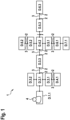
- Figure 1 shows a computer network 1 like it is in the state of the art.
- the computer network comprises a number of devices D.#1.#2, whereby #1 indicates the hierarchy and #2 is a running index.
- Each of the devices D comprise at least one network port 2.
- the network ports 2 are for example a cable interface, a fiber optic cable interface or a wireless interface.
- the devices D are interconnected with network links 3, whereby the network links are for example cables.
- the network link interconnects two devices D, especially the network link 3 interconnects two network ports 2.
- the network ports 2 are running the LLDP for discovering the network topology. For a better overview only a few exemplary network ports 2 and network links 3 are indicated.
- the first device D.1.1 is adapted to be used by a user 4.
- the user 4 can operate and/or control the first device D.1.1.
- the first device D.1.1 is for example a computer, and especially the administration computer of the commuter network 1.
- the hierarchy is the number of devices D, that are between, especially connected between, the first device D.1.1 and the concerning device.
- a device D.2.#2 is a device D that is directly linked with the device D.1.1.
- a device D.3.#2 is a device that is connected to a device D.2.#2, whereby the device D.2.# is between D.1.1 and D.3.#2.
- the user 4 is operable to crawl the computer network 1 by running the LLDP on the first device D.1.1.
- the first device D.1.1 will first discover the device D.2.1.
- Device D.2.1 will discover and report devices D.3.1, D.3.2 and D.3.3.
- the devices D.3.1, D.3.2 and D.3.3 will discover and report stations D.4.1 and D.4.2
- the device D.4.2 will discover and report devices D.5.1, D.5.2 and D.5.3, etcetera.
- One-by-one each layer in the computer network 1 will be discovered.
- the information about the layer and/or the hierarchy of devices are part of the network topology.
- the crawling and/or discovering of the computer network only discovers devices that are connected with the network link 3. If a link 3, a device D and/or a network port is not working correctly, this device D and following device will not be discovered by the first device D.1.1.
- the device D.5.3 is a faulty device, the device D.4.2 and the device D.5.3 are physically connected with a cable as network link, but the devices are not communicating using the LLDP.
- the device D.5.3 therefore cannot report its presence and can also not report the presence of the device D.6.3. Therefore also the first device cannot discover the network and/or network topology starting from D.5.3 towards D.6.3.
- Figure 2 shows a computer network 1 as an embodiment of the invention.
- the computer network 1 comprises the same amount of devices D.#1.#2 as in figure 1 .
- the devices D.#1.#2 comprise the first device D.1.1, whereby the first device is adopted to be used and/or controlled by the user 4.
- Each of the devices D.#1.#2 have at least one network port 3.
- the devices D.#1.#2 are interconnected with network links 3, whereby the devices D.#1.#2 are connected in the same way as in figure 1 .
- the computer network 1 comprise four media nodes M1, M2, M3 and M4.
- the media nodes M1, M2, M3 and M4 are for example conference units, e.g. with a microphone.
- Each media node comprise at least one media network port 5, whereby the media network port 5 may be the same type of port like the network port 3 of the devices D.#1.#2.
- Each media node M1, M2, M3 and M4 is interconnected with at least one device D.#1.#2, wherein the interconnection is preferably using the same network link, e.g. type of cable, as it is used for connecting the devices D.#1.#2.
- the media nodes M1, M2, M3 and M4 are adopted to run the media station support communication protocol and/or the service discovery protocol.
- the service discovery protocol is adopted that the media node can announce its presence to the device D.1.1.
- the media station support communication protocol is operable to crawl the computer network 1 and to do network discovery around the media node M1, M2, M3, or M4.
- the media station support communication protocol is adopted to collect media node information and to offer the media node information to D.1.1., whereby the media node information comprises information about devices around and/or the network topology around the concerning media node M1, M2, M3 or M4.
- the media station support communication protocol and the service discovery protocol is adopted to share and/or provide the media node information to the first device D.1.1.
- the first device D.1.1 is adopted to use the media node information to complete the network topology and/or to crawl the computer network 1 faster.
- the number of crawling steps whereby the number of crawling steps is also reduced, especially it is only half the number due to the presence of the media nodes M1, M2, M3 and M4.
- M1 as a fictive device D.2.2
- M2 as D.2.3
- M3 as D.2.4
- M4 as D.2.5.
- These fictive devices are crawling the network beginning at their position and announce the found device as or in the media node information. This assumes that all compatible devices announce their management address and expose their neighbor MIB.
- Figure 3 shows the computer network from figure 2 , wherein the device D.3.7 does not support announcement of the neighbor MIB. Due to the media nodes M1, M2, M3, M4 and the media station discovery protocol the network topology can be completed and the gap at device D.3.7 can be bypassed. To complete network discovery some more crawling steps are additional, in this example one more crawling step is needed than in figure 2 ..
Landscapes
- Engineering & Computer Science (AREA)
- Computer Networks & Wireless Communication (AREA)
- Signal Processing (AREA)
- Small-Scale Networks (AREA)
Claims (7)
- Computernetzwerk (1), das eine Anzahl von Vorrichtungen (D.#1.#2) und mindestens vier Medienknoten (M1, M2, M3, M4) umfasst,wobei jede der Vorrichtungen (D.#1.#2) mindestens einen Netzwerkport (2) umfasst, wobei die Vorrichtungen (D.#1.# 2) mit dem Netzwerk durch Netzwerklinks (3) verbunden sind, wobei jeder Link zwei jeweilige Netzwerkports (2) verbindet,wobei die Netzwerkports (2) gewählt sind, um ein physisches Netzwerkerkennungsprotokoll zu betreiben,wobei der Medienknoten (M1, M2, M3, M4) mindestens einen Mediennetzwerkport (5) umfasst, wobei der Medienknoten (M1, M2, M3, M4) mit mindestens einer der Vorrichtungen (D.#1.#2) durch die Netzwerklinks (3) verbunden ist, wobei der Netzwerklink (3) den Mediennetzwerkport (5) und den Netzwerkport (2) der Vorrichtung (D.#1.#2) verbindet, wobei die Medienknoten (M1, M2, M3, M4) gewählt werden, um ein Medienstations-Unterstützungs-Kommunikationsprotokoll zu betreiben und um Medienknoten-Informationen bereitzustellen, wobei das Medienstations-Unterstützungs-Kommunikationsprotokoll für eine physische Netzwerkerkennung betreibbar ist,wobei die Medienknoten (M1, M2, M3, M4) gewählt werden, um ein Diensterkennungsprotokoll zu betreiben, wobei das Diensterkennungsprotokoll so gewählt wird, dass der Medienknoten (M1, M2, M3, M4) seine Anwesenheit in dem Netzwerk ankündigen kann,wobei die Anzahl der Vorrichtungen eine erste Vorrichtung (D.1.1) umfasst, wobei die erste Vorrichtung (D.1.1) betreibbar ist, um eine Netzwerkerkennung zu starten und/oder vorzunehmen, wobei die Netzwerkerkennung an der ersten Vorrichtung (D.1.1) startet und/oder beginnt,wobei die erste Vorrichtung (D.1.1) betreibbar ist, um den Medienknoten (M1, M2, M3, M4) zu finden und/oder zu verbinden, wobei die erste Vorrichtung (D.1.1) betreibbar ist, um Medienknoteninformationen von dem Medienknoten (M1, M2, M3, M4) zu empfangen,wobei die erste Vorrichtung (D.1.1) betreibbar ist, um die Medienknoteninformationen zu verwenden, um die Topologie des Computernetzwerks (1) zu entdecken,dadurch gekennzeichnet, dass die Anzahl der Vorrichtungen (D.#1.#2) eine fehlerhafte Vorrichtung umfasst, wobei die fehlerhafte Vorrichtung das physische Netzwerkerkennungsprotokoll nicht betreibt, wobei die erste Vorrichtung (D.1.1) betreibbar ist, um die Medienknoteninformationen zu verwenden, um die Topologie des Computernetzwerks (1) zu erkennen und/oder die fehlerhafte Vorrichtung zu umgehen.
- Computernetzwerk (1) nach Anspruch 1, wobei das physische Netzwerkerkennungsprotokoll das Link-Layer-Erkennungsprotokoll ist.
- Computernetzwerk (1) nach einem der vorhergehenden Ansprüche, wobei die Medienknoteninformationen Informationen über die Netzwerktopologie um und/oder ab dem Medienknotens (M1, M2, M3, M4) umfassen.
- Computernetzwerk (1) nach einem der vorhergehenden Ansprüche, wobei die fehlerhafte Vorrichtung nicht betreibbar ist, ihre Verwaltungsadresse anzukündigen, wobei die erste Vorrichtung betreibbar ist, um die Medienknoteninformationen zu verwenden, um die Topologie des Computernetzwerks (1) zu erkennen und/oder die fehlerhafte Vorrichtung zu umgehen.
- Computernetzwerk (1) nach einem der vorhergehenden Ansprüche, wobei die erste Vorrichtung (D.1.1) und/oder ein Teil der Vorrichtungen (D.#1.#2) eine MIB umfassen.
- Computernetzwerk (1) nach einem der vorhergehenden Ansprüche, wobei der Medienknoten (M1, M2, M3, M4) eine Audiovorrichtung, eine Videovorrichtung, eine Konferenzeinheit und/oder ein Mikrofon ist.
- Verfahren zum Betreiben eines Computernetzwerks (1), wobei das Computernetzwerk (1) eine Anzahl von Vorrichtungen (D.#1.#2) und mindestens vier Medienknoten (M1, M2, M3, M4) umfasst, wobei jede der Vorrichtungen (D.#1.#2) mindestens einen Netzwerkport (2) umfasst,wobei die Vorrichtungen (D.#1.#2) mit dem Netzwerk durch Netzwerklinks (3) verbunden sind, wobei jeder Netzwerklink (3) zwei entsprechende Ports (2) verbindet,wobei die Netzwerkports (2) ein physisches Netzwerkerkennungsprotokoll betreiben, wobei der Medienknoten (M1, M2, M3, M4) einen Mediennetzwerkport (5) umfasst, wobei der Medienknoten (M1, M2, M3, M4) mit einer der Vorrichtungen (D.#1.#2) durch ein Netzwerklink (3) verbunden ist, wobei der Netzwerklink (3) den Mediennetzwerkport (5) und den Netzwerkport (3) der Vorrichtung (D.#1.#2) verbindet, wobei die Medienknoten (M1, M2, M3, M4) ein Medienstations-Unterstützungs-Nachrichtenprotokoll betreiben und Medienknoteninformationen bereitstellen, wobei das Medienstations-Unterstützungs-Nachrichtenprotokoll für eine physische Netzwerkerkennung betreibbar ist,wobei die Medienknoten (M1, M2, M3, M4) gewählt werden, um ein Diensterkennungsprotokoll zu betreiben, wobei das Diensterkennungsprotokoll so gewählt wird, dass der Medienknoten (M1, M2, M3, M4) seine Anwesenheit im Netzwerk ankündigen kann, wobei das Verfahren dadurch gekennzeichnet ist, dass die Anzahl der Vorrichtungen eine erste Vorrichtung (D.1.1) umfasst, wobei die erste Vorrichtung (D.1.1) eine Netzwerkerkennung startet und/oder durchführt, wobei die Netzwerkerkennung bei der ersten Vorrichtung (D.1.1) startet und/oder beginnt, wobei die erste Vorrichtung (D.1.1) den Medienknoten (M1, M2, M3, M4) findet und/oder verbindet,wobei die erste Vorrichtung (D.1.1) Medienknoteninformationen von dem Medienknoten (M1, M2, M3, M4) empfängt, wobei die erste Vorrichtung die Medienknoteninformationen verwendet, um die Topologie des Computernetzwerks (1) zu erkennen,Wobei die Anzahl der Vorrichtungen (D.#1.#2) eine fehlerhafte Vorrichtung umfasst, wobei die fehlerhafte Vorrichtung das physische Netzwerkerkennungsprotokoll nicht betreibt, wobei die erste Vorrichtung (D.1.1) die Medienknoteninformationen verwendet, um die Topologie des Computernetzwerks (1) zu erkennen und/oder die fehlerhafte Vorrichtung zu umgehen.
Applications Claiming Priority (1)
| Application Number | Priority Date | Filing Date | Title |
|---|---|---|---|
| PCT/EP2016/080357 WO2018103857A1 (en) | 2016-12-09 | 2016-12-09 | Computer network and method for running a computer network |
Publications (2)
| Publication Number | Publication Date |
|---|---|
| EP3552353A1 EP3552353A1 (de) | 2019-10-16 |
| EP3552353B1 true EP3552353B1 (de) | 2024-04-10 |
Family
ID=57614340
Family Applications (1)
| Application Number | Title | Priority Date | Filing Date |
|---|---|---|---|
| EP16819017.1A Active EP3552353B1 (de) | 2016-12-09 | 2016-12-09 | Computernetzwerk und verfahren zum betrieb eines computernetzwerks |
Country Status (5)
| Country | Link |
|---|---|
| US (1) | US11411827B2 (de) |
| EP (1) | EP3552353B1 (de) |
| CN (1) | CN110050440B (de) |
| AU (1) | AU2016432045B2 (de) |
| WO (1) | WO2018103857A1 (de) |
Families Citing this family (1)
| Publication number | Priority date | Publication date | Assignee | Title |
|---|---|---|---|---|
| US11336502B2 (en) * | 2020-07-07 | 2022-05-17 | Juniper Networks, Inc. | Deriving network device and host connection |
Family Cites Families (14)
| Publication number | Priority date | Publication date | Assignee | Title |
|---|---|---|---|---|
| US8514712B1 (en) * | 2007-12-06 | 2013-08-20 | Force10 Networks, Inc. | Non-stop VoIP support |
| US9497103B2 (en) * | 2008-02-29 | 2016-11-15 | Audinate Pty Limited | Isochronous local media network for performing discovery |
| DE102010008300A1 (de) * | 2010-02-17 | 2011-08-18 | Siemens Enterprise Communications GmbH & Co. KG, 81379 | Verfahren zum Verwalten von Daten in einem Kommunikationsnetz |
| US20120092441A1 (en) * | 2010-10-19 | 2012-04-19 | Cisco Technology, Inc. | System and method for providing a paring mechanism in a video environment |
| US8948029B2 (en) * | 2010-11-19 | 2015-02-03 | Red Hat, Inc. | Naming network interface cards |
| US9001667B1 (en) * | 2011-03-31 | 2015-04-07 | Amazon Technologies, Inc. | Monitoring and detecting causes of failures of network paths |
| US9148400B2 (en) * | 2012-04-12 | 2015-09-29 | Hewlett-Packard Development Company, L.P. | Automatic detection of an end node behind a phone on a computer network |
| CN103236941B (zh) * | 2013-04-03 | 2015-09-30 | 华为技术有限公司 | 一种链路发现方法和装置 |
| US9413602B2 (en) * | 2013-06-12 | 2016-08-09 | Alcatel Lucent | System, method, and apparatus for network fabric configuration in data communication networks |
| US9578117B2 (en) * | 2013-09-20 | 2017-02-21 | Amazon Technologies, Inc. | Service discovery using a network |
| US9344333B2 (en) * | 2014-05-05 | 2016-05-17 | Alcatel Lucent | Automating network build-out in self building networks |
| US10075348B2 (en) * | 2014-07-25 | 2018-09-11 | Cable Television Laboratories, Inc. | Network service discovery |
| CN104125154B (zh) * | 2014-08-12 | 2017-09-26 | 华为技术有限公司 | 网络拓扑发现方法和设备 |
| WO2018100437A1 (en) * | 2016-11-30 | 2018-06-07 | Telefonaktiebolaget Lm Ericsson (Publ) | Policy based configuration in programmable access networks |
-
2016
- 2016-12-09 WO PCT/EP2016/080357 patent/WO2018103857A1/en not_active Ceased
- 2016-12-09 AU AU2016432045A patent/AU2016432045B2/en active Active
- 2016-12-09 US US16/467,150 patent/US11411827B2/en active Active
- 2016-12-09 CN CN201680091435.9A patent/CN110050440B/zh active Active
- 2016-12-09 EP EP16819017.1A patent/EP3552353B1/de active Active
Also Published As
| Publication number | Publication date |
|---|---|
| CN110050440A (zh) | 2019-07-23 |
| WO2018103857A1 (en) | 2018-06-14 |
| EP3552353A1 (de) | 2019-10-16 |
| AU2016432045B2 (en) | 2022-03-31 |
| US20200076699A1 (en) | 2020-03-05 |
| US11411827B2 (en) | 2022-08-09 |
| AU2016432045A1 (en) | 2019-02-21 |
| CN110050440B (zh) | 2023-01-17 |
Similar Documents
| Publication | Publication Date | Title |
|---|---|---|
| US11902086B2 (en) | Method and system of a dynamic high-availability mode based on current wide area network connectivity | |
| CA2276206C (en) | Port based default virtual local area network | |
| CN102006184B (zh) | 堆叠链路管理方法、装置及网络设备 | |
| US20100014433A1 (en) | Method for processing multiple active devices in stacking system and stacking member device | |
| CN103139037A (zh) | 用于实现灵活的虚拟局域网的方法和装置 | |
| CN108173691B (zh) | 一种跨设备聚合的方法及装置 | |
| US20200076925A1 (en) | Software-defined Interconnection Method and Apparatus for Heterogeneous Protocol Data | |
| US12008382B2 (en) | Automatic formation of a virtual chassis using zero touch provisioning | |
| US9929880B2 (en) | System and method for managing VLAN associations with network ports | |
| US10686695B1 (en) | Proactive prefix disaggregation for traffic assurance in data center routing | |
| CN102291283A (zh) | 一种数字家庭网络系统 | |
| CN101631060A (zh) | 一种边缘端口的管理方法和装置 | |
| EP3552353B1 (de) | Computernetzwerk und verfahren zum betrieb eines computernetzwerks | |
| CN101420343A (zh) | Epa网络的网络拓扑发现方法 | |
| CN105812221A (zh) | 虚拟可扩展本地区域网络中数据传输的设备和方法 | |
| US10728093B2 (en) | Main device for use in a computer network, computer network, method for configuring a computer network and computer program | |
| EP1294129A2 (de) | Verfahren zum Verhindern endlose Paketübertragung in einem drahtlosen lokalen Netzwerk-System | |
| JP2008167331A (ja) | 拡張された保守ドメインレベル管理方法、通信装置、プログラム及びデータ構造 | |
| CN101227317B (zh) | 同步数字体系设备的数据通信信道的管理方法 | |
| WO2017215383A1 (zh) | 网元配置方法及装置、网元管理方法及装置 | |
| US20250126014A1 (en) | Implementation of a distributed layer two switch | |
| JP5045332B2 (ja) | パケットリングネットワークシステム、およびフォワーディングデータベース管理方法 | |
| CN118018885A (zh) | 无源光纤网络的网关管理系统 | |
| CN116599840A (zh) | 网络设备双上联管理配置方法、装置及存储介质 | |
| JP2015056858A (ja) | 情報処理装置、通信方法及び通信プログラム |
Legal Events
| Date | Code | Title | Description |
|---|---|---|---|
| STAA | Information on the status of an ep patent application or granted ep patent |
Free format text: STATUS: UNKNOWN |
|
| STAA | Information on the status of an ep patent application or granted ep patent |
Free format text: STATUS: THE INTERNATIONAL PUBLICATION HAS BEEN MADE |
|
| PUAI | Public reference made under article 153(3) epc to a published international application that has entered the european phase |
Free format text: ORIGINAL CODE: 0009012 |
|
| STAA | Information on the status of an ep patent application or granted ep patent |
Free format text: STATUS: REQUEST FOR EXAMINATION WAS MADE |
|
| 17P | Request for examination filed |
Effective date: 20190709 |
|
| AK | Designated contracting states |
Kind code of ref document: A1 Designated state(s): AL AT BE BG CH CY CZ DE DK EE ES FI FR GB GR HR HU IE IS IT LI LT LU LV MC MK MT NL NO PL PT RO RS SE SI SK SM TR |
|
| AX | Request for extension of the european patent |
Extension state: BA ME |
|
| DAV | Request for validation of the european patent (deleted) | ||
| DAX | Request for extension of the european patent (deleted) | ||
| RAP1 | Party data changed (applicant data changed or rights of an application transferred) |
Owner name: ROBERT BOSCH GMBH |
|
| STAA | Information on the status of an ep patent application or granted ep patent |
Free format text: STATUS: EXAMINATION IS IN PROGRESS |
|
| 17Q | First examination report despatched |
Effective date: 20200724 |
|
| REG | Reference to a national code |
Ref country code: DE Ref legal event code: R079 Free format text: PREVIOUS MAIN CLASS: H04L0012260000 Ipc: H04L0041120000 Ref country code: DE Ref legal event code: R079 Ref document number: 602016086862 Country of ref document: DE Free format text: PREVIOUS MAIN CLASS: H04L0012260000 Ipc: H04L0041120000 |
|
| RIC1 | Information provided on ipc code assigned before grant |
Ipc: H04L 41/12 20220101AFI20230926BHEP |
|
| GRAP | Despatch of communication of intention to grant a patent |
Free format text: ORIGINAL CODE: EPIDOSNIGR1 |
|
| STAA | Information on the status of an ep patent application or granted ep patent |
Free format text: STATUS: GRANT OF PATENT IS INTENDED |
|
| INTG | Intention to grant announced |
Effective date: 20231129 |
|
| GRAS | Grant fee paid |
Free format text: ORIGINAL CODE: EPIDOSNIGR3 |
|
| GRAA | (expected) grant |
Free format text: ORIGINAL CODE: 0009210 |
|
| STAA | Information on the status of an ep patent application or granted ep patent |
Free format text: STATUS: THE PATENT HAS BEEN GRANTED |
|
| AK | Designated contracting states |
Kind code of ref document: B1 Designated state(s): AL AT BE BG CH CY CZ DE DK EE ES FI FR GB GR HR HU IE IS IT LI LT LU LV MC MK MT NL NO PL PT RO RS SE SI SK SM TR |
|
| REG | Reference to a national code |
Ref country code: GB Ref legal event code: FG4D |
|
| REG | Reference to a national code |
Ref country code: CH Ref legal event code: EP |
|
| REG | Reference to a national code |
Ref country code: DE Ref legal event code: R096 Ref document number: 602016086862 Country of ref document: DE |
|
| REG | Reference to a national code |
Ref country code: IE Ref legal event code: FG4D |
|
| REG | Reference to a national code |
Ref country code: NL Ref legal event code: FP |
|
| REG | Reference to a national code |
Ref country code: LT Ref legal event code: MG9D |
|
| REG | Reference to a national code |
Ref country code: AT Ref legal event code: MK05 Ref document number: 1676044 Country of ref document: AT Kind code of ref document: T Effective date: 20240410 |
|
| PG25 | Lapsed in a contracting state [announced via postgrant information from national office to epo] |
Ref country code: IS Free format text: LAPSE BECAUSE OF FAILURE TO SUBMIT A TRANSLATION OF THE DESCRIPTION OR TO PAY THE FEE WITHIN THE PRESCRIBED TIME-LIMIT Effective date: 20240810 |
|
| PG25 | Lapsed in a contracting state [announced via postgrant information from national office to epo] |
Ref country code: BG Free format text: LAPSE BECAUSE OF FAILURE TO SUBMIT A TRANSLATION OF THE DESCRIPTION OR TO PAY THE FEE WITHIN THE PRESCRIBED TIME-LIMIT Effective date: 20240410 |
|
| PG25 | Lapsed in a contracting state [announced via postgrant information from national office to epo] |
Ref country code: FI Free format text: LAPSE BECAUSE OF FAILURE TO SUBMIT A TRANSLATION OF THE DESCRIPTION OR TO PAY THE FEE WITHIN THE PRESCRIBED TIME-LIMIT Effective date: 20240410 Ref country code: HR Free format text: LAPSE BECAUSE OF FAILURE TO SUBMIT A TRANSLATION OF THE DESCRIPTION OR TO PAY THE FEE WITHIN THE PRESCRIBED TIME-LIMIT Effective date: 20240410 |
|
| PG25 | Lapsed in a contracting state [announced via postgrant information from national office to epo] |
Ref country code: GR Free format text: LAPSE BECAUSE OF FAILURE TO SUBMIT A TRANSLATION OF THE DESCRIPTION OR TO PAY THE FEE WITHIN THE PRESCRIBED TIME-LIMIT Effective date: 20240711 |
|
| PG25 | Lapsed in a contracting state [announced via postgrant information from national office to epo] |
Ref country code: PT Free format text: LAPSE BECAUSE OF FAILURE TO SUBMIT A TRANSLATION OF THE DESCRIPTION OR TO PAY THE FEE WITHIN THE PRESCRIBED TIME-LIMIT Effective date: 20240812 |
|
| PG25 | Lapsed in a contracting state [announced via postgrant information from national office to epo] |
Ref country code: ES Free format text: LAPSE BECAUSE OF FAILURE TO SUBMIT A TRANSLATION OF THE DESCRIPTION OR TO PAY THE FEE WITHIN THE PRESCRIBED TIME-LIMIT Effective date: 20240410 |
|
| PG25 | Lapsed in a contracting state [announced via postgrant information from national office to epo] |
Ref country code: AT Free format text: LAPSE BECAUSE OF FAILURE TO SUBMIT A TRANSLATION OF THE DESCRIPTION OR TO PAY THE FEE WITHIN THE PRESCRIBED TIME-LIMIT Effective date: 20240410 |
|
| PG25 | Lapsed in a contracting state [announced via postgrant information from national office to epo] |
Ref country code: PL Free format text: LAPSE BECAUSE OF FAILURE TO SUBMIT A TRANSLATION OF THE DESCRIPTION OR TO PAY THE FEE WITHIN THE PRESCRIBED TIME-LIMIT Effective date: 20240410 |
|
| PG25 | Lapsed in a contracting state [announced via postgrant information from national office to epo] |
Ref country code: LV Free format text: LAPSE BECAUSE OF FAILURE TO SUBMIT A TRANSLATION OF THE DESCRIPTION OR TO PAY THE FEE WITHIN THE PRESCRIBED TIME-LIMIT Effective date: 20240410 |
|
| PG25 | Lapsed in a contracting state [announced via postgrant information from national office to epo] |
Ref country code: PT Free format text: LAPSE BECAUSE OF FAILURE TO SUBMIT A TRANSLATION OF THE DESCRIPTION OR TO PAY THE FEE WITHIN THE PRESCRIBED TIME-LIMIT Effective date: 20240812 Ref country code: PL Free format text: LAPSE BECAUSE OF FAILURE TO SUBMIT A TRANSLATION OF THE DESCRIPTION OR TO PAY THE FEE WITHIN THE PRESCRIBED TIME-LIMIT Effective date: 20240410 Ref country code: NO Free format text: LAPSE BECAUSE OF FAILURE TO SUBMIT A TRANSLATION OF THE DESCRIPTION OR TO PAY THE FEE WITHIN THE PRESCRIBED TIME-LIMIT Effective date: 20240710 Ref country code: LV Free format text: LAPSE BECAUSE OF FAILURE TO SUBMIT A TRANSLATION OF THE DESCRIPTION OR TO PAY THE FEE WITHIN THE PRESCRIBED TIME-LIMIT Effective date: 20240410 Ref country code: IS Free format text: LAPSE BECAUSE OF FAILURE TO SUBMIT A TRANSLATION OF THE DESCRIPTION OR TO PAY THE FEE WITHIN THE PRESCRIBED TIME-LIMIT Effective date: 20240810 Ref country code: HR Free format text: LAPSE BECAUSE OF FAILURE TO SUBMIT A TRANSLATION OF THE DESCRIPTION OR TO PAY THE FEE WITHIN THE PRESCRIBED TIME-LIMIT Effective date: 20240410 Ref country code: GR Free format text: LAPSE BECAUSE OF FAILURE TO SUBMIT A TRANSLATION OF THE DESCRIPTION OR TO PAY THE FEE WITHIN THE PRESCRIBED TIME-LIMIT Effective date: 20240711 Ref country code: FI Free format text: LAPSE BECAUSE OF FAILURE TO SUBMIT A TRANSLATION OF THE DESCRIPTION OR TO PAY THE FEE WITHIN THE PRESCRIBED TIME-LIMIT Effective date: 20240410 Ref country code: ES Free format text: LAPSE BECAUSE OF FAILURE TO SUBMIT A TRANSLATION OF THE DESCRIPTION OR TO PAY THE FEE WITHIN THE PRESCRIBED TIME-LIMIT Effective date: 20240410 Ref country code: BG Free format text: LAPSE BECAUSE OF FAILURE TO SUBMIT A TRANSLATION OF THE DESCRIPTION OR TO PAY THE FEE WITHIN THE PRESCRIBED TIME-LIMIT Effective date: 20240410 Ref country code: AT Free format text: LAPSE BECAUSE OF FAILURE TO SUBMIT A TRANSLATION OF THE DESCRIPTION OR TO PAY THE FEE WITHIN THE PRESCRIBED TIME-LIMIT Effective date: 20240410 Ref country code: RS Free format text: LAPSE BECAUSE OF FAILURE TO SUBMIT A TRANSLATION OF THE DESCRIPTION OR TO PAY THE FEE WITHIN THE PRESCRIBED TIME-LIMIT Effective date: 20240710 |
|
| REG | Reference to a national code |
Ref country code: DE Ref legal event code: R097 Ref document number: 602016086862 Country of ref document: DE |
|
| PG25 | Lapsed in a contracting state [announced via postgrant information from national office to epo] |
Ref country code: DK Free format text: LAPSE BECAUSE OF FAILURE TO SUBMIT A TRANSLATION OF THE DESCRIPTION OR TO PAY THE FEE WITHIN THE PRESCRIBED TIME-LIMIT Effective date: 20240410 |
|
| PG25 | Lapsed in a contracting state [announced via postgrant information from national office to epo] |
Ref country code: EE Free format text: LAPSE BECAUSE OF FAILURE TO SUBMIT A TRANSLATION OF THE DESCRIPTION OR TO PAY THE FEE WITHIN THE PRESCRIBED TIME-LIMIT Effective date: 20240410 |
|
| PG25 | Lapsed in a contracting state [announced via postgrant information from national office to epo] |
Ref country code: CZ Free format text: LAPSE BECAUSE OF FAILURE TO SUBMIT A TRANSLATION OF THE DESCRIPTION OR TO PAY THE FEE WITHIN THE PRESCRIBED TIME-LIMIT Effective date: 20240410 |
|
| PG25 | Lapsed in a contracting state [announced via postgrant information from national office to epo] |
Ref country code: SK Free format text: LAPSE BECAUSE OF FAILURE TO SUBMIT A TRANSLATION OF THE DESCRIPTION OR TO PAY THE FEE WITHIN THE PRESCRIBED TIME-LIMIT Effective date: 20240410 Ref country code: RO Free format text: LAPSE BECAUSE OF FAILURE TO SUBMIT A TRANSLATION OF THE DESCRIPTION OR TO PAY THE FEE WITHIN THE PRESCRIBED TIME-LIMIT Effective date: 20240410 |
|
| PG25 | Lapsed in a contracting state [announced via postgrant information from national office to epo] |
Ref country code: SM Free format text: LAPSE BECAUSE OF FAILURE TO SUBMIT A TRANSLATION OF THE DESCRIPTION OR TO PAY THE FEE WITHIN THE PRESCRIBED TIME-LIMIT Effective date: 20240410 |
|
| PG25 | Lapsed in a contracting state [announced via postgrant information from national office to epo] |
Ref country code: SM Free format text: LAPSE BECAUSE OF FAILURE TO SUBMIT A TRANSLATION OF THE DESCRIPTION OR TO PAY THE FEE WITHIN THE PRESCRIBED TIME-LIMIT Effective date: 20240410 Ref country code: SK Free format text: LAPSE BECAUSE OF FAILURE TO SUBMIT A TRANSLATION OF THE DESCRIPTION OR TO PAY THE FEE WITHIN THE PRESCRIBED TIME-LIMIT Effective date: 20240410 Ref country code: RO Free format text: LAPSE BECAUSE OF FAILURE TO SUBMIT A TRANSLATION OF THE DESCRIPTION OR TO PAY THE FEE WITHIN THE PRESCRIBED TIME-LIMIT Effective date: 20240410 Ref country code: EE Free format text: LAPSE BECAUSE OF FAILURE TO SUBMIT A TRANSLATION OF THE DESCRIPTION OR TO PAY THE FEE WITHIN THE PRESCRIBED TIME-LIMIT Effective date: 20240410 Ref country code: DK Free format text: LAPSE BECAUSE OF FAILURE TO SUBMIT A TRANSLATION OF THE DESCRIPTION OR TO PAY THE FEE WITHIN THE PRESCRIBED TIME-LIMIT Effective date: 20240410 Ref country code: CZ Free format text: LAPSE BECAUSE OF FAILURE TO SUBMIT A TRANSLATION OF THE DESCRIPTION OR TO PAY THE FEE WITHIN THE PRESCRIBED TIME-LIMIT Effective date: 20240410 |
|
| PG25 | Lapsed in a contracting state [announced via postgrant information from national office to epo] |
Ref country code: IT Free format text: LAPSE BECAUSE OF FAILURE TO SUBMIT A TRANSLATION OF THE DESCRIPTION OR TO PAY THE FEE WITHIN THE PRESCRIBED TIME-LIMIT Effective date: 20240410 |
|
| PLBE | No opposition filed within time limit |
Free format text: ORIGINAL CODE: 0009261 |
|
| STAA | Information on the status of an ep patent application or granted ep patent |
Free format text: STATUS: NO OPPOSITION FILED WITHIN TIME LIMIT |
|
| 26N | No opposition filed |
Effective date: 20250113 |
|
| PG25 | Lapsed in a contracting state [announced via postgrant information from national office to epo] |
Ref country code: SI Free format text: LAPSE BECAUSE OF FAILURE TO SUBMIT A TRANSLATION OF THE DESCRIPTION OR TO PAY THE FEE WITHIN THE PRESCRIBED TIME-LIMIT Effective date: 20240410 |
|
| PG25 | Lapsed in a contracting state [announced via postgrant information from national office to epo] |
Ref country code: MC Free format text: LAPSE BECAUSE OF FAILURE TO SUBMIT A TRANSLATION OF THE DESCRIPTION OR TO PAY THE FEE WITHIN THE PRESCRIBED TIME-LIMIT Effective date: 20240410 |
|
| REG | Reference to a national code |
Ref country code: CH Ref legal event code: PL |
|
| PG25 | Lapsed in a contracting state [announced via postgrant information from national office to epo] |
Ref country code: LU Free format text: LAPSE BECAUSE OF NON-PAYMENT OF DUE FEES Effective date: 20241209 |
|
| PG25 | Lapsed in a contracting state [announced via postgrant information from national office to epo] |
Ref country code: SE Free format text: LAPSE BECAUSE OF FAILURE TO SUBMIT A TRANSLATION OF THE DESCRIPTION OR TO PAY THE FEE WITHIN THE PRESCRIBED TIME-LIMIT Effective date: 20240410 |
|
| REG | Reference to a national code |
Ref country code: BE Ref legal event code: MM Effective date: 20241231 |
|
| PG25 | Lapsed in a contracting state [announced via postgrant information from national office to epo] |
Ref country code: BE Free format text: LAPSE BECAUSE OF NON-PAYMENT OF DUE FEES Effective date: 20241231 |
|
| PG25 | Lapsed in a contracting state [announced via postgrant information from national office to epo] |
Ref country code: CH Free format text: LAPSE BECAUSE OF NON-PAYMENT OF DUE FEES Effective date: 20241231 |
|
| PG25 | Lapsed in a contracting state [announced via postgrant information from national office to epo] |
Ref country code: IE Free format text: LAPSE BECAUSE OF NON-PAYMENT OF DUE FEES Effective date: 20241209 |
|
| PGFP | Annual fee paid to national office [announced via postgrant information from national office to epo] |
Ref country code: DE Payment date: 20251110 Year of fee payment: 10 |
|
| PGFP | Annual fee paid to national office [announced via postgrant information from national office to epo] |
Ref country code: GB Payment date: 20251218 Year of fee payment: 10 |
|
| PGFP | Annual fee paid to national office [announced via postgrant information from national office to epo] |
Ref country code: FR Payment date: 20251218 Year of fee payment: 10 Ref country code: NL Payment date: 20251217 Year of fee payment: 10 |