EP3552008B1 - Verfahren und vorrichtung zur prüfung einer verbindung zwischen zwei substraten - Google Patents
Verfahren und vorrichtung zur prüfung einer verbindung zwischen zwei substraten Download PDFInfo
- Publication number
- EP3552008B1 EP3552008B1 EP17821687.5A EP17821687A EP3552008B1 EP 3552008 B1 EP3552008 B1 EP 3552008B1 EP 17821687 A EP17821687 A EP 17821687A EP 3552008 B1 EP3552008 B1 EP 3552008B1
- Authority
- EP
- European Patent Office
- Prior art keywords
- signal
- substrate
- substrates
- transducer
- excitation
- Prior art date
- Legal status (The legal status is an assumption and is not a legal conclusion. Google has not performed a legal analysis and makes no representation as to the accuracy of the status listed.)
- Active
Links
Images
Classifications
-
- G—PHYSICS
- G01—MEASURING; TESTING
- G01N—INVESTIGATING OR ANALYSING MATERIALS BY DETERMINING THEIR CHEMICAL OR PHYSICAL PROPERTIES
- G01N29/00—Investigating or analysing materials by the use of ultrasonic, sonic or infrasonic waves; Visualisation of the interior of objects by transmitting ultrasonic or sonic waves through the object
- G01N29/44—Processing the detected response signal, e.g. electronic circuits specially adapted therefor
- G01N29/46—Processing the detected response signal, e.g. electronic circuits specially adapted therefor by spectral analysis, e.g. Fourier analysis or wavelet analysis
-
- G—PHYSICS
- G01—MEASURING; TESTING
- G01N—INVESTIGATING OR ANALYSING MATERIALS BY DETERMINING THEIR CHEMICAL OR PHYSICAL PROPERTIES
- G01N29/00—Investigating or analysing materials by the use of ultrasonic, sonic or infrasonic waves; Visualisation of the interior of objects by transmitting ultrasonic or sonic waves through the object
- G01N29/04—Analysing solids
- G01N29/043—Analysing solids in the interior, e.g. by shear waves
-
- G—PHYSICS
- G01—MEASURING; TESTING
- G01N—INVESTIGATING OR ANALYSING MATERIALS BY DETERMINING THEIR CHEMICAL OR PHYSICAL PROPERTIES
- G01N29/00—Investigating or analysing materials by the use of ultrasonic, sonic or infrasonic waves; Visualisation of the interior of objects by transmitting ultrasonic or sonic waves through the object
- G01N29/04—Analysing solids
- G01N29/11—Analysing solids by measuring attenuation of acoustic waves
-
- G—PHYSICS
- G01—MEASURING; TESTING
- G01N—INVESTIGATING OR ANALYSING MATERIALS BY DETERMINING THEIR CHEMICAL OR PHYSICAL PROPERTIES
- G01N29/00—Investigating or analysing materials by the use of ultrasonic, sonic or infrasonic waves; Visualisation of the interior of objects by transmitting ultrasonic or sonic waves through the object
- G01N29/44—Processing the detected response signal, e.g. electronic circuits specially adapted therefor
- G01N29/4472—Mathematical theories or simulation
-
- G—PHYSICS
- G01—MEASURING; TESTING
- G01N—INVESTIGATING OR ANALYSING MATERIALS BY DETERMINING THEIR CHEMICAL OR PHYSICAL PROPERTIES
- G01N2291/00—Indexing codes associated with group G01N29/00
- G01N2291/01—Indexing codes associated with the measuring variable
- G01N2291/015—Attenuation, scattering
-
- G—PHYSICS
- G01—MEASURING; TESTING
- G01N—INVESTIGATING OR ANALYSING MATERIALS BY DETERMINING THEIR CHEMICAL OR PHYSICAL PROPERTIES
- G01N2291/00—Indexing codes associated with group G01N29/00
- G01N2291/02—Indexing codes associated with the analysed material
- G01N2291/028—Material parameters
- G01N2291/02827—Elastic parameters, strength or force
-
- G—PHYSICS
- G01—MEASURING; TESTING
- G01N—INVESTIGATING OR ANALYSING MATERIALS BY DETERMINING THEIR CHEMICAL OR PHYSICAL PROPERTIES
- G01N2291/00—Indexing codes associated with group G01N29/00
- G01N2291/04—Wave modes and trajectories
- G01N2291/042—Wave modes
- G01N2291/0427—Flexural waves, plate waves, e.g. Lamb waves, tuning fork, cantilever
-
- G—PHYSICS
- G01—MEASURING; TESTING
- G01N—INVESTIGATING OR ANALYSING MATERIALS BY DETERMINING THEIR CHEMICAL OR PHYSICAL PROPERTIES
- G01N2291/00—Indexing codes associated with group G01N29/00
- G01N2291/10—Number of transducers
- G01N2291/101—Number of transducers one transducer
-
- G—PHYSICS
- G01—MEASURING; TESTING
- G01N—INVESTIGATING OR ANALYSING MATERIALS BY DETERMINING THEIR CHEMICAL OR PHYSICAL PROPERTIES
- G01N2291/00—Indexing codes associated with group G01N29/00
- G01N2291/26—Scanned objects
- G01N2291/267—Welds
Definitions
- the present application relates to a method and a device for controlling the quality of a bond between two substrates.
- the substrates can be of the same nature, that is to say of identical materials, or of different types, that is to say of different materials.
- step d) comprises determining, from the determined average frequency difference ⁇ f, a value representative of the adhesion energy between the first and second substrates.
- the series of peaks comprises at least 4 peaks.
- the return signal comprises at least two successive echoes of the excitation signal on the rear face of the second substrate.
- the return signal comprises three successive echoes of the excitation signal on the rear face of the second substrate.
- the return signal is measured during two consecutive time ranges T1 and T2, the range T1 comprising only a surface echo of the excitation signal returned directly by the front face of the first substrate , and the range T2 comprising said at least one echo of the excitation signal on the rear face of the second substrate; and in step c), the calculated spectral signal corresponds to the ratio of a frequency transpose of the return signal measured during the range T1 + T2 to a frequency transpose of the return signal measured during the range T1.
- the ultrasonic excitation signal has a frequency between 100 MHz and 1 GHz.
- the duration of the ultrasonic excitation signal is less than 1 ⁇ s.
- steps a) to d) are repeated a plurality of times by moving the ultrasound transducer parallel to the mean plane of the assembly between two successive iterations, so as to obtain an image or map of the quality of the bonding between the two substrates.
- the ultrasonic excitation signal is emitted at normal incidence with respect to the front face of the first substrate.
- Another embodiment provides a device for controlling an assembly comprising first and second substrates each having a front face and a rear face, the rear face of the first substrate being bonded to the front face of the second substrate, this device comprising a transducer ultrasound and a processing device configured to implement a control method as defined above.
- the figures 1 and 2 illustrate in more detail the problem mentioned above, which arises when one seeks to apply the interface characterization methods described in the aforementioned articles, to control the quality of a bond between two substrates of the same nature, in the case where the interface roughness between the two substrates are very small, for example less than 1 nm in root mean square.
- direct bonding that is to say without providing an adhesive polymer material at the interface between the two substrates, for example molecular bonding.
- thermocompression bonding eutectic bonding
- anodic bonding anodic bonding.
- Direct bonding can for example be carried out by applying the substrates against each other at ambient temperature and pressure. Thermal annealing can then be carried out to increase the adhesion energy or bonding energy. As a variant, the bonding can be carried out under vacuum. As a variant, the bonding can be carried out hot and under pressure (thermocompression), with or without application of an electrical voltage.
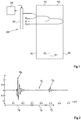
- the figure 1 is a schematic sectional view of an example of a device 100 for controlling the quality of a bond between two substrates W1 and W2.
- the substrate W1 has front A1 and rear B1 main faces that are substantially plane and parallel, and the substrate W2 has front A2 and rear B2 main faces that are substantially flat and parallel.
- the rear face of the substrate W1 is bonded by direct bonding to the front face of the substrate W2.
- the substrates W1 and W2 are of the same nature, for example in silicon or glass.
- the surface roughness at the interface between the two substrates that is to say the roughness of the surfaces B1 and A2 before bonding, are of very small dimensions, for example less than 1 nm in root mean square.
- the device 100 comprises an ultrasonic transducer 101, for example a planar transducer, placed opposite the front face A1 of the substrate W1.
- the device 100 further comprises a control and processing circuit 103 connected to the ultrasonic transducer 101, adapted to control the emission of ultrasonic signals by the transducer 101, and to read and analyze ultrasonic signals received by the transducer 101.
- the ultrasound transducer 101 is placed at a distance from the front face A1 of the substrate W1, and not in contact with the front face of the substrate W1.
- an acoustic coupling liquid for example water or anhydrous alcohol, is preferably disposed between the transducer and the assembly of the substrates.
- the transducer 101 can be placed in contact with the front face A1 of the substrate W1.
- the control and processing circuit 103 firstly controls the transducer 101 to emit an ultrasonic excitation signal in the direction of the front face A1 of the substrate W1, for example at normal incidence with respect to the front face A1 of the substrate W1.
- the transducer 101 is controlled by the control and processing circuit 103 to measure a return signal reflected by the assembly comprising the substrates W1 and W2.
- This reflected return signal comprises a set of contributions, each contribution corresponding to a echo of the excitation signal generated when the excitation signal encounters a change of medium.
- a first echo E S of the excitation signal is reflected directly towards the transducer by the front face A1 of the substrate W1.
- a part of the excitation signal not reflected by the front face A1 of the substrate W1 penetrates the substrate W1, then is reflected on the interface between the substrates W1 and W2.
- a second echo E I of the excitation signal, or interface echo is thus sent back to the transducer by the interface between the substrates W1 and W2.
- a part of the excitation signal not reflected by the front face A1 of the substrate W1 and not reflected by the interface between the substrates W1 and W2 enters the substrate W2 and is reflected on the rear face B2 of the substrate W2.
- a third echo E F of the excitation signal, or background echo is thus sent back to the transducer by the rear face B2 of the substrate W2.
- the ultrasonic excitation frequency and the duration of the excitation signal are chosen, taking into account the distance between the transducer and the substrate W1 and the thickness of each of the substrates W1 and W2, so that the three echoes E S , E I and E F can be separated in time.
- the excitation signal is an ultrasonic pulse or wave train with a duration of the order of 0.1 ⁇ s, and the frequency of the excitation signal is approximately 50 MHz.
- the duration of the excitation signal is small compared to the time of flight in each of the layers, and the time separation of the three echoes.
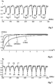
- the figure 2 is a chronogram illustrating the evolution, as a function of time t (in ⁇ s on the abscissa), of the amplitude A (on the ordinate) of the return ultrasonic signal measured by the transducer 101 of the figure 1 , following the emission of an ultrasonic excitation signal in the direction of the front face A1 of the substrate W1.
- T S , T I and T F Three successive time ranges T S , T I and T F have been represented on the figure 1 , corresponding respectively to the reception ranges of the echoes E S , E I and E F by the transducer.
- the control method based on the methods described in the aforementioned prior art articles comprises the selection of the single interface echo E I , by temporal filtering of the return signal measured by the transducer 101.
- the control circuit and processing 103 carries out temporal filtering of the measured return signal so as to keep only the signal received during the range T I.
- a transpose, in the frequency domain, of the selected signal is then calculated by the circuit 103.
- the circuit 103 calculates a Fourier transform of the signal measured by the transducer during the range T I. From the frequency transpose of the echo signal E I , the circuit 103 generates a spectral signal representative of the change in frequency of the reflection coefficient of the interface between the two substrates. An analysis of this spectral signal is then carried out by the circuit 103 to determine information concerning the properties of the interface between the substrates W1 and W2.
- a problem with this method is that, as shown on the figure 2 , in the case considered above where the substrates W1 and W2 are of the same nature, are bonded by direct bonding, and have surface roughness of very small dimensions at the interface between the two substrates, the echo E I received by the transducer in the window T I is generally too weak to be able to be distinguished from the measurement noise. In other words, the reflection coefficient of the interface is close to zero, which prevents any direct use of this coefficient to assess the quality of the bonding.
- the tests carried out by the inventors have in particular shown that the echo E I remains practically undetectable even when the quality of the bonding is poor.
- the curve of the figure 2 corresponds to a signal measured in the case of direct bonding (or molecular bonding) silicon / silicon carried out voluntarily to have a low adhesion energy, of the order of 0.05 Jm -2 , while direct bonding silicon / silicon is generally considered satisfactory when the energy adhesion between the two substrates is at least 0.2 Jm -2 and preferably at least 0.4 Jm -2 .
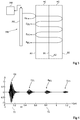
- the figure 3 is a schematic sectional view of an example of an embodiment of a device 300 for controlling the quality of a bond between two substrates W1 and W2.
- the assembly comprising the substrates W1 and W2 is identical or similar to what has been described above.
- Each of the substrates W1 and W2 has for example a thickness between 100 ⁇ m and 1 mm.
- the substrates W1 and W2 have substantially the same thickness.
- the substrates W1 and W2 can have different thicknesses.
- the thickness of the thinnest of the two substrates W1 and W2 is preferably at least equal to one tenth of the thickness of the other substrate.
- the device 300 comprises an ultrasonic transducer 301, for example identical or similar to the transducer 101 of the figure 1 , placed vis-à-vis the front face A1 of the substrate W1.
- the device 300 further comprises a control and processing circuit 303 connected to the ultrasonic transducer 301, adapted to control the emission of ultrasonic signals by the transducer 301, and to read and analyze the ultrasonic signals received by the transducer 301.
- the transducer 301 of the figure 3 is placed at a distance from the front face A1 of the substrate W1, and not in contact with the front face of the substrate W1.
- the embodiments described are not limited to this particular case.
- the assembly comprising the transducer 301 and the substrates W1 and W2 can be immersed in an acoustic coupling liquid, for example water or anhydrous alcohol.
- an acoustic coupling liquid for example water or anhydrous alcohol.
- the peripheral edges of the assembly comprising the substrates W1 and W2 can be protected, for example by a waterproof paraffin insulation or any other suitable material, so as to avoid penetration of the acoustic coupling liquid between the two substrates, which could degrade or modify the bonding.
- control and processing circuit 303 firstly controls the transducer 301 to emit an ultrasonic excitation signal in the direction of the front face A1 of the substrate W1, for example at normal incidence with respect to the front face A1 of the substrate W1.
- the transducer 301 is controlled by the control and processing circuit 303 to measure a return signal reflected by the assembly comprising the substrates W1 and W2.
- a first echo E S of the excitation signal is returned directly to the transducer by the front face A1 of the substrate W1.
- the part of the excitation signal entering the substrate W1 via its front face A1 passes through the substrate W1 then the substrate W2, and is reflected a first time on the rear face B2 of the substrate W2.
- a second echo E F1 or first background echo, is thus returned to the transducer after reflection on the rear face B2 of the substrate W2.
- the background echo E F1 received by the transducer 301 only comprises part of the signal resulting from the first reflection of the excitation signal on the rear face B2 of the substrate W2. Indeed, part of the signal reflected by the rear face B2 of the substrate W2 is reflected again by the front face A1 of the substrate W1, and is therefore not directly transmitted to the transducer 301.
- the signal reflected on the front face A1 of the substrate W1 once again passes through the two substrates W1 and W2 and is reflected again on the rear face B2 of the substrate W2.
- a third echo E F2 or second background echo, is thus sent back to the transducer by the rear face B2 of the substrate W2.
- the background echo E F2 received by the transducer 301 only comprises part of the signal resulting from the second reflection of the excitation signal on the rear face B2 of the substrate W2. Indeed, part of the signal reflected by the rear face B2 of the substrate W2 is reflected again on the front face A1 of the substrate W1, and is therefore not directly transmitted to the transducer 301.
- the signal reflected on the front face A1 of the substrate W1 once again passes through the two substrates W1 and W2 and is reflected again on the rear face B2 of the substrate W2.
- a fourth echo E F3 or third background echo, is thus returned to the transducer by the rear face B2 of the substrate W2, and so on until complete fading of the excitation signal.
- the ultrasonic excitation frequency and the duration of the excitation signal are preferably chosen, taking into account the distance between the transducer and the substrate W1 and the thickness of each of the substrates W1 and W2, so that the surface echo E S on the one hand, and background echoes E F1 , E F2 , E F3 , etc. on the other hand, can be separated in time. It will be noted that, as will emerge more clearly from the remainder of the description, an advantage of the proposed method is that the background echoes E F1 , E F2 , E F3 , etc. do not need to be temporally separable from each other.
- the excitation signal is a pulse or an ultrasonic wave train of duration less than 1 ⁇ s, and preferably less than 0.5 ⁇ s, and the frequency of the excitation signal is between 1 MHz and 10 GHz, and preferably between 100 MHz and 1 GHz.
- the figure 4 is a chronogram illustrating the evolution, as a function of time t (in ⁇ s on the abscissa), of the amplitude A (on the ordinate) of the return ultrasonic signal measured by the transducer 301 in the system of the figure 3 , following the emission of an ultrasonic excitation signal in the direction of the front face A1 of the substrate W1.
- the duration of the excitation signal is approximately 0.1 ⁇ s
- the frequency of the excitation signal is of the order of 200 MHz.
- the range T1 comprises only the surface echo E S returned directly by the front face A1 of the assembly
- the range T2 comprises subsequent echoes returned by the assembly and in particular the three successive background echoes E F1 , E F2 and E F3 .
- the control method implemented by the device 300 comprises the selection, by the control and processing circuit 303, by temporal filtering of the return signal measured by the transducer 301, of the return signal received during the single range temporal T2.
- the method may further comprise the selection, by the control and processing circuit 303, by temporal filtering of the return signal measured by the transducer 301, of the return signal received during the single time range T1.
- a transpose, in the frequency domain, of the signal measured by the transducer during the range T2, is then calculated by the circuit 303.
- the circuit 303 calculates a Fourier transform of the signal measured during the range T2.
- the circuit 303 From the frequency transpose of the signal measured during the range T2, the circuit 303 generates a spectral signal Rg representative of the frequency evolution of a global reflection coefficient of the structure, defined as being the ratio the return signal measured by the transducer, on the excitation signal emitted by the transducer.
- control method implemented by the device 300 comprises the selection, by the control and processing circuit 303, by temporal filtering of the return signal measured by the transducer 301, of the return signal received during the period. 'set of time ranges T1 and T2, called range T1 + T2.
- the method may further comprise the selection, by the control and processing circuit 303, by temporal filtering of the return signal measured by the transducer 301, of the return signal received during the single time range T1.
- the circuit 303 calculates a Fourier transform of the signal measured during the range T1 + T2.
- the circuit 303 From the frequency transpose of the signal measured during the range T1 + T2, the circuit 303 generates a spectral signal Rg representative of the frequency evolution of an overall reflection coefficient of the structure, defined as being the ratio of the signal received by the transducer, on the excitation signal emitted by the transducer.
- the term FFT (T1) of the definition of the coefficient R g can be replaced by any other frequency representation of the excitation signal emitted by the transducer, for example a frequency transpose a reference signal taken directly from the transducer during the phase of transmission of the excitation signal by the transducer.
- the proposed control method can advantageously be implemented, in its second variant, even when the surface echo E S cannot be separated in time from the background echoes E F1 , E F2 , E F3 , etc. .
- the figure 5 is a spectrogram representing the evolution, as a function of the frequency f (on the abscissa in MHz), of the overall reflection coefficient R g (on the ordinate) as defined above, calculated by the processing circuit 303 from the signal return measured by transducer 301.
- the overall reflection coefficient R g presents a succession of local minima or resonance peaks P1, P2, P3, P4, P5, P6, P7, P8, P9, P10, regularly distributed over the measurement frequency range (ranging from 190 at 220 MHz in the example shown and corresponding to the pass band in reception of the ultrasonic transducer 301).
- the frequency position of the symmetrical resonance peaks (the peaks of even rows in this example) varies significantly as a function of the quality of the bonding between the substrates W1 and W2, and more particularly as a function of the energy of adhesion between the substrates W1 and W2.
- the position of the antisymmetric resonance peaks (the peaks of odd rows in this example) is however independent of the quality of the bond between the substrates.
- the inventors explain this behavior by the fact that the resonances in symmetrical Lamb modes do not induce a significant displacement of the medium of the assembly between the two substrates, but generate, at the level of the medium of the assembly (at the interface between the two substrates in the example shown), contraction / expansion stresses in a direction orthogonal to the interface plane.
- the interface is therefore relatively highly stressed by the resonances in symmetric Lamb modes, from which it follows that the quality of the bonding influences the frequency of the resonances in symmetric Lamb modes.
- resonances in antisymmetric Lamb modes cause displacement of the entire structure, but do not generate significant compressive / expansion stress at the interface. The quality of the bonding therefore has little or no influence on the frequency of the resonances in antisymmetric Lamb modes.
- the frequency difference between two consecutive peaks of the signal R g is representative of the quality of the bonding between the substrates W1 and W2.
- the control method implemented by the device 300 comprises the detection, by the processing circuit 303, of at least two consecutive local minima of the signal R g , corresponding to two consecutive symmetrical and antisymmetric or antisymmetric and symmetrical resonances of the signal R g , for example resonances in Lamb modes, and the measurement of the frequency difference between these two peaks.
- the inventors have more particularly observed that the frequency of the symmetrical resonance peaks (the peaks of even rank in the example shown) decreases when the quality of the bonding deteriorates.
- the frequency difference ⁇ f between an antisymmetric resonance peak and the symmetrical resonance peak of the immediately higher rank is all the lower the lower the quality of the bonding, and vice versa.
- the evaluation of the quality of the interface between the substrates W1 and W2 can therefore be based on the measurement of the frequency difference between the antisymmetric resonance peaks and the symmetrical resonance peaks.
- the frequency difference between each antisymmetric resonance peak and the symmetrical resonance peak of the immediately higher rank is substantially constant over the entire measured frequency range.
- a single measurement of the frequency difference ⁇ f between an antisymmetric resonance peak and the symmetrical resonance peak of the immediately higher rank therefore makes it possible to obtain information as to the quality of the bonding between the substrates.
- the frequency difference ⁇ f used to evaluate the quality of the interface between the substrates W1 and W2 corresponds to the average of the values ⁇ f 1 , ⁇ f 2 , ⁇ f 3 , ⁇ f 4 , ⁇ f 5 .
- the embodiments described are not limited to the example shown in which the frequency range for measuring the signal R g includes ten resonance peaks.
- the embodiments described apply more generally whatever the extent of the frequency range of measurement of the signal R g , provided that the latter comprises at least two and preferably at least four peaks corresponding to resonances, for example example in Lamb modes, of the assembly formed by the substrates W1 and W2.
- the detection of the resonance peaks by the control and processing circuit 303 can be implemented by any known local minima detection method. Such methods are within the reach of those skilled in the art and will not be detailed here.
- the detection of the resonance peaks can in particular include a thresholding to filter out any parasitic peaks.
- the antisymmetric resonance peaks are the peaks of odd rank or the peaks of even rank.
- the figure 6 is a diagram representing the evolution observed by the inventors of the frequency difference ⁇ f (in MHz, on the ordinate) measured between the antisymmetric and symmetrical resonance peaks of the spectral signal R g (f), as a function of the energy of adhesion E (in Jm -2 , on the abscissa) between the two substrates.
- the figure 6 more particularly comprises a curve C2 corresponding to the case considered above of an ultrasonic excitation carried out at a frequency of the order of 200 MHz.
- the figure 6 furthermore comprises a curve C1 corresponding to an ultrasonic excitation at a frequency of the order of 40 MHz, and a curve C3 corresponding to an ultrasonic excitation at a frequency of the order of 1 GHz.
- curves C1, C2 and C3 are monotonic increasing curves, i.e. the higher the adhesion energy E between the two substrates, the greater the frequency difference ⁇ f measured between an antisymmetric resonance peak and the symmetrical resonance peak of immediately higher rank of the spectral signal R g is high, and vice versa.
- the law h can then be stored by the control and processing circuit 303, for example in the form of a correspondence table or in the form of an analytical law.
- the control method implemented by the device 300 may include a step of determining, by the processing circuit 303, from the value ⁇ f measured on the signal R g and by applying the law h, a value representative of the adhesion energy between the two substrates W1 and W2.
- the return signal measured by the transducer during the time range T2 taken into account to calculate the overall reflection coefficient R g of the assembly, comprises three successive background echoes E F1 , E F2 , E F3 , returned by the face back of the assembly.
- the embodiments described are not limited to this particular case. More generally, the embodiments described can be implemented when the time range T2 considered for the calculation of the reflection coefficient R g includes at least one background echo of the assembly, that is to say a returned echo by the rear face B2 of the substrate W2.
- the figure 7 is a spectrogram similar to that of the figure 5 , illustrating the variation in the response of the device figure 3 as a function of the number of successive fund echoes considered for the calculation of the overall reflection coefficient R g .
- the figure 7 includes a C5 curve identical or similar to the curve shown in figure 5 , corresponding to the signal R g obtained when the time range T2 considered for the calculation of the signal R g comprises the three successive background echoes E F1 , E F2 , E F3 reflected by the rear face of the assembly.
- the figure 7 furthermore comprises a curve C6 representing the signal R g obtained when the time range T2 considered comprises the background echoes E F1 , E F2 but does not include the echo E F3 .
- the figure 7 furthermore comprises a curve C7 representing the signal R g obtained when the time range T2 considered comprises the background echo E F1 , but does not include the background echoes E F2 and E F3 .
- the frequency position of the peaks is independent of the number of background echoes considered for the calculation of the global reflection coefficient.
- the peaks are all the more marked, and therefore detectable with all the more precision, the higher the number of background echoes considered.
- the time range T2 considered for the calculation of the overall reflection coefficient comprises at least the first two background echoes of the excitation signal, returned by the rear face of the assembly, and preferably the first three bottom echoes of the excitation signal.
- the range T2 does not include more than the first three background echoes of the excitation signal.
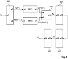
- the figure 8 is a block diagram of an example of implementation of the processing circuit 303 of the control device 300 of the figure 3 .
- the circuit 303 comprises a temporal filtering stage 801.
- the stage 801 includes an input a1 receiving the entire return signal S measured by the ultrasonic transducer 301, in particular during the ranges T1 and T2, following the emission of an excitation signal by the transducer, and two outputs a2 and a3 respectively supplying the return signal S (T1) measured by the transducer during the time range T1, and the return signal S (T1 + T2) measured by the transducer during the time range T1 + T2.
- Route 303 of the figure 8 furthermore comprises two stages FFT1 and FFT2 for calculating frequency transposed.
- the FFT1 stage has an input a4 connected to the output a2 of the stage 801, and the FFT2 stage has an input a5 connected to the output a3 of the stage 801.
- Each of the stages FFT1 and FFT2 is adapted to calculate a transposed into the frequency domain, for example a fast Fourier transform, of the time signal applied to its input.
- the FFT1 stage comprises an output a6 providing the transpose FFT (T1) of the signal S (T1), and an output a7 providing the transpose FFT (T1 + T2) of the signal S (T1 + T2).
- Route 303 of the figure 8 further comprises a stage 803 comprising two inputs a8 and a9 respectively connected to the output a6 of the stage FFT1 and to the output a7 of the stage FFT2.
- Stage 803 is suitable for generating the spectral signal R g representative of the frequency change in the overall reflection coefficient of the assembly.
- the stage 803 can for example divide the output signal FFT (T1 + T2) of the stage FFT2 by the output signal FFT (T1) of the stage FFT1.
- Stage 803 comprises an output a10 for supplying the signal R g .
- Route 303 of the figure 8 furthermore comprises a stage 805 for detecting resonance peaks, an input a11 of which is connected to the output a10 of the stage 803.
- the stage 805 is adapted to analyze the signal R g supplied by the stage 803 and to detect the signals. resonance peaks characteristic of this signal (peaks P1, P2, P3, P4, P5, P6, P6, P8, P9, P10 in the example of figure 5 ).
- Stage 805 includes an output a12 providing the frequency coordinates of the peaks detected.
- Route 303 of the figure 8 further comprises a stage 807 suitable for measuring the frequency difference ⁇ f between consecutive resonance peaks detected by stage 805.
- Stage 807 comprises an input a13 connected to the output a12 of stage 805, and an output a14 providing the measured and possibly averaged ⁇ f value.
- Route 303 of the figure 8 further comprises a stage 809 adapted to determine a value E representative of the adhesion energy between the two substrates of the assembly checked, from the frequency difference value ⁇ f supplied by the stage 807.
- the stage 809 comprises an input a15 connected to the output a14 of the stage 807, and an output a16 providing the value E.
- An advantage of the embodiments described in relation to the figures 3 to 8 is that they make it possible to carry out a non-destructive control of the quality of a bond between two substrates, and this including in the case where the two substrates are of the same nature and have surface roughness of very small dimensions at the interface between the two substrates.
- the embodiments described can however also be used to control assemblies in which the two substrates are made of different materials, and / or exhibit greater roughness at the interface between the two substrates. Indeed, the method described above remains applicable in the case where the return signal measured by the transducer in the range T2 comprises, in addition to the background echoes shown in figure 3 , one or more interface echoes.
- the transmission-reception phases above can be repeated a plurality of times, for example 200 to 600 times at a firing frequency (number of transmissions per second of the excitation signal) of the order of 1 kHz, so as to increase the signal-to-noise ratio of measurement.
- the signal analyzed by the processing device is for example an average of the return signals measured by the transducer during the successive transmission-reception phases.
- control method described above can be repeated a plurality of times, by moving the ultrasonic transducer parallel to the mean plane of the assembly of the substrates between two successive iterations, so as to obtain an image or map of the local adhesion energy between the two substrates.
- the resolution of this image will depend in particular on the surface of the assembly portion excited by the ultrasonic transducer at each iteration of the method, and on the displacement of the transducer relative to the assembly between two successive iterations of the method.
Landscapes
- Physics & Mathematics (AREA)
- General Physics & Mathematics (AREA)
- Pathology (AREA)
- Life Sciences & Earth Sciences (AREA)
- Chemical & Material Sciences (AREA)
- Analytical Chemistry (AREA)
- Biochemistry (AREA)
- General Health & Medical Sciences (AREA)
- Health & Medical Sciences (AREA)
- Immunology (AREA)
- Engineering & Computer Science (AREA)
- Signal Processing (AREA)
- Acoustics & Sound (AREA)
- Mathematical Physics (AREA)
- Spectroscopy & Molecular Physics (AREA)
- Algebra (AREA)
- Mathematical Analysis (AREA)
- Mathematical Optimization (AREA)
- Pure & Applied Mathematics (AREA)
- Investigating Or Analyzing Materials By The Use Of Ultrasonic Waves (AREA)
- Pressure Welding/Diffusion-Bonding (AREA)
Claims (12)
- Verfahren zum Steuern einer Anordnung aus einem ersten (W1) und einem zweiten (W2) Substrat, die jeweils eine vordere Oberfläche (A1, A2) und eine hintere Oberfläche (B1, B2) aufweisen, wobei die hintere Oberfläche (B1) des ersten Substrats (W1) mit der vorderen Oberfläche (A2) des zweiten Substrats (W2) verbunden bzw. verklebt ist, wobei das Verfahren die folgenden Schritte aufweist:a) Übertragen eines Anregungs-Ultraschallsignals in Richtung der Anordnung mittels eines Ultraschallwandlers (301), der auf der Seite der vorderen Oberfläche (A1) des ersten Substrats (W1) angeordnet ist;b) Messen eines Ultraschallrückkehrsignals, das mindestens ein Echo (EF1) des Anregungssignals aufweist, und zwar auf der hinteren Oberfläche (B2) des zweiten Substrats (W2) mit Hilfe des genannten Wandlers (301);c) Berechnen, mittels einer Verarbeitungsschaltung (303), eines Spektralsignals (Rg), das für die Frequenzvariation eines Gesamt-Reflexionskoeffizienten der Anordnung repräsentativ ist, der als das Verhältnis des in Schritt b) gemessenen Rückkehrsignals zu dem Anregungssignal definiert ist; undd) Ableiten von Informationen über die Qualität der Verbindung bzw. Verklebung zwischen dem ersten (W1) und dem zweiten (W2) Substrat, und zwar aus dem Spektralsignal (Rg) mit Hilfe der Verarbeitungsschaltung (303).
- Verfahren nach Anspruch 1, wobei der Schritt d) die folgenden Schritte aufweist:Erfassen einer Reihe von aufeinanderfolgenden Spitzen des Spektralsignals (Rg), die Resonanzen der Anordnung, die das erste (W1) und das zweite (W2) Substrat aufweist, entsprechen; undBestimmen des durchschnittlichen Häufigkeitsintervalls Δf zwischen zwei aufeinanderfolgenden Spitzen von jeweils ungeraden und geraden Ordnungszahlen oder von jeweils geraden und ungeraden Ordnungszahlen in der Reihe.
- Verfahren nach Anspruch 2, wobei der Schritt d) das Bestimmen eines für die Bindungsenergie zwischen dem ersten (W1) und dem zweiten (W2) Substrat repräsentativen Anhaftungswertes aus dem bestimmten durchschnittlichen Frequenzintervall Δf aufweist.
- Verfahren nach Anspruch 2 oder 3, wobei die Reihe von Spitzen mindestens 4 Spitzen aufweist.
- Verfahren nach einem der Ansprüche 1 bis 4, wobei das Rückkehrsignal mindestens zwei aufeinanderfolgende Echos (EF1, EF2, EF3) des Anregungssignals auf der hinteren Oberfläche (B2) des zweiten Substrats (W2) aufweist.
- Verfahren nach Anspruch 5, wobei das Rückkehrsignal drei aufeinanderfolgende Echos (EF1, EF2, EF3) des Anregungssignals auf der hinteren Oberfläche (B2) des zweiten Substrats (W2) aufweist.
- Verfahren nach einem der Ansprüche 1 bis 6, wobei:in Schritt b) das genannte Rückkehrsignal während zwei aufeinanderfolgender Zeitbereiche T1 und T2 gemessen wird, wobei der Bereich T1 nur ein Oberflächenecho (Es) des Anregungssignals aufweist, das direkt von der vorderen Oberfläche (A1) des ersten Substrats (W1) reflektiert wird, und der Bereich T2 das genannte mindestens eine Echo (EF1) des Anregungssignals auf der hinteren Oberfläche (B2) des zweiten Substrats (W2) aufweist; undin Schritt c) das berechnete Spektralsignal (Rg) mit dem Verhältnis einer Frequenzverschiebung des während des Bereichs T1+T2 gemessenen Rückkehrsignals zu einer Frequenzverschiebung des während des Bereichs T1 gemessenen Rückkehrsignals korreliert.
- Verfahren nach einem der Ansprüche 1 bis 7, wobei das Anregungs-Ultraschallsignal eine Frequenz im Bereich von 100 MHz bis 1 GHz hat.
- Verfahren nach einem der Ansprüche 1 bis 8, wobei die Dauer des Anregungs-Ultraschallsignals kürzer als 1 µs ist.
- Verfahren nach einem der Ansprüche 1 bis 9, wobei die Schritte a) bis d) mehrmals wiederholt werden, wobei der Ultraschallwandler (301) parallel zur Mittelebene der Anordnung zwischen zwei aufeinanderfolgenden Iterationen verschoben wird, um ein Bild oder eine Abbildung der Qualität der Verbindung bzw. Verklebung zwischen den beiden Substraten zu erhalten.
- Verfahren nach einem der Ansprüche 1 bis 10, wobei in Schritt a) das Anregungs-Ultraschallsignal unter einem senkrechten Einfall in Bezug auf die vordere Oberfläche (A1) des ersten Substrats (W1) abgestrahlt wird.
- Vorrichtung zum Steuern einer Anordnung, die ein erstes (W1) und ein zweites (W2) Substrat aufweist, die jeweils eine vordere Oberfläche (A1, A2) und eine hintere Oberfläche (B1, B2) aufweisen, wobei die hintere Oberfläche (B1) des ersten Substrats (W1) mit der vorderen Oberfläche (A2) des zweiten Substrats (W2) verbunden bzw. verklebt ist, wobei die Vorrichtung einen Ultraschallwandler (301) und eine Verarbeitungsvorrichtung (303) aufweist, die so konfiguriert sind, dass sie das Steuerverfahren nach einem der Ansprüche 1 bis 11 implementieren.
Applications Claiming Priority (2)
| Application Number | Priority Date | Filing Date | Title |
|---|---|---|---|
| FR1662258A FR3060121B1 (fr) | 2016-12-09 | 2016-12-09 | Procede et dispositif de controle d'un collage entre deux substrats |
| PCT/FR2017/053420 WO2018104666A1 (fr) | 2016-12-09 | 2017-12-06 | Procede et dispositif de controle d'un collage entre deux substrats |
Publications (2)
| Publication Number | Publication Date |
|---|---|
| EP3552008A1 EP3552008A1 (de) | 2019-10-16 |
| EP3552008B1 true EP3552008B1 (de) | 2020-11-11 |
Family
ID=57965974
Family Applications (1)
| Application Number | Title | Priority Date | Filing Date |
|---|---|---|---|
| EP17821687.5A Active EP3552008B1 (de) | 2016-12-09 | 2017-12-06 | Verfahren und vorrichtung zur prüfung einer verbindung zwischen zwei substraten |
Country Status (4)
| Country | Link |
|---|---|
| US (1) | US11054402B2 (de) |
| EP (1) | EP3552008B1 (de) |
| FR (1) | FR3060121B1 (de) |
| WO (1) | WO2018104666A1 (de) |
Families Citing this family (3)
| Publication number | Priority date | Publication date | Assignee | Title |
|---|---|---|---|---|
| WO2017149658A1 (ja) * | 2016-03-01 | 2017-09-08 | 三菱電機株式会社 | 超音波測定装置及び超音波測定方法 |
| US11467130B2 (en) | 2018-09-13 | 2022-10-11 | JANA Corporation | Apparatus and method for inspecting a fusion joint |
| US11280764B2 (en) * | 2019-08-29 | 2022-03-22 | The Boeing Company | Ultrasonic inspective device for simultaneous pulse echo and through transmission inspection |
Family Cites Families (2)
| Publication number | Priority date | Publication date | Assignee | Title |
|---|---|---|---|---|
| US5408881A (en) * | 1993-09-15 | 1995-04-25 | National Research Council Of Canada | High resolution ultrasonic interferometry for quantitative mondestructive characterization of interfacial adhesion in multilayer composites |
| GB0818383D0 (en) * | 2008-10-08 | 2008-11-12 | Qinetiq Ltd | Compposite evaluation |
-
2016
- 2016-12-09 FR FR1662258A patent/FR3060121B1/fr not_active Expired - Fee Related
-
2017
- 2017-12-06 WO PCT/FR2017/053420 patent/WO2018104666A1/fr not_active Ceased
- 2017-12-06 US US16/466,393 patent/US11054402B2/en not_active Expired - Fee Related
- 2017-12-06 EP EP17821687.5A patent/EP3552008B1/de active Active
Non-Patent Citations (1)
| Title |
|---|
| None * |
Also Published As
| Publication number | Publication date |
|---|---|
| FR3060121A1 (fr) | 2018-06-15 |
| US11054402B2 (en) | 2021-07-06 |
| EP3552008A1 (de) | 2019-10-16 |
| WO2018104666A1 (fr) | 2018-06-14 |
| FR3060121B1 (fr) | 2019-05-17 |
| US20190353623A1 (en) | 2019-11-21 |
Similar Documents
| Publication | Publication Date | Title |
|---|---|---|
| EP0904535B1 (de) | Verfahren und vorrichtung zur erfassung und lokalisierung einer reflektierenden schallquelle | |
| EP1562034B1 (de) | Verfahren zur Messung der Haftfestigkeit einer Beschichtung auf einem Substrat durch akustische Ankopplung eines Transducers mittels einer dünnen Schicht | |
| EP0129566B1 (de) | Ultraschallverfahren zum messen von spannungen in dazu geeigneten bolzen oder dgl. | |
| EP3552008B1 (de) | Verfahren und vorrichtung zur prüfung einer verbindung zwischen zwei substraten | |
| CA2543130C (fr) | Procede et dispositif de caracterisation d'un fluide | |
| EP3532832B1 (de) | Verfahren zur zerstörungsfreien prüfung einer verklebten anordnung mittels ultraschall | |
| EP2271928B1 (de) | Verfahren und vorrichtung für nicht destruktive ultraschallprüfung der porosität eines teils aus verbundstoff | |
| JP3864940B2 (ja) | 膜強度測定方法、膜を有する被測定物の良否判定方法 | |
| EP1998175B1 (de) | Ultraschallvorhersage über die Deformation eines Werkstücks | |
| EP1893976B1 (de) | Vorrichtung und verfahren zur charakterisierung einer struktur mittels wellenlängeneffekt in einem photoakustischen system | |
| WO2024074252A1 (fr) | Procede d'imagerie ultrasonore par transformee de fourier multidimensionnelle a l'aide de deux transducteurs multielements distincts | |
| EP3044580B1 (de) | Verfahren zur zerstörungsfreien ultraschallprüfung eines bauteils mittels echoanalyse | |
| FR3044770A1 (fr) | Procede de controle d'un objet par ultrasons | |
| EP2861977B1 (de) | Zerstörungsfreie ultraschallprüfung von verbundstrukturen | |
| WO2025124836A1 (fr) | Procédé de détection d'un défaut dans une structure à l'aide d'ondes mécaniques hautes fréquences | |
| EP4308916B1 (de) | Laserschockverfahren | |
| WO2022238665A1 (fr) | Procédé de mesure d'un module d'élasticité par génération laser d'ondes de surface à une interface matériau/liquide | |
| CA3041166C (fr) | Procede de controle non destructif par ultrasons d'un assemblage colle | |
| EP4664085A1 (de) | System zur steuerung der spannung einer befestigung in einer anordnung und steuerungsverfahren dafür | |
| EP4697011A1 (de) | Verfahren und prüfstand zur adhäsionsprüfung der schnittstelle zwischen zwei materialien | |
| WO2015193604A1 (fr) | Procede de controle non destructif et sans contact d'un objet ayant une surface complexe par sondage, programme d'ordinateur et dispositif de sondage correspondants | |
| EP4053553A1 (de) | Verfahren zur erkennung von rissen in einem durch additive fertigung hergestellten teil aus aluminiumlegierung | |
| EP3137875A1 (de) | Vorrichtung zur charakterisierung einer schnittstelle einer struktur und entsprechende vorrichtung | |
| FR3013454A1 (fr) | Procede de caracterisation d'une piece par ultrasons | |
| FR3013455A1 (fr) | Procede de controle par ultrasons en immersion d'un assemblage multi-materiaux, notamment composite - nid d'abeille en aramide |
Legal Events
| Date | Code | Title | Description |
|---|---|---|---|
| STAA | Information on the status of an ep patent application or granted ep patent |
Free format text: STATUS: UNKNOWN |
|
| STAA | Information on the status of an ep patent application or granted ep patent |
Free format text: STATUS: THE INTERNATIONAL PUBLICATION HAS BEEN MADE |
|
| PUAI | Public reference made under article 153(3) epc to a published international application that has entered the european phase |
Free format text: ORIGINAL CODE: 0009012 |
|
| STAA | Information on the status of an ep patent application or granted ep patent |
Free format text: STATUS: REQUEST FOR EXAMINATION WAS MADE |
|
| 17P | Request for examination filed |
Effective date: 20190627 |
|
| AK | Designated contracting states |
Kind code of ref document: A1 Designated state(s): AL AT BE BG CH CY CZ DE DK EE ES FI FR GB GR HR HU IE IS IT LI LT LU LV MC MK MT NL NO PL PT RO RS SE SI SK SM TR |
|
| AX | Request for extension of the european patent |
Extension state: BA ME |
|
| DAV | Request for validation of the european patent (deleted) | ||
| DAX | Request for extension of the european patent (deleted) | ||
| GRAP | Despatch of communication of intention to grant a patent |
Free format text: ORIGINAL CODE: EPIDOSNIGR1 |
|
| STAA | Information on the status of an ep patent application or granted ep patent |
Free format text: STATUS: GRANT OF PATENT IS INTENDED |
|
| INTG | Intention to grant announced |
Effective date: 20200708 |
|
| GRAS | Grant fee paid |
Free format text: ORIGINAL CODE: EPIDOSNIGR3 |
|
| GRAA | (expected) grant |
Free format text: ORIGINAL CODE: 0009210 |
|
| STAA | Information on the status of an ep patent application or granted ep patent |
Free format text: STATUS: THE PATENT HAS BEEN GRANTED |
|
| AK | Designated contracting states |
Kind code of ref document: B1 Designated state(s): AL AT BE BG CH CY CZ DE DK EE ES FI FR GB GR HR HU IE IS IT LI LT LU LV MC MK MT NL NO PL PT RO RS SE SI SK SM TR |
|
| REG | Reference to a national code |
Ref country code: GB Ref legal event code: FG4D Free format text: NOT ENGLISH |
|
| REG | Reference to a national code |
Ref country code: CH Ref legal event code: EP |
|
| REG | Reference to a national code |
Ref country code: AT Ref legal event code: REF Ref document number: 1333973 Country of ref document: AT Kind code of ref document: T Effective date: 20201115 |
|
| REG | Reference to a national code |
Ref country code: DE Ref legal event code: R096 Ref document number: 602017027516 Country of ref document: DE |
|
| REG | Reference to a national code |
Ref country code: IE Ref legal event code: FG4D Free format text: LANGUAGE OF EP DOCUMENT: FRENCH |
|
| REG | Reference to a national code |
Ref country code: NL Ref legal event code: MP Effective date: 20201111 |
|
| REG | Reference to a national code |
Ref country code: AT Ref legal event code: MK05 Ref document number: 1333973 Country of ref document: AT Kind code of ref document: T Effective date: 20201111 |
|
| PG25 | Lapsed in a contracting state [announced via postgrant information from national office to epo] |
Ref country code: NO Free format text: LAPSE BECAUSE OF FAILURE TO SUBMIT A TRANSLATION OF THE DESCRIPTION OR TO PAY THE FEE WITHIN THE PRESCRIBED TIME-LIMIT Effective date: 20210211 Ref country code: GR Free format text: LAPSE BECAUSE OF FAILURE TO SUBMIT A TRANSLATION OF THE DESCRIPTION OR TO PAY THE FEE WITHIN THE PRESCRIBED TIME-LIMIT Effective date: 20210212 Ref country code: RS Free format text: LAPSE BECAUSE OF FAILURE TO SUBMIT A TRANSLATION OF THE DESCRIPTION OR TO PAY THE FEE WITHIN THE PRESCRIBED TIME-LIMIT Effective date: 20201111 Ref country code: PT Free format text: LAPSE BECAUSE OF FAILURE TO SUBMIT A TRANSLATION OF THE DESCRIPTION OR TO PAY THE FEE WITHIN THE PRESCRIBED TIME-LIMIT Effective date: 20210311 Ref country code: FI Free format text: LAPSE BECAUSE OF FAILURE TO SUBMIT A TRANSLATION OF THE DESCRIPTION OR TO PAY THE FEE WITHIN THE PRESCRIBED TIME-LIMIT Effective date: 20201111 |
|
| PG25 | Lapsed in a contracting state [announced via postgrant information from national office to epo] |
Ref country code: LV Free format text: LAPSE BECAUSE OF FAILURE TO SUBMIT A TRANSLATION OF THE DESCRIPTION OR TO PAY THE FEE WITHIN THE PRESCRIBED TIME-LIMIT Effective date: 20201111 Ref country code: IS Free format text: LAPSE BECAUSE OF FAILURE TO SUBMIT A TRANSLATION OF THE DESCRIPTION OR TO PAY THE FEE WITHIN THE PRESCRIBED TIME-LIMIT Effective date: 20210311 Ref country code: PL Free format text: LAPSE BECAUSE OF FAILURE TO SUBMIT A TRANSLATION OF THE DESCRIPTION OR TO PAY THE FEE WITHIN THE PRESCRIBED TIME-LIMIT Effective date: 20201111 Ref country code: SE Free format text: LAPSE BECAUSE OF FAILURE TO SUBMIT A TRANSLATION OF THE DESCRIPTION OR TO PAY THE FEE WITHIN THE PRESCRIBED TIME-LIMIT Effective date: 20201111 Ref country code: BG Free format text: LAPSE BECAUSE OF FAILURE TO SUBMIT A TRANSLATION OF THE DESCRIPTION OR TO PAY THE FEE WITHIN THE PRESCRIBED TIME-LIMIT Effective date: 20210211 Ref country code: AT Free format text: LAPSE BECAUSE OF FAILURE TO SUBMIT A TRANSLATION OF THE DESCRIPTION OR TO PAY THE FEE WITHIN THE PRESCRIBED TIME-LIMIT Effective date: 20201111 |
|
| REG | Reference to a national code |
Ref country code: LT Ref legal event code: MG9D |
|
| PG25 | Lapsed in a contracting state [announced via postgrant information from national office to epo] |
Ref country code: HR Free format text: LAPSE BECAUSE OF FAILURE TO SUBMIT A TRANSLATION OF THE DESCRIPTION OR TO PAY THE FEE WITHIN THE PRESCRIBED TIME-LIMIT Effective date: 20201111 |
|
| PG25 | Lapsed in a contracting state [announced via postgrant information from national office to epo] |
Ref country code: SK Free format text: LAPSE BECAUSE OF FAILURE TO SUBMIT A TRANSLATION OF THE DESCRIPTION OR TO PAY THE FEE WITHIN THE PRESCRIBED TIME-LIMIT Effective date: 20201111 Ref country code: RO Free format text: LAPSE BECAUSE OF FAILURE TO SUBMIT A TRANSLATION OF THE DESCRIPTION OR TO PAY THE FEE WITHIN THE PRESCRIBED TIME-LIMIT Effective date: 20201111 Ref country code: SM Free format text: LAPSE BECAUSE OF FAILURE TO SUBMIT A TRANSLATION OF THE DESCRIPTION OR TO PAY THE FEE WITHIN THE PRESCRIBED TIME-LIMIT Effective date: 20201111 Ref country code: EE Free format text: LAPSE BECAUSE OF FAILURE TO SUBMIT A TRANSLATION OF THE DESCRIPTION OR TO PAY THE FEE WITHIN THE PRESCRIBED TIME-LIMIT Effective date: 20201111 Ref country code: CZ Free format text: LAPSE BECAUSE OF FAILURE TO SUBMIT A TRANSLATION OF THE DESCRIPTION OR TO PAY THE FEE WITHIN THE PRESCRIBED TIME-LIMIT Effective date: 20201111 Ref country code: LT Free format text: LAPSE BECAUSE OF FAILURE TO SUBMIT A TRANSLATION OF THE DESCRIPTION OR TO PAY THE FEE WITHIN THE PRESCRIBED TIME-LIMIT Effective date: 20201111 |
|
| REG | Reference to a national code |
Ref country code: CH Ref legal event code: PL |
|
| REG | Reference to a national code |
Ref country code: DE Ref legal event code: R097 Ref document number: 602017027516 Country of ref document: DE |
|
| PG25 | Lapsed in a contracting state [announced via postgrant information from national office to epo] |
Ref country code: DK Free format text: LAPSE BECAUSE OF FAILURE TO SUBMIT A TRANSLATION OF THE DESCRIPTION OR TO PAY THE FEE WITHIN THE PRESCRIBED TIME-LIMIT Effective date: 20201111 Ref country code: MC Free format text: LAPSE BECAUSE OF FAILURE TO SUBMIT A TRANSLATION OF THE DESCRIPTION OR TO PAY THE FEE WITHIN THE PRESCRIBED TIME-LIMIT Effective date: 20201111 |
|
| REG | Reference to a national code |
Ref country code: BE Ref legal event code: MM Effective date: 20201231 |
|
| PLBE | No opposition filed within time limit |
Free format text: ORIGINAL CODE: 0009261 |
|
| STAA | Information on the status of an ep patent application or granted ep patent |
Free format text: STATUS: NO OPPOSITION FILED WITHIN TIME LIMIT |
|
| 26N | No opposition filed |
Effective date: 20210812 |
|
| PG25 | Lapsed in a contracting state [announced via postgrant information from national office to epo] |
Ref country code: IE Free format text: LAPSE BECAUSE OF NON-PAYMENT OF DUE FEES Effective date: 20201206 Ref country code: AL Free format text: LAPSE BECAUSE OF FAILURE TO SUBMIT A TRANSLATION OF THE DESCRIPTION OR TO PAY THE FEE WITHIN THE PRESCRIBED TIME-LIMIT Effective date: 20201111 Ref country code: NL Free format text: LAPSE BECAUSE OF FAILURE TO SUBMIT A TRANSLATION OF THE DESCRIPTION OR TO PAY THE FEE WITHIN THE PRESCRIBED TIME-LIMIT Effective date: 20201111 Ref country code: LU Free format text: LAPSE BECAUSE OF NON-PAYMENT OF DUE FEES Effective date: 20201206 Ref country code: IT Free format text: LAPSE BECAUSE OF FAILURE TO SUBMIT A TRANSLATION OF THE DESCRIPTION OR TO PAY THE FEE WITHIN THE PRESCRIBED TIME-LIMIT Effective date: 20201111 |
|
| PG25 | Lapsed in a contracting state [announced via postgrant information from national office to epo] |
Ref country code: LI Free format text: LAPSE BECAUSE OF NON-PAYMENT OF DUE FEES Effective date: 20201231 Ref country code: SI Free format text: LAPSE BECAUSE OF FAILURE TO SUBMIT A TRANSLATION OF THE DESCRIPTION OR TO PAY THE FEE WITHIN THE PRESCRIBED TIME-LIMIT Effective date: 20201111 Ref country code: CH Free format text: LAPSE BECAUSE OF NON-PAYMENT OF DUE FEES Effective date: 20201231 |
|
| PG25 | Lapsed in a contracting state [announced via postgrant information from national office to epo] |
Ref country code: ES Free format text: LAPSE BECAUSE OF FAILURE TO SUBMIT A TRANSLATION OF THE DESCRIPTION OR TO PAY THE FEE WITHIN THE PRESCRIBED TIME-LIMIT Effective date: 20201111 |
|
| PG25 | Lapsed in a contracting state [announced via postgrant information from national office to epo] |
Ref country code: IS Free format text: LAPSE BECAUSE OF FAILURE TO SUBMIT A TRANSLATION OF THE DESCRIPTION OR TO PAY THE FEE WITHIN THE PRESCRIBED TIME-LIMIT Effective date: 20210311 Ref country code: TR Free format text: LAPSE BECAUSE OF FAILURE TO SUBMIT A TRANSLATION OF THE DESCRIPTION OR TO PAY THE FEE WITHIN THE PRESCRIBED TIME-LIMIT Effective date: 20201111 Ref country code: MT Free format text: LAPSE BECAUSE OF FAILURE TO SUBMIT A TRANSLATION OF THE DESCRIPTION OR TO PAY THE FEE WITHIN THE PRESCRIBED TIME-LIMIT Effective date: 20201111 Ref country code: CY Free format text: LAPSE BECAUSE OF FAILURE TO SUBMIT A TRANSLATION OF THE DESCRIPTION OR TO PAY THE FEE WITHIN THE PRESCRIBED TIME-LIMIT Effective date: 20201111 |
|
| PG25 | Lapsed in a contracting state [announced via postgrant information from national office to epo] |
Ref country code: MK Free format text: LAPSE BECAUSE OF FAILURE TO SUBMIT A TRANSLATION OF THE DESCRIPTION OR TO PAY THE FEE WITHIN THE PRESCRIBED TIME-LIMIT Effective date: 20201111 |
|
| PG25 | Lapsed in a contracting state [announced via postgrant information from national office to epo] |
Ref country code: BE Free format text: LAPSE BECAUSE OF NON-PAYMENT OF DUE FEES Effective date: 20201231 |
|
| PGFP | Annual fee paid to national office [announced via postgrant information from national office to epo] |
Ref country code: GB Payment date: 20231221 Year of fee payment: 7 |
|
| PGFP | Annual fee paid to national office [announced via postgrant information from national office to epo] |
Ref country code: FR Payment date: 20231218 Year of fee payment: 7 Ref country code: DE Payment date: 20231219 Year of fee payment: 7 |
|
| REG | Reference to a national code |
Ref country code: DE Ref legal event code: R119 Ref document number: 602017027516 Country of ref document: DE |
|
| GBPC | Gb: european patent ceased through non-payment of renewal fee |
Effective date: 20241206 |
|
| PG25 | Lapsed in a contracting state [announced via postgrant information from national office to epo] |
Ref country code: DE Free format text: LAPSE BECAUSE OF NON-PAYMENT OF DUE FEES Effective date: 20250701 |
|
| PG25 | Lapsed in a contracting state [announced via postgrant information from national office to epo] |
Ref country code: GB Free format text: LAPSE BECAUSE OF NON-PAYMENT OF DUE FEES Effective date: 20241206 |
|
| PG25 | Lapsed in a contracting state [announced via postgrant information from national office to epo] |
Ref country code: FR Free format text: LAPSE BECAUSE OF NON-PAYMENT OF DUE FEES Effective date: 20241231 |