EP3551912B1 - Ölabstreifkolbenring - Google Patents
Ölabstreifkolbenring Download PDFInfo
- Publication number
- EP3551912B1 EP3551912B1 EP17803769.3A EP17803769A EP3551912B1 EP 3551912 B1 EP3551912 B1 EP 3551912B1 EP 17803769 A EP17803769 A EP 17803769A EP 3551912 B1 EP3551912 B1 EP 3551912B1
- Authority
- EP
- European Patent Office
- Prior art keywords
- bearing surface
- web
- piston ring
- oil scraper
- counter
- Prior art date
- Legal status (The legal status is an assumption and is not a legal conclusion. Google has not performed a legal analysis and makes no representation as to the accuracy of the status listed.)
- Active
Links
Images
Classifications
-
- F—MECHANICAL ENGINEERING; LIGHTING; HEATING; WEAPONS; BLASTING
- F16—ENGINEERING ELEMENTS AND UNITS; GENERAL MEASURES FOR PRODUCING AND MAINTAINING EFFECTIVE FUNCTIONING OF MACHINES OR INSTALLATIONS; THERMAL INSULATION IN GENERAL
- F16J—PISTONS; CYLINDERS; SEALINGS
- F16J9/00—Piston-rings, e.g. non-metallic piston-rings, seats therefor; Ring sealings of similar construction
- F16J9/06—Piston-rings, e.g. non-metallic piston-rings, seats therefor; Ring sealings of similar construction using separate springs or elastic elements expanding the rings; Springs therefor ; Expansion by wedging
- F16J9/061—Piston-rings, e.g. non-metallic piston-rings, seats therefor; Ring sealings of similar construction using separate springs or elastic elements expanding the rings; Springs therefor ; Expansion by wedging using metallic coiled or blade springs
- F16J9/062—Coiled spring along the entire circumference
-
- F—MECHANICAL ENGINEERING; LIGHTING; HEATING; WEAPONS; BLASTING
- F16—ENGINEERING ELEMENTS AND UNITS; GENERAL MEASURES FOR PRODUCING AND MAINTAINING EFFECTIVE FUNCTIONING OF MACHINES OR INSTALLATIONS; THERMAL INSULATION IN GENERAL
- F16J—PISTONS; CYLINDERS; SEALINGS
- F16J9/00—Piston-rings, e.g. non-metallic piston-rings, seats therefor; Ring sealings of similar construction
- F16J9/12—Details
- F16J9/20—Rings with special cross-section; Oil-scraping rings
- F16J9/206—One-piece oil-scraping rings
Definitions
- the invention relates to an oil control piston ring for an internal combustion engine.
- a compression piston ring for an internal combustion engine including a running surface formed by two webs, upper and lower flank surfaces and an inner circumferential surface, the lower web running at least partially parallel to a counter surface and the upper web being designed as a nose minute element.
- the lower web can be convex.
- the DE 100 02 282 C1 discloses a method of making an oil control piston ring and an oil control piston ring.
- the oil control piston ring contains two webs which are provided with a hump-like profile, on which a wear-resistant coating is provided.
- An oil control piston ring comprising an annular body and two radially outer raceways on the annular body, which are arranged one behind the other with respect to the direction of travel of the piston and are spaced apart from one another by an outer recess, each raceway having two wiper lips and a wear protection coating provided on each wiper lip is.
- the DE 100 18 322 C1 an oil control piston ring with two, relative to the axial height of the ring, asymmetrical webs can be seen, whereby the web facing the compression chamber is provided approximately at the middle axial height of the ring, and in the ring back area, a spring provided approximately in the center of the ring, is arranged.
- the DE 10 2009 036 240 A1 discloses a compression ring comprising a tread area, upper and lower flanks and an inner circumferential surface, the tread area being provided with a profiling.
- the profiling includes, viewed over the axial height of the running surface area, spaced approximately convexly crowned, each having an apex, which enclose a groove of predeterminable depth between them, the compression piston ring having a centroid which is in the axial direction in a plane between the apexes lies.
- the invention is based on the object of providing an oil control piston ring for an internal combustion engine which effects an optimized oil control behavior both in the upward and in the downward stroke of the piston.
- an oil control piston ring for an internal combustion engine with two webs arranged axially one above the other in the area of its running surface, both webs in contact with a counter-running surface forming the running surface and the webs being provided on the opposite-running surface side with a profile which, if necessary, has an at least partial coating,
- Both webs are provided with different web geometries in such a way that the lower web takes over the predominant part of the wiping effect in the downward stroke and the upper web essentially floats on a residual oil film on the counter surface during the upward stroke, whereby the upper web, starting from its upper flank, is conical runs in the direction of the mating surface and then over a portion of the web height approximately parallel to the mating surface and is then provided with an asymmetrically convex tread profile at least over a portion of the height of the web.
- the lower web serves a maximum oil wiping behavior downwards, while the upper web is designed for a slight upward oil pushing.
- the lower web is advantageously provided with a hump-like profile which is arranged on the opposite surface side, advantageously in the lower region of the lower web.
- the entire web forming the running surface is advantageously provided on the running surface side with a wear-resistant coating, which can be formed, for example, by a PVD or CVD layer.
- a wear-resistant coating which can be formed, for example, by a PVD or CVD layer.
- Alternative layers based on chromium or the like are also conceivable here.
- the upper web starting from its upper flank, runs conically in the direction of the counter surface and then runs approximately parallel to the counter surface over part of the web height and is then provided with an asymmetrically convex tread profile at least over a partial region of the web height of the upper web.
- a wear-resistant coating at least on the running surface side, which, if necessary, can also be designed as a PVD or CVD layer.
- the wear-resistant coating of the upper web is rounded, in such a way that a gap is created that is open at the top. This provision promotes the floating of the upper web on the residual oil film of the counter surface.
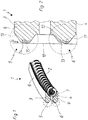
- Figure 1 shows an oil control piston ring 1, which is in operative connection with a spring element 2.
- the oil control piston ring 1 contains two webs 3, 4, which form running surfaces 5, 6 in the area of a counter surface, not shown. Oil drainage bores 7 are located between the webs 3, 4.
- the oil control piston ring 1 has upper 8 and lower flanks 9.
- FIG Figure 2 shows an enlarged view of the webs 3, 4 and the running surfaces 5, 6 of the oil control piston ring 1 according to FIG Figure 1 .
- the two webs 3, 4 are designed with different web geometries at the top and bottom, the web 3 forming the upper web and the web 4 forming the lower web.
- the counter surface 10 is also indicated, which can be formed, for example, by a cylinder wall.
- a hump-like profile 11 is provided in the region of the lower web 4, while the remaining web region 12 runs approximately parallel to the counter-running surface 10.
- a wear-resistant layer in the form of a PVD layer 13 is applied to the entire running surface 6 of the web 4, which follows the geometric contour of the web 4 on the running surface side.
- the upper web 3 is provided on the opposite surface side - starting from its upper flank 8 - initially with a section 13 which tapers conically in the direction of the opposite surface 10 and which merges into an area 14 running approximately parallel to the opposite surface 10. According to the invention, the upper web is then provided with an asymmetrically spherical running surface profile at least over a portion of the web height.
- the web 3 is also provided in the area of its running surface 5 with a wear-resistant coating, for example a PVD layer 15, which is processed in such a way that it is provided in a rounded shape with the formation of a gap 16.
- the lower web 4 effects maximum oil wiping behavior downwards, while the upper web 3 is provided for the least possible oil pushing upwards.
Landscapes
- Engineering & Computer Science (AREA)
- General Engineering & Computer Science (AREA)
- Mechanical Engineering (AREA)
- Pistons, Piston Rings, And Cylinders (AREA)
- Tires In General (AREA)
Description
- Die Erfindung betrifft einen Ölabstreifkolbenring für eine Brennkraftmaschine.
- Der
DE 10 2009 009 744 A1 ist ein Kompressionskolbenring für eine Brennkraftmaschine zu entnehmen, beinhaltend eine, durch zwei Stege gebildete Lauffläche, obere und untere Flankenflächen sowie eine innere Umfangsfläche, wobei der untere Steg zumindest partiell parallel zu einer Gegenlauffläche verläuft und der obere Steg als Nasenminutenelement ausgebildet ist. Der untere Steg kann ballig ausgebildet sein. - Die
DE 100 02 282 C1 offenbart ein Verfahren zur Herstellung eines Ölabstreifkolbenrings sowie einen Ölabstreifkolbenring. Der Ölabstreifkolbenring beinhaltet zwei Stege, die mit einem höckerartigen Profil versehen sind, aufweichen ein verschleißfester Überzug vorgesehen ist. - In der
DE 10 2010 001 434 B4 wird ein Ölabstreifkolbenring beschrieben, umfassend einen Ringkörper sowie zwei radial äußere Laufstege auf dem Ringkörper, die in Bezug auf die Laufrichtung des Kolbens hintereinander angeordnet und durch eine äußere Vertiefung voneinander beabstandet sind, wobei jeder Laufsteg jeweils zwei Abstreiflippen aufweist und auf jeder Abstreiflippe eine Verschleißschutzbeschichtung vorgesehen ist. - Der
DE 100 18 322 C1 ist ein Ölabstreifkolbenring mit zwei, bezogen auf die axiale Bauhöhe des Ringes, asymetrischen Stegen zu entnehmen, wobei der, dem Kompressionsraum zugewandte Steg, etwa auf mittlerer axialer Bauhöhe des Ringes, vorgesehen ist, und wobei im Ringrückenbereich, eine etwa in Ringmitte vorgesehene Feder, angeordnet ist. - Die
DE 10 2009 036 240 A1 offenbart einen Kompressionsring, beinhaltend einen Laufflächenbereich, obere und untere Flanken sowie eine innere Umfangsfläche, wobei der Laufflächenbereich mit einer Profilierung versehen ist. Die Profilierung beinhaltet, über die axiale Höhe des Laufflächenbereichs gesehen, von einander beabstandete, etwa konvex ballig ausgebildete, jeweils einen Scheitelpunkt aufweisende Abschnitte, die zwischen sich eine Nut vorgebbarerTiefe einschließen, wobei der Kompressionskolbenring einen Flächenschwerpunkt aufweist, der in axialer Richtung in einer Ebene zwischen den Scheitelpunkten liegt. - Der Erfindung liegt die Aufgabe zugrunde, einen Ölabstreifkolbenring für eine Brennkraftmaschine bereitzustellen, der ein optimiertes Ölabstreifverhalten sowohl im Auf- als auch im Abwärtshub des Kolbens bewirkt.
- Diese Aufgabe wird gelöst durch einen Ölabstreifkolbenring für eine Brennkraftmaschine mit zwei axial übereinander angeordneten Stegen im Bereich seiner Lauffläche, wobei beide Stege in Kontakt mit einer Gegenlauffläche die Lauffläche bilden und die Stege gegenlaufflächenseitig mit einem Profil versehen sind, das bedarfsweise eine zumindest partielle Beschichtung aufweist, wobei beide Stege dergestalt mit unterschiedlichen Steggeometrien versehen sind, dass der untere Steg den überwiegenden Anteil der Abstreifwirkung im Abwärtshub übernimmt und der obere Steg beim Aufwärtshub im Wesentlichen auf einem Restölfilm auf der Gegenlauffläche aufschwimmt, wobei der obere Steg, ausgehend von seiner oberen Flanke, konisch in Richtung der Gegenlauffläche und anschließend über einen Teilbereich der Steghöhe etwa parallel zur Gegenlauffläche verläuft und anschließend zumindest über einen Teilbereich der Steghöhe mit einem asymmetrisch balligen Laufflächenprofil versehen ist.
- Vorteilhafte Weiterbildungen des Erfindungsgegenstandes sind den Unteransprüchen zu entnehmen.
- Infolge der vorgeschlagenen Geometrie der beiden Laufflächenstege dient der untere Steg einem maximalen Ölabstreifverhalten nach unten, während der obere Steg für ein geringes Ölschieben nach oben ausgebildet ist.
- Der untere Steg ist vorteilhafterweise mit einem höckerartigen Profil versehen, das gegenlaufflächenseitig, vorteilhafterweise im unteren Bereich des unteren Steges, angeordnet ist.
- Vorteilhafterweise ist der gesamte, die Lauffläche bildende Steg laufflächenseitig mit einer verschleißfesten Beschichtung versehen, die beispielsweise durch eine PVD- oder CVD-Schicht gebildet sein kann. Alternative Schichten auf Basis von Chrom oder dergleichen sind hier ebenfalls denkbar.
- Erfindungsgemäß verläuft der obere Steg, ausgehend von seiner oberen Flanke, konisch in Richtung der Gegenlauffläche und verläuft anschließend über einen Teilbereich der Steghöhe etwa parallel zur Gegenlauffläche und ist anschließend zumindest über einen Teilbereich der Steghöhe des oberen Steges mit einem asymmetrisch balligen Laufflächenprofil versehen. Auch hier kann es sinnvoll sein, diejenigen, die Lauffläche bildenden Steganteile zumindest laufflächenseitig mit einer verschleißfesten Beschichtung zu versehen, die bedarfsweise ebenfalls als PVD- oder CVD-Schicht ausgebildet sein kann.
- Es ist ebenfalls denkbar, alternative Beschichtungen auf Basis von Chrom oder dergleichen vorzusehen.
- Von Vorteil ist, wenn die verschleißfeste Beschichtung des oberen Stegs gerundet ausgebildet wird, dergestalt, dass ein nach oben offener Spalt entsteht. Durch diese Maßgabe wird das Aufschwimmen des oberen Steges auf dem Restölfilm der Gegenlauffläche gefördert.
- Der Erfindungsgegenstand ist anhand eines Ausführungsbeispiels in der Zeichnung dargestellt und wird wie folgt beschrieben. Es zeigen:
- Figur 1
- Prinzipskizze eines Ölabstreifkolbenrings;
- Figur 2
- Teildarstellung der Stege des Kolbenrings gemäß
Figur 1 in vergrößerter Ansicht, wobei die Geometrie des oberen Stegs nicht erfindungsgemäß ausgeführt ist. -
Figur 1 zeigt einen Ölabstreifkolbenring 1, der in Wirkverbindung mit einem Federelement 2 steht. Der Ölabstreifkolbenring 1 beinhaltet zwei Stege 3,4, die im Bereich einer nicht dargestellten Gegenlauffläche Laufflächen 5,6 bilden. Zwischen den Stegen 3,4 befinden sich Ölablaufbohrungen 7. Der Ölabstreifkolbenring 1 weist obere 8 und untere Flanken 9. -
Figur 2 zeigt in vergrößerter Darstellung die Stege 3,4 sowie die Laufflächen 5,6 des Ölabstreifkolbenrings 1 gemäßFigur 1 . Die beiden Stege 3,4 sind mit unterschiedlichen Steggeometrien oben und unten ausgeführt, wobei der Steg 3 den oberen Steg und der Steg 4 den unteren Steg bildet. InFigur 2 ist auch die Gegenlauffläche 10 angedeutet, die beispielsweise durch eine Zylinderwand gebildet sein kann. Im Bereich des unteren Steges 4 ist ein höckerartiges Profil 11 vorgesehen, während der verbleibende Stegbereich 12 etwa parallel zur Gegenlauffläche 10 verläuft. Auf der gesamten Lauffläche 6 des Steges 4 ist in diesem Beispiel eine verschleißfeste Schicht in Form einer PVD-Schicht 13 aufgebracht, die laufflächenseitig der geometrischen Kontur des Steges 4 folgt. - Der obere Steg 3 ist gegenlaufflächenseitig - ausgehend von seiner oberen Flanke 8 - zunächst mit einem konisch sich in Richtung der Gegenlauffläche 10 verjüngenden Abschnitt 13 - versehen, der in einen etwa parallel zur Gegenlauffläche 10 verlaufenden Bereich 14 übergeht. Erfindungsgemäß ist der obere Steg anschließend zumindest über einen Teilbereich der Steghöhe mit einem asymmetrisch balligen Laufflächenprofil versehen. In Analogie zum Steg 4 ist auch der Steg 3 im Bereich seiner Lauffläche 5 mit einer verschleißfesten Beschichtung, beispielsweise einer PVD-Schicht 15, versehen, die dergestalt bearbeitet ist, dass sie unter Bildung eines Spaltes 16 in gerundeter Form vorgesehen ist.
- Infolge der unterschiedlichen geometrischen Stegausführungen bewirkt der untere Steg 4 ein maximales Ölabstreifverhalten nach unten, während der obere Steg 3 für ein geringstmögliches Ölschieben nach oben vorgesehen ist.
Claims (8)
- Ölabstreifkolbenring für eine Brennkraftmaschine mit zwei axial übereinander angeordneten Stegen (3,4) im Bereich seiner Lauffläche (5,6), wobei beide Stege (3,4) in Kontakt mit einer Gegenlauffläche (10) die Lauffläche (5,6) bilden und die Stege (3,4) gegenlaufflächenseitig mit einem Profil (11,13,14) versehen sind, das bedarfsweise eine zumindest partielle Beschichtung (13,15) aufweist, wobei beide Stege (3,4) dergestalt mit unterschiedlichen Steggeometrien versehen sind, dass der untere Steg (4) den überwiegenden Anteil der Abstreifwirkung im Abwärtshub übernimmt und der obere Steg (3) beim Aufwärtshub im Wesentlichen auf einem Restölfilm auf der Gegenlauffläche (10) aufschwimmt, dadurch gekennzeichnet, dass der obere Steg (3), ausgehend von seiner oberen Flanke (8), konisch in Richtung der Gegenlauffläche (10) und anschließend über einen Teilbereich der Steghöhe etwa parallel zur Gegenlauffläche (10) verläuft und anschließend zumindest über einen Teilbereich der Steghöhe mit einem asymmetrisch balligen Laufflächenprofil versehen ist.
- Ölabstreifkolbenring nach Anspruch 1, dadurch gekennzeichnet, dass der untere Steg (4) mit einem höckerartigen Profil (11) versehen ist.
- Ölabstreifkolbenring nach Anspruch 2, dadurch gekennzeichnet, dass das höckerartige Profil (11) gegenlaufflächenseitig im unteren Bereich des unteren Steges (4) vorgesehen ist.
- Ölabstreifkolbenring nach einem der Ansprüche 1 bis 3, dadurch gekennzeichnet, dass der gesamte, die Lauffläche (6) bildende untere Steg (4) laufflächenseitig mit einer verschleißfesten Beschichtung (13) versehen ist.
- Ölabstreifkolbenring nach Anspruch 4, dadurch gekennzeichnet, dass die Beschichtung (13) durch eine PVD- oder CVD-Schicht gebildet ist.
- Ölabstreifkolbenring nach einem der Ansprüche 1 bis 5, dadurch gekennzeichnet, dass der gesamte die Lauffläche (5) bildende obere Steg (3) laufflächenseitig mit einer verschleißfesten Beschichtung (15) versehen ist.
- Ölabstreifkolbenring nach Anspruch 6, dadurch gekennzeichnet, dass die Beschichtung (15) durch eine PVD- oder CVD-Schicht gebildet ist.
- Ölabstreifkolbenring nach einem der Ansprüche 1 bis 7, dadurch gekennzeichnet, dass die verschleißfeste Beschichtung (15) dergestalt gerundet ausgebildet ist, dass ein nach oben offener Spalt (16) entsteht.
Applications Claiming Priority (2)
| Application Number | Priority Date | Filing Date | Title |
|---|---|---|---|
| DE102016123548.2A DE102016123548A1 (de) | 2016-12-06 | 2016-12-06 | Ölabstreifkolbenring |
| PCT/DE2017/100950 WO2018103779A1 (de) | 2016-12-06 | 2017-11-09 | Ölabstreifkolbenring |
Publications (2)
| Publication Number | Publication Date |
|---|---|
| EP3551912A1 EP3551912A1 (de) | 2019-10-16 |
| EP3551912B1 true EP3551912B1 (de) | 2021-04-21 |
Family
ID=60450404
Family Applications (1)
| Application Number | Title | Priority Date | Filing Date |
|---|---|---|---|
| EP17803769.3A Active EP3551912B1 (de) | 2016-12-06 | 2017-11-09 | Ölabstreifkolbenring |
Country Status (3)
| Country | Link |
|---|---|
| EP (1) | EP3551912B1 (de) |
| DE (1) | DE102016123548A1 (de) |
| WO (1) | WO2018103779A1 (de) |
Family Cites Families (10)
| Publication number | Priority date | Publication date | Assignee | Title |
|---|---|---|---|---|
| DE10002282C1 (de) | 2000-01-20 | 2001-09-27 | Federal Mogul Burscheid Gmbh | Verfahren zur Herstellung eines Ölabstreifkolbenringes, sowie ein nach diesem Verfahren hergestellter Ölabstreifkolbenring |
| DE10018322C1 (de) * | 2000-04-13 | 2001-08-23 | Federal Mogul Burscheid Gmbh | Ölabstreifkolbenring |
| JP2002071021A (ja) * | 2000-08-31 | 2002-03-08 | Mitsubishi Motors Corp | オイルリング構造 |
| EP1557594B1 (de) * | 2002-10-29 | 2009-01-28 | Toyota Jidosha Kabushiki Kaisha | Ölring |
| JP4322500B2 (ja) * | 2002-12-18 | 2009-09-02 | 帝国ピストンリング株式会社 | 組合せオイルリング |
| DE102009009744A1 (de) | 2009-02-19 | 2010-09-02 | Federal-Mogul Burscheid Gmbh | Kompressionskolbenring |
| DE102009036240B4 (de) * | 2009-08-05 | 2014-11-13 | Federal-Mogul Burscheid Gmbh | Kompressionskolbenring |
| JP2011075065A (ja) * | 2009-09-30 | 2011-04-14 | Nippon Piston Ring Co Ltd | 内燃機関用オイルリング |
| DE102010001434B4 (de) | 2010-02-01 | 2016-02-25 | Federal-Mogul Burscheid Gmbh | Ölabstreif-Kolbenring |
| DE102012004757A1 (de) * | 2011-07-21 | 2013-01-24 | Federal-Mogul Burscheid Gmbh | Ölabstreifring |
-
2016
- 2016-12-06 DE DE102016123548.2A patent/DE102016123548A1/de not_active Withdrawn
-
2017
- 2017-11-09 EP EP17803769.3A patent/EP3551912B1/de active Active
- 2017-11-09 WO PCT/DE2017/100950 patent/WO2018103779A1/de not_active Ceased
Non-Patent Citations (1)
| Title |
|---|
| None * |
Also Published As
| Publication number | Publication date |
|---|---|
| EP3551912A1 (de) | 2019-10-16 |
| WO2018103779A1 (de) | 2018-06-14 |
| DE102016123548A1 (de) | 2018-06-07 |
Similar Documents
| Publication | Publication Date | Title |
|---|---|---|
| EP2625446B1 (de) | Verfahren zur herstellung eines kolbenrings | |
| EP2625445B1 (de) | Verfahren zur herstellung eines kolbenrings | |
| EP2855981B1 (de) | Verfahren zur herstellung eines ölabstreifkolbenrings | |
| EP2399050B1 (de) | Kompressionskolbenring | |
| EP2531750B1 (de) | Ölabstreif-kolbenring | |
| DE1601388A1 (de) | Kolben- und Kolbenringanordnung fuer Verbrennungsmotoren | |
| EP3390869B1 (de) | Kompressions-ölabstreif-kolbenring | |
| DE102010047961A1 (de) | Verfahren zur Herstellung eines Kolbenrings | |
| EP3114375B1 (de) | Ölabstreifkolbenring und verfahren zur herstellung eines ölabstreifkolbenrings | |
| EP3551912A1 (de) | Ölabstreifkolbenring | |
| DE102010034870B4 (de) | Kolben-Kolbenringsystem | |
| DE102015116838B3 (de) | Kolbenring | |
| DE102010035289B3 (de) | Ölabstreifkolbenring | |
| DE102015009587B4 (de) | Kompressionskolbenring | |
| DE102012004760B4 (de) | Verfahren zur Herstellung eines Trapezkolbenrings sowie Trapezkolbenring | |
| DE102016116815A1 (de) | Verfahren zur Beschichtung eines Zylinders einer Verbrennungskraftmaschine und Zylinder für eine Verbrennungskraftmaschine | |
| EP3797233A1 (de) | Dreiteiliger ölabstreifring | |
| DE102006030348B3 (de) | Ölabstreifring | |
| DE102017104697A1 (de) | Kompressionskolbenring | |
| EP3037694B1 (de) | Reiboptimierter ölabstreifring | |
| DE102011015155B4 (de) | Verfahren zur Herstellung eines Ölabstreifkolbenrings | |
| DE102015008470A1 (de) | Ölabstreifkolbenring | |
| DE102015008469A1 (de) | Ölabstreifkolbenring |
Legal Events
| Date | Code | Title | Description |
|---|---|---|---|
| STAA | Information on the status of an ep patent application or granted ep patent |
Free format text: STATUS: UNKNOWN |
|
| STAA | Information on the status of an ep patent application or granted ep patent |
Free format text: STATUS: THE INTERNATIONAL PUBLICATION HAS BEEN MADE |
|
| PUAI | Public reference made under article 153(3) epc to a published international application that has entered the european phase |
Free format text: ORIGINAL CODE: 0009012 |
|
| STAA | Information on the status of an ep patent application or granted ep patent |
Free format text: STATUS: REQUEST FOR EXAMINATION WAS MADE |
|
| 17P | Request for examination filed |
Effective date: 20190529 |
|
| AK | Designated contracting states |
Kind code of ref document: A1 Designated state(s): AL AT BE BG CH CY CZ DE DK EE ES FI FR GB GR HR HU IE IS IT LI LT LU LV MC MK MT NL NO PL PT RO RS SE SI SK SM TR |
|
| AX | Request for extension of the european patent |
Extension state: BA ME |
|
| DAV | Request for validation of the european patent (deleted) | ||
| DAX | Request for extension of the european patent (deleted) | ||
| GRAP | Despatch of communication of intention to grant a patent |
Free format text: ORIGINAL CODE: EPIDOSNIGR1 |
|
| STAA | Information on the status of an ep patent application or granted ep patent |
Free format text: STATUS: GRANT OF PATENT IS INTENDED |
|
| INTG | Intention to grant announced |
Effective date: 20210118 |
|
| GRAS | Grant fee paid |
Free format text: ORIGINAL CODE: EPIDOSNIGR3 |
|
| GRAA | (expected) grant |
Free format text: ORIGINAL CODE: 0009210 |
|
| STAA | Information on the status of an ep patent application or granted ep patent |
Free format text: STATUS: THE PATENT HAS BEEN GRANTED |
|
| AK | Designated contracting states |
Kind code of ref document: B1 Designated state(s): AL AT BE BG CH CY CZ DE DK EE ES FI FR GB GR HR HU IE IS IT LI LT LU LV MC MK MT NL NO PL PT RO RS SE SI SK SM TR |
|
| REG | Reference to a national code |
Ref country code: GB Ref legal event code: FG4D Free format text: NOT ENGLISH |
|
| REG | Reference to a national code |
Ref country code: CH Ref legal event code: EP |
|
| REG | Reference to a national code |
Ref country code: DE Ref legal event code: R096 Ref document number: 502017010157 Country of ref document: DE Ref country code: IE Ref legal event code: FG4D Free format text: LANGUAGE OF EP DOCUMENT: GERMAN |
|
| REG | Reference to a national code |
Ref country code: AT Ref legal event code: REF Ref document number: 1384974 Country of ref document: AT Kind code of ref document: T Effective date: 20210515 |
|
| REG | Reference to a national code |
Ref country code: FI Ref legal event code: FGE |
|
| REG | Reference to a national code |
Ref country code: SE Ref legal event code: TRGR |
|
| REG | Reference to a national code |
Ref country code: LT Ref legal event code: MG9D |
|
| REG | Reference to a national code |
Ref country code: NL Ref legal event code: MP Effective date: 20210421 |
|
| PG25 | Lapsed in a contracting state [announced via postgrant information from national office to epo] |
Ref country code: LT Free format text: LAPSE BECAUSE OF FAILURE TO SUBMIT A TRANSLATION OF THE DESCRIPTION OR TO PAY THE FEE WITHIN THE PRESCRIBED TIME-LIMIT Effective date: 20210421 Ref country code: NL Free format text: LAPSE BECAUSE OF FAILURE TO SUBMIT A TRANSLATION OF THE DESCRIPTION OR TO PAY THE FEE WITHIN THE PRESCRIBED TIME-LIMIT Effective date: 20210421 Ref country code: HR Free format text: LAPSE BECAUSE OF FAILURE TO SUBMIT A TRANSLATION OF THE DESCRIPTION OR TO PAY THE FEE WITHIN THE PRESCRIBED TIME-LIMIT Effective date: 20210421 Ref country code: BG Free format text: LAPSE BECAUSE OF FAILURE TO SUBMIT A TRANSLATION OF THE DESCRIPTION OR TO PAY THE FEE WITHIN THE PRESCRIBED TIME-LIMIT Effective date: 20210721 |
|
| PG25 | Lapsed in a contracting state [announced via postgrant information from national office to epo] |
Ref country code: IS Free format text: LAPSE BECAUSE OF FAILURE TO SUBMIT A TRANSLATION OF THE DESCRIPTION OR TO PAY THE FEE WITHIN THE PRESCRIBED TIME-LIMIT Effective date: 20210821 Ref country code: GR Free format text: LAPSE BECAUSE OF FAILURE TO SUBMIT A TRANSLATION OF THE DESCRIPTION OR TO PAY THE FEE WITHIN THE PRESCRIBED TIME-LIMIT Effective date: 20210722 Ref country code: PT Free format text: LAPSE BECAUSE OF FAILURE TO SUBMIT A TRANSLATION OF THE DESCRIPTION OR TO PAY THE FEE WITHIN THE PRESCRIBED TIME-LIMIT Effective date: 20210823 Ref country code: PL Free format text: LAPSE BECAUSE OF FAILURE TO SUBMIT A TRANSLATION OF THE DESCRIPTION OR TO PAY THE FEE WITHIN THE PRESCRIBED TIME-LIMIT Effective date: 20210421 Ref country code: NO Free format text: LAPSE BECAUSE OF FAILURE TO SUBMIT A TRANSLATION OF THE DESCRIPTION OR TO PAY THE FEE WITHIN THE PRESCRIBED TIME-LIMIT Effective date: 20210721 Ref country code: LV Free format text: LAPSE BECAUSE OF FAILURE TO SUBMIT A TRANSLATION OF THE DESCRIPTION OR TO PAY THE FEE WITHIN THE PRESCRIBED TIME-LIMIT Effective date: 20210421 Ref country code: RS Free format text: LAPSE BECAUSE OF FAILURE TO SUBMIT A TRANSLATION OF THE DESCRIPTION OR TO PAY THE FEE WITHIN THE PRESCRIBED TIME-LIMIT Effective date: 20210421 |
|
| REG | Reference to a national code |
Ref country code: DE Ref legal event code: R097 Ref document number: 502017010157 Country of ref document: DE |
|
| PG25 | Lapsed in a contracting state [announced via postgrant information from national office to epo] |
Ref country code: RO Free format text: LAPSE BECAUSE OF FAILURE TO SUBMIT A TRANSLATION OF THE DESCRIPTION OR TO PAY THE FEE WITHIN THE PRESCRIBED TIME-LIMIT Effective date: 20210421 Ref country code: CZ Free format text: LAPSE BECAUSE OF FAILURE TO SUBMIT A TRANSLATION OF THE DESCRIPTION OR TO PAY THE FEE WITHIN THE PRESCRIBED TIME-LIMIT Effective date: 20210421 Ref country code: EE Free format text: LAPSE BECAUSE OF FAILURE TO SUBMIT A TRANSLATION OF THE DESCRIPTION OR TO PAY THE FEE WITHIN THE PRESCRIBED TIME-LIMIT Effective date: 20210421 Ref country code: DK Free format text: LAPSE BECAUSE OF FAILURE TO SUBMIT A TRANSLATION OF THE DESCRIPTION OR TO PAY THE FEE WITHIN THE PRESCRIBED TIME-LIMIT Effective date: 20210421 Ref country code: SM Free format text: LAPSE BECAUSE OF FAILURE TO SUBMIT A TRANSLATION OF THE DESCRIPTION OR TO PAY THE FEE WITHIN THE PRESCRIBED TIME-LIMIT Effective date: 20210421 Ref country code: SK Free format text: LAPSE BECAUSE OF FAILURE TO SUBMIT A TRANSLATION OF THE DESCRIPTION OR TO PAY THE FEE WITHIN THE PRESCRIBED TIME-LIMIT Effective date: 20210421 Ref country code: ES Free format text: LAPSE BECAUSE OF FAILURE TO SUBMIT A TRANSLATION OF THE DESCRIPTION OR TO PAY THE FEE WITHIN THE PRESCRIBED TIME-LIMIT Effective date: 20210421 |
|
| PLBE | No opposition filed within time limit |
Free format text: ORIGINAL CODE: 0009261 |
|
| STAA | Information on the status of an ep patent application or granted ep patent |
Free format text: STATUS: NO OPPOSITION FILED WITHIN TIME LIMIT |
|
| 26N | No opposition filed |
Effective date: 20220124 |
|
| PG25 | Lapsed in a contracting state [announced via postgrant information from national office to epo] |
Ref country code: IS Free format text: LAPSE BECAUSE OF FAILURE TO SUBMIT A TRANSLATION OF THE DESCRIPTION OR TO PAY THE FEE WITHIN THE PRESCRIBED TIME-LIMIT Effective date: 20210821 Ref country code: AL Free format text: LAPSE BECAUSE OF FAILURE TO SUBMIT A TRANSLATION OF THE DESCRIPTION OR TO PAY THE FEE WITHIN THE PRESCRIBED TIME-LIMIT Effective date: 20210421 |
|
| PG25 | Lapsed in a contracting state [announced via postgrant information from national office to epo] |
Ref country code: MC Free format text: LAPSE BECAUSE OF FAILURE TO SUBMIT A TRANSLATION OF THE DESCRIPTION OR TO PAY THE FEE WITHIN THE PRESCRIBED TIME-LIMIT Effective date: 20210421 |
|
| REG | Reference to a national code |
Ref country code: CH Ref legal event code: PL |
|
| GBPC | Gb: european patent ceased through non-payment of renewal fee |
Effective date: 20211109 |
|
| PG25 | Lapsed in a contracting state [announced via postgrant information from national office to epo] |
Ref country code: LU Free format text: LAPSE BECAUSE OF NON-PAYMENT OF DUE FEES Effective date: 20211109 Ref country code: BE Free format text: LAPSE BECAUSE OF NON-PAYMENT OF DUE FEES Effective date: 20211130 |
|
| REG | Reference to a national code |
Ref country code: BE Ref legal event code: MM Effective date: 20211130 |
|
| PG25 | Lapsed in a contracting state [announced via postgrant information from national office to epo] |
Ref country code: IE Free format text: LAPSE BECAUSE OF NON-PAYMENT OF DUE FEES Effective date: 20211109 Ref country code: GB Free format text: LAPSE BECAUSE OF NON-PAYMENT OF DUE FEES Effective date: 20211109 |
|
| PG25 | Lapsed in a contracting state [announced via postgrant information from national office to epo] |
Ref country code: FR Free format text: LAPSE BECAUSE OF NON-PAYMENT OF DUE FEES Effective date: 20211130 |
|
| PG25 | Lapsed in a contracting state [announced via postgrant information from national office to epo] |
Ref country code: IT Free format text: LAPSE BECAUSE OF NON-PAYMENT OF DUE FEES Effective date: 20211109 |
|
| PG25 | Lapsed in a contracting state [announced via postgrant information from national office to epo] |
Ref country code: CY Free format text: LAPSE BECAUSE OF FAILURE TO SUBMIT A TRANSLATION OF THE DESCRIPTION OR TO PAY THE FEE WITHIN THE PRESCRIBED TIME-LIMIT Effective date: 20210421 |
|
| P01 | Opt-out of the competence of the unified patent court (upc) registered |
Effective date: 20230528 |
|
| PG25 | Lapsed in a contracting state [announced via postgrant information from national office to epo] |
Ref country code: LI Free format text: LAPSE BECAUSE OF NON-PAYMENT OF DUE FEES Effective date: 20220630 Ref country code: HU Free format text: LAPSE BECAUSE OF FAILURE TO SUBMIT A TRANSLATION OF THE DESCRIPTION OR TO PAY THE FEE WITHIN THE PRESCRIBED TIME-LIMIT; INVALID AB INITIO Effective date: 20171109 Ref country code: CH Free format text: LAPSE BECAUSE OF NON-PAYMENT OF DUE FEES Effective date: 20220630 |
|
| REG | Reference to a national code |
Ref country code: AT Ref legal event code: MM01 Ref document number: 1384974 Country of ref document: AT Kind code of ref document: T Effective date: 20221109 |
|
| PG25 | Lapsed in a contracting state [announced via postgrant information from national office to epo] |
Ref country code: AT Free format text: LAPSE BECAUSE OF NON-PAYMENT OF DUE FEES Effective date: 20221109 |
|
| PG25 | Lapsed in a contracting state [announced via postgrant information from national office to epo] |
Ref country code: MK Free format text: LAPSE BECAUSE OF FAILURE TO SUBMIT A TRANSLATION OF THE DESCRIPTION OR TO PAY THE FEE WITHIN THE PRESCRIBED TIME-LIMIT Effective date: 20210421 |
|
| PG25 | Lapsed in a contracting state [announced via postgrant information from national office to epo] |
Ref country code: TR Free format text: LAPSE BECAUSE OF FAILURE TO SUBMIT A TRANSLATION OF THE DESCRIPTION OR TO PAY THE FEE WITHIN THE PRESCRIBED TIME-LIMIT Effective date: 20210421 |
|
| PG25 | Lapsed in a contracting state [announced via postgrant information from national office to epo] |
Ref country code: MT Free format text: LAPSE BECAUSE OF FAILURE TO SUBMIT A TRANSLATION OF THE DESCRIPTION OR TO PAY THE FEE WITHIN THE PRESCRIBED TIME-LIMIT Effective date: 20210421 |
|
| REG | Reference to a national code |
Ref country code: DE Ref legal event code: R082 Ref document number: 502017010157 Country of ref document: DE Ref country code: DE Ref legal event code: R082 Ref document number: 502017010157 Country of ref document: DE Representative=s name: BECKER KURIG & PARTNER PATENTANWAELTE MBB, DE |
|
| REG | Reference to a national code |
Ref country code: DE Ref legal event code: R082 Ref document number: 502017010157 Country of ref document: DE Representative=s name: BECKER KURIG & PARTNER PATENTANWAELTE MBB, DE |
|
| PGFP | Annual fee paid to national office [announced via postgrant information from national office to epo] |
Ref country code: DE Payment date: 20251022 Year of fee payment: 9 |
|
| PGFP | Annual fee paid to national office [announced via postgrant information from national office to epo] |
Ref country code: FI Payment date: 20251022 Year of fee payment: 9 |
|
| PGFP | Annual fee paid to national office [announced via postgrant information from national office to epo] |
Ref country code: SE Payment date: 20251022 Year of fee payment: 9 |