EP3551851B1 - Turbine element - Google Patents
Turbine element Download PDFInfo
- Publication number
- EP3551851B1 EP3551851B1 EP17702719.0A EP17702719A EP3551851B1 EP 3551851 B1 EP3551851 B1 EP 3551851B1 EP 17702719 A EP17702719 A EP 17702719A EP 3551851 B1 EP3551851 B1 EP 3551851B1
- Authority
- EP
- European Patent Office
- Prior art keywords
- elements
- pin fin
- fin pattern
- edge
- turbine
- Prior art date
- Legal status (The legal status is an assumption and is not a legal conclusion. Google has not performed a legal analysis and makes no representation as to the accuracy of the status listed.)
- Active
Links
Images

Classifications
-
- F—MECHANICAL ENGINEERING; LIGHTING; HEATING; WEAPONS; BLASTING
- F01—MACHINES OR ENGINES IN GENERAL; ENGINE PLANTS IN GENERAL; STEAM ENGINES
- F01D—NON-POSITIVE DISPLACEMENT MACHINES OR ENGINES, e.g. STEAM TURBINES
- F01D5/00—Blades; Blade-carrying members; Heating, heat-insulating, cooling or antivibration means on the blades or the members
- F01D5/12—Blades
- F01D5/14—Form or construction
- F01D5/18—Hollow blades, i.e. blades with cooling or heating channels or cavities; Heating, heat-insulating or cooling means on blades
- F01D5/187—Convection cooling
-
- F—MECHANICAL ENGINEERING; LIGHTING; HEATING; WEAPONS; BLASTING
- F01—MACHINES OR ENGINES IN GENERAL; ENGINE PLANTS IN GENERAL; STEAM ENGINES
- F01D—NON-POSITIVE DISPLACEMENT MACHINES OR ENGINES, e.g. STEAM TURBINES
- F01D5/00—Blades; Blade-carrying members; Heating, heat-insulating, cooling or antivibration means on the blades or the members
- F01D5/12—Blades
- F01D5/14—Form or construction
- F01D5/18—Hollow blades, i.e. blades with cooling or heating channels or cavities; Heating, heat-insulating or cooling means on blades
- F01D5/187—Convection cooling
- F01D5/188—Convection cooling with an insert in the blade cavity to guide the cooling fluid, e.g. forming a separation wall
-
- F—MECHANICAL ENGINEERING; LIGHTING; HEATING; WEAPONS; BLASTING
- F05—INDEXING SCHEMES RELATING TO ENGINES OR PUMPS IN VARIOUS SUBCLASSES OF CLASSES F01-F04
- F05D—INDEXING SCHEME FOR ASPECTS RELATING TO NON-POSITIVE-DISPLACEMENT MACHINES OR ENGINES, GAS-TURBINES OR JET-PROPULSION PLANTS
- F05D2240/00—Components
- F05D2240/20—Rotors
- F05D2240/30—Characteristics of rotor blades, i.e. of any element transforming dynamic fluid energy to or from rotational energy and being attached to a rotor
- F05D2240/304—Characteristics of rotor blades, i.e. of any element transforming dynamic fluid energy to or from rotational energy and being attached to a rotor related to the trailing edge of a rotor blade
-
- F—MECHANICAL ENGINEERING; LIGHTING; HEATING; WEAPONS; BLASTING
- F05—INDEXING SCHEMES RELATING TO ENGINES OR PUMPS IN VARIOUS SUBCLASSES OF CLASSES F01-F04
- F05D—INDEXING SCHEME FOR ASPECTS RELATING TO NON-POSITIVE-DISPLACEMENT MACHINES OR ENGINES, GAS-TURBINES OR JET-PROPULSION PLANTS
- F05D2250/00—Geometry
- F05D2250/10—Two-dimensional
- F05D2250/11—Two-dimensional triangular
-
- F—MECHANICAL ENGINEERING; LIGHTING; HEATING; WEAPONS; BLASTING
- F05—INDEXING SCHEMES RELATING TO ENGINES OR PUMPS IN VARIOUS SUBCLASSES OF CLASSES F01-F04
- F05D—INDEXING SCHEME FOR ASPECTS RELATING TO NON-POSITIVE-DISPLACEMENT MACHINES OR ENGINES, GAS-TURBINES OR JET-PROPULSION PLANTS
- F05D2250/00—Geometry
- F05D2250/10—Two-dimensional
- F05D2250/12—Two-dimensional rectangular
-
- F—MECHANICAL ENGINEERING; LIGHTING; HEATING; WEAPONS; BLASTING
- F05—INDEXING SCHEMES RELATING TO ENGINES OR PUMPS IN VARIOUS SUBCLASSES OF CLASSES F01-F04
- F05D—INDEXING SCHEME FOR ASPECTS RELATING TO NON-POSITIVE-DISPLACEMENT MACHINES OR ENGINES, GAS-TURBINES OR JET-PROPULSION PLANTS
- F05D2250/00—Geometry
- F05D2250/10—Two-dimensional
- F05D2250/18—Two-dimensional patterned
- F05D2250/181—Two-dimensional patterned ridged
-
- F—MECHANICAL ENGINEERING; LIGHTING; HEATING; WEAPONS; BLASTING
- F05—INDEXING SCHEMES RELATING TO ENGINES OR PUMPS IN VARIOUS SUBCLASSES OF CLASSES F01-F04
- F05D—INDEXING SCHEME FOR ASPECTS RELATING TO NON-POSITIVE-DISPLACEMENT MACHINES OR ENGINES, GAS-TURBINES OR JET-PROPULSION PLANTS
- F05D2250/00—Geometry
- F05D2250/10—Two-dimensional
- F05D2250/18—Two-dimensional patterned
- F05D2250/183—Two-dimensional patterned zigzag
-
- F—MECHANICAL ENGINEERING; LIGHTING; HEATING; WEAPONS; BLASTING
- F05—INDEXING SCHEMES RELATING TO ENGINES OR PUMPS IN VARIOUS SUBCLASSES OF CLASSES F01-F04
- F05D—INDEXING SCHEME FOR ASPECTS RELATING TO NON-POSITIVE-DISPLACEMENT MACHINES OR ENGINES, GAS-TURBINES OR JET-PROPULSION PLANTS
- F05D2260/00—Function
- F05D2260/20—Heat transfer, e.g. cooling
- F05D2260/221—Improvement of heat transfer
- F05D2260/2214—Improvement of heat transfer by increasing the heat transfer surface
- F05D2260/22141—Improvement of heat transfer by increasing the heat transfer surface using fins or ribs
Definitions
- the present invention relates to gas turbine engines and more specifically to a turbine element for high pressure drop and heat transfer.
- hot compressed gas is produced.
- the hot gas flow is passed through a turbine and expands to produce mechanical work used to drive an output shaft, such as in an electric generator for power production.
- the turbine generally includes multiple stages of stator vanes and rotor blades to convert the energy from the hot gas flow into mechanical energy that drives the rotor shaft of the engine.
- a combustion system receives air from a compressor and raises it to a high energy level by mixing in fuel and burning the mixture, after which products of the combustor are expanded through the turbine.
- a turbine element comprises: a generally elongated airfoil having a leading edge and a trailing edge connected to a pressure side and a suction side defining an outer wall, and a cooling circuit, wherein the cooling circuit comprises: a plurality of elements radially placed in columns together aligned in a series of rows of at least four rows across an interior surface of the outer wall of the airfoil, creating a pin fin pattern based on the shape of each of the plurality of elements, wherein each element comprises: an inner length between an inner top edge and an inner bottom edge, an inner width between an inner left edge and an inner right edge, wherein the pin fin patternincludes pin fin pattern lengths that extend from the inner top edge of one element to the inner top edge of the next element within a column, and pin fin pattern widths that extend from the inner left edge of one element to the inner left edge of an element in the next row, wherein the plurality of elements extend lengthwise in a span-wise direction along the airfoil and extend
- an embodiment of the present invention provides a turbine element for high pressure drop and heat transfer.
- the turbine element includes a plurality of elements radially placed in columns together aligned in a series of rows of at least four rows across an interior surface of an outer wall of an airfoil, creating a pin fin pattern based on the shape of each of the plurality of elements, wherein each element includes an inner length between an inner top edge and an inner bottom edge, an inner width between an inner left edge and an inner right edge.
- the pin fin pattern is highly packed and fills a portion of the interior surface of the outer wall of the airfoil.
- a gas turbine engine may comprise a compressor section (not shown), a combustor (not shown) and a turbine section (not shown).
- the compressor section compresses ambient air.
- the combustor combines the compressed air with a fuel and ignites the mixture creating combustion products comprising hotgases that form a working fluid.
- the working fluid travels to the turbine section.
- Within the turbine section are circumferential rows of vanes and blades, the blades being coupled to a rotor. Each pair of rows of vanes and blades forms a stage in theturbine section.
- the turbine section comprises a turbine casing, which houses the vanes, blades and rotor.
- a blade of a gas turbine receives high temperature gases from a combustion system in order to produce mechanical work of a shaft rotation.
- the vane and blade assemblies in the turbine section are exposed to the high temperature working gas as the high temperature working gas passes through the turbine section. Cooling air 30 from the compressor section may be provided to cool the vane and blade assemblies, as will be described herein.
- Embodiments of the present invention provide a pin fin pattern 14 with a high aspect ratio for high pressure drop and high heat transfer.
- the pin fin pattern 14, as will be discussed in detail below, will provide improved increased heat transfer.
- a turbine element such as the blade or the vane includes a generally elongated airfoil 10.
- the airfoil 10 has a leadingedge and a trailing edge 12 that connects to a pressure side and a suction side.
- a cooling circuit 32 also is included in the airfoil 10 to reduce temperatures to protect the material of the airfoil 10 while in service.
- the cooling circuit 32 includes aseries of paths within the airfoil 10 that allow for cooling air 30 to be introduced into the interior of the airfoil 10 to reduce temperatures.
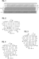
- FIG. 13 shows a trailing edge 12 of a blade airfoil 10 according to an embodiment of the present invention.
- the pin fin pattern 14 may be located along an interior surface of an outer wall.
- the pin fin pattern 14 may be located along the trailing edge wall along the trailing edge 12 and extending from an airfoil cavity 42 to an interior surface of the outer wall.
- the trailing edge 12 is used as an example of a location for the pin fin pattern 14; the location however, is not exclusive to the trialing edge 12 of the blade.
- the pin fin pattern 14 may be located wherever high pressure drop and high heat transfer is required, such as in multiwall applications and the like.
- the details of the cooling circuit 32 are not discussed here, other than the pin fin pattern 14 across an interior surface of an outer wall of the airfoil 10. Aft of a rear boundary of a last channel of the cooling circuit 32 of the blade airfoil 10 is an example of an embodiment of the present invention.
- the cooling circuit 32 ends with a plurality of elements 16 such as shown inFIG. 1.
- the figure shows the plurality of elements 16 of the pin fin pattern 14 that runs the radial length of the blade.
- the pin fin pattern 14 is highly packed with high aspect ratio features.
- FIG. 2 through FIG. 11 show various examples of the pin fin pattern 14 that is created by the plurality of elements 16 that may be used within embodiments of the present invention.
- Each element 16 within the pin fin pattern 14 may be the same as any other element 16 within that pin fin pattern 14.
- Elements 16 of the plurality of elements 16 can be continuous, continuous as an alternating direction pattern as shown in FIG. 7 , or using different elements 16 to complete the pin fin pattern 14.
- the plurality of elements 16 is placed span-wise in columns together aligned in a series of rows.
- the number of rows N is at least four.
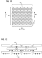
- An example is shown in FIG. 11 with thirteen rows N however, there is the ability to include more rows N in the embodiments.
- the plurality of elements 16 is placed across an interior surface of an outer wall of the airfoil 10.
- the plurality of elements 16 creates the pin fin pattern 14 based on the shape of each of the plurality of elements 16 within the pin fin pattern 14.
- FIG. 2 through FIG. 10 also shows the limitations of the elements 16 within each specific pin fin pattern 14.
- the number of rows N is one limitation of the specific pin fin pattern 14.
- Each element 16 of the plurality of elements 16 are each a specific shape that are, in a pin fin pattern 14, put together in a tightly packed configuration in order to achieve operational efficiency.
- Each element 16 includes an inner length Lc between an inner top edge 38 and an inner bottom edge 40. The inner length Lc being the length of an individual element 16.
- Each element 16 also includes an inner width w between an inner left edge 34 and an inner right edge 36. The inner width w being the width of an individual element 16.
- various lengths are set to make the pattern consistent with a high aspect ratio.
- the plurality of elements 16 includes a pin fin pattern length that extends from the inner top edge 38 of one element to the inner top edge 38 of the next element within a column.
- the pin fin pattern length is designated as Y.
- the plurality of elements 16 includes a pin fin pattern width that extends from the inner left edge 34 of one element to the inner left edge 34 of an element 16 in the next row.
- the pin fin pattern width is designated as X.
- the plurality of elements 16 extends lengthwise in a span-wise direction SW along the airfoil 10 and extends widthwise in an axial direction AD.
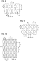
- FIG. 11 is another example of the highly packed plurality of elements where N equals 13 of the rows of plurality of elements across an interior surface of an airfoil 10. Corners 46 of each of the elements 16 have diameters that may include limitations as well. There can be a range from a zero radius corner, to circular arcs with radius equaling w/2 along the corners 46 of each element 16.
- an embodiment may have elements 16 with rectangular shapes 18.
- the corners 46on these rectangular shapes may have zero radius corners providing as sharp of a cut as possible.
- the corners 46 may have arcs.
- the radius of those arcs may have a range that may include having a radius equaling width divided by two, w/2.
- FIGs. 2 through 11 show various embodiments of sections of the pin fin pattern 14.
- the pin fin pattern 14 can be varied in pin shape variation, Lc, L C2 and w, and gap separation, X and Y.
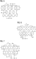
- FIG. 2 shows a plurality of elements 16 that include generally extended rectangular shapes 18. The longer portions of the rectangles are positioned span-wise.
- FIG. 3 displays a plurality of elements 16 that include generally a double chevron shape 20. The double chevron shapes 20 are sideways looking span-wise along the blade airfoil 10.
- FIG. 4 shows a plurality of elements 16 that include generally a modified double chevron shape 22 where a central portion extends past the width of a pair of ends on each element 16 and theend portions are smaller than the evenly spaced double chevron shapes 20 as shown in FIG. 3 .
- the modified double chevron shape 22 is positioned along its side looking span-wise along the blade.
- FIG. 5 shows a plurality of elements 16 that include a generally "crown" shape 44.
- the crown shape includes a flat surface that angles up to the sides and the opposite side includes zig-zag or crown shape.
- FIG. 6 shows a plurality of elements 16 that include a generally diamond shape 24.
- FIG. 7 shows a plurality of elements 16 that include generally triangle shapes 26 in alternating directions pointing towards and away from the main portion of the blade.
- FIG. 8 shows a plurality of elements 16 that include generally rectangular shapes 18. The FIG. 8 embodiment includes a smaller inner length Lc than as shown in FIG. 2 with the same inner width w.
- FIG. 9 shows a plurality of elements that include generally triangle shapes 26 with each triangle facing the same direction and with the base of each triangle shape 26 making contact with the cooling fluid first.
- FIG. 10 shows a plurality of elements 16 that include generally I-beam shapes 28 with the cross portions along the inner top edge and the inner bottom edge of each element 16 and a main portion that runs perpendicularly from the cross portions. For the generally I-beam shapes 28, an additional width L C2 is shown.
- the additional width L C2 is the width of the cross portion of the I-beam shape.
- the inner width w designates the width of the main portion.
- the FIG. 2 through FIG. 10 show the plurality of elements 16 with the flow of the cooling fluid moving from left to right.
- the pin fin pattern width X, pin fin pattern length Y, inner width w, inner length Lc, and the additional width L C2 all can be varied within one pin fin pattern 14 in order to optimize the pressure drop and heat transfer.
- the number of rows N available increases with the ratios listed above adjusted for pressure drop and heat transfer.
- FIG. 12 is an example of the cooling air path as the cooling air moves through the plurality of elements 16 of the pin fin pattern 14.
- there is a dynamic change in direction that allows for a high pressure drop as the cooling air is spread out along the path.
- Hard turns in between each of the elements 16 in the plurality of elements 16 increases the pressure drops as the flow of cooling air 30 moves within the pin fin pattern 14.
- the spacing between the elements 16 of the plurality of elements 16 and the sharpness of corners of each element 16 cannot be achieved with conventional casting methods.
- the turbine element may be manufactured by casting through a manufacturing method including stack lamination with certain molding processes can be used as a casting process that may allow for the detail required for embodiments of the present invention, which is based on the Selective Laser Melting (SLM) manufacturing method.
- SLM Selective Laser Melting
- the technology allows for the detail within the individual elements 16 within the plurality of elements 16.
- the spacing in between each element 16 can be measured in millimeters.
Landscapes
- Engineering & Computer Science (AREA)
- Mechanical Engineering (AREA)
- General Engineering & Computer Science (AREA)
- Turbine Rotor Nozzle Sealing (AREA)
Description
- The present invention relates to gas turbine engines and more specifically to a turbine element for high pressure drop and heat transfer.
- In an axial flow industrial gas turbine engine, hot compressed gas is produced. The hot gas flow is passed through a turbine and expands to produce mechanical work used to drive an output shaft, such as in an electric generator for power production. The turbine generally includes multiple stages of stator vanes and rotor blades to convert the energy from the hot gas flow into mechanical energy that drives the rotor shaft of the engine.
- A combustion system receives air from a compressor and raises it to a high energy level by mixing in fuel and burning the mixture, after which products of the combustor are expanded through the turbine.
- Gas turbines are becoming larger, more efficient, and more robust. Large blades and vanes are being utilized, especially in the hot section of the engine system. In view of high pressure ratios and high engine firing temperatures implemented in modern engines, certain components, such as airfoils, e.g., stationary vanes and rotating blades within the turbine section, must be cooled with cooling fluid, such as air discharged from a compressor in the compressor section, to prevent overheating of the components. When large amounts of cooling occur, however, reduction in efficiency and increases in leakages occur. Turbine elements with cooling technologies are described in
US 4 752 186 A1 ,EP 2 143 883 A andUS 5 660 523 A . - Current cooling technology uses orifice plates at the flow inlet. This leads to low pressure in the cooling passages and problems with backflow margins. Further, it does not increase the heat transfer. These features fail to provide the capability to limit the flow to levels that are needed by advanced engines, while maintaining the required heat transfer within the limitations of advanced manufacturing methods.
- In one aspect of the present invention, a turbine element comprises: a generally elongated airfoil having a leading edge and a trailing edge connected to a pressure side and a suction side defining an outer wall, and a cooling circuit, wherein the cooling circuit comprises: a plurality of elements radially placed in columns together aligned in a series of rows of at least four rows across an interior surface of the outer wall of the airfoil, creating a pin fin pattern based on the shape of each of the plurality of elements, wherein each element comprises: an inner length between an inner top edge and an inner bottom edge, an inner width between an inner left edge and an inner right edge, wherein the pin fin patternincludes pin fin pattern lengths that extend from the inner top edge of one element to the inner top edge of the next element within a column, and pin fin pattern widths that extend from the inner left edge of one element to the inner left edge of an element in the next row, wherein the plurality of elements extend lengthwise in a span-wise direction along the airfoil and extend widthwise in an axial direction, wherein the aspect ratio of inner length over the inner width of each element is equal to or greater than 2:1, wherein the ratio of pin fin pattern lengths over the inner length is equal to or less than 2:1, wherein the ratio of pin fin pattern widths over the inner width is equal to or less than 4:1, wherein the turbine element is manufactured by selective laser melting (SLM).
- These and other features, aspects and advantages of the present invention will become better understood with reference to the following drawings, description and claims.
- The invention is shown in more detail by help of figures. The figures show preferred configurations and do not limit the scope of the invention.
-
FIG 1 is a mean sectional view of a trailing edge of a blade airfoil according to an exemplary embodiment of the present invention; -
FIGS 2-11 are sample portions of pin fin patterns according to various exemplary embodiments of the present invention; -
FIG 12 is a sample portion of a pattern of an exemplary embodiment of the present invention and the flow paths taken around the pattern; and -
FIG 13 is an exemplary example of a cooling circuit within a blade airfoil within the prior art. - In the following detailed description of the preferred embodiment, reference is made to the accompanying drawings that form a part hereof, and in which is shown by way of illustration, and not by way of limitation, a specific embodiment in which the invention may be practiced.
- Broadly, an embodiment of the present invention provides a turbine element for high pressure drop and heat transfer. The turbine element includes a plurality of elements radially placed in columns together aligned in a series of rows of at least four rows across an interior surface of an outer wall of an airfoil, creating a pin fin pattern based on the shape of each of the plurality of elements, wherein each element includes an inner length between an inner top edge and an inner bottom edge, an inner width between an inner left edge and an inner right edge. The pin fin pattern is highly packed and fills a portion of the interior surface of the outer wall of the airfoil.
- A gas turbine engine may comprise a compressor section (not shown), a combustor (not shown) and a turbine section (not shown). The compressor section compresses ambient air. The combustor combines the compressed air with a fuel and ignites the mixture creating combustion products comprising hotgases that form a working fluid. The working fluid travels to the turbine section. Within the turbine section are circumferential rows of vanes and blades, the blades being coupled to a rotor. Each pair of rows of vanes and blades forms a stage in theturbine section. The turbine section comprises a turbine casing, which houses the vanes, blades and rotor. A blade of a gas turbine receives high temperature gases from a combustion system in order to produce mechanical work of a shaft rotation.
- The vane and blade assemblies in the turbine section are exposed to the high temperature working gas as the high temperature working gas passes through the turbine section. Cooling
air 30 from the compressor section may be provided to cool the vane and blade assemblies, as will be described herein. - A reduction in component cooling flow and increase in heat transfer is desirable. Embodiments of the present invention provide a
pin fin pattern 14 with a high aspect ratio for high pressure drop and high heat transfer. Thepin fin pattern 14, as will be discussed in detail below, will provide improved increased heat transfer. - A turbine element such as the blade or the vane includes a generally
elongated airfoil 10. Theairfoil 10 has a leadingedge and atrailing edge 12 that connects to a pressure side and a suction side. Acooling circuit 32 also is included in theairfoil 10 to reduce temperatures to protect the material of theairfoil 10 while in service. Thecooling circuit 32 includes aseries of paths within theairfoil 10 that allow for coolingair 30 to be introduced into the interior of theairfoil 10 to reduce temperatures. A basic example of thecooling circuit 32 is shown inFIG. 13 .FIG. 1 shows atrailing edge 12 of ablade airfoil 10 according to an embodiment of the present invention. Thepin fin pattern 14 may be located along an interior surface of an outer wall. Thepin fin pattern 14 may be located along the trailing edge wall along thetrailing edge 12 and extending from anairfoil cavity 42 to an interior surface of the outer wall. Thetrailing edge 12 is used as an example of a location for thepin fin pattern 14; the location however, is not exclusive to the trialingedge 12 of the blade. Thepin fin pattern 14 may be located wherever high pressure drop and high heat transfer is required, such as in multiwall applications and the like. The details of thecooling circuit 32 are not discussed here, other than thepin fin pattern 14 across an interior surface of an outer wall of theairfoil 10. Aft of a rear boundary of a last channel of thecooling circuit 32 of theblade airfoil 10 is an example of an embodiment of the present invention. Thecooling circuit 32 ends with a plurality ofelements 16 such as shown inFIG. 1. The figure shows the plurality ofelements 16 of thepin fin pattern 14 that runs the radial length of the blade. Thepin fin pattern 14 is highly packed with high aspect ratio features. -
FIG. 2 through FIG. 11 show various examples of thepin fin pattern 14 that is created by the plurality ofelements 16 that may be used within embodiments of the present invention. Eachelement 16 within thepin fin pattern 14 may be the same as anyother element 16 within thatpin fin pattern 14.Elements 16 of the plurality ofelements 16 can be continuous, continuous as an alternating direction pattern as shown inFIG. 7 , or usingdifferent elements 16 to complete thepin fin pattern 14. The plurality ofelements 16 is placed span-wise in columns together aligned in a series of rows. The number of rows N is at least four. An example is shown inFIG. 11 with thirteen rows N however, there is the ability to include more rows N in the embodiments. The plurality ofelements 16 is placed across an interior surface of an outer wall of theairfoil 10. The plurality ofelements 16 creates thepin fin pattern 14 based on the shape of each of the plurality ofelements 16 within thepin fin pattern 14. -
FIG. 2 through FIG. 10 also shows the limitations of theelements 16 within each specificpin fin pattern 14. As mentioned above, the number of rows N is one limitation of the specificpin fin pattern 14. Eachelement 16 of the plurality ofelements 16 are each a specific shape that are, in apin fin pattern 14, put together in a tightly packed configuration in order to achieve operational efficiency. Eachelement 16 includes an inner length Lc between an innertop edge 38 and aninner bottom edge 40. The inner length Lc being the length of anindividual element 16. Eachelement 16 also includes an inner width w between an inner left edge 34 and an innerright edge 36. The inner width w being the width of anindividual element 16. Within thepin fin pattern 14 various lengths are set to make the pattern consistent with a high aspect ratio. The plurality ofelements 16 includes a pin fin pattern length that extends from the innertop edge 38 of one element to the innertop edge 38 of the next element within a column. The pin fin pattern length is designated as Y. The plurality ofelements 16 includes a pin fin pattern width that extends from the inner left edge 34 of one element to the inner left edge 34 of anelement 16 in the next row. The pin fin pattern width is designated as X. The plurality ofelements 16 extends lengthwise in a span-wise direction SW along theairfoil 10 and extends widthwise in an axial direction AD. - Within each specific pattern for each embodiment, limitations of these variables may be made in order to provide high pressure drops and heat transfer. For each
pin fin pattern 14, the aspect ratio of Lc/w is greater than or equal to 2:1. For eachpin fin pattern 14, the ratio of Y/ Lc is equal to or less than 2:1. For eachpin fin pattern 14, the ratio of X/w is equal to or less than 4:1.FIG. 11 is another example of the highly packed plurality of elements where N equals 13 of the rows of plurality of elements across an interior surface of anairfoil 10.Corners 46 of each of theelements 16 have diameters that may include limitations as well. There can be a range from a zero radius corner, to circular arcs with radius equaling w/2 along thecorners 46 of eachelement 16. For example, an embodiment may haveelements 16 withrectangular shapes 18. The corners 46on these rectangular shapes may have zero radius corners providing as sharp of a cut as possible. In other embodiments, thecorners 46 may have arcs. The radius of those arcs may have a range that may include having a radius equaling width divided by two, w/2. - As mentioned above,
FIGs. 2 through 11 show various embodiments of sections of thepin fin pattern 14. Thepin fin pattern 14 can be varied in pin shape variation, Lc, LC2 and w, and gap separation, X and Y.FIG. 2 shows a plurality ofelements 16 that include generally extended rectangular shapes 18. The longer portions of the rectangles are positioned span-wise.FIG. 3 displays a plurality ofelements 16 that include generally adouble chevron shape 20. The double chevron shapes 20 are sideways looking span-wise along theblade airfoil 10.FIG. 4 shows a plurality ofelements 16 that include generally a modifieddouble chevron shape 22 where a central portion extends past the width of a pair of ends on eachelement 16 and theend portions are smaller than the evenly spaced double chevron shapes 20 as shown inFIG. 3 . Again, the modifieddouble chevron shape 22 is positioned along its side looking span-wise along the blade.FIG. 5 shows a plurality ofelements 16 that include a generally "crown"shape 44. The crown shape includes a flat surface that angles up to the sides and the opposite side includes zig-zag or crown shape.FIG. 6 shows a plurality ofelements 16 that include a generallydiamond shape 24.FIG. 7 shows a plurality ofelements 16 that include generally triangle shapes 26 in alternating directions pointing towards and away from the main portion of the blade.FIG. 8 shows a plurality ofelements 16 that include generally rectangular shapes 18. TheFIG. 8 embodiment includes a smaller inner length Lc than as shown inFIG. 2 with the same inner width w.FIG. 9 shows a plurality of elements that include generally triangle shapes 26 with each triangle facing the same direction and with the base of eachtriangle shape 26 making contact with the cooling fluid first.FIG. 10 shows a plurality ofelements 16 that include generally I-beam shapes 28 with the cross portions along the inner top edge and the inner bottom edge of eachelement 16 and a main portion that runs perpendicularly from the cross portions. For the generally I-beam shapes 28, an additional width LC2 is shown. The additional width LC2 is the width of the cross portion of the I-beam shape. The inner width w designates the width of the main portion. TheFIG. 2 through FIG. 10 show the plurality ofelements 16 with the flow of the cooling fluid moving from left to right. The pin fin pattern width X, pin fin pattern length Y, inner width w, inner length Lc, and the additional width LC2 all can be varied within onepin fin pattern 14 in order to optimize the pressure drop and heat transfer. The number of rows N available increases with the ratios listed above adjusted for pressure drop and heat transfer. -
FIG. 12 is an example of the cooling air path as the cooling air moves through the plurality ofelements 16 of thepin fin pattern 14. As is shown, there is a dynamic change in direction that allows for a high pressure drop as the cooling air is spread out along the path. Hard turns in between each of theelements 16 in the plurality ofelements 16 increases the pressure drops as the flow of coolingair 30 moves within thepin fin pattern 14. The smaller the spacing between each of theelements 16 within the plurality ofelements 16 i.e.X and Y, allows for a greater ability to increase the pressure drop as the cooling air flows through the plurality ofelements 16 of thepin fin pattern 14. The spacing between theelements 16 of the plurality ofelements 16 and the sharpness of corners of eachelement 16 cannot be achieved with conventional casting methods. The turbine element may be manufactured by casting through a manufacturing method including stack lamination with certain molding processes can be used as a casting process that may allow for the detail required for embodiments of the present invention, which is based on the Selective Laser Melting (SLM) manufacturing method. The technology allows for the detail within theindividual elements 16 within the plurality ofelements 16. The spacing in between eachelement 16 can be measured in millimeters. - While specific embodiments have been described in detail, those with ordinary skill in the art will appreciate that various modifications and alternative to those details could be developed in light of the overall teachings of the disclosure. Accordingly, the particular arrangements disclosed are meant to be illustrative only and not limiting as to the scope of the invention, which is to be given the full breadth of the appended claims, and any and all equivalents thereof.
Claims (9)
- A turbine element comprising:
a generally elongated airfoil (10) having a leading edge and a trailing edge (12) connected to a pressure side and a suction side defining an outer wall, and a cooling circuit (32), wherein the cooling circuit (32) comprises:a plurality of elements (16)radially placed in columns together aligned in a series of rows (N) of at least four rows (N) across an interior surface of the outer wall of the airfoil (10), creating a pin fin pattern (14) based on the shape of each of the plurality of elements (16), wherein each element comprises:
an inner length (Lc) between an inner top edge (38) and an inner bottom edge (40), an inner width (w) between an inner left edge (34) and an inner right edge (36),wherein the pin fin pattern (14) includes pin fin pattern lengths (Y) that extend from the inner top edge (38) of one element to the inner top edge of the next element within a column, and pin fin pattern widths (X) that extend from the inner left edge of one element (16) to the inner left edge of an element (16) in the next row,wherein the plurality of elements (16) extend lengthwise in a span-wise direction along the airfoil (10) and extend widthwise in an axial direction,wherein the aspect ratio of inner length (Lc) over the inner width (w) of each element (16) is equal to or greater than 2:1,wherein the ratio of pin fin pattern lengths (Y) over the inner length (Lc) is equal to or less than 2:1,wherein the ratio of pin fin pattern widths (X) over the inner width (w) is equal to or less than 4:1,wherein the turbine element is manufactured by selective laser melting (SLM). - The turbine element according to embodiment 1, wherein the plurality of elements (16) comprises generally extended rectangle shapes (18).
- The turbine element according to embodiment 1, wherein the plurality of elements (16) comprises generally double chevron shapes (20).
- The turbine element according to embodiment 1, wherein the plurality of elements (16) comprises generally modified double chevron shapes (22) with a central portion extends past a width of a pair of ends on each element (16).
- The turbine element according to embodiment 1, wherein the plurality of elements (16) comprises generally diamond shapes (24).
- The turbine element according to embodiment 1, wherein the plurality of elements (16) comprises generally triangle shapes (26).
- The turbine element according to embodiment 1, wherein the plurality of elements (16) comprises generally I-beam shapes (28).
- The turbine element according to embodiment 1, wherein the plurality of elements (16) comprises generally crown shapes (44).
- The turbine element according to embodiment 1, wherein the plurality of elements (16) are located along a trailing edge wall along the trailing edge (12) and extending from an airfoil cavity (42) to an interior surface of the outer wall.
Applications Claiming Priority (1)
| Application Number | Priority Date | Filing Date | Title |
|---|---|---|---|
| PCT/US2017/013892 WO2018136042A1 (en) | 2017-01-18 | 2017-01-18 | Turbine element |
Publications (3)
| Publication Number | Publication Date |
|---|---|
| EP3551851A1 EP3551851A1 (en) | 2019-10-16 |
| EP3551851B1 true EP3551851B1 (en) | 2023-07-12 |
| EP3551851C0 EP3551851C0 (en) | 2023-07-12 |
Family
ID=57956397
Family Applications (1)
| Application Number | Title | Priority Date | Filing Date |
|---|---|---|---|
| EP17702719.0A Active EP3551851B1 (en) | 2017-01-18 | 2017-01-18 | Turbine element |
Country Status (5)
| Country | Link |
|---|---|
| US (1) | US20200003060A1 (en) |
| EP (1) | EP3551851B1 (en) |
| JP (1) | JP2020514628A (en) |
| CN (1) | CN110192005A (en) |
| WO (1) | WO2018136042A1 (en) |
Families Citing this family (5)
| Publication number | Priority date | Publication date | Assignee | Title |
|---|---|---|---|---|
| WO2017095438A1 (en) * | 2015-12-04 | 2017-06-08 | Siemens Aktiengesellschaft | Turbine airfoil with biased trailing edge cooling arrangement |
| KR101983469B1 (en) * | 2017-10-20 | 2019-09-10 | 두산중공업 주식회사 | Ring segment of turbine blade and turbine and gas turbine comprising the same |
| US11603765B1 (en) * | 2021-07-16 | 2023-03-14 | Raytheon Technologies Corporation | Airfoil assembly with fiber-reinforced composite rings and toothed exit slot |
| JP7614980B2 (en) * | 2021-08-25 | 2025-01-16 | 三菱重工航空エンジン株式会社 | Combustor panel and gas turbine combustor |
| US11549378B1 (en) | 2022-06-03 | 2023-01-10 | Raytheon Technologies Corporation | Airfoil assembly with composite rings and sealing shelf |
Family Cites Families (9)
| Publication number | Priority date | Publication date | Assignee | Title |
|---|---|---|---|---|
| US4752186A (en) * | 1981-06-26 | 1988-06-21 | United Technologies Corporation | Coolable wall configuration |
| US5660523A (en) * | 1992-02-03 | 1997-08-26 | General Electric Company | Turbine blade squealer tip peripheral end wall with cooling passage arrangement |
| US7699583B2 (en) * | 2006-07-21 | 2010-04-20 | United Technologies Corporation | Serpentine microcircuit vortex turbulatons for blade cooling |
| EP2143883A1 (en) * | 2008-07-10 | 2010-01-13 | Siemens Aktiengesellschaft | Turbine blade and corresponding casting core |
| CN103075202A (en) * | 2013-01-15 | 2013-05-01 | 上海交通大学 | Impingement cooling structure with grid turbulence effect in turbine blade |
| US20150152738A1 (en) * | 2013-12-02 | 2015-06-04 | George Liang | Turbine airfoil cooling passage with diamond turbulator |
| CN204024723U (en) * | 2014-08-17 | 2014-12-17 | 中国航空工业集团公司沈阳发动机设计研究所 | A kind of split type laminate cooling structure of turborotor |
| US10156157B2 (en) * | 2015-02-13 | 2018-12-18 | United Technologies Corporation | S-shaped trip strips in internally cooled components |
| CN105422188A (en) * | 2016-01-13 | 2016-03-23 | 北京航空航天大学 | Turbine blade with heat shield type composite cooling structure |
-
2017
- 2017-01-18 EP EP17702719.0A patent/EP3551851B1/en active Active
- 2017-01-18 JP JP2019559259A patent/JP2020514628A/en active Pending
- 2017-01-18 WO PCT/US2017/013892 patent/WO2018136042A1/en not_active Ceased
- 2017-01-18 CN CN201780083875.4A patent/CN110192005A/en active Pending
- 2017-01-18 US US16/465,207 patent/US20200003060A1/en not_active Abandoned
Also Published As
| Publication number | Publication date |
|---|---|
| WO2018136042A1 (en) | 2018-07-26 |
| US20200003060A1 (en) | 2020-01-02 |
| CN110192005A (en) | 2019-08-30 |
| JP2020514628A (en) | 2020-05-21 |
| EP3551851A1 (en) | 2019-10-16 |
| EP3551851C0 (en) | 2023-07-12 |
Similar Documents
| Publication | Publication Date | Title |
|---|---|---|
| EP3551851B1 (en) | Turbine element | |
| CN1987055B (en) | Counter-cooled turbine nozzle | |
| US9447692B1 (en) | Turbine rotor blade with tip cooling | |
| EP1543219B1 (en) | Turbine blade turbulator cooling design | |
| US8281604B2 (en) | Divergent turbine nozzle | |
| US7544044B1 (en) | Turbine airfoil with pedestal and turbulators cooling | |
| US9004866B2 (en) | Turbine blade incorporating trailing edge cooling design | |
| US6644914B2 (en) | Abradable seals | |
| US9938835B2 (en) | Method and systems for providing cooling for a turbine assembly | |
| EP3006670A2 (en) | Turbine blades and methods of forming turbine blades having lifted rib turbulator structures | |
| US9932837B2 (en) | Low pressure loss cooled blade | |
| US11415000B2 (en) | Turbine airfoil with trailing edge features and casting core | |
| US11519281B2 (en) | Impingement insert for a gas turbine engine | |
| EP3390780B1 (en) | Cooling system for mid-frame torque discs downstream from a compressor assembly in a gas turbine engine | |
| US11193378B2 (en) | Turbine airfoil with trailing edge framing features | |
| US10502068B2 (en) | Engine with chevron pin bank | |
| US11111795B2 (en) | Turbine rotor airfoil and corresponding method for reducing pressure loss in a cavity within a blade | |
| EP3336317B1 (en) | Cooling pocket for the platform of a turbine nozzle | |
| EP3184736B1 (en) | Angled heat transfer pedestal | |
| WO2019040316A1 (en) | Turbine blade with leading edge showerhead hole arrangement | |
| WO2017039568A1 (en) | Turbine airfoil cooling channel with fenced pedestals | |
| EP2378071A1 (en) | Turbine assembly having cooling arrangement and method of cooling | |
| WO2020149854A1 (en) | Pre-swirler with pre-swirler plug for gas turbine engine | |
| WO2017003457A1 (en) | Turbine blade with integrated multiple pass cooling circuits |
Legal Events
| Date | Code | Title | Description |
|---|---|---|---|
| STAA | Information on the status of an ep patent application or granted ep patent |
Free format text: STATUS: UNKNOWN |
|
| STAA | Information on the status of an ep patent application or granted ep patent |
Free format text: STATUS: THE INTERNATIONAL PUBLICATION HAS BEEN MADE |
|
| PUAI | Public reference made under article 153(3) epc to a published international application that has entered the european phase |
Free format text: ORIGINAL CODE: 0009012 |
|
| STAA | Information on the status of an ep patent application or granted ep patent |
Free format text: STATUS: REQUEST FOR EXAMINATION WAS MADE |
|
| 17P | Request for examination filed |
Effective date: 20190710 |
|
| AK | Designated contracting states |
Kind code of ref document: A1 Designated state(s): AL AT BE BG CH CY CZ DE DK EE ES FI FR GB GR HR HU IE IS IT LI LT LU LV MC MK MT NL NO PL PT RO RS SE SI SK SM TR |
|
| AX | Request for extension of the european patent |
Extension state: BA ME |
|
| DAV | Request for validation of the european patent (deleted) | ||
| DAX | Request for extension of the european patent (deleted) | ||
| RAP1 | Party data changed (applicant data changed or rights of an application transferred) |
Owner name: SIEMENS ENERGY GLOBAL GMBH & CO. KG |
|
| STAA | Information on the status of an ep patent application or granted ep patent |
Free format text: STATUS: EXAMINATION IS IN PROGRESS |
|
| 17Q | First examination report despatched |
Effective date: 20210301 |
|
| GRAJ | Information related to disapproval of communication of intention to grant by the applicant or resumption of examination proceedings by the epo deleted |
Free format text: ORIGINAL CODE: EPIDOSDIGR1 |
|
| STAA | Information on the status of an ep patent application or granted ep patent |
Free format text: STATUS: GRANT OF PATENT IS INTENDED |
|
| GRAP | Despatch of communication of intention to grant a patent |
Free format text: ORIGINAL CODE: EPIDOSNIGR1 |
|
| INTG | Intention to grant announced |
Effective date: 20230207 |
|
| GRAS | Grant fee paid |
Free format text: ORIGINAL CODE: EPIDOSNIGR3 |
|
| GRAA | (expected) grant |
Free format text: ORIGINAL CODE: 0009210 |
|
| STAA | Information on the status of an ep patent application or granted ep patent |
Free format text: STATUS: THE PATENT HAS BEEN GRANTED |
|
| AK | Designated contracting states |
Kind code of ref document: B1 Designated state(s): AL AT BE BG CH CY CZ DE DK EE ES FI FR GB GR HR HU IE IS IT LI LT LU LV MC MK MT NL NO PL PT RO RS SE SI SK SM TR |
|
| REG | Reference to a national code |
Ref country code: CH Ref legal event code: EP |
|
| REG | Reference to a national code |
Ref country code: IE Ref legal event code: FG4D |
|
| REG | Reference to a national code |
Ref country code: DE Ref legal event code: R096 Ref document number: 602017071155 Country of ref document: DE |
|
| U01 | Request for unitary effect filed |
Effective date: 20230807 |
|
| U07 | Unitary effect registered |
Designated state(s): AT BE BG DE DK EE FI FR IT LT LU LV MT NL PT SE SI Effective date: 20230817 |
|
| REG | Reference to a national code |
Ref country code: LT Ref legal event code: MG9D |
|
| PG25 | Lapsed in a contracting state [announced via postgrant information from national office to epo] |
Ref country code: GR Free format text: LAPSE BECAUSE OF FAILURE TO SUBMIT A TRANSLATION OF THE DESCRIPTION OR TO PAY THE FEE WITHIN THE PRESCRIBED TIME-LIMIT Effective date: 20231013 |
|
| PG25 | Lapsed in a contracting state [announced via postgrant information from national office to epo] |
Ref country code: ES Free format text: LAPSE BECAUSE OF FAILURE TO SUBMIT A TRANSLATION OF THE DESCRIPTION OR TO PAY THE FEE WITHIN THE PRESCRIBED TIME-LIMIT Effective date: 20230712 |
|
| PG25 | Lapsed in a contracting state [announced via postgrant information from national office to epo] |
Ref country code: IS Free format text: LAPSE BECAUSE OF FAILURE TO SUBMIT A TRANSLATION OF THE DESCRIPTION OR TO PAY THE FEE WITHIN THE PRESCRIBED TIME-LIMIT Effective date: 20231112 |
|
| PG25 | Lapsed in a contracting state [announced via postgrant information from national office to epo] |
Ref country code: RS Free format text: LAPSE BECAUSE OF FAILURE TO SUBMIT A TRANSLATION OF THE DESCRIPTION OR TO PAY THE FEE WITHIN THE PRESCRIBED TIME-LIMIT Effective date: 20230712 Ref country code: NO Free format text: LAPSE BECAUSE OF FAILURE TO SUBMIT A TRANSLATION OF THE DESCRIPTION OR TO PAY THE FEE WITHIN THE PRESCRIBED TIME-LIMIT Effective date: 20231012 Ref country code: IS Free format text: LAPSE BECAUSE OF FAILURE TO SUBMIT A TRANSLATION OF THE DESCRIPTION OR TO PAY THE FEE WITHIN THE PRESCRIBED TIME-LIMIT Effective date: 20231112 Ref country code: HR Free format text: LAPSE BECAUSE OF FAILURE TO SUBMIT A TRANSLATION OF THE DESCRIPTION OR TO PAY THE FEE WITHIN THE PRESCRIBED TIME-LIMIT Effective date: 20230712 Ref country code: GR Free format text: LAPSE BECAUSE OF FAILURE TO SUBMIT A TRANSLATION OF THE DESCRIPTION OR TO PAY THE FEE WITHIN THE PRESCRIBED TIME-LIMIT Effective date: 20231013 Ref country code: ES Free format text: LAPSE BECAUSE OF FAILURE TO SUBMIT A TRANSLATION OF THE DESCRIPTION OR TO PAY THE FEE WITHIN THE PRESCRIBED TIME-LIMIT Effective date: 20230712 |
|
| U20 | Renewal fee for the european patent with unitary effect paid |
Year of fee payment: 8 Effective date: 20240125 |
|
| PG25 | Lapsed in a contracting state [announced via postgrant information from national office to epo] |
Ref country code: PL Free format text: LAPSE BECAUSE OF FAILURE TO SUBMIT A TRANSLATION OF THE DESCRIPTION OR TO PAY THE FEE WITHIN THE PRESCRIBED TIME-LIMIT Effective date: 20230712 |
|
| REG | Reference to a national code |
Ref country code: DE Ref legal event code: R097 Ref document number: 602017071155 Country of ref document: DE |
|
| PG25 | Lapsed in a contracting state [announced via postgrant information from national office to epo] |
Ref country code: SM Free format text: LAPSE BECAUSE OF FAILURE TO SUBMIT A TRANSLATION OF THE DESCRIPTION OR TO PAY THE FEE WITHIN THE PRESCRIBED TIME-LIMIT Effective date: 20230712 Ref country code: RO Free format text: LAPSE BECAUSE OF FAILURE TO SUBMIT A TRANSLATION OF THE DESCRIPTION OR TO PAY THE FEE WITHIN THE PRESCRIBED TIME-LIMIT Effective date: 20230712 Ref country code: CZ Free format text: LAPSE BECAUSE OF FAILURE TO SUBMIT A TRANSLATION OF THE DESCRIPTION OR TO PAY THE FEE WITHIN THE PRESCRIBED TIME-LIMIT Effective date: 20230712 Ref country code: SK Free format text: LAPSE BECAUSE OF FAILURE TO SUBMIT A TRANSLATION OF THE DESCRIPTION OR TO PAY THE FEE WITHIN THE PRESCRIBED TIME-LIMIT Effective date: 20230712 |
|
| PLBE | No opposition filed within time limit |
Free format text: ORIGINAL CODE: 0009261 |
|
| STAA | Information on the status of an ep patent application or granted ep patent |
Free format text: STATUS: NO OPPOSITION FILED WITHIN TIME LIMIT |
|
| 26N | No opposition filed |
Effective date: 20240415 |
|
| PG25 | Lapsed in a contracting state [announced via postgrant information from national office to epo] |
Ref country code: MC Free format text: LAPSE BECAUSE OF FAILURE TO SUBMIT A TRANSLATION OF THE DESCRIPTION OR TO PAY THE FEE WITHIN THE PRESCRIBED TIME-LIMIT Effective date: 20230712 |
|
| PG25 | Lapsed in a contracting state [announced via postgrant information from national office to epo] |
Ref country code: MC Free format text: LAPSE BECAUSE OF FAILURE TO SUBMIT A TRANSLATION OF THE DESCRIPTION OR TO PAY THE FEE WITHIN THE PRESCRIBED TIME-LIMIT Effective date: 20230712 |
|
| PG25 | Lapsed in a contracting state [announced via postgrant information from national office to epo] |
Ref country code: IE Free format text: LAPSE BECAUSE OF NON-PAYMENT OF DUE FEES Effective date: 20240118 |
|
| PG25 | Lapsed in a contracting state [announced via postgrant information from national office to epo] |
Ref country code: IE Free format text: LAPSE BECAUSE OF NON-PAYMENT OF DUE FEES Effective date: 20240118 |
|
| U20 | Renewal fee for the european patent with unitary effect paid |
Year of fee payment: 9 Effective date: 20250127 |
|
| PGFP | Annual fee paid to national office [announced via postgrant information from national office to epo] |
Ref country code: CH Payment date: 20250201 Year of fee payment: 9 |
|
| PGFP | Annual fee paid to national office [announced via postgrant information from national office to epo] |
Ref country code: GB Payment date: 20250121 Year of fee payment: 9 |
|
| PG25 | Lapsed in a contracting state [announced via postgrant information from national office to epo] |
Ref country code: CY Free format text: LAPSE BECAUSE OF FAILURE TO SUBMIT A TRANSLATION OF THE DESCRIPTION OR TO PAY THE FEE WITHIN THE PRESCRIBED TIME-LIMIT; INVALID AB INITIO Effective date: 20170118 |
|
| PG25 | Lapsed in a contracting state [announced via postgrant information from national office to epo] |
Ref country code: HU Free format text: LAPSE BECAUSE OF FAILURE TO SUBMIT A TRANSLATION OF THE DESCRIPTION OR TO PAY THE FEE WITHIN THE PRESCRIBED TIME-LIMIT; INVALID AB INITIO Effective date: 20170118 |
|
| PG25 | Lapsed in a contracting state [announced via postgrant information from national office to epo] |
Ref country code: TR Free format text: LAPSE BECAUSE OF FAILURE TO SUBMIT A TRANSLATION OF THE DESCRIPTION OR TO PAY THE FEE WITHIN THE PRESCRIBED TIME-LIMIT Effective date: 20230712 |
|
| REG | Reference to a national code |
Ref country code: CH Ref legal event code: U11 Free format text: ST27 STATUS EVENT CODE: U-0-0-U10-U11 (AS PROVIDED BY THE NATIONAL OFFICE) Effective date: 20260201 |
|
| U20 | Renewal fee for the european patent with unitary effect paid |
Year of fee payment: 10 Effective date: 20260126 |