EP3551806B1 - Unmanned or remotely operated platform - Google Patents
Unmanned or remotely operated platform Download PDFInfo
- Publication number
- EP3551806B1 EP3551806B1 EP17811955.8A EP17811955A EP3551806B1 EP 3551806 B1 EP3551806 B1 EP 3551806B1 EP 17811955 A EP17811955 A EP 17811955A EP 3551806 B1 EP3551806 B1 EP 3551806B1
- Authority
- EP
- European Patent Office
- Prior art keywords
- topside
- standardized
- sections
- unmanned
- construction
- Prior art date
- Legal status (The legal status is an assumption and is not a legal conclusion. Google has not performed a legal analysis and makes no representation as to the accuracy of the status listed.)
- Active
Links
Images


Classifications
-
- E—FIXED CONSTRUCTIONS
- E02—HYDRAULIC ENGINEERING; FOUNDATIONS; SOIL SHIFTING
- E02B—HYDRAULIC ENGINEERING
- E02B17/00—Artificial islands mounted on piles or like supports, e.g. platforms on raisable legs or offshore constructions; Construction methods therefor
- E02B17/0034—Maintenance, repair or inspection of offshore constructions
-
- B—PERFORMING OPERATIONS; TRANSPORTING
- B63—SHIPS OR OTHER WATERBORNE VESSELS; RELATED EQUIPMENT
- B63B—SHIPS OR OTHER WATERBORNE VESSELS; EQUIPMENT FOR SHIPPING
- B63B35/00—Vessels or similar floating structures specially adapted for specific purposes and not otherwise provided for
- B63B35/44—Floating buildings, stores, drilling platforms, or workshops, e.g. carrying water-oil separating devices
- B63B35/4413—Floating drilling platforms, e.g. carrying water-oil separating devices
-
- E—FIXED CONSTRUCTIONS
- E21—EARTH OR ROCK DRILLING; MINING
- E21B—EARTH OR ROCK DRILLING; OBTAINING OIL, GAS, WATER, SOLUBLE OR MELTABLE MATERIALS OR A SLURRY OF MINERALS FROM WELLS
- E21B33/00—Sealing or packing boreholes or wells
- E21B33/02—Surface sealing or packing
- E21B33/03—Well heads; Setting-up thereof
- E21B33/035—Well heads; Setting-up thereof specially adapted for underwater installations
-
- B—PERFORMING OPERATIONS; TRANSPORTING
- B63—SHIPS OR OTHER WATERBORNE VESSELS; RELATED EQUIPMENT
- B63B—SHIPS OR OTHER WATERBORNE VESSELS; EQUIPMENT FOR SHIPPING
- B63B35/00—Vessels or similar floating structures specially adapted for specific purposes and not otherwise provided for
- B63B35/44—Floating buildings, stores, drilling platforms, or workshops, e.g. carrying water-oil separating devices
-
- E—FIXED CONSTRUCTIONS
- E02—HYDRAULIC ENGINEERING; FOUNDATIONS; SOIL SHIFTING
- E02B—HYDRAULIC ENGINEERING
- E02B17/00—Artificial islands mounted on piles or like supports, e.g. platforms on raisable legs or offshore constructions; Construction methods therefor
-
- E—FIXED CONSTRUCTIONS
- E02—HYDRAULIC ENGINEERING; FOUNDATIONS; SOIL SHIFTING
- E02B—HYDRAULIC ENGINEERING
- E02B17/00—Artificial islands mounted on piles or like supports, e.g. platforms on raisable legs or offshore constructions; Construction methods therefor
- E02B17/02—Artificial islands mounted on piles or like supports, e.g. platforms on raisable legs or offshore constructions; Construction methods therefor placed by lowering the supporting construction to the bottom, e.g. with subsequent fixing thereto
- E02B17/027—Artificial islands mounted on piles or like supports, e.g. platforms on raisable legs or offshore constructions; Construction methods therefor placed by lowering the supporting construction to the bottom, e.g. with subsequent fixing thereto steel structures
-
- E—FIXED CONSTRUCTIONS
- E21—EARTH OR ROCK DRILLING; MINING
- E21B—EARTH OR ROCK DRILLING; OBTAINING OIL, GAS, WATER, SOLUBLE OR MELTABLE MATERIALS OR A SLURRY OF MINERALS FROM WELLS
- E21B15/00—Supports for the drilling machine, e.g. derricks or masts
-
- E—FIXED CONSTRUCTIONS
- E21—EARTH OR ROCK DRILLING; MINING
- E21B—EARTH OR ROCK DRILLING; OBTAINING OIL, GAS, WATER, SOLUBLE OR MELTABLE MATERIALS OR A SLURRY OF MINERALS FROM WELLS
- E21B15/00—Supports for the drilling machine, e.g. derricks or masts
- E21B15/02—Supports for the drilling machine, e.g. derricks or masts specially adapted for underwater drilling
-
- E—FIXED CONSTRUCTIONS
- E21—EARTH OR ROCK DRILLING; MINING
- E21B—EARTH OR ROCK DRILLING; OBTAINING OIL, GAS, WATER, SOLUBLE OR MELTABLE MATERIALS OR A SLURRY OF MINERALS FROM WELLS
- E21B7/00—Special methods or apparatus for drilling
- E21B7/12—Underwater drilling
- E21B7/128—Underwater drilling from floating support with independent underwater anchored guide base
-
- E—FIXED CONSTRUCTIONS
- E02—HYDRAULIC ENGINEERING; FOUNDATIONS; SOIL SHIFTING
- E02B—HYDRAULIC ENGINEERING
- E02B17/00—Artificial islands mounted on piles or like supports, e.g. platforms on raisable legs or offshore constructions; Construction methods therefor
- E02B2017/0056—Platforms with supporting legs
- E02B2017/0073—Details of sea bottom engaging footing
- E02B2017/0078—Suction piles, suction cans
Definitions
- the present invention relates to an unmanned or remotely operated platform concept.
- platforms include a jacket standing on the seabed.
- the jacket extends through the body of water and projects above the sea level.
- a topside is mounted on top of the jacket.
- the purpose of this platform concept is to bring the subsea infrastructure to the surface, which makes the wellheads, blow out preventer, Xmas trees, valves, actuators etc. dry and far more accessible.
- un-manned or remotely operated platform must be interpreted broadly.
- the term could be an unmanned wellhead platform, an unmanned platform, remotely operated platform, normally unmanned platform, unmanned process platform or simpler facilities offshore.
- Typical for these platform concepts is that the platform has no permanent manning and the concept grant options for removing typical functions as living quarters, helicopter deck and lifeboats. All these facilities may be found on a service operations vessel (SOV) that may be chosen to serve and operate the unmanned wellhead platform during eg. maintenance campaigns.
- SOV service operations vessel
- the overall design philosophy is to minimize the equipment on the platform, thus minimizing the requirement for visiting the platform for operation and maintenance. Visits to the platform is planned limited to once a year except for unplanned well maintenance. Further, focus is on efficient and safe evacuation if for some reason a leakage and/or fire should occur during a visit.
- Publication WO2016/122334 discloses an unmanned platform supported on a structure arranged on the seabed.
- the platform structure of the publication is standardized so that the same platform may be used on several installation structures.
- Publication US2016/0221648 discloses a floating facility for offshore hydrocarbon production with drilling slots and production slots and a cart that is movable together with a drilling riser above the well bay to drill the well through the drilling riser.
- GB2515021 discloses a support structure for use in an offshore platform.
- the support structure comprises a main support strut having one end anchored to the seabed and guide rail extending to the top of the support strut for cooperation with a framework with a payload slidably mountable to the guide rail for elevating the frame work and payload to the top of the structure.
- an unmanned wellhead platform comprising a jacket design and adapted to be supported on the seabed and projecting above the sea level, which jacket includes a topside installed on top of said jacket.
- the unmanned wellhead platform is distinguished in that the topside is designed as a standardized base concept tailored for repetitive future topside constructions, each topside construction being adapted to the number of wells to be developed, the topside construction being made up by a number of different but standardized sections, each standardized section being dedicated for a particular and predetermined purpose and location in said topside construction.
- some of the standardized sections of the topside construction has defined well slots, each well slot having received its respective and unique number from one and up, each numbered well slot repeatedly receives the same location in the topside construction each time a base topside construction is constructed, hence "standardizing" such base topside construction.
- the many standardized sections adopt different sizes and configurations, though normally grouped in sets of sections having equal dimension. Even if the topside frame construction is subdivided into a number of different sections, each section has its standard in respect of size and intended use.
- the at least one of the standardized sections may be adapted to receive and mount various components associated with a dedicated well.
- the number of standardized sections are grouped in standardized structural sections and standardized equipment sections.
- Each standardized section may span over at least two decks, or alternatively each standardized section may span over three decks, i.e. a cellar deck, a middle deck and a weather deck.
- topside sectioned frame structure may include eight, twelve or sixteen dedicated well slots, each well slot being adapted to receive required components for one respective well. Any number of dedicated well slots are conceivable, but eight, twelve or sixteen are shown here.
- the topside may be rotated in the horizontal plane approximately 45 degrees relative to corner legs of the jacket. This provides benefits with regard to accessibility and reach for a jack-up rig (not shown) to be located adjacent to the unmanned wellhead platform.
- the legs of the jack-up rig are able to straddle over the corner leg of the jacket and in this way being able to arrive as close as possible to the unmanned wellhead platform topside construction and thus the well area.
- the topside construction is adapted and designed for possible future expansion, where such expansion takes place by adding one or more structural section elements as required.
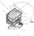
- FIG 1 showing an unmanned wellhead platform 1.
- the platform or more precisely a topside 3, is installed on top of a jacket 10 ( figure 2 ).
- the jacket 10 is designed with legs 9 ( figure 2 ) and adapted to be supported on the seabed.
- the jacket 10 is secured to the seabed by suction buckets (anchors) or piles.
- the jacket 10 is normally a truss structure projecting above the sea level to support the topside frame construction3 on top of the jacket structure.
- a number of risers 2 extend from the seabed up to the topside 3.
- the topside frame construction 3 further includes a swing crane 5 having reach all over the top deck floor 6.
- the topside frame construction 3 is designed as a frame construction (also numbered 3), normally made up by several decks, here three decks are shown.
- the lowest deck is a cellar deck D 1 , next is a XMT deck D 2 and weather deck D 3 on top.
- the top area can easily be expanded or diminished.
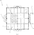
- the topside frame construction 3 is designed as a standardized base concept. This means that the concept is prepared for repetitive future use. However, the topside frame construction 3 needs to be adapted to each project depending on the number of wells to be operated and the site where it is to be located. The topside frame construction 3 could be adjusted according to the number of wells that are needed. This could be any number from 1-16. Further the number of decks are adjusted. The deck area and the height between the decks are defined accordingly.
- the topside frame construction 3 is divided into a number of sections 4. Each section 4 is standardized in respect of size and intended use. However, even if many sections 4 are equal, many sections 4 are different also. Hence, they are grouped into particular sizes, but each size is standardized. Each section size is dedicated for a particular and predetermined purpose and location in the topside frame construction 3. Example of purpose and location are shown in fig. 5-7 , and in the description below referring to the figures.
- Figure 2-4 shows three different embodiments of D3, namely D3', D3", D3'" of the weather deck of the topside frame construction3.
- topside frame construction 3 As more clearly shown in fig. 2 , some of the standardized sections 4 of the topside construction 3 has defined well slots 1 S to 8 S . Each well slot has received its unique number. For future eight well slots topside frame constructions 3 to be built, each numbered well slot 1 S -8 S repeatedly receives exact the same location in the topside frame construction 3. Thus, such base topside frame constructions 3 are named as "standardized".
- the number of standardized sections 4 can be grouped in sets of equal sections, though the sections may adopt different sizes and configurations in the various sets.
- Two coarsely divided groups of sections can be "standardized structural sections” and “standardized equipment sections", as an example. In fig. 2 they are numbered 4' and 4" respectively.
- At least one of the standardized sections 4 is adapted to receive and mount various components associated with a dedicated well.
- the topside construction 3 is rotated in the horizontal plane approximately 45 degrees relative to corner legs 9 of the jacket structure 10.
- This provides benefits with regard to accessibility and reach for a jack-up rig (not shown) to be located adjacent to the unmanned wellhead platform 1.
- the legs of the jack-up rig are able to straddle over the corner leg 9 of the jacket 10 and in this way, being able to arrive as close as possible to the unmanned wellhead platform topside construction 3 and thus the well area.
- a material handling platform 11 is also shown. This platform 11 is located at a desired height above sea level.
- the platform 11 could be, either of the fixed design located at a higher level, or a temporary platform intended for location at a lower level closer to the sea.
- the topside construction 3 is sectioned where the most important parameter for the total size of the topside construction 3 is the number of well slots 1s to 16s.
- the well slots are dedicated to be either producers, injectors, flexibles (both producer and injector) and redundant.
- the unmanned wellhead platform typically has from two to sixteen well slots.
- the well slots numbered 1 S to 16 S are given a fixed location according to numerical value.
- a ten slot unmanned wellhead platform will receive slot locations as shown in fig. 3 up to slot number 10.
- Each well slot has a set of components topside in order to be able to produce or inject the well. This is typically wellhead, XMT (Christmas tree), flow control valves, flow meters and isolation valves.
- XMT Christmas tree
- Each well slot is typically 2,5 X 2,5 meters.
- the wellhead and XMT are installed within this area.
- the topside construction 3 is sectioned with predetermined location and design of the respective sections 4.
- the sections 4 can have different sizes, dependent of the number of well slots and location in the topside construction 3.
- the topside construction 3 can be based on a 20m X 20m deck floor 6 ( fig 1 ) and in three heights (decks). This one has 2-8 wells. However, the number of wells can be expanded, for example as shown in fig. 3 with up to four more wells. Then you need to expand the area with a row of sections 20m X 5,5m as shown in the bottom of fig. 3 . If you expand with four more wells, as shown in fig. 4 , you need to expand the area with another row of sections 20m X 5,5 m as shown on top of fig. 4 .
- Typical values for sections having four different sizes, dependent of the number of well slots, can be: 2-4 wells 14 X 14 X 11m (not shown) 4-8 wells 20 X 20 X 11m ( fig. 2 ) 9-12 wells 20 X 25 (including cantilever in south) ( fig. 3 ) 13-16 wells 20 X 30 (including cantilever in north) ( fig. 4 )
- the equipment has standardized layout (for example the fig. 6 injection system), is sectioned and located in fixed locations for the respective topside sizes and scaled in accordance with the number of wells. Typical sections/areas are:
- a water and gas/injection well on a 10 slots unmanned wellhead platform then will have:
- the construction typically has three deck levels, cellar deck D 1 , xmas tree deck D 2 and weather deck D 3 .
- the well heads are installed together with equipment for flow regulation, flow measurements, isolation valves, manifolds, gas lift etc in the different sections or area as shown in the figures.
- Figure 5-7 discloses three different embodiments D1', D1", D1'" of the cellar deck of the topside frame structure 3. The embodiments corresponding to the weather deck D3', D3", D3'" as disclosed above in figure 2-4 .
- xmas tree deck D 2 On xmas tree deck D 2 , the xmas tree is placed together with equipment for power supply (electro), control systems, inlet of umbilical from the mother platform, injection systems.
- the weather deck D 3 has hatches 12 for access to the various wells.
- the weather deck D3 shields the well area and operates as base for connection to the wells for conducting well intervention.
- the pig skidder can easily be connected to a temporary piping spool connected to the risers 2 down at the cellar deck D 1 .
- the pig skidder is arranged to launch or receive a plug device that is forced through the pipeline system for cleaning purpose after the installation and before the start production/operation of the platform.
- the hook-up philosophy is as follows. It is kept at a minimum, only risers and J-tubes are required.
- the topside is designed for single lift offshore. This means that all components are ready installed and tested. Only hook-up spools are required to complete the connection between topside and jacket. Hook-up spools are fabricated onshore and shipped to the topside. Possible adaptions are made offshore.
- the control system is preferably in an EICT container.
- the choice was to collect electrical and instrument cabinets within the EICT container.
- the size of the container can vary, it is determined by the equipment it is to contain. Primary location for such container will be in direction south on the Xmas tree deck D2, since this will provide a good air direction on Norwegian offshore sector, i.e. prevailing wind is often toward north-east. All equipment within the container are Ex secured.
- the external material handling takes place either to/from Jack-Up Rig (JUR) or to/from Service Operation Vessel (SOV).
- JUR Jack-Up Rig
- SOV Service Operation Vessel
- unmanned wellhead platform also called SOS (subsea on a stick
Landscapes
- Engineering & Computer Science (AREA)
- Life Sciences & Earth Sciences (AREA)
- Mining & Mineral Resources (AREA)
- Geology (AREA)
- General Engineering & Computer Science (AREA)
- Mechanical Engineering (AREA)
- Civil Engineering (AREA)
- Structural Engineering (AREA)
- General Life Sciences & Earth Sciences (AREA)
- Physics & Mathematics (AREA)
- Environmental & Geological Engineering (AREA)
- Fluid Mechanics (AREA)
- Geochemistry & Mineralogy (AREA)
- Ocean & Marine Engineering (AREA)
- Combustion & Propulsion (AREA)
- Chemical & Material Sciences (AREA)
- Architecture (AREA)
- Excavating Of Shafts Or Tunnels (AREA)
- Earth Drilling (AREA)
- Control Of Position, Course, Altitude, Or Attitude Of Moving Bodies (AREA)
Description
- The present invention relates to an unmanned or remotely operated platform concept. Such platforms include a jacket standing on the seabed. The jacket extends through the body of water and projects above the sea level. A topside is mounted on top of the jacket. The purpose of this platform concept is to bring the subsea infrastructure to the surface, which makes the wellheads, blow out preventer, Xmas trees, valves, actuators etc. dry and far more accessible.
- The term un-manned or remotely operated platform must be interpreted broadly. The term could be an unmanned wellhead platform, an unmanned platform, remotely operated platform, normally unmanned platform, unmanned process platform or simpler facilities offshore.
- Typical for these platform concepts is that the platform has no permanent manning and the concept grant options for removing typical functions as living quarters, helicopter deck and lifeboats. All these facilities may be found on a service operations vessel (SOV) that may be chosen to serve and operate the unmanned wellhead platform during eg. maintenance campaigns.
- There is a continuous and ongoing demand and challenge to save cost during the development of oilfields in order to extract hydrocarbons from subsea oil reservoirs in a cost-effective way. It is only in the more recent years it has been proposed to make use of the rather new concept of unmanned wellhead platforms. The alternative would have been to install the wellheads on the seabed. However, the costs of subsea wells have grown extremely the last decades. The total cost for unmanned wellhead platforms is found very beneficial in respect of the expensive subsea concept.
- The overall design philosophy is to minimize the equipment on the platform, thus minimizing the requirement for visiting the platform for operation and maintenance. Visits to the platform is planned limited to once a year except for unplanned well maintenance. Further, focus is on efficient and safe evacuation if for some reason a leakage and/or fire should occur during a visit.
- Publication
WO2016/122334 discloses an unmanned platform supported on a structure arranged on the seabed. The platform structure of the publication is standardized so that the same platform may be used on several installation structures. - Publication
US2016/0221648 discloses a floating facility for offshore hydrocarbon production with drilling slots and production slots and a cart that is movable together with a drilling riser above the well bay to drill the well through the drilling riser. -
GB2515021 - None of the above publications do however discloses a platform structure for an unmanned platform that is adapted and designed for possible future expansion.
- According the present invention, an unmanned wellhead platform comprising a jacket design and adapted to be supported on the seabed and projecting above the sea level, which jacket includes a topside installed on top of said jacket, is provided. The unmanned wellhead platform is distinguished in that the topside is designed as a standardized base concept tailored for repetitive future topside constructions, each topside construction being adapted to the number of wells to be developed, the topside construction being made up by a number of different but standardized sections, each standardized section being dedicated for a particular and predetermined purpose and location in said topside construction.
- In one embodiment, some of the standardized sections of the topside construction has defined well slots, each well slot having received its respective and unique number from one and up, each numbered well slot repeatedly receives the same location in the topside construction each time a base topside construction is constructed, hence "standardizing" such base topside construction.
- The many standardized sections adopt different sizes and configurations, though normally grouped in sets of sections having equal dimension. Even if the topside frame construction is subdivided into a number of different sections, each section has its standard in respect of size and intended use.
- In one embodiment, the at least one of the standardized sections may be adapted to receive and mount various components associated with a dedicated well.
- In one embodiment, the number of standardized sections are grouped in standardized structural sections and standardized equipment sections.
- Each standardized section may span over at least two decks, or alternatively each standardized section may span over three decks, i.e. a cellar deck, a middle deck and a weather deck.
- Further, the topside sectioned frame structure may include eight, twelve or sixteen dedicated well slots, each well slot being adapted to receive required components for one respective well. Any number of dedicated well slots are conceivable, but eight, twelve or sixteen are shown here.
- In one embodiment, the topside may be rotated in the horizontal plane approximately 45 degrees relative to corner legs of the jacket. This provides benefits with regard to accessibility and reach for a jack-up rig (not shown) to be located adjacent to the unmanned wellhead platform. The legs of the jack-up rig are able to straddle over the corner leg of the jacket and in this way being able to arrive as close as possible to the unmanned wellhead platform topside construction and thus the well area.
- In one embodiment, the topside construction is adapted and designed for possible future expansion, where such expansion takes place by adding one or more structural section elements as required.
- While the various aspects of the present invention have been described in general terms above, a more detailed and non-limiting example of embodiments will be described in the following with reference to the drawings, in which:
-
Fig. 1 shows a schematic perspective view an unmanned wellhead platform according to the present invention, -
Fig. 2 shows a schematic top view of a first embodiment of the unmanned wellhead platform shown infigure 1 , the platform having 8 well slots, -
Fig. 3 shows a schematic top view a second embodiment of the unmanned wellhead platform shown infigure 1 , the platform having 12 well slots, -
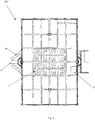
Fig. 4 shows a schematic top view a third embodiment of the unmanned wellhead platform shown infigure 1 , the platform having 16 well slots, -
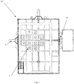
Fig. 5 shows a schematic view from above the first embodiment shown infigure 2 , and with the top deck (weather deck and xmas deck) removed, -
Fig. 6 shows a schematic view from above the second embodiment shown infigure 3 , and with the top deck (weather deck and xmas deck) removed, -
Fig. 7 shows a schematic view from above the third embodiment shown infigure 4 , and with the top deck (weather deck and xmas deck) removed, -
Fig. 8a shows a principal view an exemplary layout of various pipes and components onboard said platform, view from the side -
Figure 8b shows a principal view of an exemplary layout of various pipes and components onboard said platform, viewed from above, -
Fig. 9 shows in schematic view a typical field layout. - Reference is made to
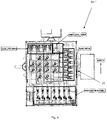
figure 1 showing anunmanned wellhead platform 1. The platform, or more precisely atopside 3, is installed on top of a jacket 10 (figure 2 ). Thejacket 10 is designed with legs 9 (figure 2 ) and adapted to be supported on the seabed. Thejacket 10 is secured to the seabed by suction buckets (anchors) or piles. Thejacket 10 is normally a truss structure projecting above the sea level to support the topside frame construction3 on top of the jacket structure. A number ofrisers 2 extend from the seabed up to thetopside 3. Thetopside frame construction 3 further includes aswing crane 5 having reach all over thetop deck floor 6. - Basically, the
topside frame construction 3 is designed as a frame construction (also numbered 3), normally made up by several decks, here three decks are shown. The lowest deck is a cellar deck D1, next is a XMT deck D2 and weather deck D3 on top. The top area can easily be expanded or diminished. - The
topside frame construction 3 is designed as a standardized base concept. This means that the concept is prepared for repetitive future use. However, thetopside frame construction 3 needs to be adapted to each project depending on the number of wells to be operated and the site where it is to be located. Thetopside frame construction 3 could be adjusted according to the number of wells that are needed. This could be any number from 1-16. Further the number of decks are adjusted. The deck area and the height between the decks are defined accordingly. - The
topside frame construction 3 is divided into a number ofsections 4. Eachsection 4 is standardized in respect of size and intended use. However, even ifmany sections 4 are equal,many sections 4 are different also. Hence, they are grouped into particular sizes, but each size is standardized. Each section size is dedicated for a particular and predetermined purpose and location in thetopside frame construction 3. Example of purpose and location are shown infig. 5-7 , and in the description below referring to the figures. -
Figure 2-4 shows three different embodiments of D3, namely D3', D3", D3'" of the weather deck of the topside frame construction3. - As more clearly shown in
fig. 2 , some of thestandardized sections 4 of thetopside construction 3 has definedwell slots 1S to 8S. Each well slot has received its unique number. For future eight well slots topsideframe constructions 3 to be built, each numbered well slot 1S-8S repeatedly receives exact the same location in thetopside frame construction 3. Thus, such basetopside frame constructions 3 are named as "standardized". - The number of
standardized sections 4 can be grouped in sets of equal sections, though the sections may adopt different sizes and configurations in the various sets. Two coarsely divided groups of sections can be "standardized structural sections" and "standardized equipment sections", as an example. Infig. 2 they are numbered 4' and 4" respectively. - At least one of the
standardized sections 4 is adapted to receive and mount various components associated with a dedicated well. - In the embodiment shown in
fig. 2 , thetopside construction 3 is rotated in the horizontal plane approximately 45 degrees relative to cornerlegs 9 of thejacket structure 10. This provides benefits with regard to accessibility and reach for a jack-up rig (not shown) to be located adjacent to theunmanned wellhead platform 1. The legs of the jack-up rig are able to straddle over thecorner leg 9 of thejacket 10 and in this way, being able to arrive as close as possible to the unmanned wellhead platformtopside construction 3 and thus the well area. Amaterial handling platform 11 is also shown. Thisplatform 11 is located at a desired height above sea level. Theplatform 11 could be, either of the fixed design located at a higher level, or a temporary platform intended for location at a lower level closer to the sea. - As mentioned, the
topside construction 3 is sectioned where the most important parameter for the total size of thetopside construction 3 is the number of well slots 1s to 16s. The well slots are dedicated to be either producers, injectors, flexibles (both producer and injector) and redundant. - Referring to
fig. 2 ,3 and4 , the unmanned wellhead platform typically has from two to sixteen well slots. As mentioned, the well slots numbered 1S to 16S are given a fixed location according to numerical value. For example, a ten slot unmanned wellhead platform will receive slot locations as shown infig. 3 up toslot number 10. - Each well slot has a set of components topside in order to be able to produce or inject the well. This is typically wellhead, XMT (Christmas tree), flow control valves, flow meters and isolation valves.
- Each well slot is typically 2,5
X - The
topside construction 3 is sectioned with predetermined location and design of therespective sections 4. - As mentioned, the
sections 4 can have different sizes, dependent of the number of well slots and location in thetopside construction 3. - As an example, shown in
fig. 2 , thetopside construction 3 can be based on a 20m X 20m deck floor 6 (fig 1 ) and in three heights (decks). This one has 2-8 wells. However, the number of wells can be expanded, for example as shown infig. 3 with up to four more wells. Then you need to expand the area with a row of sections20m X 5,5m as shown in the bottom offig. 3 . If you expand with four more wells, as shown infig. 4 , you need to expand the area with another row of sections20m X 5,5 m as shown on top offig. 4 . - Typical values for sections having four different sizes, dependent of the number of well slots, can be:
2-4 wells 14 X 14 X 11m (not shown) 4-8 wells 20 X 20 X 11m ( fig. 2 )9-12 wells 20 X 25 (including cantilever in south) ( fig. 3 )13-16 wells 20 X 30 (including cantilever in north) ( fig. 4 ) - The equipment has standardized layout (for example the
fig. 6 injection system), is sectioned and located in fixed locations for the respective topside sizes and scaled in accordance with the number of wells. Typical sections/areas are: - Well area, shown in the figure as producers and injectors
- Production area
- Injection (WAG) (Water and Gas) area
- Gas lift area
- Hydraulics
- Electro, Instrument, control, telecom (EICT) (XMT deck, not shown on drawing)
- Material handling area
- Area for pigging operation equipment
- As an example, a water and gas/injection well on a 10 slots unmanned wellhead platform then will have:
- Layout of flow control, measurement and isolation valve as shown in
fig. 8a and8b - Flow control, measurement and isolation valve as shown in
fig. 8a and8b will be connected to a manifold in water and gas area as shown infig. 6 . - As mentioned, the construction typically has three deck levels, cellar deck D1, xmas tree deck D2 and weather deck D3.
- On cellar deck D1 (
fig. 5 ,6 and7 ) the well heads (producers and injectors) are installed together with equipment for flow regulation, flow measurements, isolation valves, manifolds, gas lift etc in the different sections or area as shown in the figures. -
Figure 5-7 discloses three different embodiments D1', D1", D1'" of the cellar deck of thetopside frame structure 3. The embodiments corresponding to the weather deck D3', D3", D3'" as disclosed above infigure 2-4 . - On xmas tree deck D2, the xmas tree is placed together with equipment for power supply (electro), control systems, inlet of umbilical from the mother platform, injection systems.
- The weather deck D3 has
hatches 12 for access to the various wells. The weather deck D3 shields the well area and operates as base for connection to the wells for conducting well intervention. On the weather deck D3 there are room for a pig skidder. The pig skidder can easily be connected to a temporary piping spool connected to therisers 2 down at the cellar deck D1. The pig skidder is arranged to launch or receive a plug device that is forced through the pipeline system for cleaning purpose after the installation and before the start production/operation of the platform. - As an Example, one global layout is shown in
fig. 9 . What shown is: - A Jack-up Rig (JUR) approaching from windward side; minimize the jack up rig (JUR) exposure of potential gas leakage during drilling and well operations.
- Service operation vessel (SOV) approach from leeward side; minimize risk for SOV interference with the unmanned wellhead platform in case of e.g. Dynamic positioning (DP) failure
- Flowline and umbilical routing to avoid conflict with jack-up rig footprint
- Four possible SOV headings for simultaneous material handling from SOV and Walk to work (W2W) connected to the unmanned wellhead platform. The walk to work is a bridge landing system for use between a fixed installation and a floating vessel for personell transfer.
- Dropped object protection above flowlines and umbilical close to the unmanned wellhead platform might be required
- The hook-up philosophy is as follows. It is kept at a minimum, only risers and J-tubes are required. The topside is designed for single lift offshore. This means that all components are ready installed and tested. Only hook-up spools are required to complete the connection between topside and jacket. Hook-up spools are fabricated onshore and shipped to the topside. Possible adaptions are made offshore.
- The control system is preferably in an EICT container. The choice was to collect electrical and instrument cabinets within the EICT container. The size of the container can vary, it is determined by the equipment it is to contain. Primary location for such container will be in direction south on the Xmas tree deck D2, since this will provide a good air direction on Norwegian offshore sector, i.e. prevailing wind is often toward north-east. All equipment within the container are Ex secured.
- The external material handling takes place either to/from Jack-Up Rig (JUR) or to/from Service Operation Vessel (SOV). Toward jack up rig (JUR) the external material handling is performed by crane located on jack up rig (JUR) and towards dedicated landing areas on the unmanned wellhead platform. Toward unmanned wellhead platform also called SOS (subsea on a stick), the external material handling takes place with crane located on SOV toward dedicated load platform on. unmanned wellhead platform
- Internal material handling takes place in vertical shafts typically 2m X 3m extending from weather deck to cellar deck.
Claims (10)
- An unmanned wellhead platform comprising a jacket (10) designed and adapted to be supported on the seabed and projecting above the sea level and a topside structure (1) installed on top of said jacket (10), wherein said topside (1) is designed as a standardized base concept tailored for repetitive future topside constructions (3), characterised in that each topside construction (3) is adapted to the number of wells to be developed, said topside construction (3) being made up by a number of different but standardized sections (4), each standardized section (4) being dedicated for a particular and predetermined purpose and location in said topside construction (3), said number of standardized sections (4) adopt different sizes and configurations, though grouped in sets of sections (4) having equal dimension.
- The unmanned wellhead platform according to claim 1, characterized in that some of the standardized sections (4) of the topside construction (3) having at least one defined well slots (1S-16S), each well slot having received its respective and unique number from 1 (one) and up, each numbered well slot (1S-16S) repeatedly receives the same location in the topside construction (3) each time a base topside construction (3) is constructed, hence "standardizing" such base topside construction (3).
- The unmanned wellhead platform according to claim 1 or 2 , characterized in that said at least one of said standardized sections (4) is adapted to receive and mount various components associated with a dedicated well.
- The unmanned wellhead platform according to any of the claims 1-3, characterized in that said number of standardized sections (4) are grouped in standardized structural sections (4') and standardized equipment sections (4").
- The unmanned wellhead platform according to any of the claims 1-4, characterized in that each standardized section (4) is spanning over at least two decks.
- The unmanned wellhead platform according to claim 5, characterized in that each standardized section (4) is spanning over three decks, i.e. a cellar deck (D1), a middle deck (D2) and a weather deck (D3).
- An unmanned wellhead platform according to any of the claims 1-6, characterized in that said topside structure (1) includes eight, twelve or sixteen dedicated well slots, each well slot being adapted to receive required components for one respective well.
- An unmanned wellhead platform according to any of the claims 1-7, characterized in that said topside construction (3) is rotated in the horizontal plane approx. 45 degrees relative to corner legs (9) of said jacket (10).
- An unmanned wellhead platform according to any of the claims 1-8, characterized in that said topside construction (3) is adapted and designed for possible future expansion, said expansion taking place by adding one or more structural section elements (4) as required.
- An unmanned wellhead platform according to any of the claims 1-9, characterized in that said seabed support comprises an equilateral jacket adjusted for the sea depth, metocean data, soil condition and strength required for the location of the unmanned platform.
Priority Applications (1)
| Application Number | Priority Date | Filing Date | Title |
|---|---|---|---|
| PL17811955T PL3551806T3 (en) | 2016-12-09 | 2017-12-11 | Unmanned or remotely operated platform |
Applications Claiming Priority (2)
| Application Number | Priority Date | Filing Date | Title |
|---|---|---|---|
| NO20161956A NO343938B1 (en) | 2016-12-09 | 2016-12-09 | Unmanned wellhead platform |
| PCT/EP2017/082159 WO2018104546A1 (en) | 2016-12-09 | 2017-12-11 | Unmanned or remotely operated platform |
Publications (2)
| Publication Number | Publication Date |
|---|---|
| EP3551806A1 EP3551806A1 (en) | 2019-10-16 |
| EP3551806B1 true EP3551806B1 (en) | 2020-07-29 |
Family
ID=60654976
Family Applications (1)
| Application Number | Title | Priority Date | Filing Date |
|---|---|---|---|
| EP17811955.8A Active EP3551806B1 (en) | 2016-12-09 | 2017-12-11 | Unmanned or remotely operated platform |
Country Status (14)
| Country | Link |
|---|---|
| US (1) | US10934798B2 (en) |
| EP (1) | EP3551806B1 (en) |
| KR (1) | KR102449964B1 (en) |
| BR (1) | BR112019011856B1 (en) |
| CA (1) | CA3045966A1 (en) |
| CY (1) | CY1124660T1 (en) |
| DK (1) | DK3551806T3 (en) |
| EA (1) | EA037894B1 (en) |
| LT (1) | LT3551806T (en) |
| MX (1) | MX2019006599A (en) |
| MY (1) | MY195586A (en) |
| NO (1) | NO343938B1 (en) |
| PL (1) | PL3551806T3 (en) |
| WO (1) | WO2018104546A1 (en) |
Families Citing this family (6)
| Publication number | Priority date | Publication date | Assignee | Title |
|---|---|---|---|---|
| GB2566502B (en) * | 2017-09-15 | 2021-06-09 | Equinor Energy As | Offshore wellhead platform |
| EP3705628A1 (en) * | 2019-03-05 | 2020-09-09 | Ørsted Wind Power A/S | Offshore substation topside |
| CN110254648B (en) * | 2019-05-13 | 2020-12-15 | 自然资源部第一海洋研究所 | A Control System Using DP to Assist Ships Entering and Leaving Ports |
| CN110239676B (en) * | 2019-05-13 | 2020-12-15 | 自然资源部第一海洋研究所 | A scientific research ship that realizes automatic control of entering and leaving the port |
| GB2588602B (en) * | 2019-10-25 | 2022-02-23 | Equinor Energy As | Operation of an unmanned production platform |
| CN116696238B (en) * | 2023-07-18 | 2025-12-30 | 中国海洋石油集团有限公司 | Design Method for Upper Block Layout of Unmanned Wellhead Platform in Deep-Water Eggshell Formation |
Family Cites Families (6)
| Publication number | Priority date | Publication date | Assignee | Title |
|---|---|---|---|---|
| US6125780A (en) * | 1997-04-15 | 2000-10-03 | Mobil Oil Corporation | Floating barge-platform and method of assembly |
| KR20120056502A (en) * | 2010-11-25 | 2012-06-04 | 에이티에스파이론 (주) | Concentrating photovoltaic system |
| EP2769047B1 (en) * | 2011-10-18 | 2019-01-09 | Total SA | A floating offshore facility and a method for drilling a well |
| GB2515021A (en) * | 2013-06-10 | 2014-12-17 | Renewable Hydrocarbons Ltd | Access support for offshore installations |
| DK178718B1 (en) * | 2014-11-20 | 2016-12-05 | Maersk Drilling As | A mobile offshore drilling unit, a method of using such a unit and a system comprising such a unit |
| NO344478B1 (en) * | 2015-01-30 | 2020-01-13 | Kvaerner As | Offshore material handling system and material handling method |
-
2016
- 2016-12-09 NO NO20161956A patent/NO343938B1/en unknown
-
2017
- 2017-12-11 CA CA3045966A patent/CA3045966A1/en active Pending
- 2017-12-11 EA EA201991333A patent/EA037894B1/en unknown
- 2017-12-11 MY MYPI2019003184A patent/MY195586A/en unknown
- 2017-12-11 US US16/466,675 patent/US10934798B2/en active Active
- 2017-12-11 PL PL17811955T patent/PL3551806T3/en unknown
- 2017-12-11 MX MX2019006599A patent/MX2019006599A/en unknown
- 2017-12-11 DK DK17811955.8T patent/DK3551806T3/en active
- 2017-12-11 LT LTEP17811955.8T patent/LT3551806T/en unknown
- 2017-12-11 EP EP17811955.8A patent/EP3551806B1/en active Active
- 2017-12-11 BR BR112019011856-0A patent/BR112019011856B1/en not_active IP Right Cessation
- 2017-12-11 WO PCT/EP2017/082159 patent/WO2018104546A1/en not_active Ceased
- 2017-12-11 KR KR1020197018738A patent/KR102449964B1/en active Active
-
2020
- 2020-10-29 CY CY20201101023T patent/CY1124660T1/en unknown
Non-Patent Citations (1)
| Title |
|---|
| None * |
Also Published As
| Publication number | Publication date |
|---|---|
| BR112019011856B1 (en) | 2023-04-04 |
| EA201991333A1 (en) | 2019-10-31 |
| MX2019006599A (en) | 2019-08-01 |
| BR112019011856A2 (en) | 2019-10-29 |
| EA037894B1 (en) | 2021-06-02 |
| NO343938B1 (en) | 2019-07-15 |
| LT3551806T (en) | 2020-11-10 |
| CY1124660T1 (en) | 2022-03-24 |
| PL3551806T3 (en) | 2021-04-19 |
| CA3045966A1 (en) | 2018-06-14 |
| KR102449964B1 (en) | 2022-10-05 |
| WO2018104546A1 (en) | 2018-06-14 |
| KR20190093599A (en) | 2019-08-09 |
| US10934798B2 (en) | 2021-03-02 |
| NO20161956A1 (en) | 2018-06-11 |
| EP3551806A1 (en) | 2019-10-16 |
| US20190301259A1 (en) | 2019-10-03 |
| DK3551806T3 (en) | 2020-10-26 |
| MY195586A (en) | 2023-02-02 |
Similar Documents
| Publication | Publication Date | Title |
|---|---|---|
| EP3551806B1 (en) | Unmanned or remotely operated platform | |
| KR101952355B1 (en) | A floating offshore facility and a method for drilling a well | |
| US4732215A (en) | Subsea oil production system | |
| US4511287A (en) | Submerged buoyant offshore drilling and production tower | |
| CN1081718C (en) | Underwater facility and method for constructing underwater facility | |
| US4442900A (en) | Subsea well completion system | |
| US20120055680A1 (en) | Blow-out preventer, and oil spill recovery management system | |
| GB2114188A (en) | Subsea well completion system, a base template for the system and a method of establishing production capability from multiple subsea wellheads | |
| KR20150097964A (en) | Test Apparatus and Method for Drilling Equipment | |
| RU2632085C2 (en) | Method and system of funt well equipment installation | |
| KR101541312B1 (en) | Drilling Equipment Test System | |
| KR102087176B1 (en) | Test Apparatus and Method for Drilling Equipment | |
| KR20150041528A (en) | Drilling Equipment Test System and Method | |
| Cahay | Full Year Drilling Season for MODU in Arctic Area | |
| US10711537B2 (en) | Self-installing conductor guide support frame system and method | |
| Homer et al. | Deepwater Templates and Cluster Well Manifolds: Is There a Single Correct Approach? | |
| NO341798B1 (en) | Method, system and adapter for performing a well operation | |
| Mueller et al. | Buoyant Tower: Drilling and Production | |
| KR20150049957A (en) | Test Wellhead Assembly and Test Apparatus for Drilling Equipment Using The Same | |
| Gray et al. | Design And Operating Experience With The Petrobras Enchova Template Production System | |
| Thomas | Design of a subsea petroleum production system | |
| Coleman et al. | An improved design of the subsea atmospheric system | |
| Freudenreich | Diverless installation of the skuld modular subsea station | |
| GB2329205A (en) | Riser installation method | |
| OA16689A (en) | Plant for exploiting reservoirs of natural fluids, such as for example oil, natural gas or other hydrocarbon-based extracted fluids. |
Legal Events
| Date | Code | Title | Description |
|---|---|---|---|
| STAA | Information on the status of an ep patent application or granted ep patent |
Free format text: STATUS: UNKNOWN |
|
| STAA | Information on the status of an ep patent application or granted ep patent |
Free format text: STATUS: THE INTERNATIONAL PUBLICATION HAS BEEN MADE |
|
| PUAI | Public reference made under article 153(3) epc to a published international application that has entered the european phase |
Free format text: ORIGINAL CODE: 0009012 |
|
| STAA | Information on the status of an ep patent application or granted ep patent |
Free format text: STATUS: REQUEST FOR EXAMINATION WAS MADE |
|
| 17P | Request for examination filed |
Effective date: 20190705 |
|
| AK | Designated contracting states |
Kind code of ref document: A1 Designated state(s): AL AT BE BG CH CY CZ DE DK EE ES FI FR GB GR HR HU IE IS IT LI LT LU LV MC MK MT NL NO PL PT RO RS SE SI SK SM TR |
|
| AX | Request for extension of the european patent |
Extension state: BA ME |
|
| REG | Reference to a national code |
Ref country code: DE Ref legal event code: R079 Ref document number: 602017020749 Country of ref document: DE Free format text: PREVIOUS MAIN CLASS: E02B0017000000 Ipc: E02B0017020000 |
|
| GRAP | Despatch of communication of intention to grant a patent |
Free format text: ORIGINAL CODE: EPIDOSNIGR1 |
|
| STAA | Information on the status of an ep patent application or granted ep patent |
Free format text: STATUS: GRANT OF PATENT IS INTENDED |
|
| RIC1 | Information provided on ipc code assigned before grant |
Ipc: E21B 7/128 20060101ALI20200130BHEP Ipc: E02B 17/00 20060101ALI20200130BHEP Ipc: B63B 35/00 20200101ALI20200130BHEP Ipc: E02B 17/02 20060101AFI20200130BHEP |
|
| DAV | Request for validation of the european patent (deleted) | ||
| DAX | Request for extension of the european patent (deleted) | ||
| INTG | Intention to grant announced |
Effective date: 20200228 |
|
| GRAS | Grant fee paid |
Free format text: ORIGINAL CODE: EPIDOSNIGR3 |
|
| GRAA | (expected) grant |
Free format text: ORIGINAL CODE: 0009210 |
|
| STAA | Information on the status of an ep patent application or granted ep patent |
Free format text: STATUS: THE PATENT HAS BEEN GRANTED |
|
| AK | Designated contracting states |
Kind code of ref document: B1 Designated state(s): AL AT BE BG CH CY CZ DE DK EE ES FI FR GB GR HR HU IE IS IT LI LT LU LV MC MK MT NL NO PL PT RO RS SE SI SK SM TR |
|
| REG | Reference to a national code |
Ref country code: CH Ref legal event code: EP |
|
| REG | Reference to a national code |
Ref country code: AT Ref legal event code: REF Ref document number: 1295936 Country of ref document: AT Kind code of ref document: T Effective date: 20200815 |
|
| REG | Reference to a national code |
Ref country code: IE Ref legal event code: FG4D |
|
| REG | Reference to a national code |
Ref country code: DE Ref legal event code: R096 Ref document number: 602017020749 Country of ref document: DE |
|
| REG | Reference to a national code |
Ref country code: DK Ref legal event code: T3 Effective date: 20201020 |
|
| REG | Reference to a national code |
Ref country code: NL Ref legal event code: FP |
|
| REG | Reference to a national code |
Ref country code: AT Ref legal event code: MK05 Ref document number: 1295936 Country of ref document: AT Kind code of ref document: T Effective date: 20200729 |
|
| PG25 | Lapsed in a contracting state [announced via postgrant information from national office to epo] |
Ref country code: HR Free format text: LAPSE BECAUSE OF FAILURE TO SUBMIT A TRANSLATION OF THE DESCRIPTION OR TO PAY THE FEE WITHIN THE PRESCRIBED TIME-LIMIT Effective date: 20200729 Ref country code: SE Free format text: LAPSE BECAUSE OF FAILURE TO SUBMIT A TRANSLATION OF THE DESCRIPTION OR TO PAY THE FEE WITHIN THE PRESCRIBED TIME-LIMIT Effective date: 20200729 Ref country code: PT Free format text: LAPSE BECAUSE OF FAILURE TO SUBMIT A TRANSLATION OF THE DESCRIPTION OR TO PAY THE FEE WITHIN THE PRESCRIBED TIME-LIMIT Effective date: 20201130 Ref country code: FI Free format text: LAPSE BECAUSE OF FAILURE TO SUBMIT A TRANSLATION OF THE DESCRIPTION OR TO PAY THE FEE WITHIN THE PRESCRIBED TIME-LIMIT Effective date: 20200729 Ref country code: GR Free format text: LAPSE BECAUSE OF FAILURE TO SUBMIT A TRANSLATION OF THE DESCRIPTION OR TO PAY THE FEE WITHIN THE PRESCRIBED TIME-LIMIT Effective date: 20201030 Ref country code: NO Free format text: LAPSE BECAUSE OF FAILURE TO SUBMIT A TRANSLATION OF THE DESCRIPTION OR TO PAY THE FEE WITHIN THE PRESCRIBED TIME-LIMIT Effective date: 20201029 Ref country code: AT Free format text: LAPSE BECAUSE OF FAILURE TO SUBMIT A TRANSLATION OF THE DESCRIPTION OR TO PAY THE FEE WITHIN THE PRESCRIBED TIME-LIMIT Effective date: 20200729 Ref country code: BG Free format text: LAPSE BECAUSE OF FAILURE TO SUBMIT A TRANSLATION OF THE DESCRIPTION OR TO PAY THE FEE WITHIN THE PRESCRIBED TIME-LIMIT Effective date: 20201029 Ref country code: ES Free format text: LAPSE BECAUSE OF FAILURE TO SUBMIT A TRANSLATION OF THE DESCRIPTION OR TO PAY THE FEE WITHIN THE PRESCRIBED TIME-LIMIT Effective date: 20200729 |
|
| PG25 | Lapsed in a contracting state [announced via postgrant information from national office to epo] |
Ref country code: IS Free format text: LAPSE BECAUSE OF FAILURE TO SUBMIT A TRANSLATION OF THE DESCRIPTION OR TO PAY THE FEE WITHIN THE PRESCRIBED TIME-LIMIT Effective date: 20201129 Ref country code: RS Free format text: LAPSE BECAUSE OF FAILURE TO SUBMIT A TRANSLATION OF THE DESCRIPTION OR TO PAY THE FEE WITHIN THE PRESCRIBED TIME-LIMIT Effective date: 20200729 |
|
| PG25 | Lapsed in a contracting state [announced via postgrant information from national office to epo] |
Ref country code: RO Free format text: LAPSE BECAUSE OF FAILURE TO SUBMIT A TRANSLATION OF THE DESCRIPTION OR TO PAY THE FEE WITHIN THE PRESCRIBED TIME-LIMIT Effective date: 20200729 Ref country code: CZ Free format text: LAPSE BECAUSE OF FAILURE TO SUBMIT A TRANSLATION OF THE DESCRIPTION OR TO PAY THE FEE WITHIN THE PRESCRIBED TIME-LIMIT Effective date: 20200729 Ref country code: EE Free format text: LAPSE BECAUSE OF FAILURE TO SUBMIT A TRANSLATION OF THE DESCRIPTION OR TO PAY THE FEE WITHIN THE PRESCRIBED TIME-LIMIT Effective date: 20200729 Ref country code: IT Free format text: LAPSE BECAUSE OF FAILURE TO SUBMIT A TRANSLATION OF THE DESCRIPTION OR TO PAY THE FEE WITHIN THE PRESCRIBED TIME-LIMIT Effective date: 20200729 Ref country code: SM Free format text: LAPSE BECAUSE OF FAILURE TO SUBMIT A TRANSLATION OF THE DESCRIPTION OR TO PAY THE FEE WITHIN THE PRESCRIBED TIME-LIMIT Effective date: 20200729 |
|
| REG | Reference to a national code |
Ref country code: DE Ref legal event code: R097 Ref document number: 602017020749 Country of ref document: DE |
|
| PG25 | Lapsed in a contracting state [announced via postgrant information from national office to epo] |
Ref country code: AL Free format text: LAPSE BECAUSE OF FAILURE TO SUBMIT A TRANSLATION OF THE DESCRIPTION OR TO PAY THE FEE WITHIN THE PRESCRIBED TIME-LIMIT Effective date: 20200729 |
|
| PLBE | No opposition filed within time limit |
Free format text: ORIGINAL CODE: 0009261 |
|
| STAA | Information on the status of an ep patent application or granted ep patent |
Free format text: STATUS: NO OPPOSITION FILED WITHIN TIME LIMIT |
|
| PG25 | Lapsed in a contracting state [announced via postgrant information from national office to epo] |
Ref country code: SK Free format text: LAPSE BECAUSE OF FAILURE TO SUBMIT A TRANSLATION OF THE DESCRIPTION OR TO PAY THE FEE WITHIN THE PRESCRIBED TIME-LIMIT Effective date: 20200729 |
|
| 26N | No opposition filed |
Effective date: 20210430 |
|
| REG | Reference to a national code |
Ref country code: CH Ref legal event code: PL |
|
| PG25 | Lapsed in a contracting state [announced via postgrant information from national office to epo] |
Ref country code: MC Free format text: LAPSE BECAUSE OF FAILURE TO SUBMIT A TRANSLATION OF THE DESCRIPTION OR TO PAY THE FEE WITHIN THE PRESCRIBED TIME-LIMIT Effective date: 20200729 Ref country code: SI Free format text: LAPSE BECAUSE OF FAILURE TO SUBMIT A TRANSLATION OF THE DESCRIPTION OR TO PAY THE FEE WITHIN THE PRESCRIBED TIME-LIMIT Effective date: 20200729 |
|
| REG | Reference to a national code |
Ref country code: BE Ref legal event code: MM Effective date: 20201231 |
|
| PG25 | Lapsed in a contracting state [announced via postgrant information from national office to epo] |
Ref country code: FR Free format text: LAPSE BECAUSE OF NON-PAYMENT OF DUE FEES Effective date: 20201231 Ref country code: LU Free format text: LAPSE BECAUSE OF NON-PAYMENT OF DUE FEES Effective date: 20201211 |
|
| PG25 | Lapsed in a contracting state [announced via postgrant information from national office to epo] |
Ref country code: LI Free format text: LAPSE BECAUSE OF NON-PAYMENT OF DUE FEES Effective date: 20201231 Ref country code: CH Free format text: LAPSE BECAUSE OF NON-PAYMENT OF DUE FEES Effective date: 20201231 |
|
| PGFP | Annual fee paid to national office [announced via postgrant information from national office to epo] |
Ref country code: IE Payment date: 20211222 Year of fee payment: 5 Ref country code: LT Payment date: 20211124 Year of fee payment: 5 Ref country code: DE Payment date: 20211210 Year of fee payment: 5 |
|
| PGFP | Annual fee paid to national office [announced via postgrant information from national office to epo] |
Ref country code: LV Payment date: 20211216 Year of fee payment: 5 |
|
| PGFP | Annual fee paid to national office [announced via postgrant information from national office to epo] |
Ref country code: NL Payment date: 20211221 Year of fee payment: 5 |
|
| PG25 | Lapsed in a contracting state [announced via postgrant information from national office to epo] |
Ref country code: TR Free format text: LAPSE BECAUSE OF FAILURE TO SUBMIT A TRANSLATION OF THE DESCRIPTION OR TO PAY THE FEE WITHIN THE PRESCRIBED TIME-LIMIT Effective date: 20200729 Ref country code: MT Free format text: LAPSE BECAUSE OF FAILURE TO SUBMIT A TRANSLATION OF THE DESCRIPTION OR TO PAY THE FEE WITHIN THE PRESCRIBED TIME-LIMIT Effective date: 20200729 |
|
| PGFP | Annual fee paid to national office [announced via postgrant information from national office to epo] |
Ref country code: CY Payment date: 20211206 Year of fee payment: 5 |
|
| PG25 | Lapsed in a contracting state [announced via postgrant information from national office to epo] |
Ref country code: MK Free format text: LAPSE BECAUSE OF FAILURE TO SUBMIT A TRANSLATION OF THE DESCRIPTION OR TO PAY THE FEE WITHIN THE PRESCRIBED TIME-LIMIT Effective date: 20200729 |
|
| PG25 | Lapsed in a contracting state [announced via postgrant information from national office to epo] |
Ref country code: BE Free format text: LAPSE BECAUSE OF NON-PAYMENT OF DUE FEES Effective date: 20201231 |
|
| REG | Reference to a national code |
Ref country code: DE Ref legal event code: R119 Ref document number: 602017020749 Country of ref document: DE |
|
| REG | Reference to a national code |
Ref country code: LT Ref legal event code: MM4D Effective date: 20221211 |
|
| PG25 | Lapsed in a contracting state [announced via postgrant information from national office to epo] |
Ref country code: CY Free format text: LAPSE BECAUSE OF NON-PAYMENT OF DUE FEES Effective date: 20221211 Ref country code: LV Free format text: LAPSE BECAUSE OF NON-PAYMENT OF DUE FEES Effective date: 20221211 |
|
| REG | Reference to a national code |
Ref country code: NL Ref legal event code: MM Effective date: 20230101 |
|
| PG25 | Lapsed in a contracting state [announced via postgrant information from national office to epo] |
Ref country code: NL Free format text: LAPSE BECAUSE OF NON-PAYMENT OF DUE FEES Effective date: 20230101 |
|
| PG25 | Lapsed in a contracting state [announced via postgrant information from national office to epo] |
Ref country code: IE Free format text: LAPSE BECAUSE OF NON-PAYMENT OF DUE FEES Effective date: 20221211 Ref country code: DE Free format text: LAPSE BECAUSE OF NON-PAYMENT OF DUE FEES Effective date: 20230701 |
|
| PG25 | Lapsed in a contracting state [announced via postgrant information from national office to epo] |
Ref country code: LT Free format text: LAPSE BECAUSE OF NON-PAYMENT OF DUE FEES Effective date: 20221211 |
|
| REG | Reference to a national code |
Ref country code: GB Ref legal event code: 732E Free format text: REGISTERED BETWEEN 20231116 AND 20231122 |
|
| PGFP | Annual fee paid to national office [announced via postgrant information from national office to epo] |
Ref country code: GB Payment date: 20251219 Year of fee payment: 9 |
|
| PGFP | Annual fee paid to national office [announced via postgrant information from national office to epo] |
Ref country code: DK Payment date: 20251224 Year of fee payment: 9 |
|
| PGFP | Annual fee paid to national office [announced via postgrant information from national office to epo] |
Ref country code: PL Payment date: 20251128 Year of fee payment: 9 |