EP3551805B1 - Waste collection device - Google Patents
Waste collection device Download PDFInfo
- Publication number
- EP3551805B1 EP3551805B1 EP17879375.8A EP17879375A EP3551805B1 EP 3551805 B1 EP3551805 B1 EP 3551805B1 EP 17879375 A EP17879375 A EP 17879375A EP 3551805 B1 EP3551805 B1 EP 3551805B1
- Authority
- EP
- European Patent Office
- Prior art keywords
- receptacle
- collection device
- waste collection
- tubular member
- accordance
- Prior art date
- Legal status (The legal status is an assumption and is not a legal conclusion. Google has not performed a legal analysis and makes no representation as to the accuracy of the status listed.)
- Active
Links
- 239000002699 waste material Substances 0.000 title claims description 53
- XLYOFNOQVPJJNP-UHFFFAOYSA-N water Substances O XLYOFNOQVPJJNP-UHFFFAOYSA-N 0.000 claims description 45
- 238000005086 pumping Methods 0.000 claims 1
- 239000000463 material Substances 0.000 description 3
- 239000007787 solid Substances 0.000 description 2
- 230000010485 coping Effects 0.000 description 1
- 230000007613 environmental effect Effects 0.000 description 1
- 239000000284 extract Substances 0.000 description 1
- 238000001914 filtration Methods 0.000 description 1
- 239000006260 foam Substances 0.000 description 1
- 230000004048 modification Effects 0.000 description 1
- 238000012986 modification Methods 0.000 description 1
- 239000002245 particle Substances 0.000 description 1
- 238000009428 plumbing Methods 0.000 description 1
Images


Classifications
-
- E—FIXED CONSTRUCTIONS
- E02—HYDRAULIC ENGINEERING; FOUNDATIONS; SOIL SHIFTING
- E02B—HYDRAULIC ENGINEERING
- E02B15/00—Cleaning or keeping clear the surface of open water; Apparatus therefor
- E02B15/04—Devices for cleaning or keeping clear the surface of open water from oil or like floating materials by separating or removing these materials
- E02B15/10—Devices for removing the material from the surface
-
- B—PERFORMING OPERATIONS; TRANSPORTING
- B01—PHYSICAL OR CHEMICAL PROCESSES OR APPARATUS IN GENERAL
- B01D—SEPARATION
- B01D35/00—Filtering devices having features not specifically covered by groups B01D24/00 - B01D33/00, or for applications not specifically covered by groups B01D24/00 - B01D33/00; Auxiliary devices for filtration; Filter housing constructions
- B01D35/05—Floating filters
-
- B—PERFORMING OPERATIONS; TRANSPORTING
- B63—SHIPS OR OTHER WATERBORNE VESSELS; RELATED EQUIPMENT
- B63B—SHIPS OR OTHER WATERBORNE VESSELS; EQUIPMENT FOR SHIPPING
- B63B35/00—Vessels or similar floating structures specially adapted for specific purposes and not otherwise provided for
- B63B35/32—Vessels or similar floating structures specially adapted for specific purposes and not otherwise provided for for collecting pollution from open water
-
- C—CHEMISTRY; METALLURGY
- C02—TREATMENT OF WATER, WASTE WATER, SEWAGE, OR SLUDGE
- C02F—TREATMENT OF WATER, WASTE WATER, SEWAGE, OR SLUDGE
- C02F1/00—Treatment of water, waste water, or sewage
- C02F1/001—Processes for the treatment of water whereby the filtration technique is of importance
- C02F1/004—Processes for the treatment of water whereby the filtration technique is of importance using large scale industrial sized filters
-
- E—FIXED CONSTRUCTIONS
- E02—HYDRAULIC ENGINEERING; FOUNDATIONS; SOIL SHIFTING
- E02B—HYDRAULIC ENGINEERING
- E02B15/00—Cleaning or keeping clear the surface of open water; Apparatus therefor
- E02B15/04—Devices for cleaning or keeping clear the surface of open water from oil or like floating materials by separating or removing these materials
- E02B15/10—Devices for removing the material from the surface
- E02B15/106—Overflow skimmers with suction heads; suction heads
-
- E—FIXED CONSTRUCTIONS
- E04—BUILDING
- E04H—BUILDINGS OR LIKE STRUCTURES FOR PARTICULAR PURPOSES; SWIMMING OR SPLASH BATHS OR POOLS; MASTS; FENCING; TENTS OR CANOPIES, IN GENERAL
- E04H4/00—Swimming or splash baths or pools
- E04H4/12—Devices or arrangements for circulating water, i.e. devices for removal of polluted water, cleaning baths or for water treatment
- E04H4/1209—Treatment of water for swimming pools
- E04H4/1263—Floating skimmers
-
- C—CHEMISTRY; METALLURGY
- C02—TREATMENT OF WATER, WASTE WATER, SEWAGE, OR SLUDGE
- C02F—TREATMENT OF WATER, WASTE WATER, SEWAGE, OR SLUDGE
- C02F2103/00—Nature of the water, waste water, sewage or sludge to be treated
- C02F2103/007—Contaminated open waterways, rivers, lakes or ponds
-
- C—CHEMISTRY; METALLURGY
- C02—TREATMENT OF WATER, WASTE WATER, SEWAGE, OR SLUDGE
- C02F—TREATMENT OF WATER, WASTE WATER, SEWAGE, OR SLUDGE
- C02F2303/00—Specific treatment goals
- C02F2303/24—Separation of coarse particles, e.g. by using sieves or screens
Definitions
- the present invention relates to a device for collection of waste from bodies of water.
- the present invention relates to a device to be deployed within such bodies of water in order to collect floating waste for proper disposal.
- the device proposed in the applicant's earlier Spanish Patent number 201330495 comprises a garbage collection device designed to be located adjacent the surface of a body of water. This device acts to draw water into the top of the receptacle, which is captured in an internal basket. Water is pumped out of the receptacle by an internal pump, thereby lowering the water level and causing the basket to fall, allowing inflow of water. As the water level rises, the basket moves again upwardly. While the device described operates reasonably effectively, the present invention aims to provide a garbage collection device having improved performance.
- the present invention relates to a waste collection device having features aimed providing improvements with regard to maintaining a more constant flow of water through the device and also coping with heavy loads within the basket.
- US4325150 discloses a waste collection device according to the preamble of claim 1.
- This known device is embodied as a pool surface skimming apparatus which has two concentric, substantially cylindrical shells engageable one about the other.
- the inner shell has a floatation means integral therewith and a waste removal basket contained within its lower portion.
- the inner shell floats atop of the surface of the pool thus occasioning collection of solid matter from the pool's miniscus layer.
- the outer shell provides for the attachment of plumbing fixtures utilizable in the operation of the skimming apparatus.
- the tubular member is dimensioned to be received within the opening in the upper end of the receptacle such that a central longitudinal axis of the tubular member is coaxial with a central longitudinal axis of the receptacle.
- the tubular member includes a rim extending outwardly from the periphery of the tubular member at a lower end thereof such that the rim engages with the edge of the opening when the tubular member is in an uppermost position.
- the receptacle comprises a cylindrical side wall and a lower wall and wherein a top cover including the opening is securable to an upper end of the side wall of the receptacle.
- the top cover is annular in shape such that the opening is circular and located centrally in the top cover.
- the inner wall of the tubular member is provided with a plurality of ribs extending longitudinally down an inner surface thereof, the ribs defining a plurality of elongate channels such that some water may flow through the channels in the event that the basket is blocked.
- the ribs extend downwardly from adjacent the upper end of the inner wall of the tubular member.
- the ribs are provided at equal angular spacings around the inner surface of the inner wall.
- the receptacle includes a tapered cylindrical side wall such that a lower end thereof is of a smaller diameter than an upper end.
- a mounting frame comprising an elongate member extending vertically adjacent the side wall of the receptacle and an interconnecting portion extending from a lower end of the elongate member to connect with a lower surface of the base wall of the receptacle.
- the elongate member and interconnecting portion have U-shaped cross sections.
- the elongate member is mounted for sliding movement relative to a fixed rail.
- a float is connected to the mounting frame, the float comprising a hollow vessel fillable with ballast to adjust the vertical position of the receptacle relative to the surface of the water.
- the vessel includes an arcuate front surface adjacent the receptacle and a planar rear surface having a channel therein such that the elongate member and the rail are received within the channel.
- the vessel includes inwardly tapering side surfaces and planar horizontal upper and lower surfaces.
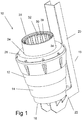
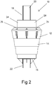
- a waste collection device 10 comprising a receptacle 12 provided for capturing waste from adjacent the surface of a body of water.
- the receptacle 12 in the embodiment shown is cylindrical such that the receptacle 12 comprises a cylindrical side wall 14 and a circular base wall 16.
- the cylindrical side wall 14 in the embodiment shown is tapered such that a lower end thereof is of a smaller diameter than an upper end thereof.
- the receptacle 12 is provided with a mounting frame 18, such that the receptacle 12 may be fixed at a location in a body of water such that upper end of the receptacle 12 is adjacent the surface of the water.
- the embodiment of Figures 1 to 4 may be suitable for fixing to a floating dock, such that the mounting frame 18 is fixed to the dock and the waste collection device 10 remains in a fixed position relative to the surface of the water as the floating dock moves.
- the mounting frame 18 comprises an elongate member 20 which extends vertically adjacent a vertical side of the side wall 14 of the receptacle 12.
- the frame 18 includes also an interconnecting portion 22 extending from a lower end of the elongate member 20 to connect with a lower surface of the base wall 16 of the receptacle 12.
- the elongate member 20 is to be fixed in use to the object to which the waste collection device 10 is to be mounted.
- the elongate member 20 and interconnecting portion 22 in the embodiment shown comprise elongate members having a U-shaped cross section.
- the waste collection device 10 includes an outlet (not shown) from which water may be pumped from the receptacle 12.
- the outlet comprises an opening in the base wall 16 of the receptacle 12.
- the waste collection device 10 includes a pump (also not shown) in connection with the outlet such that the pump operates to extract water from within the receptacle 12.
- the pump may be located externally and connected to the outlet via a conduit. Alternatively, the pump may be provided in or adjacent the receptacle 12 to pump water out through the outlet.
- the receptacle 12 defines an opening 24 in an upper end thereof.
- the receptacle 12 includes a top cover 26 securable to an upper end of the side wall 14 thereof.
- the top cover 26 is provided to engage across the open upper end of the cylindrical receptacle 12 and includes the opening 24.
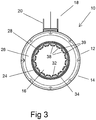
- the top cover 26 is annular in shape such that the opening 24 is a circular opening located centrally in the top cover 26.
- the waste collection device 10 includes also a tubular member 28.
- the tubular member 28 is dimensioned to be received within the opening 24 in the upper end of the receptacle 12 such that a central longitudinal axis of the tubular member 28 is coaxial with a central longitudinal axis of the receptacle 12.
- the tubular member 28 is arranged such that the tubular member 28 may slide upwardly or downwardly relative to the receptacle 12.
- An outer surface of the tubular member 28 engages with an inner surface of the opening 24 such that a seal is created and water may enter the receptacle 12 by passing through the tubular member 28.
- the tubular member 28 includes a rim 30 at a lower end thereof.
- the rim 30 extends outwardly from the periphery of the tubular member 28 at the lower end thereof.
- the rim 30 is provided to engage with the periphery of the opening 24 in the annular cover 26 when the tubular member 28 is in an uppermost position.
- the tubular member 28 comprises a cylindrical inner wall 32 and a cylindrical outer wall 34.
- the inner and outer walls 32 and 34 are coaxial and are connected at upper and lower ends thereof such that the inner and outer walls 32 and 34 define an annular chamber 36 within the tubular member 28.
- the annular chamber 36 provides buoyancy to the tubular member 28 and may be empty or filled with a buoyant material such as foam.
- the tubular member 28 is provided with a basket (not shown).
- the basket has an upper end secured adjacent the open upper end of the tubular member 28.
- the basket hangs inside the tubular member 28 and comprises a mesh material such that when water flows downwardly through the tubular member 28, the basket 28 captures waste material within the water and retains the waste material within the basket 28.
- the basket 28 may comprise a solid mesh frame or a flexible mesh bag.
- the basket comprises a hessian bag. It has been noted that hessian bags form a suitable filtering medium as the walls of the bag allow water to pass through and the fibres of the bag act to collect and thereby filter out smaller waste particles.
- the inner wall 32 of the tubular member 28 is provided with a plurality of ribs 38 thereon.
- the ribs 38 extend longitudinally down the inner surface of the inner wall 32 from a location adjacent the upper end of the tubular member 28.
- the inner and outer walls 32 and 34 may be formed from a plastic material and the ribs 38 formed integrally with the inner wall 32. In the embodiment shown, the ribs 38 are provided at equal angular spacings around the inner surface of the inner wall 32.
- the ribs 38 also define a plurality of elongate channels 39, each channel 39 being defined between a pair of adjacent ribs 38.
- the channels 39 defined by the ribs 38 allow flow of some water around the basket in the event that the basket has become blocked by collected waste. The channels 39 thereby reduce the likelihood of the pump running dry or damage being caused to the waste collection device 10 by the suction of the pump.
- the waste collection device 10 is located in a body of water such that the upper end of the receptacle 12 is adjacent and just below the surface of the water.
- the tubular member 28 falls downwardly until the upper end thereof is adjacent the surface of the water. Water then flows downwardly through the tubular member 28 and into the receptacle 12. As the water level in the receptacle 12 rises, the tubular member 28 moves upwardly, thereby restricting the flow of water into the receptacle 12. As the pump extracts water from within the receptacle 12, the volume of water flowing in through the tubular member 28 balances the water being pumped out.
- tubular member 28 Due to the buoyant nature of the tubular member 28 and its arrangement within the receptacle 12, should a wave (such as the wash from a boat) cause a sudden inflow of water into the tubular member 28, the tubular member 28 rises up out of the water to restrict further inward flow of water.
- a wave such as the wash from a boat
- the waste collection device 10 of Figures 1 to 4 may also be utilised in a location where it is anchored to the floor of the body of water, rather than connected to a floating object. In this case, the mounting frame 18 would be omitted.
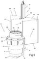
- FIGS 5 to 8 show a second embodiment of a waste collection device 10 in accordance with the present invention.
- the waste collection device 10 of Figures 5 to 8 is similar to the first embodiment and like reference numerals are used to denote like parts.
- the waste collection device 10 of Figures 5 to 8 is provided for mounting to a fixed location, such as a fixed dock or pylon.
- the elongate member 20 is mounted for sliding movement relative to a rail 40.
- the rail 40 is mounted vertically to the fixed location and to be received within the channel in the elongate member 20.
- a plurality of rollers are provided such that the elongate member 20 may slide vertically relative to the rail 40.
- the waste collection device 10 may therefore move upwardly or downwardly with changes in the position of the upper surface of the water relative to the object.
- the waste collection device 10 is also provided with a float 42.
- the float 42 comprises a hollow vessel mounted to the mounting frame.
- the vessel 43 includes an arcuate front surface 44 adjacent the receptacle 12, a planar rear surface 45 located remote from the receptacle 12, inwardly tapering side surfaces 46 and 47 and planar horizontal upper and lower surfaces 48 and 49.
- the rear surface 45 includes a channel 50 extending vertically therein such that the elongate member 20 and rail 40 are received within the channel 50.
- the float 42 is fillable with ballast to vary the buoyancy of the float 42.
- the waste collection device 10 is fitted to the rail 40 and the float 42 filled to a level to adjust the vertical position of the receptacle 12 to an appropriate position relative to the surface of the water. The waste collection device 10 then operates as described previously.
Description
- The present invention relates to a device for collection of waste from bodies of water.
- The amount of waste which finds its way into lakes, rivers and the oceans has become a significant environmental problem. The present invention relates to a device to be deployed within such bodies of water in order to collect floating waste for proper disposal.
- The device proposed in the applicant's earlier Spanish Patent number
201330495 -
US4325150 discloses a waste collection device according to the preamble of claim 1. This known device is embodied as a pool surface skimming apparatus which has two concentric, substantially cylindrical shells engageable one about the other. The inner shell has a floatation means integral therewith and a waste removal basket contained within its lower portion. The inner shell floats atop of the surface of the pool thus occasioning collection of solid matter from the pool's miniscus layer. The outer shell provides for the attachment of plumbing fixtures utilizable in the operation of the skimming apparatus. - According to the present invention there is provided a waste collection device according to claim 1.
- Preferably the tubular member is dimensioned to be received within the opening in the upper end of the receptacle such that a central longitudinal axis of the tubular member is coaxial with a central longitudinal axis of the receptacle.
- In a preferred embodiment, the tubular member includes a rim extending outwardly from the periphery of the tubular member at a lower end thereof such that the rim engages with the edge of the opening when the tubular member is in an uppermost position.
- Preferably the receptacle comprises a cylindrical side wall and a lower wall and wherein a top cover including the opening is securable to an upper end of the side wall of the receptacle.
- In a preferred embodiment, the top cover is annular in shape such that the opening is circular and located centrally in the top cover.
- Preferably the inner wall of the tubular member is provided with a plurality of ribs extending longitudinally down an inner surface thereof, the ribs defining a plurality of elongate channels such that some water may flow through the channels in the event that the basket is blocked.
- Preferably the ribs extend downwardly from adjacent the upper end of the inner wall of the tubular member.
- In one embodiment, the ribs are provided at equal angular spacings around the inner surface of the inner wall.
- In one embodiment, the receptacle includes a tapered cylindrical side wall such that a lower end thereof is of a smaller diameter than an upper end.
- Preferably a mounting frame is provided comprising an elongate member extending vertically adjacent the side wall of the receptacle and an interconnecting portion extending from a lower end of the elongate member to connect with a lower surface of the base wall of the receptacle.
- In one embodiment, the elongate member and interconnecting portion have U-shaped cross sections.
- In one embodiment, the elongate member is mounted for sliding movement relative to a fixed rail.
- In a further embodiment, a float is connected to the mounting frame, the float comprising a hollow vessel fillable with ballast to adjust the vertical position of the receptacle relative to the surface of the water.
- In one embodiment, the vessel includes an arcuate front surface adjacent the receptacle and a planar rear surface having a channel therein such that the elongate member and the rail are received within the channel.
- In one embodiment, the vessel includes inwardly tapering side surfaces and planar horizontal upper and lower surfaces.
- The invention will now be described, by way of example, with reference to the following drawings, in which:
-
Figure 1 is an upper perspective view of a waste collection device in accordance with the present invention; -
Figure 2 is a front view of the waste collection device ofFigure 1 ; -
Figure 3 is a top view of the waste collection device ofFigure 1 ; -
Figure 4 is a side cross-sectional view of the waste collection device ofFigure 1 ; -
Figure 5 is an upper perspective view of a second embodiment of a waste collection device in accordance with the present invention; -
Figure 6 is a front view of the waste collection device ofFigure 5 ; -
Figure 7 is a side view of the waste collection device ofFigure 5 ; and -
Figure 8 is a top view of the waste collection device ofFigure 5 . - Referring to the Figures, there is shown a
waste collection device 10 comprising areceptacle 12 provided for capturing waste from adjacent the surface of a body of water. - The
receptacle 12 in the embodiment shown is cylindrical such that thereceptacle 12 comprises acylindrical side wall 14 and acircular base wall 16. Thecylindrical side wall 14 in the embodiment shown is tapered such that a lower end thereof is of a smaller diameter than an upper end thereof. - The
receptacle 12 is provided with amounting frame 18, such that thereceptacle 12 may be fixed at a location in a body of water such that upper end of thereceptacle 12 is adjacent the surface of the water. The embodiment ofFigures 1 to 4 may be suitable for fixing to a floating dock, such that themounting frame 18 is fixed to the dock and thewaste collection device 10 remains in a fixed position relative to the surface of the water as the floating dock moves. - The
mounting frame 18 comprises anelongate member 20 which extends vertically adjacent a vertical side of theside wall 14 of thereceptacle 12. Theframe 18 includes also an interconnectingportion 22 extending from a lower end of theelongate member 20 to connect with a lower surface of thebase wall 16 of thereceptacle 12. Theelongate member 20 is to be fixed in use to the object to which thewaste collection device 10 is to be mounted. Theelongate member 20 and interconnectingportion 22 in the embodiment shown comprise elongate members having a U-shaped cross section. - The
waste collection device 10 includes an outlet (not shown) from which water may be pumped from thereceptacle 12. The outlet comprises an opening in thebase wall 16 of thereceptacle 12. Thewaste collection device 10 includes a pump (also not shown) in connection with the outlet such that the pump operates to extract water from within thereceptacle 12. The pump may be located externally and connected to the outlet via a conduit. Alternatively, the pump may be provided in or adjacent thereceptacle 12 to pump water out through the outlet. - The
receptacle 12 defines anopening 24 in an upper end thereof. Thereceptacle 12 includes atop cover 26 securable to an upper end of theside wall 14 thereof. Thetop cover 26 is provided to engage across the open upper end of thecylindrical receptacle 12 and includes the opening 24. In the embodiment shown, thetop cover 26 is annular in shape such that theopening 24 is a circular opening located centrally in thetop cover 26. - The
waste collection device 10 includes also atubular member 28. Thetubular member 28 is dimensioned to be received within the opening 24 in the upper end of thereceptacle 12 such that a central longitudinal axis of thetubular member 28 is coaxial with a central longitudinal axis of thereceptacle 12. Thetubular member 28 is arranged such that thetubular member 28 may slide upwardly or downwardly relative to thereceptacle 12. An outer surface of thetubular member 28 engages with an inner surface of theopening 24 such that a seal is created and water may enter thereceptacle 12 by passing through thetubular member 28. - The
tubular member 28 includes arim 30 at a lower end thereof. Therim 30 extends outwardly from the periphery of thetubular member 28 at the lower end thereof. Therim 30 is provided to engage with the periphery of theopening 24 in theannular cover 26 when thetubular member 28 is in an uppermost position. - The
tubular member 28 comprises a cylindricalinner wall 32 and a cylindricalouter wall 34. The inner andouter walls outer walls annular chamber 36 within thetubular member 28. Theannular chamber 36 provides buoyancy to thetubular member 28 and may be empty or filled with a buoyant material such as foam. - The
tubular member 28 is provided with a basket (not shown). The basket has an upper end secured adjacent the open upper end of thetubular member 28. The basket hangs inside thetubular member 28 and comprises a mesh material such that when water flows downwardly through thetubular member 28, thebasket 28 captures waste material within the water and retains the waste material within thebasket 28. - The
basket 28 may comprise a solid mesh frame or a flexible mesh bag. In one preferred embodiment, the basket comprises a hessian bag. It has been noted that hessian bags form a suitable filtering medium as the walls of the bag allow water to pass through and the fibres of the bag act to collect and thereby filter out smaller waste particles. - The
inner wall 32 of thetubular member 28 is provided with a plurality ofribs 38 thereon. Theribs 38 extend longitudinally down the inner surface of theinner wall 32 from a location adjacent the upper end of thetubular member 28. The inner andouter walls ribs 38 formed integrally with theinner wall 32. In the embodiment shown, theribs 38 are provided at equal angular spacings around the inner surface of theinner wall 32. - The
ribs 38 also define a plurality ofelongate channels 39, eachchannel 39 being defined between a pair ofadjacent ribs 38. Thechannels 39 defined by theribs 38 allow flow of some water around the basket in the event that the basket has become blocked by collected waste. Thechannels 39 thereby reduce the likelihood of the pump running dry or damage being caused to thewaste collection device 10 by the suction of the pump. - In use, the
waste collection device 10 is located in a body of water such that the upper end of thereceptacle 12 is adjacent and just below the surface of the water. When the interior of thereceptacle 12 is empty, thetubular member 28 falls downwardly until the upper end thereof is adjacent the surface of the water. Water then flows downwardly through thetubular member 28 and into thereceptacle 12. As the water level in thereceptacle 12 rises, thetubular member 28 moves upwardly, thereby restricting the flow of water into thereceptacle 12. As the pump extracts water from within thereceptacle 12, the volume of water flowing in through thetubular member 28 balances the water being pumped out. - Due to the buoyant nature of the
tubular member 28 and its arrangement within thereceptacle 12, should a wave (such as the wash from a boat) cause a sudden inflow of water into thetubular member 28, thetubular member 28 rises up out of the water to restrict further inward flow of water. - The
waste collection device 10 ofFigures 1 to 4 may also be utilised in a location where it is anchored to the floor of the body of water, rather than connected to a floating object. In this case, the mountingframe 18 would be omitted. -
Figures 5 to 8 show a second embodiment of awaste collection device 10 in accordance with the present invention. Thewaste collection device 10 ofFigures 5 to 8 is similar to the first embodiment and like reference numerals are used to denote like parts. - The
waste collection device 10 ofFigures 5 to 8 is provided for mounting to a fixed location, such as a fixed dock or pylon. Theelongate member 20 is mounted for sliding movement relative to arail 40. Therail 40 is mounted vertically to the fixed location and to be received within the channel in theelongate member 20. A plurality of rollers are provided such that theelongate member 20 may slide vertically relative to therail 40. Thewaste collection device 10 may therefore move upwardly or downwardly with changes in the position of the upper surface of the water relative to the object. - The
waste collection device 10 is also provided with afloat 42. Thefloat 42 comprises a hollow vessel mounted to the mounting frame. In the embodiment shown, thevessel 43 includes an arcuatefront surface 44 adjacent thereceptacle 12, a planarrear surface 45 located remote from thereceptacle 12, inwardly tapering side surfaces 46 and 47 and planar horizontal upper andlower surfaces rear surface 45 includes achannel 50 extending vertically therein such that theelongate member 20 andrail 40 are received within thechannel 50. - The
float 42 is fillable with ballast to vary the buoyancy of thefloat 42. In use, thewaste collection device 10 is fitted to therail 40 and thefloat 42 filled to a level to adjust the vertical position of thereceptacle 12 to an appropriate position relative to the surface of the water. Thewaste collection device 10 then operates as described previously. - It will be readily apparent to persons skilled in the relevant arts that various modifications and improvements may be made to the foregoing embodiments, in addition to those already described, without departing from the scope of the invention as defined by the appended claims.
Claims (15)
- A waste collection device (10) comprising;
a receptacle (12) having an opening (24) in an upper end, the receptacle (12) being mounted relative to a body of water such that the upper end is adjacent a surface of the water;
a tubular member (28) mounted for sliding movement within the opening (24);
a pump for pumping water outwardly from within the receptacle (12); and
a basket within the tubular member (28) for extracting waste from water passing through the tubular member (28);
wherein the tubular member (28) comprises a cylindrical inner wall (32) and a cylindrical outer wall (34), and wherein an outer surface of the tubular member (28) engages with an inner surface of the opening such that a seal is created and water may enter the receptacle (12) by passing through the tubular member (28),
characterized in that the cylindrical inner wall (32) and the cylindrical outer wall (34) are connected at upper and lower ends thereof to define an annular chamber (36) to provide buoyancy to the tubular member (28). - A waste collection device (10) in accordance with claim 1, wherein the tubular member (28) is dimensioned to be received within the opening in the upper end of the receptacle (12) such that a central longitudinal axis of the tubular member (28) is coaxial with a central longitudinal axis of the receptacle (12).
- A waste collection device (10) in accordance with claim 1, wherein the tubular member (28) includes a rim (30) extending outwardly from the periphery of the tubular member (28) at a lower end thereof such that the rim (30) engages with the edge of the opening (24) when the tubular member (28) is in an uppermost position.
- A waste collection device (10) in accordance with any one of the preceding claims, wherein the receptacle (12) comprises a cylindrical side wall (14) and a lower wall and wherein a top cover (26) including the opening is securable to an upper end of the side wall (14) of the receptacle (12).
- A waste collection device (10) in accordance with claim 4, wherein the top cover (26) is annular in shape such that the opening (24) is circular and located centrally in the top cover (26).
- A waste collection device (10) in accordance with any one of the preceding claims, wherein the inner wall (32) of the tubular member (28) is provided with a plurality of ribs (38) extending longitudinally down an inner surface thereof, the ribs (38) defining a plurality of elongate channels (39) such that some water may flow through the channels (39) in the event that the basket is blocked.
- A waste collection device (10) in accordance with claim 6, wherein the ribs (38) extend downwardly from adjacent the upper end of the inner wall (32) of the tubular member (28).
- A waste collection in accordance with claim 7, wherein the ribs (38) are provided at equal angular spacings around the inner surface of the inner wall (32).
- A waste collection device (10) in accordance with any one of the preceding claims, wherein the receptacle (12) includes a tapered cylindrical side wall (14) such that a lower end thereof is of a smaller diameter than an upper end.
- A waste collection device (10) in accordance with any one of the preceding claims, wherein a mounting frame (18) is provided comprising an elongate member (20) extending vertically adjacent the side wall (14) of the receptacle (12) and an interconnecting portion (22) extending from a lower end of the elongate member (20) to connect with a lower surface of the base wall of the receptacle (12).
- A waste collection device (10) in accordance with claim 10, wherein the elongate member (20) and interconnecting portion (22) have U-shaped cross sections.
- A waste collection device (10) in accordance with claim 10 or 11, wherein the elongate member (20) is mounted for sliding movement relative to a fixed rail (40).
- A waste collection device (10) in accordance with any one of claims 10 to 12, wherein a float (42) is connected to the mounting frame (18), the float (42) comprising a hollow vessel (43) fillable with ballast to adjust the vertical position of the receptacle (12) relative to the surface of the water.
- A waste collection device (10) in accordance with claim 13, wherein the vessel (43) includes an arcuate front surface (44) adjacent the receptacle (12) and a planar rear surface (45) having a channel (50) therein such that the elongate member (20) and the rail (40) are received within the channel (50).
- A waste collection device (10) in accordance with claim 14, wherein the vessel (43) includes inwardly tapering side surfaces (46, 17) and planar horizontal upper and lower surfaces (48, 49).
Applications Claiming Priority (2)
| Application Number | Priority Date | Filing Date | Title |
|---|---|---|---|
| AU2016905066A AU2016905066A0 (en) | 2016-12-08 | Waste Collection Device | |
| PCT/AU2017/051339 WO2018102869A1 (en) | 2016-12-08 | 2017-12-06 | Waste collection device |
Publications (3)
| Publication Number | Publication Date |
|---|---|
| EP3551805A1 EP3551805A1 (en) | 2019-10-16 |
| EP3551805A4 EP3551805A4 (en) | 2019-11-27 |
| EP3551805B1 true EP3551805B1 (en) | 2021-02-24 |
Family
ID=62490563
Family Applications (1)
| Application Number | Title | Priority Date | Filing Date |
|---|---|---|---|
| EP17879375.8A Active EP3551805B1 (en) | 2016-12-08 | 2017-12-06 | Waste collection device |
Country Status (8)
| Country | Link |
|---|---|
| US (1) | US10954642B2 (en) |
| EP (1) | EP3551805B1 (en) |
| JP (1) | JP7262777B2 (en) |
| AU (1) | AU2017371713B2 (en) |
| DK (1) | DK3551805T3 (en) |
| ES (1) | ES2874302T3 (en) |
| PT (1) | PT3551805T (en) |
| WO (1) | WO2018102869A1 (en) |
Families Citing this family (10)
| Publication number | Priority date | Publication date | Assignee | Title |
|---|---|---|---|---|
| CN108792345B (en) * | 2018-07-11 | 2023-08-11 | 深圳市众致环保科技有限公司 | Automatic recovery system of ocean rubbish |
| CN109533211B (en) * | 2018-10-26 | 2021-04-02 | 上海交通大学 | Pump suction filtering type intelligent robot for cleaning water body garbage and control method |
| FI130238B (en) * | 2018-11-15 | 2023-05-04 | Clewat Oy | A device for collecting waste from water |
| CN110630053A (en) * | 2019-09-28 | 2019-12-31 | 浦江县力顶环保设备有限公司 | Collection device suitable for outdoor swimming pool surface refuse treatment |
| FR3102999B1 (en) | 2019-11-08 | 2021-10-22 | Ylec Consultants | Device for recovering liquid and / or solid products supernatant on the surface of a body of water. |
| US11414825B2 (en) * | 2020-02-27 | 2022-08-16 | Mirza Faizan | Apparatus and method to clean garbage from water bodies |
| CN112081082A (en) * | 2020-08-25 | 2020-12-15 | 广州太和水生态科技有限公司 | Device for extracting floating garbage on water surface |
| US11414824B2 (en) * | 2021-03-05 | 2022-08-16 | Jarrett Bryzek | Water surface debris collector |
| CN113232787A (en) * | 2021-06-09 | 2021-08-10 | 上海电机学院 | Fish swallowing type water surface garbage cleaning robot |
| JP7426365B2 (en) | 2021-11-04 | 2024-02-01 | ヤマハ発動機株式会社 | garbage collection boat |
Family Cites Families (13)
| Publication number | Priority date | Publication date | Assignee | Title |
|---|---|---|---|---|
| US3970556A (en) * | 1974-09-23 | 1976-07-20 | Douglas John Gore | Floating skimmer for cleaning the surface of a body of liquid, method and apparatus |
| US4325150A (en) * | 1980-09-22 | 1982-04-20 | Buddy H E | Pool surface skimming apparatus |
| IT1233081B (en) * | 1989-08-08 | 1992-03-14 | Gi Pi S A S Di Alfonso Gallett | BLUSHING DEVICE FOR CONTAINMENT TANKS OF RANTI REFRIGE FLUIDS WITH SUSPENSION OILS FOR OIL REMOVERS |
| ES2056722B1 (en) * | 1992-06-09 | 1995-04-16 | Carro Fco Javier Jauregui | IMPROVEMENTS INTRODUCED IN CONTROLLED FLOATING VACUUM SYSTEMS. |
| JP2635482B2 (en) * | 1992-06-22 | 1997-07-30 | 広和機械設計工業株式会社 | Surface liquid discharge device |
| FR2787819B1 (en) * | 1998-12-24 | 2001-03-02 | Sevylor Internat | FLOATING DEVICE FOR COLLECTING WATER ON THE SURFACE OF A BASIN FOR A PUMP INSTALLATION |
| US6159362A (en) * | 1999-09-07 | 2000-12-12 | Gilmore; Ronald N. | Skimmer valve |
| FR2831193B1 (en) * | 2001-10-18 | 2004-02-13 | Robert Rebujent | DEVICE FOR NATURALLY COLLECTING FLOATING OBJECTS ON THE SURFACE OF BODIES OF WATER |
| US6709582B2 (en) * | 2002-04-22 | 2004-03-23 | Michael Danner | Combined filter and skimmer assembly for ponds |
| US8231780B2 (en) * | 2007-12-27 | 2012-07-31 | Happel Thomas H | Floating skimmer and filter apparatus |
| ES1080807Y (en) * | 2013-04-24 | 2013-08-30 | Andrew Stephen Turton | FLOATING GARBAGE COLLECTION DEVICE |
| US10260247B2 (en) * | 2014-02-28 | 2019-04-16 | Waterdrop Enterprises, Llc | Floating weir basket for use in pool skimmers |
| WO2017139855A1 (en) * | 2016-02-18 | 2017-08-24 | Seabin Pty Ltd | Waste collection device |
-
2017
- 2017-12-06 WO PCT/AU2017/051339 patent/WO2018102869A1/en active Search and Examination
- 2017-12-06 US US16/468,211 patent/US10954642B2/en active Active
- 2017-12-06 ES ES17879375T patent/ES2874302T3/en active Active
- 2017-12-06 JP JP2019552314A patent/JP7262777B2/en active Active
- 2017-12-06 EP EP17879375.8A patent/EP3551805B1/en active Active
- 2017-12-06 PT PT178793758T patent/PT3551805T/en unknown
- 2017-12-06 DK DK17879375.8T patent/DK3551805T3/en active
- 2017-12-06 AU AU2017371713A patent/AU2017371713B2/en active Active
Non-Patent Citations (1)
| Title |
|---|
| None * |
Also Published As
| Publication number | Publication date |
|---|---|
| US10954642B2 (en) | 2021-03-23 |
| PT3551805T (en) | 2021-05-27 |
| EP3551805A1 (en) | 2019-10-16 |
| JP2020500709A (en) | 2020-01-16 |
| AU2017371713B2 (en) | 2023-10-26 |
| DK3551805T3 (en) | 2021-05-31 |
| AU2017371713A1 (en) | 2019-07-11 |
| US20200011020A1 (en) | 2020-01-09 |
| JP7262777B2 (en) | 2023-04-24 |
| WO2018102869A1 (en) | 2018-06-14 |
| EP3551805A4 (en) | 2019-11-27 |
| ES2874302T3 (en) | 2021-11-04 |
Similar Documents
| Publication | Publication Date | Title |
|---|---|---|
| EP3551805B1 (en) | Waste collection device | |
| KR101024970B1 (en) | Separating apparatus of water and oil | |
| US4325150A (en) | Pool surface skimming apparatus | |
| EP1206601B1 (en) | Apparatus for collecting material floating on a body of water | |
| KR100715286B1 (en) | Whirl type separator with filter | |
| WO2017139855A1 (en) | Waste collection device | |
| EP1027502B1 (en) | Method and apparatus for separating floating pollutants | |
| KR102197606B1 (en) | Apparatus of collecting float and preventing Algae | |
| KR100938411B1 (en) | Apparatus for removing floating matters | |
| KR101737268B1 (en) | Noise prevention device of water drops | |
| US6251266B1 (en) | Suction tube inlet with strainer | |
| JP5193151B2 (en) | Solid-liquid separation device and water treatment device | |
| US9453354B1 (en) | Method and apparatus to prevent excessive suction in venturi-type swimming pool skimmers | |
| US9447595B1 (en) | Systems, methods and apparatuses for relieving excessive suction within swimming pool skimmers | |
| ES1080807U (en) | Floating garbage device device (Machine-translation by Google Translate, not legally binding) | |
| ES2200100T3 (en) | DEVICE FOR THE ABSORPTION OF A LAYER OF A LIGHT LIQUID. | |
| GB2257051A (en) | Skimming apparatus | |
| CN212358532U (en) | Floating ball floor drain with anti-reflux function | |
| KR101285727B1 (en) | Apparatus for preventing inflow of foreign | |
| CN210177476U (en) | Filtering device for coastal floating garbage | |
| CN209992235U (en) | Shallow water area water sampling device and water quality monitoring system | |
| JP2003039066A (en) | Floating oil recovering device | |
| KR20170061810A (en) | Oil separator | |
| KR20170042860A (en) | Structure of filter box for drainage in collecting well | |
| JPS587355B2 (en) | Fuyuyunobunrikaishyuusouchi |
Legal Events
| Date | Code | Title | Description |
|---|---|---|---|
| STAA | Information on the status of an ep patent application or granted ep patent |
Free format text: STATUS: THE INTERNATIONAL PUBLICATION HAS BEEN MADE |
|
| PUAI | Public reference made under article 153(3) epc to a published international application that has entered the european phase |
Free format text: ORIGINAL CODE: 0009012 |
|
| STAA | Information on the status of an ep patent application or granted ep patent |
Free format text: STATUS: REQUEST FOR EXAMINATION WAS MADE |
|
| 17P | Request for examination filed |
Effective date: 20190705 |
|
| AK | Designated contracting states |
Kind code of ref document: A1 Designated state(s): AL AT BE BG CH CY CZ DE DK EE ES FI FR GB GR HR HU IE IS IT LI LT LU LV MC MK MT NL NO PL PT RO RS SE SI SK SM TR |
|
| AX | Request for extension of the european patent |
Extension state: BA ME |
|
| A4 | Supplementary search report drawn up and despatched |
Effective date: 20191028 |
|
| RIC1 | Information provided on ipc code assigned before grant |
Ipc: E04H 4/16 20060101ALI20191022BHEP Ipc: B01D 35/00 20060101ALI20191022BHEP Ipc: E02B 15/04 20060101AFI20191022BHEP Ipc: B01D 35/05 20060101ALI20191022BHEP Ipc: E02B 15/10 20060101ALI20191022BHEP Ipc: C02F 1/24 20060101ALI20191022BHEP Ipc: B63B 35/32 20060101ALI20191022BHEP Ipc: C02F 1/00 20060101ALI20191022BHEP Ipc: E04H 4/12 20060101ALI20191022BHEP |
|
| RIN1 | Information on inventor provided before grant (corrected) |
Inventor name: CEGLINSKI, PETER |
|
| DAV | Request for validation of the european patent (deleted) | ||
| DAX | Request for extension of the european patent (deleted) | ||
| GRAP | Despatch of communication of intention to grant a patent |
Free format text: ORIGINAL CODE: EPIDOSNIGR1 |
|
| STAA | Information on the status of an ep patent application or granted ep patent |
Free format text: STATUS: GRANT OF PATENT IS INTENDED |
|
| INTG | Intention to grant announced |
Effective date: 20200911 |
|
| GRAS | Grant fee paid |
Free format text: ORIGINAL CODE: EPIDOSNIGR3 |
|
| GRAA | (expected) grant |
Free format text: ORIGINAL CODE: 0009210 |
|
| STAA | Information on the status of an ep patent application or granted ep patent |
Free format text: STATUS: THE PATENT HAS BEEN GRANTED |
|
| AK | Designated contracting states |
Kind code of ref document: B1 Designated state(s): AL AT BE BG CH CY CZ DE DK EE ES FI FR GB GR HR HU IE IS IT LI LT LU LV MC MK MT NL NO PL PT RO RS SE SI SK SM TR |
|
| REG | Reference to a national code |
Ref country code: CH Ref legal event code: EP |
|
| REG | Reference to a national code |
Ref country code: AT Ref legal event code: REF Ref document number: 1364589 Country of ref document: AT Kind code of ref document: T Effective date: 20210315 |
|
| REG | Reference to a national code |
Ref country code: IE Ref legal event code: FG4D |
|
| REG | Reference to a national code |
Ref country code: DE Ref legal event code: R096 Ref document number: 602017033566 Country of ref document: DE |
|
| REG | Reference to a national code |
Ref country code: FI Ref legal event code: FGE |
|
| REG | Reference to a national code |
Ref country code: PT Ref legal event code: SC4A Ref document number: 3551805 Country of ref document: PT Date of ref document: 20210527 Kind code of ref document: T Free format text: AVAILABILITY OF NATIONAL TRANSLATION Effective date: 20210519 |
|
| REG | Reference to a national code |
Ref country code: DK Ref legal event code: T3 Effective date: 20210525 Ref country code: NO Ref legal event code: T2 Effective date: 20210224 |
|
| REG | Reference to a national code |
Ref country code: NL Ref legal event code: FP |
|
| REG | Reference to a national code |
Ref country code: SE Ref legal event code: TRGR |
|
| REG | Reference to a national code |
Ref country code: LT Ref legal event code: MG9D |
|
| REG | Reference to a national code |
Ref country code: GR Ref legal event code: EP Ref document number: 20210401331 Country of ref document: GR Effective date: 20210709 |
|
| PG25 | Lapsed in a contracting state [announced via postgrant information from national office to epo] |
Ref country code: HR Free format text: LAPSE BECAUSE OF FAILURE TO SUBMIT A TRANSLATION OF THE DESCRIPTION OR TO PAY THE FEE WITHIN THE PRESCRIBED TIME-LIMIT Effective date: 20210224 Ref country code: BG Free format text: LAPSE BECAUSE OF FAILURE TO SUBMIT A TRANSLATION OF THE DESCRIPTION OR TO PAY THE FEE WITHIN THE PRESCRIBED TIME-LIMIT Effective date: 20210524 Ref country code: LT Free format text: LAPSE BECAUSE OF FAILURE TO SUBMIT A TRANSLATION OF THE DESCRIPTION OR TO PAY THE FEE WITHIN THE PRESCRIBED TIME-LIMIT Effective date: 20210224 |
|
| REG | Reference to a national code |
Ref country code: AT Ref legal event code: MK05 Ref document number: 1364589 Country of ref document: AT Kind code of ref document: T Effective date: 20210224 |
|
| PG25 | Lapsed in a contracting state [announced via postgrant information from national office to epo] |
Ref country code: PL Free format text: LAPSE BECAUSE OF FAILURE TO SUBMIT A TRANSLATION OF THE DESCRIPTION OR TO PAY THE FEE WITHIN THE PRESCRIBED TIME-LIMIT Effective date: 20210224 Ref country code: LV Free format text: LAPSE BECAUSE OF FAILURE TO SUBMIT A TRANSLATION OF THE DESCRIPTION OR TO PAY THE FEE WITHIN THE PRESCRIBED TIME-LIMIT Effective date: 20210224 Ref country code: RS Free format text: LAPSE BECAUSE OF FAILURE TO SUBMIT A TRANSLATION OF THE DESCRIPTION OR TO PAY THE FEE WITHIN THE PRESCRIBED TIME-LIMIT Effective date: 20210224 |
|
| PG25 | Lapsed in a contracting state [announced via postgrant information from national office to epo] |
Ref country code: IS Free format text: LAPSE BECAUSE OF FAILURE TO SUBMIT A TRANSLATION OF THE DESCRIPTION OR TO PAY THE FEE WITHIN THE PRESCRIBED TIME-LIMIT Effective date: 20210624 |
|
| PG25 | Lapsed in a contracting state [announced via postgrant information from national office to epo] |
Ref country code: CZ Free format text: LAPSE BECAUSE OF FAILURE TO SUBMIT A TRANSLATION OF THE DESCRIPTION OR TO PAY THE FEE WITHIN THE PRESCRIBED TIME-LIMIT Effective date: 20210224 Ref country code: EE Free format text: LAPSE BECAUSE OF FAILURE TO SUBMIT A TRANSLATION OF THE DESCRIPTION OR TO PAY THE FEE WITHIN THE PRESCRIBED TIME-LIMIT Effective date: 20210224 Ref country code: SM Free format text: LAPSE BECAUSE OF FAILURE TO SUBMIT A TRANSLATION OF THE DESCRIPTION OR TO PAY THE FEE WITHIN THE PRESCRIBED TIME-LIMIT Effective date: 20210224 Ref country code: AT Free format text: LAPSE BECAUSE OF FAILURE TO SUBMIT A TRANSLATION OF THE DESCRIPTION OR TO PAY THE FEE WITHIN THE PRESCRIBED TIME-LIMIT Effective date: 20210224 |
|
| REG | Reference to a national code |
Ref country code: DE Ref legal event code: R097 Ref document number: 602017033566 Country of ref document: DE |
|
| PG25 | Lapsed in a contracting state [announced via postgrant information from national office to epo] |
Ref country code: SK Free format text: LAPSE BECAUSE OF FAILURE TO SUBMIT A TRANSLATION OF THE DESCRIPTION OR TO PAY THE FEE WITHIN THE PRESCRIBED TIME-LIMIT Effective date: 20210224 Ref country code: RO Free format text: LAPSE BECAUSE OF FAILURE TO SUBMIT A TRANSLATION OF THE DESCRIPTION OR TO PAY THE FEE WITHIN THE PRESCRIBED TIME-LIMIT Effective date: 20210224 |
|
| PLBE | No opposition filed within time limit |
Free format text: ORIGINAL CODE: 0009261 |
|
| STAA | Information on the status of an ep patent application or granted ep patent |
Free format text: STATUS: NO OPPOSITION FILED WITHIN TIME LIMIT |
|
| PG25 | Lapsed in a contracting state [announced via postgrant information from national office to epo] |
Ref country code: AL Free format text: LAPSE BECAUSE OF FAILURE TO SUBMIT A TRANSLATION OF THE DESCRIPTION OR TO PAY THE FEE WITHIN THE PRESCRIBED TIME-LIMIT Effective date: 20210224 |
|
| 26N | No opposition filed |
Effective date: 20211125 |
|
| PG25 | Lapsed in a contracting state [announced via postgrant information from national office to epo] |
Ref country code: SI Free format text: LAPSE BECAUSE OF FAILURE TO SUBMIT A TRANSLATION OF THE DESCRIPTION OR TO PAY THE FEE WITHIN THE PRESCRIBED TIME-LIMIT Effective date: 20210224 |
|
| PG25 | Lapsed in a contracting state [announced via postgrant information from national office to epo] |
Ref country code: IS Free format text: LAPSE BECAUSE OF FAILURE TO SUBMIT A TRANSLATION OF THE DESCRIPTION OR TO PAY THE FEE WITHIN THE PRESCRIBED TIME-LIMIT Effective date: 20210624 |
|
| PG25 | Lapsed in a contracting state [announced via postgrant information from national office to epo] |
Ref country code: MC Free format text: LAPSE BECAUSE OF FAILURE TO SUBMIT A TRANSLATION OF THE DESCRIPTION OR TO PAY THE FEE WITHIN THE PRESCRIBED TIME-LIMIT Effective date: 20210224 |
|
| REG | Reference to a national code |
Ref country code: CH Ref legal event code: PL |
|
| REG | Reference to a national code |
Ref country code: BE Ref legal event code: MM Effective date: 20211231 |
|
| PG25 | Lapsed in a contracting state [announced via postgrant information from national office to epo] |
Ref country code: LU Free format text: LAPSE BECAUSE OF NON-PAYMENT OF DUE FEES Effective date: 20211206 |
|
| PG25 | Lapsed in a contracting state [announced via postgrant information from national office to epo] |
Ref country code: BE Free format text: LAPSE BECAUSE OF NON-PAYMENT OF DUE FEES Effective date: 20211231 |
|
| PG25 | Lapsed in a contracting state [announced via postgrant information from national office to epo] |
Ref country code: LI Free format text: LAPSE BECAUSE OF NON-PAYMENT OF DUE FEES Effective date: 20211231 Ref country code: CH Free format text: LAPSE BECAUSE OF NON-PAYMENT OF DUE FEES Effective date: 20211231 |
|
| PGFP | Annual fee paid to national office [announced via postgrant information from national office to epo] |
Ref country code: SE Payment date: 20221222 Year of fee payment: 6 Ref country code: PT Payment date: 20221202 Year of fee payment: 6 Ref country code: NO Payment date: 20221227 Year of fee payment: 6 Ref country code: NL Payment date: 20221222 Year of fee payment: 6 Ref country code: IE Payment date: 20221222 Year of fee payment: 6 Ref country code: FI Payment date: 20221222 Year of fee payment: 6 Ref country code: DK Payment date: 20221223 Year of fee payment: 6 Ref country code: DE Payment date: 20221213 Year of fee payment: 6 |
|
| PGFP | Annual fee paid to national office [announced via postgrant information from national office to epo] |
Ref country code: GR Payment date: 20221223 Year of fee payment: 6 |
|
| PGFP | Annual fee paid to national office [announced via postgrant information from national office to epo] |
Ref country code: ES Payment date: 20230228 Year of fee payment: 6 |
|
| PGFP | Annual fee paid to national office [announced via postgrant information from national office to epo] |
Ref country code: IT Payment date: 20221228 Year of fee payment: 6 |
|
| PG25 | Lapsed in a contracting state [announced via postgrant information from national office to epo] |
Ref country code: CY Free format text: LAPSE BECAUSE OF FAILURE TO SUBMIT A TRANSLATION OF THE DESCRIPTION OR TO PAY THE FEE WITHIN THE PRESCRIBED TIME-LIMIT Effective date: 20210224 |
|
| PG25 | Lapsed in a contracting state [announced via postgrant information from national office to epo] |
Ref country code: HU Free format text: LAPSE BECAUSE OF FAILURE TO SUBMIT A TRANSLATION OF THE DESCRIPTION OR TO PAY THE FEE WITHIN THE PRESCRIBED TIME-LIMIT; INVALID AB INITIO Effective date: 20171206 |
|
| PGFP | Annual fee paid to national office [announced via postgrant information from national office to epo] |
Ref country code: GB Payment date: 20231220 Year of fee payment: 7 |
|
| PGFP | Annual fee paid to national office [announced via postgrant information from national office to epo] |
Ref country code: FR Payment date: 20231222 Year of fee payment: 7 |