EP3551782B1 - Structure de support d'électrodes pour cellules électrolytiques coaxiales - Google Patents
Structure de support d'électrodes pour cellules électrolytiques coaxiales Download PDFInfo
- Publication number
- EP3551782B1 EP3551782B1 EP17826281.2A EP17826281A EP3551782B1 EP 3551782 B1 EP3551782 B1 EP 3551782B1 EP 17826281 A EP17826281 A EP 17826281A EP 3551782 B1 EP3551782 B1 EP 3551782B1
- Authority
- EP
- European Patent Office
- Prior art keywords
- housing
- electrodes
- support structure
- partition member
- plane
- Prior art date
- Legal status (The legal status is an assumption and is not a legal conclusion. Google has not performed a legal analysis and makes no representation as to the accuracy of the status listed.)
- Active
Links
Images




Classifications
-
- C—CHEMISTRY; METALLURGY
- C25—ELECTROLYTIC OR ELECTROPHORETIC PROCESSES; APPARATUS THEREFOR
- C25B—ELECTROLYTIC OR ELECTROPHORETIC PROCESSES FOR THE PRODUCTION OF COMPOUNDS OR NON-METALS; APPARATUS THEREFOR
- C25B15/00—Operating or servicing cells
- C25B15/08—Supplying or removing reactants or electrolytes; Regeneration of electrolytes
-
- C—CHEMISTRY; METALLURGY
- C02—TREATMENT OF WATER, WASTE WATER, SEWAGE, OR SLUDGE
- C02F—TREATMENT OF WATER, WASTE WATER, SEWAGE, OR SLUDGE
- C02F1/00—Treatment of water, waste water, or sewage
- C02F1/46—Treatment of water, waste water, or sewage by electrochemical methods
- C02F1/461—Treatment of water, waste water, or sewage by electrochemical methods by electrolysis
- C02F1/46104—Devices therefor; Their operating or servicing
-
- C—CHEMISTRY; METALLURGY
- C25—ELECTROLYTIC OR ELECTROPHORETIC PROCESSES; APPARATUS THEREFOR
- C25B—ELECTROLYTIC OR ELECTROPHORETIC PROCESSES FOR THE PRODUCTION OF COMPOUNDS OR NON-METALS; APPARATUS THEREFOR
- C25B11/00—Electrodes; Manufacture thereof not otherwise provided for
- C25B11/02—Electrodes; Manufacture thereof not otherwise provided for characterised by shape or form
-
- C—CHEMISTRY; METALLURGY
- C25—ELECTROLYTIC OR ELECTROPHORETIC PROCESSES; APPARATUS THEREFOR
- C25B—ELECTROLYTIC OR ELECTROPHORETIC PROCESSES FOR THE PRODUCTION OF COMPOUNDS OR NON-METALS; APPARATUS THEREFOR
- C25B13/00—Diaphragms; Spacing elements
- C25B13/02—Diaphragms; Spacing elements characterised by shape or form
-
- C—CHEMISTRY; METALLURGY
- C25—ELECTROLYTIC OR ELECTROPHORETIC PROCESSES; APPARATUS THEREFOR
- C25B—ELECTROLYTIC OR ELECTROPHORETIC PROCESSES FOR THE PRODUCTION OF COMPOUNDS OR NON-METALS; APPARATUS THEREFOR
- C25B15/00—Operating or servicing cells
- C25B15/02—Process control or regulation
-
- C—CHEMISTRY; METALLURGY
- C25—ELECTROLYTIC OR ELECTROPHORETIC PROCESSES; APPARATUS THEREFOR
- C25B—ELECTROLYTIC OR ELECTROPHORETIC PROCESSES FOR THE PRODUCTION OF COMPOUNDS OR NON-METALS; APPARATUS THEREFOR
- C25B15/00—Operating or servicing cells
- C25B15/08—Supplying or removing reactants or electrolytes; Regeneration of electrolytes
- C25B15/087—Recycling of electrolyte to electrochemical cell
-
- C—CHEMISTRY; METALLURGY
- C25—ELECTROLYTIC OR ELECTROPHORETIC PROCESSES; APPARATUS THEREFOR
- C25B—ELECTROLYTIC OR ELECTROPHORETIC PROCESSES FOR THE PRODUCTION OF COMPOUNDS OR NON-METALS; APPARATUS THEREFOR
- C25B9/00—Cells or assemblies of cells; Constructional parts of cells; Assemblies of constructional parts, e.g. electrode-diaphragm assemblies; Process-related cell features
- C25B9/17—Cells comprising dimensionally-stable non-movable electrodes; Assemblies of constructional parts thereof
-
- C—CHEMISTRY; METALLURGY
- C25—ELECTROLYTIC OR ELECTROPHORETIC PROCESSES; APPARATUS THEREFOR
- C25B—ELECTROLYTIC OR ELECTROPHORETIC PROCESSES FOR THE PRODUCTION OF COMPOUNDS OR NON-METALS; APPARATUS THEREFOR
- C25B9/00—Cells or assemblies of cells; Constructional parts of cells; Assemblies of constructional parts, e.g. electrode-diaphragm assemblies; Process-related cell features
- C25B9/17—Cells comprising dimensionally-stable non-movable electrodes; Assemblies of constructional parts thereof
- C25B9/19—Cells comprising dimensionally-stable non-movable electrodes; Assemblies of constructional parts thereof with diaphragms
-
- C—CHEMISTRY; METALLURGY
- C25—ELECTROLYTIC OR ELECTROPHORETIC PROCESSES; APPARATUS THEREFOR
- C25B—ELECTROLYTIC OR ELECTROPHORETIC PROCESSES FOR THE PRODUCTION OF COMPOUNDS OR NON-METALS; APPARATUS THEREFOR
- C25B9/00—Cells or assemblies of cells; Constructional parts of cells; Assemblies of constructional parts, e.g. electrode-diaphragm assemblies; Process-related cell features
- C25B9/60—Constructional parts of cells
- C25B9/63—Holders for electrodes; Positioning of the electrodes
-
- C—CHEMISTRY; METALLURGY
- C25—ELECTROLYTIC OR ELECTROPHORETIC PROCESSES; APPARATUS THEREFOR
- C25B—ELECTROLYTIC OR ELECTROPHORETIC PROCESSES FOR THE PRODUCTION OF COMPOUNDS OR NON-METALS; APPARATUS THEREFOR
- C25B9/00—Cells or assemblies of cells; Constructional parts of cells; Assemblies of constructional parts, e.g. electrode-diaphragm assemblies; Process-related cell features
- C25B9/70—Assemblies comprising two or more cells
-
- C—CHEMISTRY; METALLURGY
- C25—ELECTROLYTIC OR ELECTROPHORETIC PROCESSES; APPARATUS THEREFOR
- C25B—ELECTROLYTIC OR ELECTROPHORETIC PROCESSES FOR THE PRODUCTION OF COMPOUNDS OR NON-METALS; APPARATUS THEREFOR
- C25B9/00—Cells or assemblies of cells; Constructional parts of cells; Assemblies of constructional parts, e.g. electrode-diaphragm assemblies; Process-related cell features
- C25B9/70—Assemblies comprising two or more cells
- C25B9/73—Assemblies comprising two or more cells of the filter-press type
- C25B9/75—Assemblies comprising two or more cells of the filter-press type having bipolar electrodes
-
- C—CHEMISTRY; METALLURGY
- C25—ELECTROLYTIC OR ELECTROPHORETIC PROCESSES; APPARATUS THEREFOR
- C25C—PROCESSES FOR THE ELECTROLYTIC PRODUCTION, RECOVERY OR REFINING OF METALS; APPARATUS THEREFOR
- C25C7/00—Constructional parts, or assemblies thereof, of cells; Servicing or operating of cells
-
- C—CHEMISTRY; METALLURGY
- C25—ELECTROLYTIC OR ELECTROPHORETIC PROCESSES; APPARATUS THEREFOR
- C25C—PROCESSES FOR THE ELECTROLYTIC PRODUCTION, RECOVERY OR REFINING OF METALS; APPARATUS THEREFOR
- C25C7/00—Constructional parts, or assemblies thereof, of cells; Servicing or operating of cells
- C25C7/02—Electrodes; Connections thereof
-
- C—CHEMISTRY; METALLURGY
- C25—ELECTROLYTIC OR ELECTROPHORETIC PROCESSES; APPARATUS THEREFOR
- C25C—PROCESSES FOR THE ELECTROLYTIC PRODUCTION, RECOVERY OR REFINING OF METALS; APPARATUS THEREFOR
- C25C7/00—Constructional parts, or assemblies thereof, of cells; Servicing or operating of cells
- C25C7/04—Diaphragms; Spacing elements
-
- C—CHEMISTRY; METALLURGY
- C02—TREATMENT OF WATER, WASTE WATER, SEWAGE, OR SLUDGE
- C02F—TREATMENT OF WATER, WASTE WATER, SEWAGE, OR SLUDGE
- C02F1/00—Treatment of water, waste water, or sewage
- C02F1/46—Treatment of water, waste water, or sewage by electrochemical methods
- C02F1/461—Treatment of water, waste water, or sewage by electrochemical methods by electrolysis
- C02F1/46104—Devices therefor; Their operating or servicing
- C02F1/46109—Electrodes
- C02F2001/46152—Electrodes characterised by the shape or form
-
- C—CHEMISTRY; METALLURGY
- C02—TREATMENT OF WATER, WASTE WATER, SEWAGE, OR SLUDGE
- C02F—TREATMENT OF WATER, WASTE WATER, SEWAGE, OR SLUDGE
- C02F2201/00—Apparatus for treatment of water, waste water or sewage
- C02F2201/002—Construction details of the apparatus
- C02F2201/003—Coaxial constructions, e.g. a cartridge located coaxially within another
Definitions
- the invention relates to a support structure for electrodes, which are homothetic to each other, intended to function in coaxial electrolytic and/or concentric cells.
- the electrolytic coaxial and/or concentric cells equipped with opposing electrodes of the same surface area envisage the use of at least two electrodic pairs: an outer pair and an inner pair. Each of these electrodic pairs is divided into a first and a second electrode of the same dimensions having side edges that are facing and electrically insulated from each other.
- the electrolytic reaction in this type of cell ideally takes place between each electrode of the outer electrodic pair and the electrode of the inner electrodic pair facing thereto. No reaction should however occur between the first and the second electrode of each electrodic pair.
- WO 2004/ 097072 A1 describes a method and an apparatus for producing combustible fluid, wherein the apparatus comprises an electrolysing cell with a first electrode and a second electrode spaced from the first electrode and a plurality of intermediate electrically floating electrodes disposed between the first and second electrodes respectively.
- US 5753098 A describes a cylindrical electrolyzer assembly an outer with a cylindrical dielectric electrolyzer housing member having a sealed top, an open bottom for electrolyte entry, and apertures through the side wall near the sealed top permitting flow of electrolyte through the apertures.
- a cylindrical anode and cathode pair is situated inside the housing member. The cathode is positioned concentrically within the anode.
- each electrode is typically positioned within a structure comprising a support base made of electrically insulating material provided with suitable housing seats.
- each electrode when inserted in its housing, each electrode must be electrically insulated along the portions of the exposed side edges in order to eliminate or reduce eddy currents and inter-electrode shorts.
- An upper plate of insulating material also typically provided with electrode support means, is positioned above the same in order to ensure a mechanically stable positioning and to guarantee an, at least partial, insulation of the upper edges of the electrodes.
- electrodic support structure that overcomes the drawbacks of the prior art, in particular that simplifies and facilitates the cell assembly operations through better control of the position of the electrodes, so as to ensure a predetermined position thereof and guarantee inter-electrode distance control. It is therefore also desirable to have an electrodic support structure that allows facilitated access to the housing seats and at the same time guarantees electrical insulation of the side edges of the electrodes, without the need for dedicated intervention on the edges of each electrode.
- the invention relates to an electrodic support structure for coaxial electrolytic cells suitable for containing a plurality of electrodes and comprising: i) a support plane made of insulating material provided with a plurality of housing seats suitable for housing said plurality of electrodes and ii) a partition member made of insulating material arranged orthogonally to the support plane.
- the partition member according to the present invention is provided with a plurality of positioning means suitable for positioning, driving or supporting the plurality of electrodes in a direction orthogonal to the support plane, when the cell anodes and cathodes are housed in the housing seats of the support plane.
- support plane means a member made of an electrically insulating material suitable for not becoming degraded when immersed in electrolytic solutions for the production of oxidizers, alkaline pH or acid pH, and equipped with at least one flat surface where the aforementioned housing seats are arranged.
- the partition member described above can be integral with the support plane, it can for example be made by means of extrusion techniques or with the use of traditional moulds; alternatively, it can also be manufactured in one piece, for example by machining from solid or using a 3D printer.
- the partition member can also be a member that is physically separate with respect to the support plane, provided that is suitable for mechanically connecting thereto.
- the partition member can be suitable for adhering to the support plane by virtue of its geometry and/or of any external forces (gravity or pressure), or be connected thereto via fixing or coupling means.
- each electrode be contained or contain at least one additional electrode, the term "contain” herein in fact relating to the convex envelope that encases each electrode.
- seat shall mean one or more means suitable for housing, bearing or supporting the plurality of electrodes in the support plane.
- Each seat can for example comprise one or more brackets, clips, one or more L-shaped profiles and/or one or more grooves or other fixing or support means.
- positioning means shall mean one or more means placed on said partition member suitable for positioning the plurality of electrodes orthogonally with respect to the support plane.
- Each positioning means can for example comprise one or more saddles, one or more L-shaped profiles and/or one or more grooves or other fixing or positioning means.
- the electrodic support structure according to the present invention can have the advantage of facilitating the assembly operations of the coaxial electrolytic cells, in particular coaxial cells equipped with opposing electrodes of the same surface area or coaxial cells where the electrodes are arranged homothetically to each other and do not have a closed cross-section in the support plane.
- the partition member according to the invention can facilitate the insertion of the electrodes into their housing seats and support or constrain them in the direction orthogonal to the support plane, thus preventing (or attenuating) the oscillations of the electrodes and the possible displacement thereof during assembly of the electrolytic cell.
- the partition member can contribute to electrically insulating the side edges of the electrodes, reducing the risk of eddy currents, electrical edge effects and/or inter-electrode shorts.
- the housing seats for electrodes of the electrodic support structure are grooves. Each groove is arranged so that at least one end thereof is located at the at least one positioning means of the partition member.
- the positioning means can optionally be a slit arranged orthogonally with respect to the support plane.
- located at shall mean that the end of the groove is at least in part located in the area identified by the orthogonal projection over the support plane of a positioning means of the partition member.
- each electrode is inserted into a slit in the partition member (or in other positioning means thereof) and is driven orthogonally to the support plane in a housing seat consisting of a suitably shaped groove.
- a housing seat consisting of a suitably shaped groove.
- the vertical slits of the partition member can have a tapered section, so as to further facilitate the insertion of the electrode and more effectively hold it in position.
- the plurality of housing seats of the electrodic support structure comprises a plurality of grooves having a shape homothetic to each other (direct or inverse).
- the partition member of the electrodic support structure has a composite and continuous shape that is optionally symmetrical with respect to a vertical axis that crosses its centre and comprising a right-angled prism member equipped with a circular, elliptical, oval or polygonal-shaped base having central symmetry.
- the prism member is oriented with the base parallel to the support plane and placed at the centre of the base of said partition member.
- the base of the said right-angled prism member can be advantageously selected so as to have a peripheral shape similar or homothetic to said plurality of electrodes.
- the electrodic support structure has at least one housing seat arranged along a portion of the edge of the base of the said right-angled prism member. This arrangement can have the advantage of guaranteeing that the surface of the internal electrode directly in front of the partition member is almost in contact therewith and does not therefore have or reduces the possible electrochemical activity thereof due to its consequent insulation from the surrounding environment.
- the partition member has at least one through hole through its two opposite surfaces such as to allow the passage of the electrolytic solution therethrough.
- the partition member can have at least one through hole through the surfaces parallel to the support plane.
- the support plane can advantageously have at least one opening at said at least one through hole.
- the opening and the through hole can be sized so as to prevent floating of the electrodic support structure when it is immersed in the electrolyte.
- the prism member where present, can be made hollow, with the cavity placed at an opening in the support plane.
- the partition member can have at least one through hole through its thickness to allow the flow of electrolyte between sections of the cell separated by said partition member.
- the electrodic housing seats on the support plane are intercalated by one or more through openings so as to allow the passage of an electrolytic solution through the support plane.
- the support plane is provided with at least two pairs of housing seats, comprising:
- This embodiment can have the advantage of being arranged to also house pairs of opposing electrodes of the same dimensions, such as for example the electrodes for coaxial cells described in patent applications WO2013189670 and WO2015082527 .
- the invention relates to a coaxial electrolytic cell comprising the members (a)-(d) listed below:
- the system comprising the members (a)-(d) is configured so that the partition member of the support plane and the plurality of electrodes are contained within the volume defined by the electrodic support structure, any insulating containing plane and the at least one side containing wall.
- the insulating containing plane can optionally be provided with fixing seats for fixing the exposed edges of the plurality of electrodes parallel to the support plane.
- the insulating containing plane when present, can also be optionally provided with one or both of the following members: i) conductive inserts or openings suitable for supplying electricity to the plurality of electrodes of the cell, ii) at least one inlet opening and at least one outlet opening for circulating an electrolytic solution within the system comprising the members (a)-(d) described above.
- the support plane of the system comprising members (a)-(d) includes a further member (e) consisting of: (e) at least one vertical support wall made of an insulating material, that is continuous or provided with through holes, suitable for keeping the system (a)-(d) described above raised.
- the member (e) can have the advantage of providing a volume of space suitable for the containment and/or the passage of further electrolytic solution. This can allow cell performance to be increased, thus increasing the volume of the liquid processed.
- the member (e) in the case in which the system (a)-(d) is immersed in a further device containing an electrolytic solution, the member (e), suitably provided with holes, can have the advantage of promoting the passage and the circulation of electrolytic solution in the system (a)-(d) through the support plane, keeping the latter raised and immersed in the solution.
- FIG. 1 panel I, shows a general view of an electrodic support structure (100) according to one embodiment of the invention and comprising a support plane (200) and a partition member (300) both made of insulating material.
- the panel II provides an illustration of a top view of the support plane (200), which is provided with grooves (210) suitable for housing a plurality of electrodes arranged homothetically to each other.
- the support plane is also optionally provided with through openings (220) intercalated to the grooves (210) and with a seat (230) suitable for housing an optional side containing wall (not shown).
- the space (240) is instead shaped so as to house the partition member made of insulating material (300).
- the panel III illustrates the partition member made of insulating material (300), provided with slits (310).
- the partition member is equipped with composite shape comprising a right-angled prism member (350) having a cylindrical shape, suitable for being placed in a position that is close or adherent to the edge of the internal grooves of the support plane (200).
- FIG. 2 panel I, shows a general view of an electrodic support structure (100) according to one embodiment of the invention and comprising a support plane (200) and a partition member (300) both made of insulating material.
- the partition member (300) comprises some slits (310), a right-angled prism member (350) having a cylindrical shape, some through holes (320) through the larger surface of the partition member orthogonal to the support plane.
- the panel II shows a top view of the support structure (100) of the panel I.
- the housing seats (210) for electrodes, and the seat (230) suitable for housing an optional side containing wall (not shown), are identifiable.
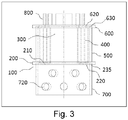
- Figure 3 shows some components of an undivided monopolar or bipolar cell for gas lifting processes (natural circulation by effect of the gas produced at the surface of the electrodes) according to one embodiment of the present invention that employs the support structure (100) already described in Figure 1 , equipped with a support plane (200) and a partition member (300) that is orthogonal thereto.
- the support plane (200) is provided with grooves (210) for housing the electrodes (400) having a shape homothetic to each other and through holes (220) intercalated to said grooves.
- the cell also comprises a side containing wall (500), which in this embodiment has a cylindrical and hollow geometry.
- the electrolytic cell further comprises an insulating containing plane (600), suitable for delimiting the upper volume of the area containing the electrodes and suitable for insulating the upper edges thereof.
- the insulating containing plane is in this embodiment provided with through holes (620) that allow the electrical connection of the electrodes to an external power supply system through the contacts (800) and of further through holes (not shown in the drawing) able to allow the passage of electrolytic solution through the plane.
- the insulating containing plane (600) is also provided with a groove (630) that meets with the edge of the side containing wall (500), so as to confine the volume of the cell in which the electrolytic reaction takes place and allow good electrolyte circulation.
- the support plane (200) is placed above a further wall (700), provided with holes (720), to allow the upward circulation of the electrolytic solution of the electrolyser.
- the electrolyser will comprise the components illustrated herein and arranged as described, and at least one further container suitable for enclosing or circulating the electrolyte.
- FIG 4 shows some components of an undivided monopolar or bipolar cell according to one embodiment of the present invention.
- the cell employs the electrodic support structure (100) schematically illustrated in panel I and comprising the support plane (200) provided with grooves for electrodes having the shape of the arc of a circle (210), the partition member (300), a cross section of which is shown.
- the latter is provided with electrode insertion and support means in the form of slits (310), of a prism member (350), shown here in cross section, of cylindrical shape and equipped with a through hole (370) that also crosses the support plane (200).
- the electrodes (400) of the electrolytic cell arranged in the grooves (210) of the support structure (100), are inserted into a central chamber comprised between the support plane (200), the side containing wall (500) and the insulating containing plane (600).
- the latter is in turn equipped with a groove (630) to house the edge of the wall (500).
- the system described herein is raised and rests on the wall (700), which defines a lower chamber that is closed by the base (900).
- the system described above is surmounted by an upper chamber delimited by the containing plane (600), the wall (750) and the cover (950).
- the electrical connection of the electrodes to an external power supply system takes place by means of the contacts (800), which pass through the surfaces (950) and (600) by means of suitable through holes (not shown in the drawing).
- the prism member (300) extends above and below the support plane (200) in all three of the chambers described above.
- the prism member (300) is provided with a through hole (370) suitable for placing in communication the intake (1000) of the electrolyte with the lower chamber directly.
- the electrolyte reaches the central chamber in which the electrolytic reaction takes place through the through holes (220) made on the support plane (200) and crosses it, reaching the upper chamber through the through holes (620) made on the containing plane (600). The solution is thus drawn toward the outside through the outlet (1100).
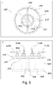
- FIG 5 panel I, shows a front view of an electrodic support structure (100) according to the invention, suitable for being employed in the divided monopolar cell illustrated in panel II.
- the electrodic support structure is equipped with a support plane (200) provided with semi-circular shaped grooves (210), to house analogous shaped electrodes, and four through holes (220) suitable for allowing the inlet and outlet of the electrolytic solution. Through holes (not shown) are made at the grooves (210), to allow the electrical connection of the electrodes to the power supply.
- the partition member (300) is equipped with holes that pass through its major surfaces (such as the partition member of Figure 2 ) and is provided with vertical slits (310) placed at each end of the grooves (210).
- Panel II shows a side view of a double coaxial cell that is monopolar and divided according to one embodiment of the present invention.
- the cell which allows the production of two different solutions, an anolyte and a catholyte having different composition and pH, integrates the electrodic support structure (100) illustrated in the panel (I).
- the intakes (1000, 1050) and the relative outlets (1100, 1150), allow circulation of the catholyte and anolyte, through the through holes (220), in the two areas of the cell delimited by the electrodes (400) corresponding thereto.
- a suitably supported membrane or diaphragm can be positioned between the electrodes. Both the anolyte and the catholyte pass through the partition member (300) through the through holes made therein.
- the electrodes are supplied with electricity through the contacts (800).
- FIG. 6 illustrates two possible embodiments of the support structure (100) according to the invention.
- Panels I and II both have a partition member (300) made so as to subdivide the support plane (200) into an even number of areas for housing of electrodes in their seats (210) that is greater than two.
- the partition member further comprises some slits (310) arranged along a direction defined by the straight line tangent at the end of the groove of the support plane corresponding thereto.
- the central prism member (350) has a square cross section and is placed close to the edge of the housing seats of lower length.
Landscapes
- Chemical & Material Sciences (AREA)
- Engineering & Computer Science (AREA)
- Chemical Kinetics & Catalysis (AREA)
- Electrochemistry (AREA)
- Organic Chemistry (AREA)
- Materials Engineering (AREA)
- Metallurgy (AREA)
- Life Sciences & Earth Sciences (AREA)
- General Chemical & Material Sciences (AREA)
- Hydrology & Water Resources (AREA)
- Environmental & Geological Engineering (AREA)
- Water Supply & Treatment (AREA)
- Sustainable Development (AREA)
- Automation & Control Theory (AREA)
- Electrolytic Production Of Non-Metals, Compounds, Apparatuses Therefor (AREA)
- Electrolytic Production Of Metals (AREA)
- Electrodes For Compound Or Non-Metal Manufacture (AREA)
Claims (9)
- Structure de support d'électrodes (100) pour cellules électrolytiques coaxiales adaptée pour loger une pluralité d'électrodes (400), comprenant :- un plan de support (200) réalisé dans un matériau isolant pourvu d'une pluralité de sièges de logement (210) adaptés pour loger ladite pluralité d'électrodes ;- un élément de séparation (300) réalisé dans un matériau isolant solidaire ou relié mécaniquement audit plan de support (200) ;ledit élément de séparation (300) étant un élément mis en forme composite et continu comprenant un élément de prisme à angle droit (350) équipé d'une base de forme circulaire, elliptique, ovale ou polygonale présentant une symétrie centrale ; ledit élément de prisme à angle droit (350) ayant ladite base orientée parallèlement audit plan de support et étant positionné au centre de la base dudit élément de séparation placé au niveau dudit plan de support et étant agencé orthogonalement audit plan de support ; ledit élément de séparation (300) étant pourvu d'une pluralité de moyens de positionnement (310) adaptés pour positionner ladite pluralité d'électrodes, au moins un siège de logement (210) de ladite pluralité de sièges de logement étant agencé le long d'une partie de bord de ladite base dudit élément de prisme à angle droit.
- Structure de support d'électrodes selon la revendication 1, dans laquelle chaque siège de logement (210) comprend une rainure et ledit élément de séparation (300) a au moins un moyen de positionnement (310) agencé au niveau de l'extrémité, au moins au nombre de une, de chacune desdites rainures.
- Structure de support d'électrodes selon la revendication 2, dans laquelle lesdits moyens de positionnement (310) sont des fentes orthogonales audit plan de support, chaque fente étant agencée à une extrémité d'un desdits sièges de logement (210), chaque fente pénétrant dans ledit élément de séparation (300) dans la direction de la tangente dudit siège de logement au niveau de ladite extrémité de celui-ci.
- Structure de support d'électrodes selon l'une des revendications 1 à 3, dans laquelle ladite pluralité de sièges de logement comprend une pluralité de rainures, ayant une forme homothétique les unes par rapport aux autres.
- Structure de support d'électrodes selon l'une des revendications 1 à 4, dans laquelle ledit élément de séparation (300) a au moins un trou traversant (320) à travers deux surfaces opposées de celui-ci, ledit trou traversant, au moins au nombre de un, étant adapté au passage de la solution électrolytique.
- Structure de support d'électrodes selon l'une des revendications 1 à 5, dans laquelle au moins deux sièges de logement de ladite pluralité de sièges de logement sont intercalés par une ou plusieurs ouvertures (220) qui passent à travers ledit plan de support.
- Structure de support d'électrodes selon l'une des revendications 1 à 6, dans laquelle ledit plan de support (200) est pourvu d'au moins deux paires de sièges de logement (210), comprenant :- une paire externe de sièges de logement, ladite paire externe étant divisée en un premier siège de logement externe et un second siège de logement externe, lesdits premier et second sièges de logement externes étant adaptés pour loger une paire d'électrodes de mêmes dimensions, lesdits premier et second sièges de logement externes étant séparés l'un de l'autre par ledit élément de séparation (300) ;- une paire interne de sièges de logement, ladite paire interne étant divisée en un premier siège de logement interne et un second siège de logement interne, lesdits premier et second sièges de logement internes étant adaptés pour loger une paire d'électrodes de mêmes dimensions, lesdits premier et second sièges de logement internes étant séparés l'un de l'autre par ledit élément de séparation (300).
- Cellule électrolytique coaxiale, comprenant :- la structure de support d'électrodes (100) selon l'une des revendications 1 à 6;- un plan de confinement isolant (600) agencé parallèlement audit plan de support (200) ;- au moins une paroi latérale de confinement (500) solidaire du ou connectée audit plan de support (200) et solidaire du ou connectée audit plan de confinement isolant (600) et interposée orthogonalement par rapport à celui-ci ;- une pluralité d'électrodes (400) logées dans ladite pluralité de sièges de logement et positionnées dans ladite pluralité de moyens de positionnement de ladite structure de support d'électrodes ;ledit élément de séparation et ladite pluralité d'électrodes étant contenus au sein du système comprenant ladite structure de support d'électrodes, ledit plan de confinement et ladite paroi latérale de confinement, au moins au nombre de une.
- Cellule électrolytique coaxiale selon la revendication 8, dans laquelle ledit plan de confinement isolant (600) est pourvu :- d'au moins une ouverture d'entrée et d'au moins une ouverture de sortie pour faire circuler une solution électrolytique à l'intérieur du système comprenant ladite structure de support d'électrodes (100), ledit plan de confinement isolant (600) et ladite paroi latérale de confinement (500), au moins au nombre de une,- d'une pluralité d'ouvertures adaptées au passage d'une ou plusieurs connexions électriques pour fournir de l'électricité à ladite pluralité d'électrodes (400).
Applications Claiming Priority (2)
| Application Number | Priority Date | Filing Date | Title |
|---|---|---|---|
| IT102016000123656A IT201600123656A1 (it) | 2016-12-06 | 2016-12-06 | Struttura di supporto elettrodica per celle elettrolitiche coassiali |
| PCT/IB2017/057644 WO2018104855A1 (fr) | 2016-12-06 | 2017-12-05 | Structure de support d'électrodes pour cellules électrolytiques coaxiales |
Publications (2)
| Publication Number | Publication Date |
|---|---|
| EP3551782A1 EP3551782A1 (fr) | 2019-10-16 |
| EP3551782B1 true EP3551782B1 (fr) | 2020-09-30 |
Family
ID=58545063
Family Applications (1)
| Application Number | Title | Priority Date | Filing Date |
|---|---|---|---|
| EP17826281.2A Active EP3551782B1 (fr) | 2016-12-06 | 2017-12-05 | Structure de support d'électrodes pour cellules électrolytiques coaxiales |
Country Status (15)
| Country | Link |
|---|---|
| US (1) | US10988850B2 (fr) |
| EP (1) | EP3551782B1 (fr) |
| JP (1) | JP6810273B2 (fr) |
| KR (1) | KR102025064B1 (fr) |
| CN (1) | CN110036141B (fr) |
| AU (1) | AU2017372932A1 (fr) |
| BR (1) | BR112019010987A2 (fr) |
| CL (1) | CL2019001436A1 (fr) |
| EA (1) | EA201991320A1 (fr) |
| ES (1) | ES2836112T3 (fr) |
| IL (1) | IL266900B (fr) |
| IT (1) | IT201600123656A1 (fr) |
| MX (1) | MX2019006254A (fr) |
| WO (1) | WO2018104855A1 (fr) |
| ZA (1) | ZA201902836B (fr) |
Families Citing this family (2)
| Publication number | Priority date | Publication date | Assignee | Title |
|---|---|---|---|---|
| CN112811526A (zh) * | 2020-12-31 | 2021-05-18 | 周廷云 | 酸性氧化电位水连续生成机及其生成方法 |
| CN118329124B (zh) * | 2024-06-07 | 2024-08-13 | 中国科学院海洋研究所 | 一种温度和电导率同测传感器制备方法及传感器 |
Family Cites Families (14)
| Publication number | Priority date | Publication date | Assignee | Title |
|---|---|---|---|---|
| GB1519679A (en) * | 1976-12-09 | 1978-08-02 | Spirig Ernst | Water decomposing apparatus |
| US4822472A (en) * | 1980-02-19 | 1989-04-18 | August K. Reis | Electrolytic cell for a disinfection device |
| US5348683A (en) * | 1990-02-06 | 1994-09-20 | Olin Corporation | Chloric acid - alkali metal chlorate mixtures and chlorine dioxide generation |
| DE4120679C2 (de) * | 1991-06-22 | 1995-11-09 | Grimma Masch Anlagen Gmbh | Elektrolyseverfahren und Elektrolysezelle für gasentwickelnde oder gasverbrauchende elektrolytische Prozesse |
| US5753098A (en) * | 1996-04-22 | 1998-05-19 | Excel Technologies International Corp. | Cylindrical electrolyzer assembly and method |
| WO2004097072A1 (fr) * | 2003-04-30 | 2004-11-11 | Hydrox Holdings Limited | Procede et appareil pour produire un fluide combustible |
| WO2005077058A2 (fr) * | 2004-02-05 | 2005-08-25 | Hydrogen Innnovations, Llc | Systeme d'alimentation en carburant pour moteur a combustion interne |
| EP2321228A1 (fr) * | 2008-06-19 | 2011-05-18 | Tennant Company | Cellule électrolytique tubulaire comprenant des électrodes concentriques, et procédé associé |
| KR101061227B1 (ko) * | 2008-11-27 | 2011-08-31 | 최장수 | 수중 플라즈마 방전을 이용한 수산기 라디칼 수와 수소산소가스 발생장치 및 이를 이용한 시스템 |
| GB0921953D0 (en) * | 2009-12-16 | 2010-02-03 | Enpar Technologies Inc | Flow-through electro static water filter |
| JP5902189B2 (ja) * | 2010-11-18 | 2016-04-13 | メタリシス リミテッド | 電解装置 |
| ITMI20121048A1 (it) | 2012-06-18 | 2013-12-19 | Industrie De Nora Spa | Cella elettrolitica dotata di coppie concentriche di elettrodi |
| ITMI20132015A1 (it) * | 2013-12-03 | 2015-06-04 | Industrie De Nora Spa | Cella elettrolitica dotata di coppie concentriche di elettrodi |
| CN105277184B (zh) * | 2015-11-09 | 2018-01-02 | 中国人民解放军国防科学技术大学 | 多层式圆柱壳体振动陀螺谐振子 |
-
2016
- 2016-12-06 IT IT102016000123656A patent/IT201600123656A1/it unknown
-
2017
- 2017-12-05 JP JP2019538216A patent/JP6810273B2/ja not_active Expired - Fee Related
- 2017-12-05 MX MX2019006254A patent/MX2019006254A/es unknown
- 2017-12-05 AU AU2017372932A patent/AU2017372932A1/en not_active Abandoned
- 2017-12-05 ES ES17826281T patent/ES2836112T3/es active Active
- 2017-12-05 EA EA201991320A patent/EA201991320A1/ru unknown
- 2017-12-05 KR KR1020197015009A patent/KR102025064B1/ko not_active Expired - Fee Related
- 2017-12-05 BR BR112019010987-0A patent/BR112019010987A2/pt not_active Application Discontinuation
- 2017-12-05 EP EP17826281.2A patent/EP3551782B1/fr active Active
- 2017-12-05 CN CN201780074965.7A patent/CN110036141B/zh not_active Expired - Fee Related
- 2017-12-05 WO PCT/IB2017/057644 patent/WO2018104855A1/fr not_active Ceased
- 2017-12-05 US US16/344,849 patent/US10988850B2/en not_active Expired - Fee Related
-
2019
- 2019-05-06 ZA ZA2019/02836A patent/ZA201902836B/en unknown
- 2019-05-27 IL IL266900A patent/IL266900B/en active IP Right Grant
- 2019-05-28 CL CL2019001436A patent/CL2019001436A1/es unknown
Non-Patent Citations (1)
| Title |
|---|
| None * |
Also Published As
| Publication number | Publication date |
|---|---|
| EP3551782A1 (fr) | 2019-10-16 |
| ZA201902836B (en) | 2020-10-28 |
| KR20190064659A (ko) | 2019-06-10 |
| CL2019001436A1 (es) | 2019-10-11 |
| IL266900B (en) | 2020-01-30 |
| IT201600123656A1 (it) | 2018-06-06 |
| WO2018104855A1 (fr) | 2018-06-14 |
| JP6810273B2 (ja) | 2021-01-06 |
| AU2017372932A1 (en) | 2019-05-23 |
| CN110036141B (zh) | 2020-03-24 |
| US10988850B2 (en) | 2021-04-27 |
| US20200063278A1 (en) | 2020-02-27 |
| KR102025064B1 (ko) | 2019-09-25 |
| IL266900A (en) | 2019-06-30 |
| CN110036141A (zh) | 2019-07-19 |
| MX2019006254A (es) | 2019-08-01 |
| EA201991320A1 (ru) | 2019-11-29 |
| JP2020501025A (ja) | 2020-01-16 |
| BR112019010987A2 (pt) | 2019-10-15 |
| ES2836112T3 (es) | 2021-06-24 |
Similar Documents
| Publication | Publication Date | Title |
|---|---|---|
| US4033848A (en) | Wafer electrode for an electrolytic cell | |
| US3984303A (en) | Membrane electrolytic cell with concentric electrodes | |
| US4137144A (en) | Hollow bipolar electrolytic cell anode-cathode connecting device | |
| FI79145B (fi) | Bipolaer elektrolysanordning med gasdiffusionskatod. | |
| EP3551782B1 (fr) | Structure de support d'électrodes pour cellules électrolytiques coaxiales | |
| CA2328150C (fr) | Appareil d'electrolyse pour produire des gaz halogene | |
| US7018516B2 (en) | Bipolar multi-purpose electrolytic cell for high current loads | |
| SU1662353A3 (ru) | Электролизер фильтрпрессного типа дл получени гидроксида натри | |
| KR200285556Y1 (ko) | 전해조 | |
| KR102705353B1 (ko) | 전해조 | |
| EP3085814B1 (fr) | Bain électrolytique à membrane ionique | |
| CN219363832U (zh) | 铜箔电解槽 | |
| US20120012468A1 (en) | Method and apparatus for producing and separating combustible gasses | |
| JP2020501025A5 (fr) | ||
| KR20240132263A (ko) | 용접된 4층 모듈들의 스택을 갖는 전해조 | |
| CN116200761A (zh) | 电解槽 | |
| HK40006220A (en) | Electrodic support structure for coaxial electrolytic cells | |
| HK40006220B (en) | Electrodic support structure for coaxial electrolytic cells | |
| KR100424665B1 (ko) | 가변형 전해조에 의한 대용량 산소, 수소 혼성 가스 발생장치 | |
| JPS6119789A (ja) | 複極電極 | |
| US3562138A (en) | Structural element for use in an electrolytic cell | |
| US3864237A (en) | Bipolar diaphragmless electrolytic cells | |
| CN114438517B (zh) | 电解装置及复极框结构 | |
| EP4538426A1 (fr) | Distributeur de flux conçu pour distribuer de manière homogène des réactifs dans une cellule électrolytique, cadre de cellule le comprenant et électrolyseur comprenant le cadre de cellule | |
| SU710628A1 (ru) | Электролизер |
Legal Events
| Date | Code | Title | Description |
|---|---|---|---|
| STAA | Information on the status of an ep patent application or granted ep patent |
Free format text: STATUS: UNKNOWN |
|
| STAA | Information on the status of an ep patent application or granted ep patent |
Free format text: STATUS: THE INTERNATIONAL PUBLICATION HAS BEEN MADE |
|
| PUAI | Public reference made under article 153(3) epc to a published international application that has entered the european phase |
Free format text: ORIGINAL CODE: 0009012 |
|
| STAA | Information on the status of an ep patent application or granted ep patent |
Free format text: STATUS: REQUEST FOR EXAMINATION WAS MADE |
|
| 17P | Request for examination filed |
Effective date: 20190516 |
|
| AK | Designated contracting states |
Kind code of ref document: A1 Designated state(s): AL AT BE BG CH CY CZ DE DK EE ES FI FR GB GR HR HU IE IS IT LI LT LU LV MC MK MT NL NO PL PT RO RS SE SI SK SM TR |
|
| AX | Request for extension of the european patent |
Extension state: BA ME |
|
| DAV | Request for validation of the european patent (deleted) | ||
| DAX | Request for extension of the european patent (deleted) | ||
| GRAP | Despatch of communication of intention to grant a patent |
Free format text: ORIGINAL CODE: EPIDOSNIGR1 |
|
| STAA | Information on the status of an ep patent application or granted ep patent |
Free format text: STATUS: GRANT OF PATENT IS INTENDED |
|
| INTG | Intention to grant announced |
Effective date: 20200608 |
|
| GRAS | Grant fee paid |
Free format text: ORIGINAL CODE: EPIDOSNIGR3 |
|
| GRAA | (expected) grant |
Free format text: ORIGINAL CODE: 0009210 |
|
| STAA | Information on the status of an ep patent application or granted ep patent |
Free format text: STATUS: THE PATENT HAS BEEN GRANTED |
|
| AK | Designated contracting states |
Kind code of ref document: B1 Designated state(s): AL AT BE BG CH CY CZ DE DK EE ES FI FR GB GR HR HU IE IS IT LI LT LU LV MC MK MT NL NO PL PT RO RS SE SI SK SM TR |
|
| REG | Reference to a national code |
Ref country code: GB Ref legal event code: FG4D Ref country code: CH Ref legal event code: EP |
|
| REG | Reference to a national code |
Ref country code: AT Ref legal event code: REF Ref document number: 1318880 Country of ref document: AT Kind code of ref document: T Effective date: 20201015 |
|
| REG | Reference to a national code |
Ref country code: DE Ref legal event code: R096 Ref document number: 602017024762 Country of ref document: DE |
|
| REG | Reference to a national code |
Ref country code: IE Ref legal event code: FG4D |
|
| REG | Reference to a national code |
Ref country code: CH Ref legal event code: NV Representative=s name: FIAMMENGHI-FIAMMENGHI, CH |
|
| REG | Reference to a national code |
Ref country code: DE Ref legal event code: R079 Ref document number: 602017024762 Country of ref document: DE Free format text: PREVIOUS MAIN CLASS: C25B0009060000 Ipc: C25B0009170000 |
|
| REG | Reference to a national code |
Ref country code: NL Ref legal event code: FP |
|
| PG25 | Lapsed in a contracting state [announced via postgrant information from national office to epo] |
Ref country code: GR Free format text: LAPSE BECAUSE OF FAILURE TO SUBMIT A TRANSLATION OF THE DESCRIPTION OR TO PAY THE FEE WITHIN THE PRESCRIBED TIME-LIMIT Effective date: 20201231 Ref country code: NO Free format text: LAPSE BECAUSE OF FAILURE TO SUBMIT A TRANSLATION OF THE DESCRIPTION OR TO PAY THE FEE WITHIN THE PRESCRIBED TIME-LIMIT Effective date: 20201230 Ref country code: FI Free format text: LAPSE BECAUSE OF FAILURE TO SUBMIT A TRANSLATION OF THE DESCRIPTION OR TO PAY THE FEE WITHIN THE PRESCRIBED TIME-LIMIT Effective date: 20200930 Ref country code: SE Free format text: LAPSE BECAUSE OF FAILURE TO SUBMIT A TRANSLATION OF THE DESCRIPTION OR TO PAY THE FEE WITHIN THE PRESCRIBED TIME-LIMIT Effective date: 20200930 Ref country code: HR Free format text: LAPSE BECAUSE OF FAILURE TO SUBMIT A TRANSLATION OF THE DESCRIPTION OR TO PAY THE FEE WITHIN THE PRESCRIBED TIME-LIMIT Effective date: 20200930 Ref country code: BG Free format text: LAPSE BECAUSE OF FAILURE TO SUBMIT A TRANSLATION OF THE DESCRIPTION OR TO PAY THE FEE WITHIN THE PRESCRIBED TIME-LIMIT Effective date: 20201230 |
|
| PGFP | Annual fee paid to national office [announced via postgrant information from national office to epo] |
Ref country code: DE Payment date: 20201211 Year of fee payment: 4 Ref country code: IT Payment date: 20201231 Year of fee payment: 4 Ref country code: FR Payment date: 20201223 Year of fee payment: 4 Ref country code: CH Payment date: 20201221 Year of fee payment: 4 |
|
| REG | Reference to a national code |
Ref country code: AT Ref legal event code: MK05 Ref document number: 1318880 Country of ref document: AT Kind code of ref document: T Effective date: 20200930 |
|
| PG25 | Lapsed in a contracting state [announced via postgrant information from national office to epo] |
Ref country code: LV Free format text: LAPSE BECAUSE OF FAILURE TO SUBMIT A TRANSLATION OF THE DESCRIPTION OR TO PAY THE FEE WITHIN THE PRESCRIBED TIME-LIMIT Effective date: 20200930 Ref country code: RS Free format text: LAPSE BECAUSE OF FAILURE TO SUBMIT A TRANSLATION OF THE DESCRIPTION OR TO PAY THE FEE WITHIN THE PRESCRIBED TIME-LIMIT Effective date: 20200930 |
|
| PGFP | Annual fee paid to national office [announced via postgrant information from national office to epo] |
Ref country code: NL Payment date: 20201221 Year of fee payment: 4 |
|
| REG | Reference to a national code |
Ref country code: LT Ref legal event code: MG4D |
|
| PG25 | Lapsed in a contracting state [announced via postgrant information from national office to epo] |
Ref country code: EE Free format text: LAPSE BECAUSE OF FAILURE TO SUBMIT A TRANSLATION OF THE DESCRIPTION OR TO PAY THE FEE WITHIN THE PRESCRIBED TIME-LIMIT Effective date: 20200930 Ref country code: RO Free format text: LAPSE BECAUSE OF FAILURE TO SUBMIT A TRANSLATION OF THE DESCRIPTION OR TO PAY THE FEE WITHIN THE PRESCRIBED TIME-LIMIT Effective date: 20200930 Ref country code: PT Free format text: LAPSE BECAUSE OF FAILURE TO SUBMIT A TRANSLATION OF THE DESCRIPTION OR TO PAY THE FEE WITHIN THE PRESCRIBED TIME-LIMIT Effective date: 20210201 Ref country code: CZ Free format text: LAPSE BECAUSE OF FAILURE TO SUBMIT A TRANSLATION OF THE DESCRIPTION OR TO PAY THE FEE WITHIN THE PRESCRIBED TIME-LIMIT Effective date: 20200930 Ref country code: LT Free format text: LAPSE BECAUSE OF FAILURE TO SUBMIT A TRANSLATION OF THE DESCRIPTION OR TO PAY THE FEE WITHIN THE PRESCRIBED TIME-LIMIT Effective date: 20200930 Ref country code: SM Free format text: LAPSE BECAUSE OF FAILURE TO SUBMIT A TRANSLATION OF THE DESCRIPTION OR TO PAY THE FEE WITHIN THE PRESCRIBED TIME-LIMIT Effective date: 20200930 |
|
| PG25 | Lapsed in a contracting state [announced via postgrant information from national office to epo] |
Ref country code: PL Free format text: LAPSE BECAUSE OF FAILURE TO SUBMIT A TRANSLATION OF THE DESCRIPTION OR TO PAY THE FEE WITHIN THE PRESCRIBED TIME-LIMIT Effective date: 20200930 Ref country code: IS Free format text: LAPSE BECAUSE OF FAILURE TO SUBMIT A TRANSLATION OF THE DESCRIPTION OR TO PAY THE FEE WITHIN THE PRESCRIBED TIME-LIMIT Effective date: 20210130 Ref country code: AT Free format text: LAPSE BECAUSE OF FAILURE TO SUBMIT A TRANSLATION OF THE DESCRIPTION OR TO PAY THE FEE WITHIN THE PRESCRIBED TIME-LIMIT Effective date: 20200930 Ref country code: AL Free format text: LAPSE BECAUSE OF FAILURE TO SUBMIT A TRANSLATION OF THE DESCRIPTION OR TO PAY THE FEE WITHIN THE PRESCRIBED TIME-LIMIT Effective date: 20200930 |
|
| PGFP | Annual fee paid to national office [announced via postgrant information from national office to epo] |
Ref country code: ES Payment date: 20210223 Year of fee payment: 4 |
|
| REG | Reference to a national code |
Ref country code: ES Ref legal event code: FG2A Ref document number: 2836112 Country of ref document: ES Kind code of ref document: T3 Effective date: 20210624 |
|
| PG25 | Lapsed in a contracting state [announced via postgrant information from national office to epo] |
Ref country code: SK Free format text: LAPSE BECAUSE OF FAILURE TO SUBMIT A TRANSLATION OF THE DESCRIPTION OR TO PAY THE FEE WITHIN THE PRESCRIBED TIME-LIMIT Effective date: 20200930 |
|
| REG | Reference to a national code |
Ref country code: DE Ref legal event code: R097 Ref document number: 602017024762 Country of ref document: DE |
|
| PLBE | No opposition filed within time limit |
Free format text: ORIGINAL CODE: 0009261 |
|
| STAA | Information on the status of an ep patent application or granted ep patent |
Free format text: STATUS: NO OPPOSITION FILED WITHIN TIME LIMIT |
|
| PG25 | Lapsed in a contracting state [announced via postgrant information from national office to epo] |
Ref country code: DK Free format text: LAPSE BECAUSE OF FAILURE TO SUBMIT A TRANSLATION OF THE DESCRIPTION OR TO PAY THE FEE WITHIN THE PRESCRIBED TIME-LIMIT Effective date: 20200930 Ref country code: MC Free format text: LAPSE BECAUSE OF FAILURE TO SUBMIT A TRANSLATION OF THE DESCRIPTION OR TO PAY THE FEE WITHIN THE PRESCRIBED TIME-LIMIT Effective date: 20200930 |
|
| REG | Reference to a national code |
Ref country code: BE Ref legal event code: MM Effective date: 20201231 |
|
| 26N | No opposition filed |
Effective date: 20210701 |
|
| PG25 | Lapsed in a contracting state [announced via postgrant information from national office to epo] |
Ref country code: IE Free format text: LAPSE BECAUSE OF NON-PAYMENT OF DUE FEES Effective date: 20201205 Ref country code: LU Free format text: LAPSE BECAUSE OF NON-PAYMENT OF DUE FEES Effective date: 20201205 |
|
| PG25 | Lapsed in a contracting state [announced via postgrant information from national office to epo] |
Ref country code: SI Free format text: LAPSE BECAUSE OF FAILURE TO SUBMIT A TRANSLATION OF THE DESCRIPTION OR TO PAY THE FEE WITHIN THE PRESCRIBED TIME-LIMIT Effective date: 20200930 |
|
| PG25 | Lapsed in a contracting state [announced via postgrant information from national office to epo] |
Ref country code: IS Free format text: LAPSE BECAUSE OF FAILURE TO SUBMIT A TRANSLATION OF THE DESCRIPTION OR TO PAY THE FEE WITHIN THE PRESCRIBED TIME-LIMIT Effective date: 20210130 Ref country code: TR Free format text: LAPSE BECAUSE OF FAILURE TO SUBMIT A TRANSLATION OF THE DESCRIPTION OR TO PAY THE FEE WITHIN THE PRESCRIBED TIME-LIMIT Effective date: 20200930 Ref country code: MT Free format text: LAPSE BECAUSE OF FAILURE TO SUBMIT A TRANSLATION OF THE DESCRIPTION OR TO PAY THE FEE WITHIN THE PRESCRIBED TIME-LIMIT Effective date: 20200930 Ref country code: CY Free format text: LAPSE BECAUSE OF FAILURE TO SUBMIT A TRANSLATION OF THE DESCRIPTION OR TO PAY THE FEE WITHIN THE PRESCRIBED TIME-LIMIT Effective date: 20200930 |
|
| PG25 | Lapsed in a contracting state [announced via postgrant information from national office to epo] |
Ref country code: MK Free format text: LAPSE BECAUSE OF FAILURE TO SUBMIT A TRANSLATION OF THE DESCRIPTION OR TO PAY THE FEE WITHIN THE PRESCRIBED TIME-LIMIT Effective date: 20200930 |
|
| REG | Reference to a national code |
Ref country code: DE Ref legal event code: R119 Ref document number: 602017024762 Country of ref document: DE |
|
| PG25 | Lapsed in a contracting state [announced via postgrant information from national office to epo] |
Ref country code: BE Free format text: LAPSE BECAUSE OF NON-PAYMENT OF DUE FEES Effective date: 20201231 |
|
| REG | Reference to a national code |
Ref country code: CH Ref legal event code: PL |
|
| REG | Reference to a national code |
Ref country code: NL Ref legal event code: MM Effective date: 20220101 |
|
| GBPC | Gb: european patent ceased through non-payment of renewal fee |
Effective date: 20211205 |
|
| PG25 | Lapsed in a contracting state [announced via postgrant information from national office to epo] |
Ref country code: NL Free format text: LAPSE BECAUSE OF NON-PAYMENT OF DUE FEES Effective date: 20220101 |
|
| PG25 | Lapsed in a contracting state [announced via postgrant information from national office to epo] |
Ref country code: GB Free format text: LAPSE BECAUSE OF NON-PAYMENT OF DUE FEES Effective date: 20211205 Ref country code: DE Free format text: LAPSE BECAUSE OF NON-PAYMENT OF DUE FEES Effective date: 20220701 |
|
| PG25 | Lapsed in a contracting state [announced via postgrant information from national office to epo] |
Ref country code: FR Free format text: LAPSE BECAUSE OF NON-PAYMENT OF DUE FEES Effective date: 20211231 |
|
| PG25 | Lapsed in a contracting state [announced via postgrant information from national office to epo] |
Ref country code: LI Free format text: LAPSE BECAUSE OF NON-PAYMENT OF DUE FEES Effective date: 20211231 Ref country code: CH Free format text: LAPSE BECAUSE OF NON-PAYMENT OF DUE FEES Effective date: 20211231 |
|
| PG25 | Lapsed in a contracting state [announced via postgrant information from national office to epo] |
Ref country code: IT Free format text: LAPSE BECAUSE OF NON-PAYMENT OF DUE FEES Effective date: 20211205 |
|
| REG | Reference to a national code |
Ref country code: ES Ref legal event code: FD2A Effective date: 20230203 |
|
| PG25 | Lapsed in a contracting state [announced via postgrant information from national office to epo] |
Ref country code: ES Free format text: LAPSE BECAUSE OF NON-PAYMENT OF DUE FEES Effective date: 20211206 |