EP3551571B1 - Wasserspender zur ausgabe von kohlensäurehaltigem wasser und verfahren - Google Patents
Wasserspender zur ausgabe von kohlensäurehaltigem wasser und verfahren Download PDFInfo
- Publication number
- EP3551571B1 EP3551571B1 EP17817291.2A EP17817291A EP3551571B1 EP 3551571 B1 EP3551571 B1 EP 3551571B1 EP 17817291 A EP17817291 A EP 17817291A EP 3551571 B1 EP3551571 B1 EP 3551571B1
- Authority
- EP
- European Patent Office
- Prior art keywords
- water
- carbonized
- conditioning chamber
- carbonized water
- volume
- Prior art date
- Legal status (The legal status is an assumption and is not a legal conclusion. Google has not performed a legal analysis and makes no representation as to the accuracy of the status listed.)
- Active
Links
Images

Classifications
-
- B—PERFORMING OPERATIONS; TRANSPORTING
- B01—PHYSICAL OR CHEMICAL PROCESSES OR APPARATUS IN GENERAL
- B01F—MIXING, e.g. DISSOLVING, EMULSIFYING OR DISPERSING
- B01F23/00—Mixing according to the phases to be mixed, e.g. dispersing or emulsifying
- B01F23/20—Mixing gases with liquids
- B01F23/23—Mixing gases with liquids by introducing gases into liquid media, e.g. for producing aerated liquids
- B01F23/236—Mixing gases with liquids by introducing gases into liquid media, e.g. for producing aerated liquids specially adapted for aerating or carbonating beverages
- B01F23/2363—Mixing systems, i.e. flow charts or diagrams; Arrangements, e.g. comprising controlling means
-
- B—PERFORMING OPERATIONS; TRANSPORTING
- B01—PHYSICAL OR CHEMICAL PROCESSES OR APPARATUS IN GENERAL
- B01F—MIXING, e.g. DISSOLVING, EMULSIFYING OR DISPERSING
- B01F23/00—Mixing according to the phases to be mixed, e.g. dispersing or emulsifying
- B01F23/20—Mixing gases with liquids
- B01F23/23—Mixing gases with liquids by introducing gases into liquid media, e.g. for producing aerated liquids
- B01F23/236—Mixing gases with liquids by introducing gases into liquid media, e.g. for producing aerated liquids specially adapted for aerating or carbonating beverages
- B01F23/2362—Mixing gases with liquids by introducing gases into liquid media, e.g. for producing aerated liquids specially adapted for aerating or carbonating beverages for aerating or carbonating within receptacles or tanks, e.g. distribution machines
-
- B—PERFORMING OPERATIONS; TRANSPORTING
- B01—PHYSICAL OR CHEMICAL PROCESSES OR APPARATUS IN GENERAL
- B01F—MIXING, e.g. DISSOLVING, EMULSIFYING OR DISPERSING
- B01F23/00—Mixing according to the phases to be mixed, e.g. dispersing or emulsifying
- B01F23/20—Mixing gases with liquids
- B01F23/23—Mixing gases with liquids by introducing gases into liquid media, e.g. for producing aerated liquids
- B01F23/236—Mixing gases with liquids by introducing gases into liquid media, e.g. for producing aerated liquids specially adapted for aerating or carbonating beverages
- B01F23/2364—Mixing gases with liquids by introducing gases into liquid media, e.g. for producing aerated liquids specially adapted for aerating or carbonating beverages using security elements, e.g. valves, for relieving overpressure
-
- B—PERFORMING OPERATIONS; TRANSPORTING
- B01—PHYSICAL OR CHEMICAL PROCESSES OR APPARATUS IN GENERAL
- B01F—MIXING, e.g. DISSOLVING, EMULSIFYING OR DISPERSING
- B01F23/00—Mixing according to the phases to be mixed, e.g. dispersing or emulsifying
- B01F23/20—Mixing gases with liquids
- B01F23/23—Mixing gases with liquids by introducing gases into liquid media, e.g. for producing aerated liquids
- B01F23/237—Mixing gases with liquids by introducing gases into liquid media, e.g. for producing aerated liquids characterised by the physical or chemical properties of gases or vapours introduced in the liquid media
- B01F23/2376—Mixing gases with liquids by introducing gases into liquid media, e.g. for producing aerated liquids characterised by the physical or chemical properties of gases or vapours introduced in the liquid media characterised by the gas being introduced
- B01F23/23762—Carbon dioxide
- B01F23/237621—Carbon dioxide in beverages
-
- B—PERFORMING OPERATIONS; TRANSPORTING
- B01—PHYSICAL OR CHEMICAL PROCESSES OR APPARATUS IN GENERAL
- B01F—MIXING, e.g. DISSOLVING, EMULSIFYING OR DISPERSING
- B01F25/00—Flow mixers; Mixers for falling materials, e.g. solid particles
- B01F25/20—Jet mixers, i.e. mixers using high-speed fluid streams
-
- B—PERFORMING OPERATIONS; TRANSPORTING
- B01—PHYSICAL OR CHEMICAL PROCESSES OR APPARATUS IN GENERAL
- B01F—MIXING, e.g. DISSOLVING, EMULSIFYING OR DISPERSING
- B01F25/00—Flow mixers; Mixers for falling materials, e.g. solid particles
- B01F25/30—Injector mixers
- B01F25/31—Injector mixers in conduits or tubes through which the main component flows
- B01F25/312—Injector mixers in conduits or tubes through which the main component flows with Venturi elements; Details thereof
- B01F25/3124—Injector mixers in conduits or tubes through which the main component flows with Venturi elements; Details thereof characterised by the place of introduction of the main flow
- B01F25/31243—Eductor or eductor-type venturi, i.e. the main flow being injected through the venturi with high speed in the form of a jet
-
- B—PERFORMING OPERATIONS; TRANSPORTING
- B01—PHYSICAL OR CHEMICAL PROCESSES OR APPARATUS IN GENERAL
- B01F—MIXING, e.g. DISSOLVING, EMULSIFYING OR DISPERSING
- B01F25/00—Flow mixers; Mixers for falling materials, e.g. solid particles
- B01F25/40—Static mixers
- B01F25/42—Static mixers in which the mixing is affected by moving the components jointly in changing directions, e.g. in tubes provided with baffles or obstructions
- B01F25/43—Mixing tubes, e.g. wherein the material is moved in a radial or partly reversed direction
- B01F25/431—Straight mixing tubes with baffles or obstructions that do not cause substantial pressure drop; Baffles therefor
- B01F25/4314—Straight mixing tubes with baffles or obstructions that do not cause substantial pressure drop; Baffles therefor with helical baffles
-
- B—PERFORMING OPERATIONS; TRANSPORTING
- B01—PHYSICAL OR CHEMICAL PROCESSES OR APPARATUS IN GENERAL
- B01F—MIXING, e.g. DISSOLVING, EMULSIFYING OR DISPERSING
- B01F25/00—Flow mixers; Mixers for falling materials, e.g. solid particles
- B01F25/40—Static mixers
- B01F25/42—Static mixers in which the mixing is affected by moving the components jointly in changing directions, e.g. in tubes provided with baffles or obstructions
- B01F25/43—Mixing tubes, e.g. wherein the material is moved in a radial or partly reversed direction
- B01F25/431—Straight mixing tubes with baffles or obstructions that do not cause substantial pressure drop; Baffles therefor
- B01F25/4314—Straight mixing tubes with baffles or obstructions that do not cause substantial pressure drop; Baffles therefor with helical baffles
- B01F25/43141—Straight mixing tubes with baffles or obstructions that do not cause substantial pressure drop; Baffles therefor with helical baffles composed of consecutive sections of helical formed elements
-
- B—PERFORMING OPERATIONS; TRANSPORTING
- B01—PHYSICAL OR CHEMICAL PROCESSES OR APPARATUS IN GENERAL
- B01F—MIXING, e.g. DISSOLVING, EMULSIFYING OR DISPERSING
- B01F33/00—Other mixers; Mixing plants; Combinations of mixers
- B01F33/80—Mixing plants; Combinations of mixers
- B01F33/82—Combinations of dissimilar mixers
- B01F33/821—Combinations of dissimilar mixers with consecutive receptacles
-
- B—PERFORMING OPERATIONS; TRANSPORTING
- B01—PHYSICAL OR CHEMICAL PROCESSES OR APPARATUS IN GENERAL
- B01F—MIXING, e.g. DISSOLVING, EMULSIFYING OR DISPERSING
- B01F35/00—Accessories for mixers; Auxiliary operations or auxiliary devices; Parts or details of general application
- B01F35/20—Measuring; Control or regulation
- B01F35/22—Control or regulation
- B01F35/222—Control or regulation of the operation of the driving system, e.g. torque, speed or power of motors; of the position of mixing devices or elements
-
- B—PERFORMING OPERATIONS; TRANSPORTING
- B67—OPENING, CLOSING OR CLEANING BOTTLES, JARS OR SIMILAR CONTAINERS; LIQUID HANDLING
- B67D—DISPENSING, DELIVERING OR TRANSFERRING LIQUIDS, NOT OTHERWISE PROVIDED FOR
- B67D1/00—Apparatus or devices for dispensing beverages on draught
- B67D1/0003—Apparatus or devices for dispensing beverages on draught the beverage being a single liquid
- B67D1/0004—Apparatus or devices for dispensing beverages on draught the beverage being a single liquid the beverage being stored in a container, e.g. bottle, cartridge, bag-in-box, bowl
-
- B—PERFORMING OPERATIONS; TRANSPORTING
- B67—OPENING, CLOSING OR CLEANING BOTTLES, JARS OR SIMILAR CONTAINERS; LIQUID HANDLING
- B67D—DISPENSING, DELIVERING OR TRANSFERRING LIQUIDS, NOT OTHERWISE PROVIDED FOR
- B67D1/00—Apparatus or devices for dispensing beverages on draught
- B67D1/0042—Details of specific parts of the dispensers
-
- B—PERFORMING OPERATIONS; TRANSPORTING
- B67—OPENING, CLOSING OR CLEANING BOTTLES, JARS OR SIMILAR CONTAINERS; LIQUID HANDLING
- B67D—DISPENSING, DELIVERING OR TRANSFERRING LIQUIDS, NOT OTHERWISE PROVIDED FOR
- B67D1/00—Apparatus or devices for dispensing beverages on draught
- B67D1/0042—Details of specific parts of the dispensers
- B67D1/0057—Carbonators
-
- B—PERFORMING OPERATIONS; TRANSPORTING
- B67—OPENING, CLOSING OR CLEANING BOTTLES, JARS OR SIMILAR CONTAINERS; LIQUID HANDLING
- B67D—DISPENSING, DELIVERING OR TRANSFERRING LIQUIDS, NOT OTHERWISE PROVIDED FOR
- B67D1/00—Apparatus or devices for dispensing beverages on draught
- B67D1/0042—Details of specific parts of the dispensers
- B67D1/0057—Carbonators
- B67D1/0061—Carbonators with cooling means
- B67D1/0066—Carbonators with cooling means outside the carbonator
- B67D1/0068—Cooling bath
-
- B—PERFORMING OPERATIONS; TRANSPORTING
- B67—OPENING, CLOSING OR CLEANING BOTTLES, JARS OR SIMILAR CONTAINERS; LIQUID HANDLING
- B67D—DISPENSING, DELIVERING OR TRANSFERRING LIQUIDS, NOT OTHERWISE PROVIDED FOR
- B67D1/00—Apparatus or devices for dispensing beverages on draught
- B67D1/0042—Details of specific parts of the dispensers
- B67D1/0057—Carbonators
- B67D1/0069—Details
- B67D1/007—Structure of the carbonating chamber
-
- B—PERFORMING OPERATIONS; TRANSPORTING
- B67—OPENING, CLOSING OR CLEANING BOTTLES, JARS OR SIMILAR CONTAINERS; LIQUID HANDLING
- B67D—DISPENSING, DELIVERING OR TRANSFERRING LIQUIDS, NOT OTHERWISE PROVIDED FOR
- B67D1/00—Apparatus or devices for dispensing beverages on draught
- B67D1/0042—Details of specific parts of the dispensers
- B67D1/0057—Carbonators
- B67D1/0069—Details
- B67D1/0071—Carbonating by injecting CO2 in the liquid
-
- B—PERFORMING OPERATIONS; TRANSPORTING
- B67—OPENING, CLOSING OR CLEANING BOTTLES, JARS OR SIMILAR CONTAINERS; LIQUID HANDLING
- B67D—DISPENSING, DELIVERING OR TRANSFERRING LIQUIDS, NOT OTHERWISE PROVIDED FOR
- B67D1/00—Apparatus or devices for dispensing beverages on draught
- B67D1/08—Details
-
- B—PERFORMING OPERATIONS; TRANSPORTING
- B67—OPENING, CLOSING OR CLEANING BOTTLES, JARS OR SIMILAR CONTAINERS; LIQUID HANDLING
- B67D—DISPENSING, DELIVERING OR TRANSFERRING LIQUIDS, NOT OTHERWISE PROVIDED FOR
- B67D1/00—Apparatus or devices for dispensing beverages on draught
- B67D1/08—Details
- B67D1/0801—Details of beverage containers, e.g. casks, kegs
-
- B—PERFORMING OPERATIONS; TRANSPORTING
- B01—PHYSICAL OR CHEMICAL PROCESSES OR APPARATUS IN GENERAL
- B01F—MIXING, e.g. DISSOLVING, EMULSIFYING OR DISPERSING
- B01F25/00—Flow mixers; Mixers for falling materials, e.g. solid particles
- B01F2025/91—Direction of flow or arrangement of feed and discharge openings
-
- B—PERFORMING OPERATIONS; TRANSPORTING
- B01—PHYSICAL OR CHEMICAL PROCESSES OR APPARATUS IN GENERAL
- B01F—MIXING, e.g. DISSOLVING, EMULSIFYING OR DISPERSING
- B01F25/00—Flow mixers; Mixers for falling materials, e.g. solid particles
- B01F25/20—Jet mixers, i.e. mixers using high-speed fluid streams
- B01F25/25—Mixing by jets impinging against collision plates
-
- B—PERFORMING OPERATIONS; TRANSPORTING
- B01—PHYSICAL OR CHEMICAL PROCESSES OR APPARATUS IN GENERAL
- B01F—MIXING, e.g. DISSOLVING, EMULSIFYING OR DISPERSING
- B01F33/00—Other mixers; Mixing plants; Combinations of mixers
- B01F33/80—Mixing plants; Combinations of mixers
- B01F33/834—Mixing in several steps, e.g. successive steps
-
- B—PERFORMING OPERATIONS; TRANSPORTING
- B67—OPENING, CLOSING OR CLEANING BOTTLES, JARS OR SIMILAR CONTAINERS; LIQUID HANDLING
- B67D—DISPENSING, DELIVERING OR TRANSFERRING LIQUIDS, NOT OTHERWISE PROVIDED FOR
- B67D1/00—Apparatus or devices for dispensing beverages on draught
- B67D1/0042—Details of specific parts of the dispensers
- B67D1/0057—Carbonators
- B67D1/0058—In-line carbonators
-
- B—PERFORMING OPERATIONS; TRANSPORTING
- B67—OPENING, CLOSING OR CLEANING BOTTLES, JARS OR SIMILAR CONTAINERS; LIQUID HANDLING
- B67D—DISPENSING, DELIVERING OR TRANSFERRING LIQUIDS, NOT OTHERWISE PROVIDED FOR
- B67D1/00—Apparatus or devices for dispensing beverages on draught
- B67D2001/0095—Constructional details
Definitions
- Water dispensers for dispensing carbonized water are available. Water dispensers may be stand-alone devices, or incorporated into an appliance such as a refrigerator. Most commercialized devices for carbonating water comprise a cooled and pressurized water storage reservoir, also referred to as a carbonating tank or saturator.
- the water cooling reservoir is typically configured to hold a volume of water sufficient for multiple servings, to allow for dispensing multiple servings of cooled water one after the other. Furthermore, the water cooling reservoir is pressurized with carbon dioxide (CO2), such that CO2 is added to the water. Thus, a pressurized multiple servings volume of cooled and carbonized water is held in the storage reservoir.
- CO2 carbon dioxide
- in-line carbonators are used as an alternative to pressurized cooling reservoirs.
- the CO2 is added to the water while it flows from the multiple servings cooled reservoir to the dispensing outlet.
- the cooled water does not need to be stored under pressure, which allows for simplified design of the reservoir.
- Publication US3780198 discloses a system for in-line carbonation of beverages.
- the system comprises a blender, a cooler and a filler.
- a carbon dioxide diffusion-type injector is located in the line between the blender and the filler.
- the filler is configured for filling cans on an industrial scale.
- the system is not suitable for domestic use.
- the line further comprises a stabilizing chamber. In effect, the fluid flowing through the chamber is delayed in reaching the filler a sufficient length of time to permit the carbon dioxide to dissolve in the beverage ingredients before filling.
- the carbonated beverage ingredients are then passed through a valve and a strainer to the filler.
- the head space of the stabilizing chamber and the filler are also supplied with carbon dioxide.
- Publication WO2005/003019 relates to a liquid dispensing system for a household refrigerator.
- the refrigerator encloses a pressurized gas bottle for carbon dioxide, that via a pipe and a check valve is connected to the mixing unit for mixing the gas with the water.
- the mixing unit is via a tube connected to a reaction tank that via an outlet tube is connected to a first dispensing valve.
- the reaction tank is also placed within a cooled space in the refrigerator and the pressure in the tank which is created by the low pressure pump is about 5 bar. Water and gas flow from the mixing unit to the reaction tank where the mixture is stored for some time before it is taken out from the system.
- this object is achieved by designing a carbonated water dispenser featuring a carbonized water conditioning chamber according to claim 1.
- Carbonated water dispensers of the type described herein provide improved levels of carbonation with the use of a conventional in-line carbonator.
- a carbonized water dispensing device comprises:
- the carbonized water dispensing device is provided with an in-line carbonized water conditioning chamber, i.e. a conditioning chamber downstream of the carbonator and upstream of the carbonized water dispensing outlet, for receiving a single serve volume of carbonized water mixed with unresolved CO2.
- an in-line carbonized water conditioning chamber i.e. a conditioning chamber downstream of the carbonator and upstream of the carbonized water dispensing outlet, for receiving a single serve volume of carbonized water mixed with unresolved CO2.
- the single serve volume of carbonated water is received in the conditioning chamber, is held under pressure in that conditioning chamber, which pressure is subsequently lowered to atmospheric or near atmospheric pressure, after which the single serve volume is dispensed.
- a carbonized water dispenser according to the invention compared to prior art carbonized water dispensers, provides an even flow of carbonized water, the carbonized water having an increased CO2 content. It is furthermore submitted that the even, i.e. less turbulent, outflow of carbonized water also helps in maintaining the increased CO2 levels for a prolonged period of time.
- a carbonized water dispensing device is in particular useful in providing soda beverages, more in particular for combining the single serve carbonized water volume with a syrup, since these types of drinks are typically associated with high CO2 content, i.e. compared to the CO2 content of carbonized water dispensed by known carbonized water dispensers.
- the invention is advantageously used in an in-line carbonization device for dispensing predetermined single serve volumes of carbonized water.
- the water is carbonized using an in-line carbonator and an in-line flow compensator, such that with each serving, only the volume of water required for a single serve, i.e. a metered single serve volume, is carbonized while being dispensed.
- a dispenser according to the invention is configured to provide a consumer with a predetermined volume of carbonized water.
- the invention is in particular suited for use in carbonized water dispenser in the office environment or at home, to provide a consumer with the beverage of his or her choice.
- the predetermined volume can be received in a beverage container, e.g. a glass or cup.
- the dispenser is configured for also allowing a consumer to fill a bottle with carbonized water.
- a single serve may comprise a volume of 100 ml for a small cup up to 1,1 litre for large cups.
- a dispenser can be configured for providing a predetermined volume, for example a single serve volume of 250 ml, or with a range of predetermined volumes, for example a range comprising a small volume of 200 ml up to a large volume of 1,2 litre.
- a dispenser can be configured to fill a bottle, in which case the predetermined volume can be in the range of 0,250 litre, 0,5 litre and 1 litre.
- the dispenser is configured to allow a consumer to specify the predetermined volume, for example by entering the desired volume via a user interface when providing the dispensing order.
- the conditioning chamber is dimensioned to receive a charge of carbonized water sufficient to allow a user to fill at a beverage container, e.g. a cup or glass, of average size.
- the conditioning chamber may typically hold between 0,2 liter and 1,5 liter of carbonized water, preferably between 0,2 and 0,8 liter, most preferably about 0,25 liter of water.
- the dispenser is configured to provide 0,225 - 0,230 liter beverages with a high CO2 content.
- the volume of the carbonized water conditioning chamber is about 0,250 litre and the dispenser is configured to retain a beverage volume of about 0,225 - 0,230 of carbonized water in that conditioning chamber, providing a head space of about 0,025 litre.
- the mixture of the single serve volume of carbonized water and the unresolved CO2 flows into the carbonized conditioning chamber, which chamber is located downstream of the flow compensator and preferably directly downstream of an in-line flow compensator located in the water line downstream of the in-line carbonator and upstream of the conditioning chamber.
- the carbonized water conditioning chamber is dimensioned such that it can hold a single serve of carbonized water with a headspace for holding the unresolved CO2.
- the conditioning chamber is furthermore dimensioned such that, during the inflow of the mixture of the single serve volume of carbonized water and the unresolved CO2 into the chamber, a pressure increase, preferably a pressure increase of up to 1,25 - 4 bar or more, is achieved in the conditioning chamber.
- the carbonized water conditioning chamber is dimensioned such that when it holds a single serve volume of carbonized water, the headspace has a volume in the range of 5% - 50% of the single serve volume of carbonized water.
- the carbonized water conditioning chamber is an adaptable chamber, i.e. has a volume that can be adapted, for example has a moveable wall that allows for adapting the volume of the chamber.
- an adaptable carbonized water conditioning chamber allows for the volume of the carbonized water conditioning chamber to be adapted in dependency of the volume to be served, and thus allows for the dispenser to serve different single serve volumes, for example a small, a medium and a large volume serving, with a head space proportioned to said volumes, for example each with a head space volume of 20%.
- a pressure source is provided for adding a gas, preferably CO2, into the carbonized water conditioning chamber, preferably during or after the filling of the conditioning chamber with the single serve volume of carbonized water, to allow for the chamber to hold different single serve volume with a similar pressure.
- a gas preferably CO2
- the in-line carbonator is configured to provide additional CO2 when a small single serve volume is dispensed, to compensate for the small volume of carbonized water and enable a sufficient increase in pressure in the carbonized water conditioning chamber during the inflow of the mixture of the single serve volume of carbonized water and the unresolved CO2.
- the carbonized water dispensing device is configured to dispense beverages with different CO2 content, for example beverages with comparatively low CO2 content and more sparkling beverages with a high CO2 content.
- the device more in particular the outlet valve of the carbonized water conditioning chamber, can be configured to retain a single serve volume of carbonized water in the carbonized water conditioning chamber to increase the CO2 content according to the invention and thus provide beverages with a high CO2 content, and a single serve volume of carbonized water to flow directly through the conditioning chamber, i.e. without any retention, to thus provide beverages with a comparatively low CO2 content.
- the dispensing device is configured to dispense flat water, i.e. water without added CO2, this water can also flow directly through the carbonized water conditioning chamber.
- the dispenser comprises an ozone device upstream of the carbonized water conditioning chamber, which ozone device is configured to add ozone to the water flowing into the carbonized water conditioning chamber, such that the ozone can destroy any germs or similar holding in the carbonized water conditioning chamber or downstream thereof.
- the carbonized water conditioning chamber more in particular the outlet valve of the carbonized water conditioning chamber, is configured to retain the water provided with ozone for a prolonged period of time in the carbonized water conditioning chamber and thus enable the ozone to better destroy any germs or similar material in said chamber.
- the device is configured to flush the water with ozone from the carbonized water conditioning chamber and/or flush through said chamber after the water with ozone has been drained from the chamber.
- the cold water source is configured for providing for providing multiple servings, preferably at least five servings.
- the cold water source comprises a cooling reservoir having a volume of multiple servings.
- the cold water source comprises a water supply.
- This supply can consist of a simple municipal or well water feed.
- the cold water source comprises an extension of the water line, which extension passes through a chiller configured to cool the water in the water line.
- the chiller is provided in the form of a reservoir that comprises a volume of cold water, and the water line passes through said volume of cold water such that the water in the water line is cooled.
- the section of the water line comprising the in-line carbonator is located within the volume of cold water of the cold water reservoir.
- the chiller is provided in the form of a reservoir that comprises a volume of cold water and the carbonized water conditioning chamber is located at least partially within the reservoir.
- the carbonized water conditioning chamber is cooled by the cold water source, more in particular is cooled by the cooling device of the cold water reservoir.
- the reservoir is encased in a jacket of isolation material.
- the reservoir is encased in a jacket of isolation material and the carbonized water conditioning chamber is received within the same jacket of isolation material.
- the outlet valve of the carbonized water conditioning chamber and the gas outlet of the carbonized water conditioning chamber are located outside the jacket of isolation material.
- the cold water source also optionally comprises a pump to provide a consistent water pressure.
- a pump to provide a consistent water pressure.
- the pressure at a typical home or commercial water tap may vary from location to location or from time to time, providing a pump will ensure that the apparatus receives a consistent pressure no matter what the local supply pressure is.
- This same goal of providing a consistent supply pressure can be achieved by other known techniques without departing from the scope of the disclosure.
- an elevated water reservoir could use gravity and appropriately sized water conduits to provide a consistent water supply pressure.
- the incoming water pressure affects the flow and pressure through the remainder of the water line.
- a pressure of 6,5 - 8,5 bar is provided to achieve an optimal flow rate and carbonation.
- the CO2 (carbon dioxide) source can be embodied by any known way for supplying a gas.
- a commercially available CO2 canister is preferably used.
- the CO2 source would typically be connected through a regulator, which provides a controlled supply pressure to the in-line carbonator.
- the CO2 is provided at a pressure between 3 bar and 9 bar.
- the carbon dioxide pressure provided at the in-line carbonator at a pressure substantially similar to the water pressure provided at the in-line carbonator.
- the in-line carbonator, or solubilizer can be an in-line carbonator known from the prior art, for example an in-line carbonator known from US2011/0268845 .
- the carbonized water dispensing device is provided with an in-line carbonator for the solubilization of CO2 (carbon dioxide) in water, the inline carbonator comprising:
- the water carbonation system comprises an in-line flow compensator, provided in the water line downstream of the carbonator, preferably the in-line carbonator, and directly upstream of the carbonized water conditioning chamber.
- the in-line flow compensator can be an in-line flow compensator known from the prior art, for example in-line flow compensator known from US2014239519 .
- the carbonized water dispensing device is configured to mix the carbonized water with an ingredient, e.g. syrup, after the carbonized water has been held in the carbonized water conditioning chamber, preferably is incorporated in a prior art dispenser device configured for mixing carbonated water with syrup for example known from WO2016081477 or WO2016081480 .
- the dispenser comprises a seat for holding an ingredient cartridge downstream of the outlet valve of the carbonized water conditioning chamber and in the flow path of the carbonized water dispensed via said outlet valve.
- the dispenser comprises an ingredient outlet, for example a nozzle connected to an ingredient reservoir, for injecting ingredient into the flow of carbonized water and/or into the beverage container in which the single serve volume of carbonized water is dispensed.
- the user interface can be embodied by any known user command input device for providing a dispenser with instructions to serve a metered volume of water, e.g. may comprise a mechanical device such as lever or tab, or an electronic interface linked to a pump and/or valves, etc.
- the dispenser is configured to receive instructions via the internet or Wi-Fi, for example from an app on a smart phone.
- the user interface comprises a control device configured to receive a beverage dispensing order, and to subsequently actuate the carbonized water dispensing device to dispense a single serve volume of carbonized water.
- the user interface allows for the user to choose between different size beverages, each having a for example a small, a medium and a large volume serving, and/or to adjust the single serve volume, for example when the single serve carbonized water volume is mixed with a predetermined volume of ingredient, to allow for a strong or a weak mixture of single serve volume carbonized water and ingredient.
- the carbonized water conditioning chamber is furthermore provided with a gas inlet connected to a pressurized gas source, preferably a CO2 gas source, preferably the gas source providing CO2 to the in-line carbonator, for providing a pressure in the conditioning chamber, preferably a pressure in the range of 1 - 4 bar, more preferably a pressure in the range of 2 - 3 bar, to urge the single serve of carbonized water volume out of the conditioning chamber, preferably providing the single serve carbonized water volume into a beverage container with an even flow rate.
- a pressurized gas source preferably a CO2 gas source, preferably the gas source providing CO2 to the in-line carbonator
- Such an embodiment allows for a more accurate control of the pressure in the carbonized water conditioning chamber, and thus to adjust for fluctuations between servings in the unresolved CO2 mixed with the carbonized water into the carbonized water conditioning chamber, for example due to difference in water temperature and/or pressure provided by the CO2 source, etc.
- such an embodiment allows for holding different single serve volumes, e.g. a small, a medium and a large volume serving with similar pressures, prior to dispensing the single serve volume of carbonized water.
- the gas source is a CO2 gas to increase the CO2 content in the headspace.
- the CO2 source that is provided for carbonization of the water is also used for providing the additional pressure, i.e. in addition to the pressure generated by the unresolved CO2 that flows into the chamber with the carbonized water, in the conditioning chamber, preferably a pressure in the range of 1 - 4 bar.
- the gas outlet is configured to, or a further gas outlet is provided to, during the inflow of the mixture of the single serve volume of carbonized water and the unresolved CO2, enable CO2 to escape the conditioning chamber when a predetermined pressure is reached, which predetermined pressure is preferably in the range of 1,25 - 4 bar, to limit the maximum pressure in the conditioning chamber.
- Such a gas outlet can also be used in combination with a gas inlet, as mentioned above, for providing a pressure in the conditioning chamber to urge the single serve of carbonized water volume out of the conditioning chamber.
- a gas for example air or CO2
- the gas outlet serves as an overflow valve to keep the pressure in said chamber at a predetermined maximum.
- the carbonized water conditioning chamber is provided with a gas inlet configured to allow a gas, for example ambient air CO2, to flow into the carbonized water conditioning chamber while the outlet valve is open and the carbonized water flows out of the carbonized water conditioning chamber.
- a gas for example ambient air CO2
- the pressure in the carbonized water conditioning chamber is substantially similar to the ambient pressure contributes to an even outflow of carbonated water from the carbonized water conditioning chamber.
- the gas inlet is provided with a filter, for example a HEPA filter, to prevent unwanted materials from entering the carbonized water conditioning chamber with the flow of gas.
- a filter for example a HEPA filter
- the dispenser is configured to provide, i.e. the carbonized water conditioning chamber is dimensioned, different single serve volumes, for example a small, a medium and a large volume serving.
- the flow of the mixture of the small volume single serve of carbonized water and the unresolved CO2 into the carbonized water conditioning chamber provides a pressure increase sufficient to reach the predetermined pressure.
- the different single serve volumes can all be held in the carbonized water conditioning chamber without the need of adding additional pressure, for example by adding additional CO2 from a CO2 source.
- the device is configured to, after filling the conditioning chamber with the single serve carbonated water volume and prior to allowing the single serve carbonized water volume to flow out of the conditioning chamber, hold the single serve carbonated water volume for a retention period in the range of 0,5 - 8 seconds, preferably in the range of 0,5-4 seconds, for example for 2 seconds, the retention period including the pressure reduction in the conditioning chamber to atmospheric pressure or near atmospheric pressure.
- the mixture of carbonized water mixed with unresolved CO2 is allowed to settle and lower in pressure, which allows for a more even flow out of the conditioning chamber.
- a typical single serve volume of carbonized water is preferably held for a period in the range of 0,2 and 5 seconds.
- a single serve volume of carbonized water is held for a period in the range of 0,2 and 5 seconds, preferably in the range of 2 and 4 seconds, for example is held for 3 seconds, after which the pressure is lowered to an atmospheric or near atmospheric pressure, allowing the single serve volume of carbonized water to flow from the conditioning chamber without a serious pressure drop.
- the amount of CO2 dispersed into the carbonised water can be controlled by controlling the input pressure of the CO2.
- This can for example be achieved by providing the CO2 source with a controlled valve, preferably a valve controlled by the control device of the user interface.
- the valve can be used to throttle the flow of CO2.
- the valve is controlled to provide a series of short CO2 injections.
- the injected CO2 volume can be controlled by controlling the length of the injections, the time period between the injections, and the CO2 pressure of the injections. It is submitted that when the length of the injections and/or the time period between the injections is/are used to control the amount of CO2 injected in to the flow of water, simple open/closed valve can be used instead of a more complicated throttle valve.
- the device is configured to provide water without CO2.
- the CO2 source can be provided with a valve that can be closed to prevent CO2 from being injected into the water flow.
- the water carbonation system can be configured to allow water to pass the water conditioning chamber directly, i.e. without being held for a period of time, to thus promote any CO2 present in the water to escape the water by providing a more turbulent flow and/or an instant pressure drop.
- the pressure in the chamber is reduced to an atmospheric or near atmospheric level.
- This drop in pressure preferably is a controlled pressure drop, i.e. is not an instantaneous pressure drop but involves a gradual reduction of pressure over a certain time frame, preferably said time frame being in the range of 1,5 - 3 seconds, for example being 1,5 seconds.
- the time frame of the pressure drop matches with the period of time the single serve carbonized water volume is held in the conditioning chamber.
- three time periods can be distinguished with respect to the pressure inside the conditioning chamber.
- the pressure in the conditioning chamber increases due to the inflow of the single serve volume of carbonized water mixed with unresolved CO2, and optionally due to additional CO2 being injected into the conditioning chamber from the CO2 source directly, up to a certain pressure level, for example of 2,5 bar.
- the single serve is held at a substantially continuous pressure, for example at a pressure level of 2,5 bar.
- a degassing outlet can be used to keep the pressure inside the conditioning chamber at this level, and prevent an increase of the pressure due to degassing of the carbonised water held in the conditioning chamber.
- the pressure is lowered in a controlled fashion, for example over a period of 2 seconds, to atmospheric pressure or near atmospheric pressure, after which third time period the single serve volume of carbonized water is allowed to flow out of the conditioning chamber.
- the invention thus provides an in-line water carbonation system, the system comprising a chilled water line, CO2 source, an in-line carbonator, an in-line flow compensator and a carbonized water conditioning chamber.
- a single serve volume water is passed through the in-line water carbonation system to provide a single serve volume of carbonized water.
- the water carbonation system comprises an in-line carbonator for the solubilization of CO2 (carbon dioxide) in water, the in-line carbonator comprising:
- the dispensing device is configured, preferably comprises a seat, for holding an ingredient cartridge downstream of the outlet valve of the carbonized water conditioning chamber and in the flow path of the carbonized water dispensed via said outlet valve, to mix the carbonized water with an ingredient, e.g. syrup, after the carbonized water has been held in the carbonized water conditioning chamber.
- a seat for holding an ingredient cartridge downstream of the outlet valve of the carbonized water conditioning chamber and in the flow path of the carbonized water dispensed via said outlet valve, to mix the carbonized water with an ingredient, e.g. syrup, after the carbonized water has been held in the carbonized water conditioning chamber.
- the invention furthermore provides a method according to claim 15 for providing a single serve of carbonized water, preferably using a carbonized water dispensing device according to one or more of the claims 1-14, wherein the method comprises the steps:
- an apparatus for the solubilization of carbon dioxide in water more in particular an in-line carbonator, for use in a carbonized water dispenser as disclosed above, such an apparatus for the solubilization of carbon dioxide in water comprising:
- the treatment trajectories are repeated without adding more CO2 between them, but instead allow for settling of the CO2 prior to again subjecting the mixture of carbonized water mixed with unresolved CO2 to a second treatment trajectory, said treatment trajectory starting with the mixture passing through a dispersion element arranged within the conduit to create a dispersed flow. It has been found that this configuration provides an increased solubilization of carbon dioxide in water comprising.
- the rigid impact surface is provided in the form of a rib member that bridges the conduit in a direction substantially perpendicular of the longitudinal axis of the conduit, such that a part of the rib member fills a central portion of the conduit and the rib member defines two peripheral flow paths located outside of the central portion of the conduit; and wherein the tubular conduit, helical dispersion elements, and restriction portions are substantially aligned along the central longitudinal axis of the conduit, and the peripheral flow paths are offset from the central longitudinal axis of the conduit in a direction transverse to the central longitudinal axis of the conduit.
- the rib member extends across the conduit, and therefore across the flow path of the mixture of carbonized water and CO2.
- the rib member thus splits the flow path into two parallel flow paths, which are located on opposite sides of the rib member. Furthermore, the rib member extends in a direction parallel to the flow path, and thus guides the two flows of carbonized water and unresolved CO2, which provides a more laminar flow compared to prior art impact surfaces.
- the rib member thus combines a more laminar flow with an increase in pressure, and thus promotes the solubilization of CO2 in the water.
- the combination of an impact surface at the central portion of the conduit and two peripheral flow paths located outside of the central portion of the conduit combines a pressure increase in the carbonized water and CO2 mixture, and thus an increase in the CO2 content of the carbonized water.
- the rigid impact surface is provided in the form of a rib member that bridges the conduit in a direction substantially perpendicular of the longitudinal axis of the conduit, can also be provided in an in-line carbonator comprising a single conditioning trajectory.
- the restriction portion of the passive accelerators has an energy loss coefficient in the range of 0,1 to 0,44.
- the impact surface is spaced from the restriction, preferably such that the helical dispersion element extends along substantially half of the treatment trajectory and the passive accelerator extends along substantially half of the treatment trajectory.
- the conditioning trajectory comprises an expanding section, i.e. having in an increase in diameter in the flow direction, followed by a section having a continuous diameter, wherein the first and second section each extend along substantially half of the conditioning trajectory.
- the conditioning trajectory and the treatment trajectories each have a substantially similar length.
- the helical dispersion element is located downstream of the inlet and upstream of the rigid impact surface and are configured to mix the carbon dioxide and water to create an annularly-dispersed flow in the conduit.
- the passive accelerator is configured to accelerate the annular-dispersed flow of carbon dioxide and water and direct the accelerated flow of carbon dioxide and water to collide with the rigid surface, thereby creating a pressure sufficient to solubilize the carbon dioxide into the water.
- the water carbonation system comprises an in-line carbonator for the solubilization of CO2 (carbon dioxide) in water, the in-line carbonator comprising:
- Fig. 1 shows a schematic drawing of an exemplary embodiment of a carbonized water dispensing device 1 according to the invention. It is noted that the diagram shows the dispensing device partially in cross section and that components have been simplified for explanatory purpose.
- the carbonated water dispenser 1 features an in-line conditioning chamber 2.
- the carbonized water dispensing device 1 further comprises a cold water source 3, a CO2 source 4, a carbonized water dispensing outlet 5 and a water line 6 extending between the cold water source 3 and the dispensing outlet 5.
- the water line 6 comprises an in-line carbonator 7, an in-line flow compensator 8, and a user interface 9.
- the carbonized water dispensing device 1 is configured to mix the carbonized water with an ingredient, e.g. syrup, after the carbonized water has been held in the carbonized water conditioning chamber 2. Therefore, the dispensing device 1 comprises a seat 12 for holding an ingredient cartridge 13 downstream of the carbonized water conditioning chamber 2 and in the flow path of the carbonized water dispensed from the carbonized water conditioning chamber 2, to mix the carbonized water with an ingredient, e.g. syrup, after the carbonized water has been held in the carbonized water conditioning chamber.
- an ingredient e.g. syrup
- the carbonized water dispensing outlet 5 is configured for dispensing a single serve carbonized water volume into a beverage container.
- the dispensing device 1 furthermore comprises a beverage container support surface 10, which in Fig. 1 supports a beverage container in the form of a cup 11 below the carbonized water dispensing outlet for receiving a single serve carbonized water volume, in the embodiment shown mixed with an ingredient, preferably a syrup.
- the cold water source 3 is configured for providing multiple servings, preferably at least five servings.
- the cold water source 3 comprises a water supply 14 that consists of a simple municipal or well water feed.
- the cold water source 3 furthermore comprises an extension of the water line 6, which extension passes through a chiller configured to cool the water in the water line.
- the chiller is provided in the form of a reservoir 15 that comprises a volume of cold water.
- the water line 6 passes through said volume of cold water, in the embodiment shown in a spiral configuration to maximize the cooling effect, such that the water line, and thus the water in the water line is cooled.
- the cold water source 3 comprises a cooling reservoir having a volume of multiple servings.
- This reservoir could in turn be connected to a simple municipal or well water feed to keep the reservoir level constant. It is noted that the water held in the reservoir is to be carbonated after a consumer has entered a dispensing instruction into the user interface. Furthermore, from the reservoir single serve volumes are dispensed into the water line each time a consumer has entered a dispensing instruction into the user interface.
- the section of the water line 6 comprising the in-line carbonator 7 is located within the volume of cold water of the cold water reservoir 15, such that water and CO2 are cooled while being mixed.
- the cold water source also comprises a pump to provide a consistent water pressure.
- a pump to provide a consistent water pressure.
- Such a water pump is configured to pump a single serve volume of carbonized water under pressure, preferably a pressure through the water line and through the carbonized water dispensing outlet.
- the CO2 source 4 is connected to the in-line carbonator 7 and to the carbonized water conditioning chamber 2 to provide each of them with CO2.
- the CO2 source 4 can be embodied by any known way for supplying a gas.
- a commercially available CO2 canister is preferably used.
- the CO2 source would typically be connected through a regulator, which provides a controlled supply pressure to the in-line carbonator.
- the in-line carbonator 7 is configured for adding CO2 to the water provided by the cold water source 3.
- the in-line carbonator, or solubilizer can be an in-line carbonator known from the prior art.
- Fig. 1 the in-line carbonator is schematically depicted.
- the in-line carbonator is configured as the in-line carbonator shown in Fig.2 , which will be discussed in more detail further below.
- the in-line carbonator 7 is provided in the water line 6, and is connected to the CO2 source 4, for adding CO2 from the CO2 source to the water flowing through the water line from the water cooling reservoir to the carbonized water dispensing outlet.
- the in-line flow compensator 8 is provided in the water line 6, downstream of the in-line carbonator 7, for conditioning the mixture of carbonized water mixed with unresolved CO2 from the in-line flow compensator.
- the carbonized water dispenser 1 comprises the carbonized water conditioning chamber 2.
- the conditioning chamber 2 is provided downstream of the flow compensator 8 and upstream of the carbonized water dispensing outlet 5, for receiving a mixture of carbonized water mixed with unresolved CO2 from the in-line flow compensator 8.
- the carbonized water conditioning chamber 2 is provided with an outlet valve 17 and a gas outlet 18.
- the outlet valve 17 is configured for, in a closed condition, enabling the carbonized water conditioning chamber 2 to hold the single serve volume of carbonized water, and for, in an open condition, allowing the single serve volume of carbonized water to flow out of the carbonized water conditioning chamber 2 and subsequently out of the carbonized water dispensing outlet into the beverage container 11.
- the gas outlet 18 is configured for, in a closed condition, preventing unresolved CO2, which enters the conditioning chamber in combination with the single serve volume of carbonized water, from escaping the conditioning chamber.
- the unresolved CO2 is retained in the conditioning chamber while the single serve volume of carbonized water is received, which results in a pressure increase in the chamber.
- the gas outlet thus enables a pressure increase of up to 1,25 - 4 bar or more in the conditioning chamber during the inflow of the mixture of the single serve volume of carbonized water and the unresolved CO2.
- the gas outlet 18 is furthermore configured for, in an open condition, allowing unresolved CO2 to escape the conditioning chamber, and thus for the pressure in the conditioning chamber 2 to lower to atmospheric pressure or near atmospheric pressure, prior to the single serve carbonized water volume flowing out of the conditioning chamber.
- the conditioning chamber 2 is dimensioned to hold a single serve of carbonized water with a headspace. Furthermore, the carbonized water dispensing device is configured to, upon receiving a beverage dispensing order, provide the empty carbonized water conditioning chamber with a single serve volume of carbonized water, and hold the single serve of carbonized water prior to dispensing the single serve volume of carbonized water. Once the single serve volume of carbonized water is drained from the conditioning chamber, the conditioning chamber remains empty until a new beverage dispensing order is received and a new beverage is dispensed.
- the user interface 9 comprising a control device 19 configured to receive a beverage dispensing order, and subsequently actuate the carbonized water dispensing device to dispense a single serve volume of carbonized water.
- the interface 9 is provided in the form of an electronic interface, more in particular an interface comprising a push button that allows a consumer to actuate the dispenser and thus dispense a single serve volume of carbonized water.
- the user interface is connected to a valve 16, which in an open condition allows water to flow from the water supply 14 into the water line 6, to the CO2 source 4, for providing the carbonator with CO2, to the outlet valve 17 for allowing the single serve volume of carbonized water to flow out of the carbonized water conditioning chamber after it has been held, and to the gas outlet 18 to allow the pressure in the conditioning chamber to lower to atmospheric pressure or near atmospheric pressure prior to the single serve carbonized water volume flowing out of the conditioning chamber.
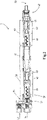
- Fig. 2 shows a detailed side view in cross section of the in-line carbonator 7.
- the in-line carbonator, or apparatus for the solubilization of carbon dioxide in water comprises a tubular conduit 51 disposed about a longitudinal axis, extending from an input end 52 to and output end 53, and defining a fluid flow path from the input end to the output end.
- the in-line carbonator further comprises an inlet manifold 54 comprising a first inlet for water 55, a second inlet 56 for carbon dioxide, and an outlet 57 in fluid communication with the input end 51 of the tubular conduit 50.
- the conduit 50 comprises a first treatment trajectory 58 followed by a conditioning trajectory 59 followed by a second treatment trajectory 60.
- each treatment trajectory comprises a helical dispersion element 61, a passive accelerator 62, and a rigid impact surface 63.
- the helical dispersion element 61 is disposed in the conduit 50 and having an axis substantially aligned with the longitudinal axis of the conduit.
- the passive accelerator 62 is located immediately downstream of the helical dispersion element 61.
- the passive accelerator 62 comprises a restriction portion of the conduit 50 having a reduced cross sectional area relative to portions of the conduit immediately upstream and downstream of the restriction portion.
- the rigid impact surface 63 is provided immediately downstream of the passive accelerator 62.
- the rigid impact surface 63 is disposed substantially perpendicular to the longitudinal axis of the conduit 50.
- the conditioning trajectory 59 comprises a conditioning conduit extending between the first treatment trajectory 58 and the second treatment trajectory 60.
- the conditioning conduit has an axis substantially aligned with the longitudinal axis of the conduit.
- the carbonized water dispensing device 1 is configured for providing a single serve of carbonized water.
- the user interface 9 When a consumer provides the user interface 9 with a beverage dispensing order, thus starting the dispensing process, the user interface subsequently actuates the carbonized water dispensing device 1 to dispense a single serve volume of carbonized water.
- a single serve water volume is passed through the in-line carbonator 7 and through the in-line flow compensator 8, thus creating a mixture of carbonized water mixed with unresolved CO2.
- the solubilization of carbon dioxide in water is achieved by providing the in-line carbonator 7 with water and CO2.
- the water and CO2 are mixed and create an annular-dispersed flow in the helical dispersion element 61.
- the mixture of carbonized water mixed with unresolved CO2 is accelerated in the passive accelerator 62, after which the mixture of carbonized water mixed with unresolved CO2 is directed to collide with the rigid impact surface 63, thereby creating a pressure sufficient to solubilize the carbon dioxide into the water.
- the mixture of carbonized water mixed with unresolved CO2 is than passed through a conditioning conduit of the conditioning trajectory 59, after which an annular-dispersed flow is created in the second helical dispersion element.
- the mixture of carbonized water mixed with unresolved CO2 is accelerated in the second accelerator, and is directed to collide with the rigid impact surface 63, thereby creating a pressure sufficient to solubilize the carbon dioxide into the water.
- the mixture of carbonized water with unresolved CO2 is subsequently passed through the in-line flow compensator 8 and is collected in the carbonized water conditioning chamber 2.
- the single serve volume of carbonized water is allowed to flow into the carbonized water conditioning chamber 2 and thus increases the pressure in the carbonized water conditioning chamber, preferably up to a pressure of 1,25-4 bar, for example about 1,5 bar.
- the carbonized water conditioning chamber 2 is provided with the gas outlet 18, which is configured to keep the pressure in the conditioning chamber below a predetermined pressure, in the embodiment shown at 1,25 bar.
- the single serve carbonated water volume is held for a period in the range of 2 seconds. Then, the pressure in the conditioning chamber is reduced to substantially atmospheric pressure.
- the single serve carbonized water volume is allowed to flow out of the conditioning chamber 2, and via the dispensing outlet 5 into a beverage container 11.
- the dispensing device is 1 comprises a seat 12 for holding the ingredient cartridge 13 downstream of the outlet valve 17 of the carbonized water conditioning chamber 1 and in the flow path of the carbonized water dispensed via said outlet valve 17, to mix the carbonized water with an ingredient, e.g. syrup, after the carbonized water has been held in the carbonized water conditioning chamber.
- a dispenser according to the invention is configured to provide a consumer with a predetermined volume of carbonized water.
- the predetermined volume can be received in a beverage container, e.g. a glass or cup.
- the dispenser is configured for also allowing a consumer to fill a bottle with carbonized water.
- the mixture of the single serve volume of carbonized water and the unresolved CO2 flows from the in-line flow compensator into the carbonized water conditioning chamber, which chamber is located downstream of the in-line flow compensator.
- the single serve volume of carbonated water is subsequently held under pressure in that conditioning chamber, after which the pressure is lowered and the single serve volume is dispensed at atmospheric or near atmospheric pressure. It is submitted that the temporarily retention in the carbonized water conditioning chamber is part of the in-line carbonization processes, i.e. the solubilization of CO2 (carbon dioxide) in the single serve water volume.
- carbonized water enters the conditioning chamber only during a dispensing cycle, the carbonized water conditioning chamber does not hold more than a single serve volume of carbonized water, and does not hold any substantial water volume between dispensing cycles. Furthermore, in-line mixing of the single serve volume of carbonized water with any ingredient, e.g. syrup, will take place downstream of the carbonized water conditioning chamber.
- the invention is advantageously used in an in-line carbonization device for dispensing predetermined single serve volumes of carbonized water.
- the water is carbonized using an in-line carbonator and an in-line flow compensator.
- an in-line carbonator With each serving, only the volume of water required for a single serve, i.e. a metered single serve volume, is carbonized while being dispensed.
- a carbonized water dispensing device is in particular useful in providing soda beverages, more in particular for in-line mixing the single serve carbonized water volume with an ingredient, e.g. a syrup or extract, since these types of drinks are typically associated with high CO2 content.
Landscapes
- Chemical & Material Sciences (AREA)
- Chemical Kinetics & Catalysis (AREA)
- Dispersion Chemistry (AREA)
- Devices For Dispensing Beverages (AREA)
- Non-Alcoholic Beverages (AREA)
Claims (15)
- Abgabevorrichtung (1) für kohlensäurehaltiges Wasser, umfassend:- einen Abgabeauslass (5) für kohlensäurehaltiges Wasser zur Abgabe eines Einzelportionsvolumens kohlensäurehaltigen Wassers in einen Getränkebehälter (11);- eine Kaltwasserquelle (3);- eine CO2-Quelle (4);- eine Wasserleitung (6), die vorzugsweise eine Kaltwasserleitung ist, wobei sich die Wasserleitung (6) zwischen der Kaltwasserquelle (3) und einem Abgabeauslass (5) erstreckt;- ein System zur Karbonisierung von Wasser, das einen Karbonisator (7), vorzugsweise einen in der Wasserleitung angeordneten Inline-Karbonisator, zur Zugabe von CO2 aus der CO2-Quelle (4) zu dem Wasser, das durch die Wasserleitung (6) von der Kaltwasserquelle (3) zu dem Abgabeauslass (5) für kohlensäurehaltiges Wasser fließt, umfasst, wobei das CO2 vorzugsweise bei einem Wasserdruck im Bereich von 5 bis 9 bar zugegeben wird;- eine Benutzerschnittstelle (9), die eine Steuervorrichtung (19) umfasst, die so konfiguriert ist, dass sie einen Getränkeabgabeauftrag empfängt und anschließend die Abgabevorrichtung (1) für kohlensäurehaltiges Wasser betätigt, um ein Einzelportionsvolumen an kohlensäurehaltigem Wasser abzugeben;wobei das System zur Karbonisierung von Wasser weiterhin umfasst:eine Konditionierungskammer (2) für kohlensäurehaltiges Wasser, wobei die Konditionierungskammer (2) stromabwärts des Karbonisators (7) und stromaufwärts des Abgabeauslasses (5) für kohlensäurehaltiges Wasser vorgesehen ist, um ein Gemisch aus kohlensäurehaltigem Wasser, das mit ungelöstem CO2 vermischt ist, aufzunehmen, wobei dieKonditionierungskammer (2) so dimensioniert ist, dass sie eine Einzelportion kohlensäurehaltiges Wasser mit einem Kopfraum halten kann, und wobei die Konditionierungskammer (2) für kohlensäurehaltiges Wasser versehen ist mit:- einem Auslassventil (17), um in einem geschlossenen Zustand zu ermöglichen, dass die Konditionierungskammer (2) für kohlensäurehaltiges Wasser das Einzelportionsvolumen an kohlensäurehaltigem Wasser halten kann, und um in einem offenen Zustand zu ermöglichen, dass das Einzelportionsvolumen an kohlensäurehaltigem Wasser aus der Konditionierungskammer (2) für kohlensäurehaltiges Wasser und anschließend aus dem Abgabeauslass (5) für kohlensäurehaltiges Wasser in einen Getränkebehälter (11) fließt;- einen Gasauslass (18), um in einem geschlossenen Zustand zu verhindern, dass ungelöstes CO2 aus der Konditionierungskammer (2) entweicht, und somit einen Druckanstieg, vorzugsweise einen Druckanstieg von bis zu 0,25 bis 4 bar oder mehr, in der Konditionierungskammer (2) während des Einströmens des Gemischs aus dem Einzelportionsvolumen an kohlensäurehaltigem Wasser und ungelöstem CO2 zu ermöglichen, und um in einem offenen Zustand zu ermöglichen, dass der Druck in der Konditionierungskammer (2) auf Atmosphärendruck oder nahezu Atmosphärendruck, z. B. 1,1 bar, abgesenkt wird, bevor das Einzelportionsvolumen an kohlensäurehaltigem Wasser aus der Konditionierungskammer (2) fließt; undwobei die Abgabevorrichtung (1) für kohlensäurehaltiges Wasser so konfiguriert ist, dass sie bei Erhalt des Getränkeabgabeauftrags die leere Konditionierungskammer (2) für kohlensäurehaltiges Wasser mit einem Einzelportionsvolumen an kohlensäurehaltigem Wasser versorgt und das Einzelportionsvolumen an kohlensäurehaltigem Wasser vor der Abgabe des Einzelportionsvolumens an kohlensäurehaltigem Wasser hält.
- Abgabevorrichtung für kohlensäurehaltiges Wasser nach Anspruch 1, wobei das System zur Karbonisierung von Wasser ferner einen Inline-Durchflusskompensator (8) umfasst,
der in der Wasserleitung stromabwärts des Karbonisators, vorzugsweise des Inline-Karbonisators, und direkt stromaufwärts der Konditionierungskammer für kohlensäurehaltiges Wasser vorgesehen ist. - Abgabevorrichtung für kohlensäurehaltiges Wasser nach Anspruch 1 oder 2, wobei die Konditionierungskammer für kohlensäurehaltiges Wasser ferner mit einem Gaseinlass versehen ist, der mit einer Druckgasquelle, vorzugsweise einer CO2-Gasquelle, verbunden ist, wobei vorzugsweise die Gasquelle den Karbonisator des Systems zur Karbonisierung von Wasser mit CO2 versorgt, um einen Druck in der Konditionierungskammer bereitzustellen, vorzugsweise einen Druck im Bereich von 0,05 bis 0,5 bar, um, wenn sich das Auslassventil der Konditionierungskammer im offenen Zustand befindet, ein Einzelportionsvolumen an kohlensäurehaltigem Wasser aus der Konditionierungskammer herauszudrängen, vorzugsweise ein Einzelportionsvolumen an kohlensäurehaltigem Wasser in einen Getränkebehälter mit einer gleichmäßigen Durchflussrate bereitzustellen.
- Abgabevorrichtung für kohlensäurehaltiges Wasser nach einem oder mehreren der vorhergehenden Ansprüche, wobei der Gasauslass so konfiguriert ist oder ein weiterer Gasauslass vorgesehen ist, um während des Einströmens des Gemisches aus dem Einzelportionsvolumen an kohlensäurehaltigem Wasser und dem ungelösten CO2 zu ermöglichen, dass CO2 aus der Konditionierungskammer entweicht, wenn ein vorbestimmter Druck erreicht ist, wobei der vorbestimmte Druck vorzugsweise im Bereich von 0,5 bis 4 bar liegt, um den Maximaldruck in der Konditionierungskammer zu begrenzen.
- Abgabevorrichtung für kohlensäurehaltiges Wasser nach einem oder mehreren der vorhergehenden Ansprüche, wobei die Vorrichtung so konfiguriert ist, dass sie nach dem Füllen der Konditionierungskammer mit dem Einzelportionsvolumen an kohlensäurehaltigem Wasser und bevor sie das Einzelportionsvolumen an kohlensäurehaltigem Wasser aus der Konditionierungskammer ausströmen lässt, das Einzelportionsvolumen an kohlensäurehaltigem Wasser für eine Verweilzeit im Bereich von 0,5 bis 8 Sekunden, vorzugsweise im Bereich von 0,5 bis 4 Sekunden, beispielsweise für 2 Sekunden, hält, wobei die Verweilzeit die Reduzierung des Drucks in der Konditionierungskammer auf Atmosphärendruck oder nahezu Atmosphärendruck einschließt.
- Abgabevorrichtung für kohlensäurehaltiges Wasser nach einem oder mehreren der vorhergehenden Ansprüche, wobei das System zur Karbonisierung von Wasser einen Inline-Karbonisator zur Solubilisierung von CO2 in Wasser umfasst, wobei der Inline-Karbonisator Folgendes umfasst:eine röhrenförmige Leitung, die um eine Längsachse angeordnet ist, sich von einem Eingangsende zu einem Ausgangsende erstreckt und einen Fluidströmungspfad vom Eingangsende zum Ausgangsende definiert;einen Einlassverteiler, der einen ersten Einlass für Wasser, einen zweiten Einlass für Kohlendioxid und einen Auslass in Fluidverbindung mit dem Eingangsende der Leitung umfasst;wobei die Leitung eine erste Behandlungstrajektorie, gefolgt von einer Konditionierungstrajektorie, gefolgt von einer zweiten Behandlungstrajektorie, umfasst;wobei jede Behandlungstrajektorie umfasst:ein schraubenförmiges Dispersionselement, das in der Leitung angeordnet ist und eine Achse aufweist, die im Wesentlichen mit der Längsachse der Leitung ausgerichtet ist;einen passiven Beschleuniger, der unmittelbar stromabwärts des schraubenförmigen Dispersionselements angeordnet ist, wobei der passive Beschleuniger einen Verengungsabschnitt der Leitung mit einer verringerten Querschnittsfläche relativ zu Abschnitten der Leitung unmittelbar stromaufwärts und stromabwärts des Verengungsabschnitts umfasst;eine starre Aufprallfläche unmittelbar stromabwärts des passiven Beschleunigers, wobei die starre Aufprallfläche im Wesentlichen senkrecht zur Längsachse der Leitung angeordnet ist; undwobei die Konditionierungstrajektorie umfasst:
eine Konditionierungsleitung, die sich zwischen der ersten und der zweiten Behandlungstrajektorie erstreckt, wobei die Konditionierungsleitung eine Achse aufweist, die im Wesentlichen mit der Längsachse der Leitung ausgerichtet ist. - Abgabevorrichtung für kohlensäurehaltiges Wasser nach einem oder mehreren der vorhergehenden Ansprüche, wobei die Abgabevorrichtung so konfiguriert ist, vorzugsweise einen Sitz umfasst, dass sie stromabwärts des Auslassventils der Konditionierungskammer für kohlensäurehaltiges Wasser und im Strömungspfad des über das Auslassventil abgegebenen kohlensäurehaltigen Wassers eine Inhaltsstoffkartusche hält, um das kohlensäurehaltige Wasser mit einem Inhaltsstoff, z. B. Sirup, zu mischen, nachdem das kohlensäurehaltige Wasser in der Konditionierungskammer für kohlensäurehaltiges Wasser gehalten wurde.
- Abgabevorrichtung für kohlensäurehaltiges Wasser nach einem oder mehreren der vorhergehenden Ansprüche, wobei die Abgabevorrichtung eine Ozonvorrichtung stromaufwärts der Konditionierungskammer für kohlensäurehaltiges Wasser umfasst, wobei die Ozonvorrichtung so konfiguriert ist, dass sie dem in die Konditionierungskammer für kohlensäurehaltiges Wasser fließenden Wasser Ozon hinzufügt, so dass das Ozon jegliche Keime oder ähnliches, die sich in der Konditionierungskammer für kohlensäurehaltiges Wasser oder stromabwärts davon befinden, zerstören kann.
- Abgabevorrichtung für kohlensäurehaltiges Wasser nach einem oder mehreren der vorhergehenden Ansprüche, wobei die Kaltwasserquelle eine Wasserversorgung umfasst und die Kaltwasserquelle eine Verlängerung der Wasserleitung umfasst, wobei die Verlängerung durch eine Kühlvorrichtung führt, der so konfiguriert ist, dass er das Wasser in der Wasserleitung kühlt.
- Abgabevorrichtung für kohlensäurehaltiges Wasser nach Anspruch 9, wobei die Kühlvorrichtung in Form eines Reservoirs vorgesehen ist, das ein Volumen an kaltem Wasser umfasst, und die Wasserleitung durch das Volumen an kaltem Wasser führt, so dass das Wasser in der Wasserleitung gekühlt wird.
- Abgabevorrichtung für kohlensäurehaltiges Wasser nach Anspruch 10 oder 9, wobei die Kühlvorrichtung in Form eines Reservoirs, umfassend ein Kaltwasservolumen, vorgesehen ist und die Konditionierungskammer für kohlensäurehaltiges Wasser zumindest teilweise in dem Reservoir angeordnet ist.
- Abgabevorrichtung für kohlensäurehaltiges Wasser nach einem oder mehreren der vorhergehenden Ansprüche, wobei die Konditionierungskammer für kohlensäurehaltiges Wasser mit einem Gaseinlass versehen ist, der so konfiguriert ist, dass ein Gas in die Konditionierungskammer für kohlensäurehaltiges Wasser strömen kann, während das Auslassventil geöffnet ist und das kohlensäurehaltige Wasser aus der Konditionierungskammer für kohlensäurehaltiges Wasser strömt, und somit der Druck in der Konditionierungskammer für kohlensäurehaltiges Wasser im Wesentlichen dem Umgebungsdruck ähnlich ist, was zu einem gleichmäßigen Ausströmen von kohlensäurehaltigem Wasser aus der Konditionierungskammer für kohlensäurehaltiges Wasser beiträgt.
- Abgabevorrichtung für kohlensäurehaltiges Wasser nach einem oder mehreren der vorhergehenden Ansprüche, wobei die Konditionierungskammer für kohlensäurehaltiges Wasser eine anpassbare Kammer ist, d.h. ein anpassbares Volumen aufweist, z.B. eine bewegliche Klappe, die eine Anpassung des Volumens der Kammer ermöglicht, und die anpassbare Konditionierungskammer für kohlensäurehaltiges Wasser eine Anpassung des Volumens der Konditionierungskammer für kohlensäurehaltiges Wasser in Abhängigkeit des zu portionierenden Volumens ermöglicht und somit die Abgabevorrichtung in die Lage versetzt, unterschiedliche Einzelportionsvolumina zu portionieren.
- Abgabevorrichtung für kohlensäurehaltiges Wasser nach einem oder mehreren der vorhergehenden Ansprüche, wobei eine Druckquelle vorgesehen ist, um ein Gas, vorzugsweise CO2, in die Konditionierungskammer für kohlensäurehaltiges Wasser zu geben, vorzugsweise während oder nach dem Füllen der Konditionierungskammer mit dem Einzelportionsvolumen an kohlensäurehaltigem Wasser, um zu ermöglichen, dass die Kammer verschiedene Einzelportionsvolumen mit einem ähnlichen Druck halten kann.
- Verfahren zur Bereitstellung einer Einzelportion kohlensäurehaltigen Wassers, vorzugsweise unter Verwendung einer Abgabevorrichtung (1) für kohlensäurehaltiges Wasser nach einem oder mehreren der vorhergehenden Ansprüche, wobei das Verfahren die Schritte umfasst:- Starten des Abgabevorgangs, z.B. indem ein Verbraucher einer Benutzerschnittstelle (9) einen Getränkeabgabeauftrag erteilt, wobei die Benutzerschnittstelle anschließend eine Abgabevorrichtung für kohlensäurehaltiges Wasser betätigt, um ein Einzelportionsvolumen an kohlensäurehaltigem Wasser abzugeben;- Durchleiten eines Einzelportionsvolumens an Wasser, vorzugsweise bei einem Druck von 5 bis 9 bar, durch einen Inline-Karbonisator (6) und vorzugsweise durch einen Strömungskompensator (8), wodurch ein Gemisch aus kohlensäurehaltigem Wasser, gemischt mit ungelöstem C02, erzeugt wird;- Einströmenlassen des Einzelportionsvolumens an kohlensäurehaltigem Wasser in eine Konditionierungkammer (2) für kohlensäurehaltiges Wasser und dadurch Erhöhung des Drucks in der Konditionierungskammer für kohlensäurehaltiges Wasser, vorzugsweise bis zu einem Druck von 1,25 bis 4 bar, zum Beispiel etwa 1,5 bar;- gegebenenfalls Halten des Drucks in der Konditionierungskammer unter einem vorbestimmten Druck, vorzugsweise einem vorbestimmten Druck im Bereich von 1,25 bis 4 bar,- optional, nach dem Füllen der Konditionierungskammer mit dem Einzelportionsvolumen an kohlensäurehaltigem Wasser, Halten des Einzelportionsvolumens an kohlensäurehaltigem Wasser für einen Zeitraum im Bereich von 1 bis 4 Sekunden, vorzugsweise im Bereich von 2 bis 3 Sekunden, zum Beispiel für 3 Sekunden;- Reduzieren des Drucks in der Konditionierungskammer auf im Wesentlichen atmosphärischen Druck, vorzugsweise nachdem das Einzelportionsvolumen an kohlensäurehaltigem Wasser in die Konditionierungskammer eingetreten ist;- Ermöglichen, dass das Einzelportionsvolumen an Wasser aus der Konditionierungskammer und über einen Abgabeauslass (5) in einen Getränkebehälter (11) fließt:- optional: Stimulieren des Fließens des Einzelportionsvolumens an Wasser aus der Konditionierungskammer durch Bereitstellen eines Drucks, der geringfügig über dem Atmosphärendruck liegt, vorzugsweise durch Strömenlassen von unter Druck stehendem CO2 in die Konditionierungskammer, und somit vorzugsweise Bereitstellen einer gleichmäßigen Durchflussrate.
Applications Claiming Priority (2)
| Application Number | Priority Date | Filing Date | Title |
|---|---|---|---|
| NL2017940A NL2017940B1 (en) | 2016-12-06 | 2016-12-06 | Water dispensers for dispensing carbonized water |
| PCT/NL2017/050813 WO2018106106A1 (en) | 2016-12-06 | 2017-12-05 | Water dispensers for dispensing carbonized water and method |
Publications (2)
| Publication Number | Publication Date |
|---|---|
| EP3551571A1 EP3551571A1 (de) | 2019-10-16 |
| EP3551571B1 true EP3551571B1 (de) | 2022-06-15 |
Family
ID=58159466
Family Applications (1)
| Application Number | Title | Priority Date | Filing Date |
|---|---|---|---|
| EP17817291.2A Active EP3551571B1 (de) | 2016-12-06 | 2017-12-05 | Wasserspender zur ausgabe von kohlensäurehaltigem wasser und verfahren |
Country Status (9)
| Country | Link |
|---|---|
| US (2) | US11413587B2 (de) |
| EP (1) | EP3551571B1 (de) |
| KR (1) | KR102515502B1 (de) |
| CN (2) | CN118047343A (de) |
| CA (1) | CA3084964A1 (de) |
| ES (1) | ES2929411T3 (de) |
| MX (1) | MX2019006601A (de) |
| NL (1) | NL2017940B1 (de) |
| WO (1) | WO2018106106A1 (de) |
Families Citing this family (10)
| Publication number | Priority date | Publication date | Assignee | Title |
|---|---|---|---|---|
| WO2018049419A2 (en) * | 2016-09-12 | 2018-03-15 | Sun Desert Corp. | Method and apparatus for instantaneous on-line carbonation of water through electrostatic charging |
| NL2017940B1 (en) * | 2016-12-06 | 2018-06-19 | Apiqe Holdings Llc | Water dispensers for dispensing carbonized water |
| EP3594173A1 (de) * | 2018-07-11 | 2020-01-15 | Riprup Company S.A. | In-line karbonator mit modularer wirbelkammer; getränkeabgabevorrichtung mit einem solchen karbonator |
| EP3763668B1 (de) * | 2019-07-10 | 2021-09-08 | FRANKE Kaffeemaschinen AG | Verfahren und vorrichtung zur ausgabe eines mit einem gas aus einem gas-druckbehälter angereicherten getränks |
| ES2974409T3 (es) * | 2019-11-08 | 2024-06-27 | Freezio Ag | Procedimiento y dispositivo para la producción de una bebida carbonatada |
| JP7629169B2 (ja) * | 2021-02-15 | 2025-02-13 | 株式会社デジアイズ | 炭酸水製造装置 |
| CN113996228B (zh) * | 2021-11-16 | 2024-02-27 | 广东好心情食品集团有限公司 | 一种低温糖浆搅拌机组 |
| US12503351B2 (en) * | 2022-03-22 | 2025-12-23 | Carbon8Water, Inc. | Carbonated water machine |
| US12005408B1 (en) | 2023-04-14 | 2024-06-11 | Sharkninja Operating Llc | Mixing funnel |
| WO2024254837A1 (en) | 2023-06-16 | 2024-12-19 | Sharkninja Operating Llc | Carbonation mixing nozzles |
Family Cites Families (26)
| Publication number | Priority date | Publication date | Assignee | Title |
|---|---|---|---|---|
| US3780198A (en) * | 1971-06-07 | 1973-12-18 | Crown Cork & Seal Co | System for carbonating beverages |
| US3761066A (en) * | 1971-09-08 | 1973-09-25 | C Wheeler | Inline water carbonator |
| US3926342A (en) * | 1974-08-01 | 1975-12-16 | All State Vending Equipment In | Carbonated water producing apparatus |
| JPS5126685A (de) * | 1974-08-29 | 1976-03-05 | Mitsubishi Electric Corp | |
| US4562013A (en) * | 1983-11-10 | 1985-12-31 | Cadbury Schweppes, Plc | Carbonator valve |
| GB8417772D0 (en) * | 1984-07-12 | 1984-08-15 | Thorn Emi Domestic Appliances | Carbonating apparatus |
| EP0417126B1 (de) * | 1988-05-17 | 1995-01-11 | Isoworth Limited | Verbindungsvorrichtung zwischen einem behälter und einem abgabekopf |
| US4950431A (en) * | 1989-06-28 | 1990-08-21 | The Coca-Cola Company | Motorless batch carbonator |
| US6178875B1 (en) * | 1999-01-19 | 2001-01-30 | Lancer Partnership. Ltd. | Carbon dioxide precooling system for a carbonator |
| AU2001273577A1 (en) * | 2000-06-13 | 2001-12-24 | Pepsico, Inc. | Carbonated beverage dispenser |
| HU225735B1 (en) * | 2001-04-06 | 2007-07-30 | Scott Nicol | Carbonation apparatus and method for water carbonation |
| US6574981B2 (en) * | 2001-09-24 | 2003-06-10 | Lancer Partnership, Ltd. | Beverage dispensing with cold carbonation |
| SE0302002D0 (sv) * | 2003-07-04 | 2003-07-04 | Electrolux Home Prod Corp | Liquid dispensing system for a household refrigerator |
| DE602005009418D1 (de) * | 2004-03-26 | 2008-10-16 | Daewoo Electronics Corp | Kühlschrank ausgestattet mit einer Einheit zur Herstellung von kohlensäurehaltigem Wasser |
| US9622615B2 (en) * | 2008-11-10 | 2017-04-18 | Automatic Bar Controls, Inc. | Touch screen interface for a beverage dispensing machine |
| US8567767B2 (en) * | 2010-05-03 | 2013-10-29 | Apiqe Inc | Apparatuses, systems and methods for efficient solubilization of carbon dioxide in water using high energy impact |
| US9309103B2 (en) * | 2010-05-03 | 2016-04-12 | Cgp Water Systems, Llc | Water dispenser system |
| WO2012178044A1 (en) * | 2011-06-23 | 2012-12-27 | Apiqe Inc. | Water dispenser system |
| US8882084B2 (en) * | 2010-06-29 | 2014-11-11 | Cornelius, Inc. | Variable carbonation using in-line carbonator |
| EP2723481B1 (de) | 2011-06-23 | 2019-05-01 | Apiqe Inc. | Strömungskompensator |
| US8985395B2 (en) * | 2011-09-09 | 2015-03-24 | Fountain Master Llc | Beverage maker |
| EP3021686A4 (de) * | 2013-07-18 | 2017-02-08 | SodaStream Industries Ltd. | Vorrichtung zur ausgabe von kohlensäurehaltigem wasser |
| AU2015336165B2 (en) * | 2014-10-20 | 2019-08-29 | Bedford Systems Llc | Flow circuit for carbonated beverage machine |
| CA2967186A1 (en) * | 2014-11-13 | 2016-05-19 | Wade Campbell | Gas/liquid mixing apparatus |
| CN107105927B (zh) | 2014-11-17 | 2021-04-06 | 艾匹克控股有限责任公司 | 填充有单次服务份量的有待与基础液体相组合以便制备液体产品的液体成分的可抛弃式盒 |
| NL2017940B1 (en) * | 2016-12-06 | 2018-06-19 | Apiqe Holdings Llc | Water dispensers for dispensing carbonized water |
-
2016
- 2016-12-06 NL NL2017940A patent/NL2017940B1/nl not_active IP Right Cessation
-
2017
- 2017-12-05 MX MX2019006601A patent/MX2019006601A/es unknown
- 2017-12-05 WO PCT/NL2017/050813 patent/WO2018106106A1/en not_active Ceased
- 2017-12-05 KR KR1020197019797A patent/KR102515502B1/ko active Active
- 2017-12-05 CA CA3084964A patent/CA3084964A1/en active Pending
- 2017-12-05 CN CN202311702709.1A patent/CN118047343A/zh active Pending
- 2017-12-05 CN CN201780085635.8A patent/CN110248890B/zh active Active
- 2017-12-05 US US16/466,960 patent/US11413587B2/en active Active
- 2017-12-05 ES ES17817291T patent/ES2929411T3/es active Active
- 2017-12-05 EP EP17817291.2A patent/EP3551571B1/de active Active
-
2022
- 2022-07-27 US US17/875,111 patent/US11938453B2/en active Active
Also Published As
| Publication number | Publication date |
|---|---|
| CN110248890A (zh) | 2019-09-17 |
| KR102515502B1 (ko) | 2023-03-28 |
| US11413587B2 (en) | 2022-08-16 |
| CN118047343A (zh) | 2024-05-17 |
| BR112019011631A2 (pt) | 2019-10-22 |
| CA3084964A1 (en) | 2018-06-14 |
| NL2017940B1 (en) | 2018-06-19 |
| US11938453B2 (en) | 2024-03-26 |
| US20220355255A1 (en) | 2022-11-10 |
| KR20190108566A (ko) | 2019-09-24 |
| MX2019006601A (es) | 2019-10-14 |
| CN110248890B (zh) | 2023-12-29 |
| WO2018106106A1 (en) | 2018-06-14 |
| US20190344225A1 (en) | 2019-11-14 |
| EP3551571A1 (de) | 2019-10-16 |
| ES2929411T3 (es) | 2022-11-29 |
Similar Documents
| Publication | Publication Date | Title |
|---|---|---|
| US11938453B2 (en) | Water dispensers for dispensing carbonized water and method | |
| JP6947741B2 (ja) | 窒素注入飲料を作製するシステム及び方法 | |
| JP6669728B2 (ja) | N2注入冷却飲料供給システム及びn2注入冷却飲料を調合し供給する方法 | |
| US20200017806A1 (en) | Method for Production and Dispensing Carbonated Beer from Beer Concentrate | |
| US11612864B2 (en) | Apparatuses for mixing gases into liquids | |
| EP3330218A1 (de) | Verfahren zur herstellung und ausgabe von kohlensäurehaltigem bier aus bierkonzentrat | |
| EP3330216A1 (de) | Verfahren zur herstellung und ausgabe von kohlensäurehaltigem bier aus bierkonzentrat | |
| US20200055717A1 (en) | Method for Production and Dispensing Carbonated Beer from Beer Concentrate | |
| JP5034592B2 (ja) | 飲料供給装置 | |
| EP1698391B1 (de) | Gekühlter Kern mit Kohlensäureanreicherungssystem für Geträkeausgabeeinrichtung | |
| US20200017347A1 (en) | Method for Production and Dispensing Carbonated Beer from Beer Concentrate | |
| BR112019011631B1 (pt) | Dispositivo de dispensação de água carbonizada e método para prover uma porção individual de água carbonizada |
Legal Events
| Date | Code | Title | Description |
|---|---|---|---|
| STAA | Information on the status of an ep patent application or granted ep patent |
Free format text: STATUS: UNKNOWN |
|
| STAA | Information on the status of an ep patent application or granted ep patent |
Free format text: STATUS: THE INTERNATIONAL PUBLICATION HAS BEEN MADE |
|
| PUAI | Public reference made under article 153(3) epc to a published international application that has entered the european phase |
Free format text: ORIGINAL CODE: 0009012 |
|
| STAA | Information on the status of an ep patent application or granted ep patent |
Free format text: STATUS: REQUEST FOR EXAMINATION WAS MADE |
|
| 17P | Request for examination filed |
Effective date: 20190702 |
|
| AK | Designated contracting states |
Kind code of ref document: A1 Designated state(s): AL AT BE BG CH CY CZ DE DK EE ES FI FR GB GR HR HU IE IS IT LI LT LU LV MC MK MT NL NO PL PT RO RS SE SI SK SM TR |
|
| AX | Request for extension of the european patent |
Extension state: BA ME |
|
| DAV | Request for validation of the european patent (deleted) | ||
| DAX | Request for extension of the european patent (deleted) | ||
| GRAP | Despatch of communication of intention to grant a patent |
Free format text: ORIGINAL CODE: EPIDOSNIGR1 |
|
| STAA | Information on the status of an ep patent application or granted ep patent |
Free format text: STATUS: GRANT OF PATENT IS INTENDED |
|
| INTG | Intention to grant announced |
Effective date: 20210803 |
|
| GRAJ | Information related to disapproval of communication of intention to grant by the applicant or resumption of examination proceedings by the epo deleted |
Free format text: ORIGINAL CODE: EPIDOSDIGR1 |
|
| STAA | Information on the status of an ep patent application or granted ep patent |
Free format text: STATUS: REQUEST FOR EXAMINATION WAS MADE |
|
| GRAP | Despatch of communication of intention to grant a patent |
Free format text: ORIGINAL CODE: EPIDOSNIGR1 |
|
| STAA | Information on the status of an ep patent application or granted ep patent |
Free format text: STATUS: GRANT OF PATENT IS INTENDED |
|
| INTC | Intention to grant announced (deleted) | ||
| INTG | Intention to grant announced |
Effective date: 20220103 |
|
| GRAS | Grant fee paid |
Free format text: ORIGINAL CODE: EPIDOSNIGR3 |
|
| GRAA | (expected) grant |
Free format text: ORIGINAL CODE: 0009210 |
|
| STAA | Information on the status of an ep patent application or granted ep patent |
Free format text: STATUS: THE PATENT HAS BEEN GRANTED |
|
| AK | Designated contracting states |
Kind code of ref document: B1 Designated state(s): AL AT BE BG CH CY CZ DE DK EE ES FI FR GB GR HR HU IE IS IT LI LT LU LV MC MK MT NL NO PL PT RO RS SE SI SK SM TR |
|
| REG | Reference to a national code |
Ref country code: CH Ref legal event code: EP Ref country code: GB Ref legal event code: FG4D |
|
| REG | Reference to a national code |
Ref country code: IE Ref legal event code: FG4D |
|
| REG | Reference to a national code |
Ref country code: DE Ref legal event code: R096 Ref document number: 602017058583 Country of ref document: DE |
|
| REG | Reference to a national code |
Ref country code: AT Ref legal event code: REF Ref document number: 1498295 Country of ref document: AT Kind code of ref document: T Effective date: 20220715 |
|
| REG | Reference to a national code |
Ref country code: NL Ref legal event code: FP |
|
| REG | Reference to a national code |
Ref country code: LT Ref legal event code: MG9D |
|
| PG25 | Lapsed in a contracting state [announced via postgrant information from national office to epo] |
Ref country code: SE Free format text: LAPSE BECAUSE OF FAILURE TO SUBMIT A TRANSLATION OF THE DESCRIPTION OR TO PAY THE FEE WITHIN THE PRESCRIBED TIME-LIMIT Effective date: 20220615 Ref country code: NO Free format text: LAPSE BECAUSE OF FAILURE TO SUBMIT A TRANSLATION OF THE DESCRIPTION OR TO PAY THE FEE WITHIN THE PRESCRIBED TIME-LIMIT Effective date: 20220915 Ref country code: LT Free format text: LAPSE BECAUSE OF FAILURE TO SUBMIT A TRANSLATION OF THE DESCRIPTION OR TO PAY THE FEE WITHIN THE PRESCRIBED TIME-LIMIT Effective date: 20220615 Ref country code: HR Free format text: LAPSE BECAUSE OF FAILURE TO SUBMIT A TRANSLATION OF THE DESCRIPTION OR TO PAY THE FEE WITHIN THE PRESCRIBED TIME-LIMIT Effective date: 20220615 Ref country code: GR Free format text: LAPSE BECAUSE OF FAILURE TO SUBMIT A TRANSLATION OF THE DESCRIPTION OR TO PAY THE FEE WITHIN THE PRESCRIBED TIME-LIMIT Effective date: 20220916 Ref country code: FI Free format text: LAPSE BECAUSE OF FAILURE TO SUBMIT A TRANSLATION OF THE DESCRIPTION OR TO PAY THE FEE WITHIN THE PRESCRIBED TIME-LIMIT Effective date: 20220615 Ref country code: BG Free format text: LAPSE BECAUSE OF FAILURE TO SUBMIT A TRANSLATION OF THE DESCRIPTION OR TO PAY THE FEE WITHIN THE PRESCRIBED TIME-LIMIT Effective date: 20220915 |
|
| REG | Reference to a national code |
Ref country code: AT Ref legal event code: MK05 Ref document number: 1498295 Country of ref document: AT Kind code of ref document: T Effective date: 20220615 |
|
| REG | Reference to a national code |
Ref country code: ES Ref legal event code: FG2A Ref document number: 2929411 Country of ref document: ES Kind code of ref document: T3 Effective date: 20221129 |
|
| PG25 | Lapsed in a contracting state [announced via postgrant information from national office to epo] |
Ref country code: RS Free format text: LAPSE BECAUSE OF FAILURE TO SUBMIT A TRANSLATION OF THE DESCRIPTION OR TO PAY THE FEE WITHIN THE PRESCRIBED TIME-LIMIT Effective date: 20220615 Ref country code: LV Free format text: LAPSE BECAUSE OF FAILURE TO SUBMIT A TRANSLATION OF THE DESCRIPTION OR TO PAY THE FEE WITHIN THE PRESCRIBED TIME-LIMIT Effective date: 20220615 |
|
| PG25 | Lapsed in a contracting state [announced via postgrant information from national office to epo] |
Ref country code: SM Free format text: LAPSE BECAUSE OF FAILURE TO SUBMIT A TRANSLATION OF THE DESCRIPTION OR TO PAY THE FEE WITHIN THE PRESCRIBED TIME-LIMIT Effective date: 20220615 Ref country code: SK Free format text: LAPSE BECAUSE OF FAILURE TO SUBMIT A TRANSLATION OF THE DESCRIPTION OR TO PAY THE FEE WITHIN THE PRESCRIBED TIME-LIMIT Effective date: 20220615 Ref country code: RO Free format text: LAPSE BECAUSE OF FAILURE TO SUBMIT A TRANSLATION OF THE DESCRIPTION OR TO PAY THE FEE WITHIN THE PRESCRIBED TIME-LIMIT Effective date: 20220615 Ref country code: PT Free format text: LAPSE BECAUSE OF FAILURE TO SUBMIT A TRANSLATION OF THE DESCRIPTION OR TO PAY THE FEE WITHIN THE PRESCRIBED TIME-LIMIT Effective date: 20221017 Ref country code: EE Free format text: LAPSE BECAUSE OF FAILURE TO SUBMIT A TRANSLATION OF THE DESCRIPTION OR TO PAY THE FEE WITHIN THE PRESCRIBED TIME-LIMIT Effective date: 20220615 Ref country code: CZ Free format text: LAPSE BECAUSE OF FAILURE TO SUBMIT A TRANSLATION OF THE DESCRIPTION OR TO PAY THE FEE WITHIN THE PRESCRIBED TIME-LIMIT Effective date: 20220615 Ref country code: AT Free format text: LAPSE BECAUSE OF FAILURE TO SUBMIT A TRANSLATION OF THE DESCRIPTION OR TO PAY THE FEE WITHIN THE PRESCRIBED TIME-LIMIT Effective date: 20220615 |
|
| PG25 | Lapsed in a contracting state [announced via postgrant information from national office to epo] |
Ref country code: PL Free format text: LAPSE BECAUSE OF FAILURE TO SUBMIT A TRANSLATION OF THE DESCRIPTION OR TO PAY THE FEE WITHIN THE PRESCRIBED TIME-LIMIT Effective date: 20220615 Ref country code: IS Free format text: LAPSE BECAUSE OF FAILURE TO SUBMIT A TRANSLATION OF THE DESCRIPTION OR TO PAY THE FEE WITHIN THE PRESCRIBED TIME-LIMIT Effective date: 20221015 |
|
| REG | Reference to a national code |
Ref country code: DE Ref legal event code: R097 Ref document number: 602017058583 Country of ref document: DE |
|
| PG25 | Lapsed in a contracting state [announced via postgrant information from national office to epo] |
Ref country code: AL Free format text: LAPSE BECAUSE OF FAILURE TO SUBMIT A TRANSLATION OF THE DESCRIPTION OR TO PAY THE FEE WITHIN THE PRESCRIBED TIME-LIMIT Effective date: 20220615 |
|
| PLBE | No opposition filed within time limit |
Free format text: ORIGINAL CODE: 0009261 |
|
| STAA | Information on the status of an ep patent application or granted ep patent |
Free format text: STATUS: NO OPPOSITION FILED WITHIN TIME LIMIT |
|
| PG25 | Lapsed in a contracting state [announced via postgrant information from national office to epo] |
Ref country code: DK Free format text: LAPSE BECAUSE OF FAILURE TO SUBMIT A TRANSLATION OF THE DESCRIPTION OR TO PAY THE FEE WITHIN THE PRESCRIBED TIME-LIMIT Effective date: 20220615 |
|
| 26N | No opposition filed |
Effective date: 20230316 |
|
| PG25 | Lapsed in a contracting state [announced via postgrant information from national office to epo] |
Ref country code: SI Free format text: LAPSE BECAUSE OF FAILURE TO SUBMIT A TRANSLATION OF THE DESCRIPTION OR TO PAY THE FEE WITHIN THE PRESCRIBED TIME-LIMIT Effective date: 20220615 |
|
| P01 | Opt-out of the competence of the unified patent court (upc) registered |
Effective date: 20230523 |
|
| REG | Reference to a national code |
Ref country code: CH Ref legal event code: PL |
|
| PG25 | Lapsed in a contracting state [announced via postgrant information from national office to epo] |
Ref country code: LU Free format text: LAPSE BECAUSE OF NON-PAYMENT OF DUE FEES Effective date: 20221205 |
|
| PG25 | Lapsed in a contracting state [announced via postgrant information from national office to epo] |
Ref country code: LI Free format text: LAPSE BECAUSE OF NON-PAYMENT OF DUE FEES Effective date: 20221231 Ref country code: IE Free format text: LAPSE BECAUSE OF NON-PAYMENT OF DUE FEES Effective date: 20221205 Ref country code: CH Free format text: LAPSE BECAUSE OF NON-PAYMENT OF DUE FEES Effective date: 20221231 |
|
| PG25 | Lapsed in a contracting state [announced via postgrant information from national office to epo] |
Ref country code: HU Free format text: LAPSE BECAUSE OF FAILURE TO SUBMIT A TRANSLATION OF THE DESCRIPTION OR TO PAY THE FEE WITHIN THE PRESCRIBED TIME-LIMIT; INVALID AB INITIO Effective date: 20171205 |
|
| PG25 | Lapsed in a contracting state [announced via postgrant information from national office to epo] |
Ref country code: CY Free format text: LAPSE BECAUSE OF FAILURE TO SUBMIT A TRANSLATION OF THE DESCRIPTION OR TO PAY THE FEE WITHIN THE PRESCRIBED TIME-LIMIT Effective date: 20220615 |
|
| PG25 | Lapsed in a contracting state [announced via postgrant information from national office to epo] |
Ref country code: MK Free format text: LAPSE BECAUSE OF FAILURE TO SUBMIT A TRANSLATION OF THE DESCRIPTION OR TO PAY THE FEE WITHIN THE PRESCRIBED TIME-LIMIT Effective date: 20220615 |
|
| PG25 | Lapsed in a contracting state [announced via postgrant information from national office to epo] |
Ref country code: MC Free format text: LAPSE BECAUSE OF FAILURE TO SUBMIT A TRANSLATION OF THE DESCRIPTION OR TO PAY THE FEE WITHIN THE PRESCRIBED TIME-LIMIT Effective date: 20220615 |
|
| PG25 | Lapsed in a contracting state [announced via postgrant information from national office to epo] |
Ref country code: TR Free format text: LAPSE BECAUSE OF FAILURE TO SUBMIT A TRANSLATION OF THE DESCRIPTION OR TO PAY THE FEE WITHIN THE PRESCRIBED TIME-LIMIT Effective date: 20220615 Ref country code: MC Free format text: LAPSE BECAUSE OF FAILURE TO SUBMIT A TRANSLATION OF THE DESCRIPTION OR TO PAY THE FEE WITHIN THE PRESCRIBED TIME-LIMIT Effective date: 20220615 |
|
| PG25 | Lapsed in a contracting state [announced via postgrant information from national office to epo] |
Ref country code: MT Free format text: LAPSE BECAUSE OF FAILURE TO SUBMIT A TRANSLATION OF THE DESCRIPTION OR TO PAY THE FEE WITHIN THE PRESCRIBED TIME-LIMIT Effective date: 20220615 |
|
| PG25 | Lapsed in a contracting state [announced via postgrant information from national office to epo] |
Ref country code: BG Free format text: LAPSE BECAUSE OF FAILURE TO SUBMIT A TRANSLATION OF THE DESCRIPTION OR TO PAY THE FEE WITHIN THE PRESCRIBED TIME-LIMIT Effective date: 20220615 |
|
| PG25 | Lapsed in a contracting state [announced via postgrant information from national office to epo] |
Ref country code: BG Free format text: LAPSE BECAUSE OF FAILURE TO SUBMIT A TRANSLATION OF THE DESCRIPTION OR TO PAY THE FEE WITHIN THE PRESCRIBED TIME-LIMIT Effective date: 20220615 |
|
| PGFP | Annual fee paid to national office [announced via postgrant information from national office to epo] |
Ref country code: GB Payment date: 20251218 Year of fee payment: 9 |
|
| PGFP | Annual fee paid to national office [announced via postgrant information from national office to epo] |
Ref country code: NL Payment date: 20251223 Year of fee payment: 9 Ref country code: FR Payment date: 20251217 Year of fee payment: 9 |
|
| PGFP | Annual fee paid to national office [announced via postgrant information from national office to epo] |
Ref country code: BE Payment date: 20251224 Year of fee payment: 9 |
|
| PGFP | Annual fee paid to national office [announced via postgrant information from national office to epo] |
Ref country code: ES Payment date: 20260119 Year of fee payment: 9 |
|
| PGFP | Annual fee paid to national office [announced via postgrant information from national office to epo] |
Ref country code: DE Payment date: 20251222 Year of fee payment: 9 |
|
| PGFP | Annual fee paid to national office [announced via postgrant information from national office to epo] |
Ref country code: IT Payment date: 20251231 Year of fee payment: 9 |