EP3550819B1 - Système de surveillance par caméra, véhicule et procédé de traitement d'image - Google Patents
Système de surveillance par caméra, véhicule et procédé de traitement d'image Download PDFInfo
- Publication number
- EP3550819B1 EP3550819B1 EP17876036.9A EP17876036A EP3550819B1 EP 3550819 B1 EP3550819 B1 EP 3550819B1 EP 17876036 A EP17876036 A EP 17876036A EP 3550819 B1 EP3550819 B1 EP 3550819B1
- Authority
- EP
- European Patent Office
- Prior art keywords
- image
- camera
- drive unit
- captured image
- captured
- Prior art date
- Legal status (The legal status is an assumption and is not a legal conclusion. Google has not performed a legal analysis and makes no representation as to the accuracy of the status listed.)
- Active
Links
- 238000012544 monitoring process Methods 0.000 title claims description 48
- 238000003672 processing method Methods 0.000 title claims description 4
- 239000002131 composite material Substances 0.000 claims description 24
- 230000007613 environmental effect Effects 0.000 claims description 13
- 238000000034 method Methods 0.000 claims 1
- 238000004891 communication Methods 0.000 description 55
- 238000012545 processing Methods 0.000 description 34
- 230000003287 optical effect Effects 0.000 description 16
- 238000010586 diagram Methods 0.000 description 13
- 230000006870 function Effects 0.000 description 5
- 239000000284 extract Substances 0.000 description 4
- 230000001133 acceleration Effects 0.000 description 3
- 230000005540 biological transmission Effects 0.000 description 3
- 238000001514 detection method Methods 0.000 description 3
- 239000000446 fuel Substances 0.000 description 3
- 239000004065 semiconductor Substances 0.000 description 3
- 101001093748 Homo sapiens Phosphatidylinositol N-acetylglucosaminyltransferase subunit P Proteins 0.000 description 2
- 238000006243 chemical reaction Methods 0.000 description 2
- 238000010276 construction Methods 0.000 description 2
- 238000005401 electroluminescence Methods 0.000 description 2
- 239000011230 binding agent Substances 0.000 description 1
- 230000000295 complement effect Effects 0.000 description 1
- 230000008602 contraction Effects 0.000 description 1
- 239000000498 cooling water Substances 0.000 description 1
- 238000012937 correction Methods 0.000 description 1
- 230000003247 decreasing effect Effects 0.000 description 1
- 230000001419 dependent effect Effects 0.000 description 1
- 230000000881 depressing effect Effects 0.000 description 1
- 238000005516 engineering process Methods 0.000 description 1
- 230000005484 gravity Effects 0.000 description 1
- 239000004973 liquid crystal related substance Substances 0.000 description 1
- 229910044991 metal oxide Inorganic materials 0.000 description 1
- 150000004706 metal oxides Chemical class 0.000 description 1
Images


Classifications
-
- H—ELECTRICITY
- H04—ELECTRIC COMMUNICATION TECHNIQUE
- H04N—PICTORIAL COMMUNICATION, e.g. TELEVISION
- H04N5/00—Details of television systems
- H04N5/222—Studio circuitry; Studio devices; Studio equipment
- H04N5/262—Studio circuits, e.g. for mixing, switching-over, change of character of image, other special effects ; Cameras specially adapted for the electronic generation of special effects
- H04N5/2624—Studio circuits, e.g. for mixing, switching-over, change of character of image, other special effects ; Cameras specially adapted for the electronic generation of special effects for obtaining an image which is composed of whole input images, e.g. splitscreen
-
- H—ELECTRICITY
- H04—ELECTRIC COMMUNICATION TECHNIQUE
- H04N—PICTORIAL COMMUNICATION, e.g. TELEVISION
- H04N7/00—Television systems
- H04N7/18—Closed-circuit television [CCTV] systems, i.e. systems in which the video signal is not broadcast
- H04N7/181—Closed-circuit television [CCTV] systems, i.e. systems in which the video signal is not broadcast for receiving images from a plurality of remote sources
-
- B—PERFORMING OPERATIONS; TRANSPORTING
- B60—VEHICLES IN GENERAL
- B60R—VEHICLES, VEHICLE FITTINGS, OR VEHICLE PARTS, NOT OTHERWISE PROVIDED FOR
- B60R1/00—Optical viewing arrangements; Real-time viewing arrangements for drivers or passengers using optical image capturing systems, e.g. cameras or video systems specially adapted for use in or on vehicles
- B60R1/20—Real-time viewing arrangements for drivers or passengers using optical image capturing systems, e.g. cameras or video systems specially adapted for use in or on vehicles
- B60R1/22—Real-time viewing arrangements for drivers or passengers using optical image capturing systems, e.g. cameras or video systems specially adapted for use in or on vehicles for viewing an area outside the vehicle, e.g. the exterior of the vehicle
- B60R1/23—Real-time viewing arrangements for drivers or passengers using optical image capturing systems, e.g. cameras or video systems specially adapted for use in or on vehicles for viewing an area outside the vehicle, e.g. the exterior of the vehicle with a predetermined field of view
- B60R1/26—Real-time viewing arrangements for drivers or passengers using optical image capturing systems, e.g. cameras or video systems specially adapted for use in or on vehicles for viewing an area outside the vehicle, e.g. the exterior of the vehicle with a predetermined field of view to the rear of the vehicle
-
- B—PERFORMING OPERATIONS; TRANSPORTING
- B60—VEHICLES IN GENERAL
- B60R—VEHICLES, VEHICLE FITTINGS, OR VEHICLE PARTS, NOT OTHERWISE PROVIDED FOR
- B60R11/00—Arrangements for holding or mounting articles, not otherwise provided for
- B60R11/04—Mounting of cameras operative during drive; Arrangement of controls thereof relative to the vehicle
-
- H—ELECTRICITY
- H04—ELECTRIC COMMUNICATION TECHNIQUE
- H04N—PICTORIAL COMMUNICATION, e.g. TELEVISION
- H04N23/00—Cameras or camera modules comprising electronic image sensors; Control thereof
- H04N23/60—Control of cameras or camera modules
- H04N23/695—Control of camera direction for changing a field of view, e.g. pan, tilt or based on tracking of objects
-
- H—ELECTRICITY
- H04—ELECTRIC COMMUNICATION TECHNIQUE
- H04N—PICTORIAL COMMUNICATION, e.g. TELEVISION
- H04N23/00—Cameras or camera modules comprising electronic image sensors; Control thereof
- H04N23/60—Control of cameras or camera modules
- H04N23/698—Control of cameras or camera modules for achieving an enlarged field of view, e.g. panoramic image capture
-
- H—ELECTRICITY
- H04—ELECTRIC COMMUNICATION TECHNIQUE
- H04N—PICTORIAL COMMUNICATION, e.g. TELEVISION
- H04N23/00—Cameras or camera modules comprising electronic image sensors; Control thereof
- H04N23/90—Arrangement of cameras or camera modules, e.g. multiple cameras in TV studios or sports stadiums
-
- B—PERFORMING OPERATIONS; TRANSPORTING
- B60—VEHICLES IN GENERAL
- B60R—VEHICLES, VEHICLE FITTINGS, OR VEHICLE PARTS, NOT OTHERWISE PROVIDED FOR
- B60R11/00—Arrangements for holding or mounting articles, not otherwise provided for
- B60R2011/0042—Arrangements for holding or mounting articles, not otherwise provided for characterised by mounting means
- B60R2011/008—Adjustable or movable supports
- B60R2011/0085—Adjustable or movable supports with adjustment by rotation in their operational position
-
- B—PERFORMING OPERATIONS; TRANSPORTING
- B60—VEHICLES IN GENERAL
- B60R—VEHICLES, VEHICLE FITTINGS, OR VEHICLE PARTS, NOT OTHERWISE PROVIDED FOR
- B60R2300/00—Details of viewing arrangements using cameras and displays, specially adapted for use in a vehicle
- B60R2300/10—Details of viewing arrangements using cameras and displays, specially adapted for use in a vehicle characterised by the type of camera system used
- B60R2300/105—Details of viewing arrangements using cameras and displays, specially adapted for use in a vehicle characterised by the type of camera system used using multiple cameras
-
- B—PERFORMING OPERATIONS; TRANSPORTING
- B60—VEHICLES IN GENERAL
- B60R—VEHICLES, VEHICLE FITTINGS, OR VEHICLE PARTS, NOT OTHERWISE PROVIDED FOR
- B60R2300/00—Details of viewing arrangements using cameras and displays, specially adapted for use in a vehicle
- B60R2300/30—Details of viewing arrangements using cameras and displays, specially adapted for use in a vehicle characterised by the type of image processing
- B60R2300/302—Details of viewing arrangements using cameras and displays, specially adapted for use in a vehicle characterised by the type of image processing combining image information with GPS information or vehicle data, e.g. vehicle speed, gyro, steering angle data
-
- B—PERFORMING OPERATIONS; TRANSPORTING
- B60—VEHICLES IN GENERAL
- B60R—VEHICLES, VEHICLE FITTINGS, OR VEHICLE PARTS, NOT OTHERWISE PROVIDED FOR
- B60R2300/00—Details of viewing arrangements using cameras and displays, specially adapted for use in a vehicle
- B60R2300/30—Details of viewing arrangements using cameras and displays, specially adapted for use in a vehicle characterised by the type of image processing
- B60R2300/303—Details of viewing arrangements using cameras and displays, specially adapted for use in a vehicle characterised by the type of image processing using joined images, e.g. multiple camera images
Definitions
- This disclosure relates to a camera monitoring system, a vehicle and an image processing method.
- a camera monitoring system that captures an image of outside area of a moving body such as a vehicle and allows a monitor to display a captured image has been known. Unlike a conventional optical mirror, the camera monitoring system indirectly observes around a vehicle.
- Patent Literature 1 discloses a camera monitoring system that changes an angle of view of a vehicle-mounted camera according to a vehicle's running speed.
- an angle of view of a vehicle-mounted camera is decreased when a vehicle's running speed is low, and an angle of view of the vehicle-mounted camera is increased when the running speed is high.
- characteristics of driver's field of view that is, a decrease in the field of view during running at high speed can be complemented.
- Patent Literature 2 discloses a camera monitoring system that determines if any change occurs in a traveling direction of a vehicle and changes the capturing direction according to the change in the traveling direction of the vehicle. With this camera monitoring system, appropriate information can be obtained even in the case of a curved path.
- EP 1 077 161 discloses a multi-functional on-vehicle camera system comprising a plurality of cameras mounted on a vehicle and monitors each displaying a camera image.
- An image processing section is provided for processing images taken by the plurality of cameras.
- a system control means is provided for selecting a camera image to be processed from a plurality of images obtained from the plurality of cameras based on signals representing vehicle conditions, and for designating a type of image processing performed in the image processing section.
- the present invention provides a camera monitoring system according to claim 1, a vehicle according to claim 7, and an image processing method according to claim 8.
- a camera monitoring system 1 will be described with reference to FIG. 1 .
- the camera monitoring system 1 has a first camera 10, a second camera 20, a third camera 30, a monitor 40 and an image processing device 50.
- Each component of the camera monitoring system 1 can transmit/receive information over a network 60, for example.
- the network 60 may include at least either wireless network or wired network, for example.
- the wired network may include Controller Area Network (CAN) and the like.
- CAN Controller Area Network
- a part or all of the components of the camera monitoring system 1 may be integrally formed as one apparatus.
- the first camera 10, the second camera 20, the third camera 30 or the monitor 40 may have a built-in image processing device 50.
- a moving body 61 may be provided with the first camera 10, the second camera 20, the third camera 30, the monitor 40 and the image processing device 50.
- the "moving body" may include, for example, vehicles, ships, aircrafts and the like.
- Vehicles may include, for example, automobiles, industrial vehicles, rail vehicles, campers, fixed-wing airplanes running on runway, and the like.
- Automobiles may include, for example, passenger cars, trucks, buses, two-wheel vehicles, trolleybuses and the like.
- Industrial vehicles may include, for example, agricultural and construction industrial vehicles and the like.
- Industrial vehicles may include, for example, forklifts, golf carts and the like.
- Agricultural industrial vehicles may include, for example, tractors, tillers, transplanters, binders, combines, lawn mowers and the like.
- Construction industrial vehicles may include, for example, bulldozers, scrapers, loading shovels, crane vehicles, dump trucks, road rollers and the like.
- Vehicles may include human-powered vehicles. Vehicle classification is not limited to the above described examples. For example, automobiles may include industrial vehicles that can travel on the road. Same vehicle may be included in some categories.
- Ships may include, for example, jet ski bikes, boats, tankers and the like.
- Aircrafts may include, for example, fixed-wing airplanes, rotor-wing airplanes and the like.
- Figs. 2 and 3 illustrate an example where the moving body is a vehicle.
- the first camera 10, the second camera 20 and the third camera 30 are devices each configured to capture an image of a range that includes a range specified in United Nations Regulations No. 46 on indirect vision.
- the first camera 10 captures an image of an area including the left side of a vehicle specified in any one of classes I to VI.
- the second camera 20 captures an image of an area including the right side of the vehicle specified in any one of classes I to VI.
- the third camera 30 captures an image of an area including the back of a vehicle specified in any one of classes I to VI.
- the first camera 10, the second camera 20 and the third camera 30 may be located at any position inside and outside the moving body 61 as far as they can capture an image of the above described area.
- the first camera 10 is located on the left side of the moving body 61.
- the first camera 10 captures an image of a range of class III.
- the second camera 20 is located on the right side of the moving body 61.
- the second camera 20 captures an image of a range of class III.
- the third camera 30 is located behind the moving body 61. In the example illustrated in FIG.
- the third camera 30 captures an image of a range of class I.
- the monitor 40 may be located at any position inside the moving body 61.
- the monitor 40 is located in a dashboard of the moving body 61.
- the monitor 40 can be visually confirmed by a driver 62.
- the image processing device 50 may be located at any position inside the moving body 61.
- the first camera 10 captures an image of an area including the left side of the vehicle specified as class III.
- the first camera 10 includes a first lens 11, a first image sensor 12, a first communication module 13 and a first controller 14.
- the first lens 11 forms an object image.
- the first lens 11 may include an aperture.
- the first lens 11 may include one or more lenses.
- the first image sensor 12 has a plurality of pixels arranged in a two-dimensional array.
- the first image sensor 12 may include, for example, Charge Coupled Device (CCD) image sensor or Complementary Metal Oxide Semiconductor (CMOS) image sensor.
- CCD Charge Coupled Device
- CMOS Complementary Metal Oxide Semiconductor
- the first image sensor 12 can generate a captured image by capturing an object image formed by the first lens 11.
- the first communication module 13 may include a communication interface that can communicate with an external device.
- the first communication module 13 may transmit/receive information over the network 60.
- the external device may include the image processing device 50, for example.
- the "communication interface" according to this disclosure may include a physical connector and a wireless communication device, for example.
- the physical connector may include an electrical connector corresponding to transmission by electrical signal, an optical connector corresponding to transmission by optical signal and an electromagnetic connector corresponding to transmission by electromagnetic wave.
- the electrical connector may include a connector conforming to IEC 60603, a connector conforming to the USB standard, a connector corresponding to RCA terminal, a connector corresponding to S terminal specified in EIAJ CP-1211A, a connector corresponding to D terminal specified in EIAJ RC-5237, a connector conforming to HDMI ® , and a connector corresponding to a coaxial cable including BNC (British Naval Connector or Baby-series N Connector and the like).
- the optical connector may include a variety of connectors conforming to IEC 61754.
- the wireless communication device may include a wireless communication device conforming to Bluetooth ® and each standard including IEEE802.11.
- the wireless communication device includes at least one antenna.
- the first controller 14 includes one or more processors.
- the "processor” in this disclosure may include a processor dedicated to a specific processing and a general-purpose processor that reads in a specific program to execute a specific function.
- the dedicated processor may include Digital Signal Processor (DSP) and Application Specific Integrated Circuit (ASIC).
- the processor may include Programmable Logic Device (PLD).
- the PLD may include Field-Programmable Gate Array (FPGA).
- the first controller 14 may be either System-on-a-Chip (SoC) in which one or more processors corporate with each other or System In a Package (SiP).
- SoC System-on-a-Chip
- SiP System In a Package
- the first controller 14 controls overall operation of the first camera 10.
- the first controller 14 may apply specific image processing to a captured image generated.
- the image processing may include exposure adjusting processing, white balance processing, distortion correction processing and the like.
- the first controller 14 outputs an image captured by the first camera 10 to the image processing device 50 through the first communication module 13.
- the second camera 20 captures an image of an area including the right side of the vehicle specified as class III.
- the second camera 20 includes a second lens 21, a second image sensor 22, a second communication module 23 and a second controller 24.
- the configurations and functions of the second lens 21, the second image sensor 22, the second communication module 23 and the second controller 24 are the same as those of the first lens 11, the first image sensor 12, the first communication module 13 and the first controller 14, respectively, and thus a detailed description thereof will be omitted.
- the third camera 30 captures an image of an area including behind the vehicle specified as class I.
- the third camera 30 includes a third lens 31, a third image sensor 32, a third communication module 33 and a third controller 34, for example.
- the configurations and functions of the third lens 31, the third image sensor 32, the third communication module 33 and the third controller 34 are the same as those of the first lens 11, the first image sensor 12, the first communication module 13 and the first controller 14, respectively, and thus a detailed description thereof will be omitted.
- the monitor 40 may include a display such as a liquid crystal display, Organic Electroluminescence (EL) display and the like.
- the monitor 40 may display an image input from the image processing device 50 over the network 60, for example.
- the monitor 40 may serve as a touch screen that can accept an operation by the user.
- the monitor 40 may include switches or keys that can accept an operation by the user.
- the switch may include a physical switch and an electronic switch.
- the key includes a physical key and an electronic key.
- the monitor 40 may transmit an input by the user based on the operation to the image processing device 50.
- the monitor 40 converts an electronic signal such as a video signal to an image drawn by a visible light.
- the monitor 40 displays an image obtained from the image processing device 50.
- An image obtained by the monitor 40 from the image processing device 50 is an image including a first captured image captured by the first camera 10, a second captured image captured by a second camera 20and a third captured image captured by the third camera 30.
- an image including the first captured image, the second captured image and the third captured image is also referred to as a composite image.
- the image processing device 50 includes a communication module 51, a memory 52 and an image processor 53.
- the communication module 51 may include a communication interface that can communicate with a variety of external devices.
- the external device may include, for example, the first camera 10, the second camera 20, the third camera 30, the monitor 40, Electronic Control Unit or Engine Control Unit (ECU) provided in the moving body 61, a speed sensor, an acceleration sensor, a rotation angle sensor, a steering rudder angle sensor, an engine speed sensor, an accelerator sensor, a brake sensor, an illuminance sensor, a raindrop sensor, a travel distance sensor, a millimeter-wave radar, an obstacle detection device using a ultrasonic sonar, Electronic Toll Collection System (ETC) receiver, Global Positioning System (GPS) device, a navigation device, an internet server, a mobile phone and the like.
- ECU Electronic Control Unit or Engine Control Unit
- the communication module 51 may include a communication interface for inter-pedestrian/vehicle communication, inter road/vehicle communication and inter vehicle communication.
- the communication module 51 may include a receiver corresponding to an optical beacon of Dedicated Short-Range Communication (DSRC: narrow band communication system) and Vehicle Information and Communication System (VICS ® ) provided in Japan.
- DSRC Dedicated Short-Range Communication
- VICS ® Vehicle Information and Communication System
- the communication module 51 may include a receiver corresponding to a road traffic information providing system in other countries.
- the communication module 51 may be able to receive a variety of information from an external device.
- the communication module 51 may be able to obtain the moving body information and the environmental information.
- the moving body information may include any information about the moving body 61.
- the moving body information may include, for example, speed, acceleration, turning gravity, inclination, direction and turning situation of the moving body 61, rudder angle of the steering wheel, temperature of cooling water, amount of fuel remaining, amount of battery remaining, battery voltage, engine speed, gear position, presence of reverse signal, presence of accelerator operation, accelerator opening, presence of brake operation, brake depressing degree, presence of parking brake operation, difference in rotation numbers between front-rear wheels or among four wheels, pneumatic pressure of tire, amount of damper extension/contraction, eye space position of a driver, number of crews and position of seats, seat belt wearing information, opening and closing of a door, opening and closing of a window, in-vehicle temperature, presence of air conditioner operation, air conditioner setting temperature, blast volume of air conditioner, air circulation setting, wiper operating state, traveling mode, information of connection with an external device, current time, average fuel consumption, instantaneous fuel consumption, lighting state of each lamp, position information of the moving body 61 and
- the environmental information may include any information about the external environment of the moving body 61.
- the environmental information may include, for example, brightness around the moving body 61, weather, atmospheric pressure, ambient temperature, map information, traffic information, road information, road work information, temporary change of speed limit of a traveling path, an object detected by the other vehicle and lighting state of a traffic light.
- the memory 52 may include a temporary memory and a secondary memory.
- the memory 52 may be constituted by using a semiconductor memory, a magnetic memory, an optical memory and the like.
- the semiconductor memory may include a volatile memory and a non-volatile memory.
- the magnetic memory may include a hard disc, a magnetic tape and the like.
- the optical memory may include, for example, Compact Disc (CD), Digital Versatile Disc (DVD) and Blu-ray Disc ® (BD).
- CD Compact Disc
- DVD Digital Versatile Disc
- BD Blu-ray Disc ®
- the memory 52 stores a variety of information and program required for operating the image processing device 50.
- the image processor 53 includes one or more processors.
- the image processor 53 controls overall operation of the image processing device 50.
- the image processor 53 obtains, through the communication module 51, a first captured image from the first camera 10, a second captured image from the second camera 20, and a third captured image from the third camera 30.
- the image processor 53 generates a composite image including a first captured image, a second captured image and a third captured image, and transmits a generated composite image to the monitor 40 through the communication module 51.
- the image processor 53 may obtain the moving body information and the environmental information from the external device through the communication module 51.
- the image processor 53 controls a layout of the composite image according to at least either the moving body information or the environmental information.
- the layout means a shape of each image included in a composite image, a size of each image included in a composite image, and arrangement of each image in a composite image.
- a shape or a size of each image is changed due to change of the layout, a range of outside area displayed by each image may be changed.
- the image processor 53 may extract a necessary range from the first captured image.
- the image processor 53 extracts a horizontally long range from the obtained first captured image to generate a composite image.
- the image processor 53 extracts a vertically long range from the obtained first captured image to generate a composite image.
- the image processor 53 may also extract a necessary range with respect to the second captured image and the third captured image.
- a state where the image processor 53 makes the first captured image and the second captured image into vertically long shapes in a composite image is also referred to as a first mode
- a state where the image processor 53 makes the first captured image and the second captured image into horizontally long shapes in a composite image is also referred to as a second mode.
- FIG. 4A to 4D each illustrates an example of a display range of the first captured image in the first mode and the second mode.
- FIG. 4A is a side view in the first mode.
- FIG. 4B is a top view in the first mode.
- FIG. 4C is a side view in the second mode.
- FIG. 4D is a top view in the second mode.
- the vertical range 101 of the first captured image used in the first mode is larger than the vertical range 103 of the first captured image displayed in the second mode.
- the horizontal range 104 of the first captured image displayed in the second mode is larger than the horizontal range 102 of the first captured image displayed in the first mode.
- the image processor 53 controls such that the first captured image and the second captured image are displayed in either the first mode or the second mode to allow the driver 62 to confirm an appropriate range according to the moving body information and the environmental information.
- the image processor 53 controls such that the first captured image and the second captured image are displayed in the first mode.
- the image processor 53 controls such that the first captured image and the second captured image are displayed in the second mode.
- the image processor 53 can detect that the moving body 61 is turning right/left or changing a lane through lighting of a turn signal.
- the image processor 53 can detect that the moving body 61 is turning right/left or changing a lane through detection of operation of a turn signal switch.
- the image processor 53 can detect the speed of the moving body 61, if the gear of the moving body 61 is set to reverse, if the turn signal switch is operated and the like from the moving body information.
- the image processor 53 can detect if the moving body 61 travels on a road having multiple lanes and the like from the environmental information.
- the image processor 53 can detect if the moving body 61 travels on a road having multiple lanes from the road information obtained from the navigation device.
- FIG. 5 illustrates an example of a layout of the composite image 110 in the first mode.
- the first captured image 111 is displayed vertically long on the left side.
- the second captured image 112 is displayed vertically long on the right side.
- the third captured image 113 is displayed horizontally long on the lower middle portion.
- the other image 114 is displayed on the upper middle portion.
- the other image 114 may be, for example, an image from a car navigation or an image from a circumference monitoring camera.
- FIG. 6 illustrates an example of a layout of the composite image 110 in the second mode.
- the first captured image 111 is displayed horizontally long on the lower left.
- the second captured image 112 is displayed horizontally long on the lower right.
- the third captured image 113 is displayed horizontally long on the upper right.
- the other image 114 is displayed on the upper left.
- the other image 114 may be an image from a car navigation or an image from a circumference monitoring camera.
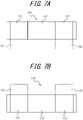
- Figs. 7A and 7B and Figs. 8A and 8B are diagrams each illustrating an example of a layout in which the vertical length of the composite image is shorter than that of FIG. 5 and FIG. 6 .
- Figs. 7A and 7B are layout variations in the first mode.
- the first captured image 111 is displayed on the left side.
- the first captured image 111 is a portion extracted from the vertically long image so as to remove the lower protruded portion 121.
- the second captured image 112 is displayed on the right side.
- the second captured image 112 is a portion extracted from the vertically long image so as to remove the lower protruded portion 122.
- the third captured image 113 is displayed on the middle.
- the layout illustrated in FIG. 7A is suitable when the moving body 61 is travelling at a normal speed.
- the first captured image 111 is displayed on the left side.
- the first captured image 111 is a portion extracted from the vertically long image so as to remove the upper protruded portion 121.
- the second captured image 112 is displayed on the right side.
- the second captured image 112 is a portion extracted from the vertically long image so as to remove the upper protruded portion 122.
- the third captured image 113 is displayed on the middle.
- the layout illustrated in FIG. 7B is suitable when the moving body 61 is backing into a parking space.
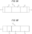
- Figs. 8A and 8B are layout variations in the second mode.
- the first captured image 111 is displayed on the left side.
- the first captured image 111 is a portion extracted from the horizontally long image so as to remove the left protruded portion 121.
- the second captured image 112 is displayed on the right side.
- the second captured image 112 is a portion extracted from the horizontally long image so as to remove the right protruded portion 122.
- the third captured image 113 is displayed on the middle.
- the size of the first captured image 111 is the same as that of the second captured image 112.
- the layout illustrated in FIG. 8A is suitable when the moving body 61 is travelling at a high speed, for example.
- the first captured image 111 is displayed on the left side.
- the first captured image 111 is a portion extracted from the horizontally long image so as remove the left protruded portion 121.
- the second captured image 112 is displayed on the right side.
- the third captured image 113 is displayed on the middle.
- the second captured image 112 is larger than the first captured image 111 in size.
- the layout illustrated in FIG. 8B is suitable when the moving body 61 turns right or merges into a fast lane, for example.
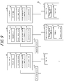
- a camera monitoring system 2 according to Variation 1 of an embodiment of this disclosure will be described with reference to FIG. 9 .
- the camera monitoring system 2 has a first camera 10, a first drive unit 15, a second camera 20, a second drive unit 25, a third camera 30, a monitor 40, an image processing device 50 and a controller 70.
- the first drive unit 15 drives rotation of the first camera 10.
- the first drive unit 15 can rotate the first camera 10 without changing an optical axis or can rotate the first camera 10 with the optical axis tilted.
- the second drive unit 25 drives rotation of the second camera 20.
- the second drive unit 25 can rotate the second camera 20 without changing the optical axis or can rotate the second camera 20 with the optical axis tilted.
- the controller 70 controls the operation of the first drive unit 15 and the second drive unit 25.
- the controller 70 includes a communication module 71 and a processor 72.
- the communication module 71 may include a communication interface that can communicate with a variety of external devices.
- the external device may include, for example, the first camera 10, the first drive unit 15, the second camera 20, the second drive unit 25, the third camera 30, the monitor 40, the image processing device 50, Electronic Control Unit or Engine Control Unit (ECU) provided in the moving body 61, a speed sensor, an acceleration sensor, a rotation angle sensor, a steering rudder angle sensor, an engine speed sensor, an accelerator sensor, a brake sensor, an illuminance sensor, a raindrop sensor, a travel distance sensor, a millimeter-wave radar, an obstacle detection device using a ultrasonic sonar, Electronic Toll Collection System (ETC) receiver, Global Positioning System (GPS) device, a navigation device, an internet server, a mobile phone and the like.
- ETC Electronic Toll Collection System
- GPS Global Positioning System
- the communication module 71 may include a communication interface for inter-pedestrian/vehicle communication, inter road/vehicle communication and inter vehicle communication.
- the communication module 71 may include a receiver corresponding to an optical beacon of Dedicated Short-Range Communication (DSRC: narrow band communication system) and Vehicle Information and Communication System (VICS) provided in Japan.
- DSRC Dedicated Short-Range Communication
- VICS Vehicle Information and Communication System
- the communication module 71 may include a receiver corresponding to a road traffic information providing system provided in other countries.
- the communication module 71 may be able to obtain a variety of information from an external device.
- the communication module 71 may be able to obtain the moving body information and the environmental information.
- the processor 72 includes one or more processors.
- the processor 72 controls overall operation of the controller 70.
- the processor 72 controls operation of the first drive unit 15 and the second drive unit 25.
- the first lens 11 of the first camera 10 and the second lens 21 of the second camera 20 are not super-wide-angle lenses.
- the range of the first captured image captured by the first camera 10 is not wide enough to allow both vertically and horizontally long images each including a desired range to be extracted from the first captured image.
- the super-wide-angle range needs a lot of lenses to secure the performance. Thus there is an increase in size of the lens, which causes an increase in cost.
- the camera monitoring system 2 according to Variation 1 does not need the first lens 11 and the second lens 21 to be super-wide-angle lenses, and thus a cost can be reduced.
- the first image sensor 12 and the second image sensor 22 of the camera monitoring system 2 captures an image of a rectangular range.
- the first drive unit 15 can dispose the first captured image horizontally long or vertically long by rotating the first camera 10.
- the second drive unit 25 can dispose the second captured image horizontally long or vertically long by rotating the second camera 20.
- FIG. 10A illustrates a state of the captured range when the first image sensor 12 is disposed horizontally long.
- FIG. 10B illustrates a state of the captured range when the first image sensor 12 is disposed vertically long.
- the first captured image is horizontally long, and when disposed as illustrated in FIG. 10B , the first captured image is vertically long.
- the first controller 14 of the first camera 10 converts the first captured image such that the upper portion of the first camera 10 coincides with the upper portion of the first captured image, and transmits the first captured image to the image processing device 50. Conversion of the first captured image may be performed by the image processor 53 of the image processing device 50.
- the second controller 24 of the second camera 20 converts the second captured image such that the upper portion of the second camera 20 coincides with the upper portion of the second captured image, and transmits the second captured image to the image processing device 50. Conversion of the second captured image may be performed by the image processor 53 of the image processing device 50.
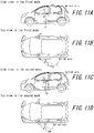
- Figs. 11A to 11D each illustrates an example of a captured range of the first camera 10 in the first mode and the second mode.
- the first drive unit 15 rotates the first camera 10 without changing the optical axis.
- FIG. 11A is a side view in the first mode.
- FIG. 11B is a top view in the first mode.
- FIG. 11C is a side view in the second mode.
- FIG. 11D is a top view in the second mode.
- the vertical range 101 captured by the first camera 10 in the first mode is larger than the vertical range 103 captured by the first camera 10 in the second mode.
- the horizontal range 104 captured by the first camera 10 in the second mode is larger than the horizontal range 102 of the first captured image captured by the first camera 10 in the first mode.
- Figs. 12A to 12D each illustrates an example of a captured range of the first camera 10 in the first mode and the second mode.
- the first drive unit 15 rotates the first camera 10 with the optical axis tilted.
- the first drive unit 15 sets the orientation of the optical axis more upward and outward than that in the first mode. In this manner, the orientation of the optical axis is changed depending on whether the mode is the first mode or the second mode, and as a result the driver 62 can observe a range suitable for the situation.
- FIG. 12A is a side view in the first mode
- FIG. 12B is a top view in the first mode
- FIG. 12C is a side view in the second mode
- FIG. 12D is a top view in the second mode.
- the vertical range 101 captured by the first camera 10 in the first mode is larger than the vertical range 103 captured by the first camera 10 in the second mode.
- the horizontal range 104 captured by the first camera 10 in the second mode is larger than the horizontal range 102 of the first captured image captured by the first camera 10 in the first mode.
- FIG. 13 illustrates an example of a mechanism for rotating the first camera 10 by the first drive unit 15.
- the first camera 10 has a gear 131 fixed to a housing of the first camera 10.
- the first drive unit 15 has a gear 132 engaged with the gear 131.
- the first drive unit 15 drives the gear 131 by rotating the gear 132 to rotate the first camera 10.
- the second drive unit 25 can rotate the second camera 20.
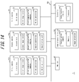
- a camera monitoring system 3 according to Variation 2 of an embodiment of this disclosure will be described with reference to FIG. 14 .
- the camera monitoring system 3 has a first camera 10a, a second camera 20a, a third camera 30, a monitor 40, an image processing device 50 and a controller 70.
- the first camera 10a includes a first drive unit 15 in addition to those included in the first camera 10 illustrated in FIG. 1 .
- the second camera 20a includes a second drive unit 25 in addition to those included in the second camera 20 illustrated in FIG. 1 .
- the first drive unit 15 integrally drives and rotates the first lens 11 and the first image sensor 12, or drives and rotates only the first image sensor 12.
- the second drive unit 25 integrally drives and rotates the second lens 21 and the second image sensor 22, or drives and rotates only the second image sensor 22.
- FIG. 15 illustrates an example of a mechanism in which the first drive unit 15 integrally rotates the first lens 11 and the first image sensor 12.
- the first lens 11 and the first image sensor 12 are coupled such that they are integrally rotated.
- the first lens 11 has a gear 133 fixed to the first lens 11.
- the first drive unit 15 includes a gear 134 engaged with the gear 133.
- the first drive unit 15 drives the gear 133 by rotating the gear 134 to integrally rotate the first lens 11 and the first image sensor 12.
- the second drive unit 25 can integrally rotate the second lens 21 and the second image sensor 22.
- FIG. 16 illustrates an example of a mechanism in which the first drive unit 15 rotates only the first image sensor 12.
- the first lens 11 and the first image sensor 12 are configured such that the first image sensor 12 can rotate independently from the first lens 11.
- the first image sensor 12 has a gear 135 fixed to the first image sensor 12.
- the first drive unit 15 includes a gear 136 engaged with the gear 135.
- the first drive unit 15 drives the gear 135 by rotating the gear 136 to rotate only the first image sensor 12.
- the second drive unit 25 can rotate only the second image sensor 22.
- Variation 2 is the same as Variation 1 except the rotation mechanism, and thus explanation thereof will be omitted.
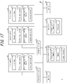
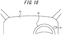
- a camera monitoring system 4 according to Variation 3 of an embodiment of this disclosure will be described with reference to FIG. 17 .
- the camera monitoring system 4 according to Variation 3 includes a switch 80 in addition to those included in the camera monitoring system 2 according to Variation 1.
- the switch 80 is a switch configured to switch between the first mode and the second mode.
- the first drive unit 15 rotates the first camera 10 such that the first captured image will be vertically long.
- the second drive unit 25 rotates the second camera 20 such that the second captured image will be vertically long.
- the driver 62 switches to the second mode by the switch 80
- the first drive unit 15 rotates the first camera 10 such that the first captured image will be horizontally long.
- the second drive unit 25 rotates the second camera 20 such that the second captured image will be horizontally long.
- the switch 80 may be located at any position in the moving body 61 as far as the driver 62 can operates it during driving of the moving body 61.
- the switch 80 is located on the right on the dashboard 63 behind the steering wheel 64.
- the switch 80 may be attached to the steering wheel 64.
- the switch 80 is not limited to a physical switch, and may be displayed as a switch button on a display of car navigation.
- the image processor 53 changes a layout of a composite image including a first captured image, a second captured image and a third captured image according to at least either the moving body information or the environmental information.
- the driver 62 who visually confirms a composite image can recognize an area suitable for the state of the moving body 61.
- the technical convenience of displaying a captured image of outside the moving body 61 is improved.
- each component and function of each of camera monitoring systems 1 to 4 may be rearranged.
- a part or all of components and functions of the image processing device 50 may be included in any one of the first camera 10, the second camera 20, the third camera 30 and the monitor 40.
- a part of components of the camera monitoring systems 1 to 4 may be disposed outside the moving body 61.
- the image processing device 50 and the like may be realized as a communication device such as a mobile phone or an external server and may be connected wirelessly or wired with other components of the camera monitoring systems 1 to 4.
Landscapes
- Engineering & Computer Science (AREA)
- Multimedia (AREA)
- Signal Processing (AREA)
- Mechanical Engineering (AREA)
- Closed-Circuit Television Systems (AREA)
- Studio Devices (AREA)
- Fittings On The Vehicle Exterior For Carrying Loads, And Devices For Holding Or Mounting Articles (AREA)
- Traffic Control Systems (AREA)
Claims (8)
- Système de surveillance par caméra (2, 3, 4), comprenant :une première caméra (10) configurée pour capturer une image d'une zone comprenant une zone prédéterminée sur le côté gauche d'un véhicule ;une deuxième caméra (20) configurée pour capturer une image d'une zone comprenant une zone prédéterminée sur le côté droit du véhicule ;une troisième caméra (30) configurée pour capturer une image d'une zone comprenant une zone prédéterminée derrière le véhicule ;un moniteur (40) configuré pour afficher une image composite comprenant une première image capturée, capturée par la première caméra (10), une deuxième image capturée, capturée par la deuxième caméra (20) et une troisième image capturée, capturée par la troisième caméra (30) ; etun processeur d'image (53) configuré pourcommander une disposition de l'image composite, etchanger la disposition en fonction d'au moins une information de corps en mouvement ou une information environnementale,dans lequel le processeur d'image (53) commute un rapport d'aspect de la première image capturée et de la deuxième image capturée affichées sur le moniteur (40) selon au moins soit l'information de corps en mouvement, soit l'information environnementale ;caractérisé parle système de surveillance par caméra (2, 3, 4) comprenant en outre :une première unité d'entraînement (15) configurée pour entraîner une rotation de la première caméra (10) ;une deuxième unité d'entraînement (25) configurée pour entraîner une rotation de la deuxième caméra (20) ; etun contrôleur (70) configuré pour commander la première unité d'entraînement (15) et la deuxième unité d'entraînement (25), commuter un rapport d'aspect de la première image capturée en faisant tourner la première caméra (10), et commuter un rapport d'aspect de la deuxième image capturée en faisant tourner la deuxième caméra (20) ; oudans lequella première caméra (10) comprend un premier objectif (11), un premier capteur d'image (12) et une première unité d'entraînement (15) configurée pour entraîner la rotation du premier objectif (11) et du premier capteur d'image (12) ;la deuxième caméra (20) comprend un deuxième objectif (21), un deuxième capteur d'image (22) et une deuxième unité d'entraînement (25) configurée pour entraîner la rotation du deuxième objectif (21) et du deuxième capteur d'image (22) ;le système de surveillance de caméra (2, 3, 4) comprend en outre un contrôleur (70) configuré pour commander la première unité d'entraînement (15) et la deuxième unité d'entraînement (15), commuter un rapport d'aspect de la première image capturée en faisant tourner le premier objectif (11) et le premier capteur d'image (12), et commuter un rapport d'aspect de la deuxième image capturée en faisant tourner le deuxième objectif (21) et le deuxième capteur d'image (22) ; oudans lequella première caméra (10) comprend un premier capteur d'image (12) et une première unité d'entraînement (15) configurée pour entraîner la rotation du premier capteur d'image (12) ;la deuxième caméra (20) comprend un deuxième capteur d'image (22) et une deuxième unité d'entraînement (25) configurée pour entraîner la rotation du deuxième capteur d'image (22) ;le système de surveillance de caméra (2, 3, 4) comprend en outre un contrôleur (70) configuré pour commander la première unité d'entraînement (15) et la deuxième unité d'entraînement (25), commuter un rapport d'aspect de la première image capturée en faisant tourner le premier capteur d'image (12), et commuter un rapport d'aspect de la deuxième image capturée en faisant tourner le deuxième capteur d'image (22) .
- Système de surveillance par caméra (2, 3, 4) selon la revendication 1, dans lequel le processeur d'image (53) commute vers une disposition dans laquelle la première image capturée et la deuxième image capturée sont affichées horizontalement en longueur en réponse à la détection d'un fonctionnement du commutateur de clignotant du véhicule.
- Système de surveillance par caméra (2, 3, 4) selon la revendication 1 ou 2, dans lequel le processeur d'image (53) commute vers une disposition dans laquelle la première image capturée et la deuxième image capturée sont affichées horizontalement en longueur lorsqu'une vitesse du véhicule devient supérieure ou égale à une vitesse prédéterminée.
- Système de surveillance par caméra (2, 3, 4) selon l'une quelconque des revendications 1 à 3, dans lequel le processeur d'image (53) commute vers une disposition dans laquelle la première image capturée et la deuxième image capturée sont affichées horizontalement en longueur lorsqu'il est détecté que le véhicule se déplace sur une route ayant plusieurs voies.
- Système de surveillance par caméra (2, 3, 4) selon l'une quelconque des revendications 1 à 4, dans lequel le processeur d'image (53) commute vers une disposition dans laquelle la première image capturée et la deuxième image capturée sont affichées verticalement en longueur lorsqu'une vitesse du véhicule est mise en marche arrière.
- Système de surveillance par caméra (2, 3, 4) selon l'une quelconque des revendications 1 à 5, dans lequel la première caméra (10), la deuxième caméra (20) et la troisième caméra (30) sont des dispositifs configurés pour capturer une image d'une plage qui inclut une plage spécifiée dans le règlement des Nations unies n° 46 sur la vision indirecte.
- Véhicule comprenant un système de surveillance par caméra (2, 3, 4) selon l'une quelconque des revendications 1 à 6.
- Procédé de traitement d'image pour un système de surveillance par caméra (2, 3, 4) selon l'une quelconque des revendications 1 à 6, le procédé comprenant :la capture, par la première caméra (10), d'une image d'une zone comprenant une zone prédéterminée sur le côté gauche d'un véhicule ;la capture, par la deuxième caméra (20), d'une image d'une zone comprenant une zone prédéterminée sur le côté droit du véhicule ;la capture, par la troisième caméra (30), d'une image d'une zone comprenant une zone prédéterminée derrière le véhicule ;la commande, par le processeur d'image (53), d'une disposition d'une image composite affichée sur le moniteur (40) selon au moins soit une information de corps en mouvement, soit une information environnementale ;l'affichage, par le moniteur (40), de l'image composite comprenant une première image capturée, capturée par la première caméra (10), une deuxième image capturée, capturée par la deuxième caméra (20) et une troisième image capturée, capturée par la troisième caméra (30), la disposition de l'image composite étant commandée par le processeur d'image (53) ;la commutation, par le processeur d'image (53), d'un rapport d'aspect de la première image capturée et de la deuxième image capturée affichées sur le moniteur (40) selon au moins soit l'information de corps en mouvement, soit l'information environnementale ; etcaractérisé en ce qu'il comprend :l'entraînement en rotation, par la première unité d'entraînement (15), de la première caméra (10), l'entraînement en rotation, par la deuxième unité d'entraînement (25), de la deuxième caméra (20), et, par le contrôleur (70) commandant la première unité d'entraînement (15) et la deuxième unité d'entraînement (25), la commutation d'un rapport d'aspect de la première image capturée en faisant tourner la première caméra (10), et la commutation d'un rapport d'aspect de la deuxième image capturée en faisant tourner la deuxième caméra (20) ; oul'entraînement en rotation, par la première unité d'entraînement (15), du premier objectif (11) et du premier capteur d'image (12), l'entraînement en rotation, par la deuxième unité d'entraînement (25), du deuxième objectif (21) et du deuxième capteur d'image (22), et, par le contrôleur (70) commandant la première unité d'entraînement (15) et la deuxième unité d'entraînement (15), la commutation d'un rapport d'aspect de la première image capturée en faisant tourner le premier objectif (11) et le premier capteur d'image (12), et la commutation d'un rapport d'aspect de la deuxième image capturée en faisant tourner le deuxième objectif (21) et le deuxième capteur d'image (22) ; oul'entraînement en rotation, par la première unité d'entraînement (15), du premier capteur d'image (12), l'entraînement en rotation, par la deuxième unité d'entraînement (25), du deuxième capteur d'image (22), et, par le contrôleur (70) commandant la première unité d'entraînement (15) et la deuxième unité d'entraînement (25), la commutation d'un rapport d'aspect de la première image capturée en faisant tourner le premier capteur d'image (12), et la commutation d'un rapport d'aspect de la deuxième image capturée en faisant tourner le deuxième capteur d'image (22).
Applications Claiming Priority (2)
| Application Number | Priority Date | Filing Date | Title |
|---|---|---|---|
| JP2016233490A JP6626817B2 (ja) | 2016-11-30 | 2016-11-30 | カメラモニタシステム、画像処理装置、車両及び画像処理方法 |
| PCT/JP2017/041284 WO2018101063A1 (fr) | 2016-11-30 | 2017-11-16 | Caméra et système de surveillance, dispositif de traitement d'image, véhicule et procédé de traitement d'image |
Publications (3)
| Publication Number | Publication Date |
|---|---|
| EP3550819A1 EP3550819A1 (fr) | 2019-10-09 |
| EP3550819A4 EP3550819A4 (fr) | 2020-07-15 |
| EP3550819B1 true EP3550819B1 (fr) | 2022-08-24 |
Family
ID=62242818
Family Applications (1)
| Application Number | Title | Priority Date | Filing Date |
|---|---|---|---|
| EP17876036.9A Active EP3550819B1 (fr) | 2016-11-30 | 2017-11-16 | Système de surveillance par caméra, véhicule et procédé de traitement d'image |
Country Status (4)
| Country | Link |
|---|---|
| US (1) | US10893214B2 (fr) |
| EP (1) | EP3550819B1 (fr) |
| JP (1) | JP6626817B2 (fr) |
| WO (1) | WO2018101063A1 (fr) |
Families Citing this family (5)
| Publication number | Priority date | Publication date | Assignee | Title |
|---|---|---|---|---|
| US11165932B2 (en) * | 2015-12-22 | 2021-11-02 | Kyocera Corporation | Imaging apparatus, imaging system, vehicle and foreign matter determination method |
| JP6890288B2 (ja) * | 2018-03-28 | 2021-06-18 | パナソニックIpマネジメント株式会社 | 画像処理装置、画像表示システムおよび画像処理方法 |
| KR20200055596A (ko) * | 2018-11-13 | 2020-05-21 | 삼성전자주식회사 | 차량에 탑재되는 단말 장치가 영상을 전송하는 방법 및 차량의 주행을 제어하는 원격 제어 장치가 영상을 수신하는 방법 |
| JP7440235B2 (ja) | 2019-09-26 | 2024-02-28 | フォルシアクラリオン・エレクトロニクス株式会社 | 表示制御装置、及び表示制御方法 |
| US20230367098A1 (en) * | 2022-05-16 | 2023-11-16 | GM Global Technology Operations LLC | Methods and systems for automated dynamic lens utilization |
Family Cites Families (17)
| Publication number | Priority date | Publication date | Assignee | Title |
|---|---|---|---|---|
| JPH10257482A (ja) * | 1997-03-13 | 1998-09-25 | Nissan Motor Co Ltd | 車両周辺状況表示装置 |
| EP0949818A3 (fr) * | 1998-04-07 | 2000-10-25 | Matsushita Electric Industrial Co., Ltd. | Appareil de visualisation embarqué, système de transmission d'image, appareil de transmission d'image, et appareil de capture d'image |
| JP3298851B2 (ja) | 1999-08-18 | 2002-07-08 | 松下電器産業株式会社 | 多機能車載カメラシステムと多機能車載カメラの画像表示方法 |
| US6559761B1 (en) * | 2001-10-05 | 2003-05-06 | Ford Global Technologies, Llc | Display system for vehicle environment awareness |
| KR100482598B1 (ko) * | 2003-04-21 | 2005-04-14 | 현대자동차주식회사 | 차간거리 제어방법 및 장치 |
| JP2006264574A (ja) | 2005-03-25 | 2006-10-05 | Matsushita Electric Ind Co Ltd | 車載カメラ及び車載カメラシステム |
| WO2007032427A1 (fr) | 2005-09-16 | 2007-03-22 | Pioneer Corporation | Dispositif d’assistance de conduite, méthode de commande d’imagerie, programme de commande d’imagerie et support d’enregistrement |
| JP2007237785A (ja) * | 2006-03-06 | 2007-09-20 | National Univ Corp Shizuoka Univ | 車載用情報提示システム |
| US20090128630A1 (en) * | 2006-07-06 | 2009-05-21 | Nissan Motor Co., Ltd. | Vehicle image display system and image display method |
| JP5120880B2 (ja) * | 2007-10-15 | 2013-01-16 | アルパイン株式会社 | 画像処理装置及び画像処理方法 |
| JP5500369B2 (ja) * | 2009-08-03 | 2014-05-21 | アイシン精機株式会社 | 車両周辺画像生成装置 |
| JP5077307B2 (ja) * | 2009-08-05 | 2012-11-21 | 株式会社デンソー | 車両周囲画像表示制御装置 |
| US8310520B2 (en) * | 2009-08-19 | 2012-11-13 | Avaya Inc. | Flexible decomposition and recomposition of multimedia conferencing streams using real-time control information |
| JP5251947B2 (ja) * | 2010-09-17 | 2013-07-31 | 日産自動車株式会社 | 車両用画像表示装置 |
| JP6364702B2 (ja) * | 2013-03-29 | 2018-08-01 | アイシン精機株式会社 | 画像表示制御装置、画像表示システム、および表示ユニット |
| JP6261542B2 (ja) * | 2015-06-10 | 2018-01-17 | 株式会社デンソーテン | 画像処理装置および画像処理方法 |
| US20170094227A1 (en) * | 2015-09-25 | 2017-03-30 | Northrop Grumman Systems Corporation | Three-dimensional spatial-awareness vision system |
-
2016
- 2016-11-30 JP JP2016233490A patent/JP6626817B2/ja active Active
-
2017
- 2017-11-16 EP EP17876036.9A patent/EP3550819B1/fr active Active
- 2017-11-16 WO PCT/JP2017/041284 patent/WO2018101063A1/fr unknown
- 2017-11-16 US US16/464,776 patent/US10893214B2/en active Active
Also Published As
| Publication number | Publication date |
|---|---|
| WO2018101063A1 (fr) | 2018-06-07 |
| US10893214B2 (en) | 2021-01-12 |
| EP3550819A1 (fr) | 2019-10-09 |
| JP2018093311A (ja) | 2018-06-14 |
| US20190394410A1 (en) | 2019-12-26 |
| EP3550819A4 (fr) | 2020-07-15 |
| JP6626817B2 (ja) | 2019-12-25 |
Similar Documents
| Publication | Publication Date | Title |
|---|---|---|
| EP3550819B1 (fr) | Système de surveillance par caméra, véhicule et procédé de traitement d'image | |
| US11961162B2 (en) | Imaging apparatus, image processing apparatus, display system, and vehicle | |
| CN108216032B (zh) | 车辆用环视监控装置、车辆运行控制装置以及车辆 | |
| US20190124277A1 (en) | Shooting control apparatus and shooting control method as well as shooting apparatus | |
| US9218057B2 (en) | Vehicular display system | |
| US9126483B2 (en) | Vehicular display system | |
| CN109249939B (zh) | 用于车辆的驱动系统和车辆 | |
| CN111788085B (zh) | 信息显示装置 | |
| US20160229341A1 (en) | Apparatus and method for a safety system of cameras for advantageously viewing vehicular traffic by the driver | |
| CN110574357B (zh) | 成像控制设备、用于控制成像控制设备的方法以及移动体 | |
| JP6930971B2 (ja) | 表示装置、表示システム、および移動体 | |
| US11942494B2 (en) | Imaging device | |
| US11030468B2 (en) | Image processing apparatus | |
| US11100353B2 (en) | Apparatus of controlling region of interest of image and method for controlling the same | |
| JP2018085584A (ja) | 画像処理装置、撮像装置、および表示システム | |
| JP2018107620A (ja) | 撮像システム、移動体、および制御方法 | |
| JP6712942B2 (ja) | 画像処理装置、撮像装置、および表示システム | |
| JP6720063B2 (ja) | 画像処理装置、撮像装置、および表示システム | |
| JP3231104U (ja) | レーダー装置に対応する移動車両用画像撮影装置 | |
| JP6759072B2 (ja) | 画像処理装置、撮像装置、および表示システム | |
| CN112567427A (zh) | 图像处理装置、图像处理方法和程序 | |
| CN117222548A (zh) | 控制车载摄像头的视角的方法、装置以及车辆 | |
| JP2024073899A (ja) | 撮像素子 |
Legal Events
| Date | Code | Title | Description |
|---|---|---|---|
| STAA | Information on the status of an ep patent application or granted ep patent |
Free format text: STATUS: THE INTERNATIONAL PUBLICATION HAS BEEN MADE |
|
| PUAI | Public reference made under article 153(3) epc to a published international application that has entered the european phase |
Free format text: ORIGINAL CODE: 0009012 |
|
| STAA | Information on the status of an ep patent application or granted ep patent |
Free format text: STATUS: REQUEST FOR EXAMINATION WAS MADE |
|
| 17P | Request for examination filed |
Effective date: 20190529 |
|
| AK | Designated contracting states |
Kind code of ref document: A1 Designated state(s): AL AT BE BG CH CY CZ DE DK EE ES FI FR GB GR HR HU IE IS IT LI LT LU LV MC MK MT NL NO PL PT RO RS SE SI SK SM TR |
|
| AX | Request for extension of the european patent |
Extension state: BA ME |
|
| DAV | Request for validation of the european patent (deleted) | ||
| DAX | Request for extension of the european patent (deleted) | ||
| A4 | Supplementary search report drawn up and despatched |
Effective date: 20200612 |
|
| RIC1 | Information provided on ipc code assigned before grant |
Ipc: B60R 1/00 20060101ALI20200606BHEP Ipc: H04N 5/232 20060101AFI20200606BHEP Ipc: H04N 7/18 20060101ALI20200606BHEP |
|
| GRAP | Despatch of communication of intention to grant a patent |
Free format text: ORIGINAL CODE: EPIDOSNIGR1 |
|
| STAA | Information on the status of an ep patent application or granted ep patent |
Free format text: STATUS: GRANT OF PATENT IS INTENDED |
|
| INTG | Intention to grant announced |
Effective date: 20220321 |
|
| RIN1 | Information on inventor provided before grant (corrected) |
Inventor name: SUNAGA, TOSHIHIRO |
|
| GRAS | Grant fee paid |
Free format text: ORIGINAL CODE: EPIDOSNIGR3 |
|
| GRAA | (expected) grant |
Free format text: ORIGINAL CODE: 0009210 |
|
| STAA | Information on the status of an ep patent application or granted ep patent |
Free format text: STATUS: THE PATENT HAS BEEN GRANTED |
|
| AK | Designated contracting states |
Kind code of ref document: B1 Designated state(s): AL AT BE BG CH CY CZ DE DK EE ES FI FR GB GR HR HU IE IS IT LI LT LU LV MC MK MT NL NO PL PT RO RS SE SI SK SM TR |
|
| REG | Reference to a national code |
Ref country code: CH Ref legal event code: EP |
|
| REG | Reference to a national code |
Ref country code: DE Ref legal event code: R096 Ref document number: 602017061101 Country of ref document: DE |
|
| REG | Reference to a national code |
Ref country code: IE Ref legal event code: FG4D |
|
| REG | Reference to a national code |
Ref country code: AT Ref legal event code: REF Ref document number: 1514498 Country of ref document: AT Kind code of ref document: T Effective date: 20220915 |
|
| REG | Reference to a national code |
Ref country code: DE Ref legal event code: R079 Ref document number: 602017061101 Country of ref document: DE Free format text: PREVIOUS MAIN CLASS: H04N0005232000 Ipc: H04N0023600000 |
|
| REG | Reference to a national code |
Ref country code: LT Ref legal event code: MG9D |
|
| REG | Reference to a national code |
Ref country code: NL Ref legal event code: MP Effective date: 20220824 |
|
| PG25 | Lapsed in a contracting state [announced via postgrant information from national office to epo] |
Ref country code: SE Free format text: LAPSE BECAUSE OF FAILURE TO SUBMIT A TRANSLATION OF THE DESCRIPTION OR TO PAY THE FEE WITHIN THE PRESCRIBED TIME-LIMIT Effective date: 20220824 Ref country code: RS Free format text: LAPSE BECAUSE OF FAILURE TO SUBMIT A TRANSLATION OF THE DESCRIPTION OR TO PAY THE FEE WITHIN THE PRESCRIBED TIME-LIMIT Effective date: 20220824 Ref country code: PT Free format text: LAPSE BECAUSE OF FAILURE TO SUBMIT A TRANSLATION OF THE DESCRIPTION OR TO PAY THE FEE WITHIN THE PRESCRIBED TIME-LIMIT Effective date: 20221226 Ref country code: NO Free format text: LAPSE BECAUSE OF FAILURE TO SUBMIT A TRANSLATION OF THE DESCRIPTION OR TO PAY THE FEE WITHIN THE PRESCRIBED TIME-LIMIT Effective date: 20221124 Ref country code: NL Free format text: LAPSE BECAUSE OF FAILURE TO SUBMIT A TRANSLATION OF THE DESCRIPTION OR TO PAY THE FEE WITHIN THE PRESCRIBED TIME-LIMIT Effective date: 20220824 Ref country code: LV Free format text: LAPSE BECAUSE OF FAILURE TO SUBMIT A TRANSLATION OF THE DESCRIPTION OR TO PAY THE FEE WITHIN THE PRESCRIBED TIME-LIMIT Effective date: 20220824 Ref country code: LT Free format text: LAPSE BECAUSE OF FAILURE TO SUBMIT A TRANSLATION OF THE DESCRIPTION OR TO PAY THE FEE WITHIN THE PRESCRIBED TIME-LIMIT Effective date: 20220824 Ref country code: FI Free format text: LAPSE BECAUSE OF FAILURE TO SUBMIT A TRANSLATION OF THE DESCRIPTION OR TO PAY THE FEE WITHIN THE PRESCRIBED TIME-LIMIT Effective date: 20220824 |
|
| REG | Reference to a national code |
Ref country code: AT Ref legal event code: MK05 Ref document number: 1514498 Country of ref document: AT Kind code of ref document: T Effective date: 20220824 |
|
| PG25 | Lapsed in a contracting state [announced via postgrant information from national office to epo] |
Ref country code: PL Free format text: LAPSE BECAUSE OF FAILURE TO SUBMIT A TRANSLATION OF THE DESCRIPTION OR TO PAY THE FEE WITHIN THE PRESCRIBED TIME-LIMIT Effective date: 20220824 Ref country code: IS Free format text: LAPSE BECAUSE OF FAILURE TO SUBMIT A TRANSLATION OF THE DESCRIPTION OR TO PAY THE FEE WITHIN THE PRESCRIBED TIME-LIMIT Effective date: 20221224 Ref country code: HR Free format text: LAPSE BECAUSE OF FAILURE TO SUBMIT A TRANSLATION OF THE DESCRIPTION OR TO PAY THE FEE WITHIN THE PRESCRIBED TIME-LIMIT Effective date: 20220824 Ref country code: GR Free format text: LAPSE BECAUSE OF FAILURE TO SUBMIT A TRANSLATION OF THE DESCRIPTION OR TO PAY THE FEE WITHIN THE PRESCRIBED TIME-LIMIT Effective date: 20221125 |
|
| PG25 | Lapsed in a contracting state [announced via postgrant information from national office to epo] |
Ref country code: SM Free format text: LAPSE BECAUSE OF FAILURE TO SUBMIT A TRANSLATION OF THE DESCRIPTION OR TO PAY THE FEE WITHIN THE PRESCRIBED TIME-LIMIT Effective date: 20220824 Ref country code: RO Free format text: LAPSE BECAUSE OF FAILURE TO SUBMIT A TRANSLATION OF THE DESCRIPTION OR TO PAY THE FEE WITHIN THE PRESCRIBED TIME-LIMIT Effective date: 20220824 Ref country code: ES Free format text: LAPSE BECAUSE OF FAILURE TO SUBMIT A TRANSLATION OF THE DESCRIPTION OR TO PAY THE FEE WITHIN THE PRESCRIBED TIME-LIMIT Effective date: 20220824 Ref country code: DK Free format text: LAPSE BECAUSE OF FAILURE TO SUBMIT A TRANSLATION OF THE DESCRIPTION OR TO PAY THE FEE WITHIN THE PRESCRIBED TIME-LIMIT Effective date: 20220824 Ref country code: CZ Free format text: LAPSE BECAUSE OF FAILURE TO SUBMIT A TRANSLATION OF THE DESCRIPTION OR TO PAY THE FEE WITHIN THE PRESCRIBED TIME-LIMIT Effective date: 20220824 Ref country code: AT Free format text: LAPSE BECAUSE OF FAILURE TO SUBMIT A TRANSLATION OF THE DESCRIPTION OR TO PAY THE FEE WITHIN THE PRESCRIBED TIME-LIMIT Effective date: 20220824 |
|
| REG | Reference to a national code |
Ref country code: DE Ref legal event code: R097 Ref document number: 602017061101 Country of ref document: DE |
|
| PG25 | Lapsed in a contracting state [announced via postgrant information from national office to epo] |
Ref country code: SK Free format text: LAPSE BECAUSE OF FAILURE TO SUBMIT A TRANSLATION OF THE DESCRIPTION OR TO PAY THE FEE WITHIN THE PRESCRIBED TIME-LIMIT Effective date: 20220824 Ref country code: EE Free format text: LAPSE BECAUSE OF FAILURE TO SUBMIT A TRANSLATION OF THE DESCRIPTION OR TO PAY THE FEE WITHIN THE PRESCRIBED TIME-LIMIT Effective date: 20220824 |
|
| P01 | Opt-out of the competence of the unified patent court (upc) registered |
Effective date: 20230505 |
|
| PG25 | Lapsed in a contracting state [announced via postgrant information from national office to epo] |
Ref country code: MC Free format text: LAPSE BECAUSE OF FAILURE TO SUBMIT A TRANSLATION OF THE DESCRIPTION OR TO PAY THE FEE WITHIN THE PRESCRIBED TIME-LIMIT Effective date: 20220824 Ref country code: AL Free format text: LAPSE BECAUSE OF FAILURE TO SUBMIT A TRANSLATION OF THE DESCRIPTION OR TO PAY THE FEE WITHIN THE PRESCRIBED TIME-LIMIT Effective date: 20220824 |
|
| PLBE | No opposition filed within time limit |
Free format text: ORIGINAL CODE: 0009261 |
|
| REG | Reference to a national code |
Ref country code: CH Ref legal event code: PL |
|
| STAA | Information on the status of an ep patent application or granted ep patent |
Free format text: STATUS: NO OPPOSITION FILED WITHIN TIME LIMIT |
|
| REG | Reference to a national code |
Ref country code: BE Ref legal event code: MM Effective date: 20221130 |
|
| PG25 | Lapsed in a contracting state [announced via postgrant information from national office to epo] |
Ref country code: LI Free format text: LAPSE BECAUSE OF NON-PAYMENT OF DUE FEES Effective date: 20221130 Ref country code: CH Free format text: LAPSE BECAUSE OF NON-PAYMENT OF DUE FEES Effective date: 20221130 |
|
| 26N | No opposition filed |
Effective date: 20230525 |
|
| PG25 | Lapsed in a contracting state [announced via postgrant information from national office to epo] |
Ref country code: SI Free format text: LAPSE BECAUSE OF FAILURE TO SUBMIT A TRANSLATION OF THE DESCRIPTION OR TO PAY THE FEE WITHIN THE PRESCRIBED TIME-LIMIT Effective date: 20220824 Ref country code: LU Free format text: LAPSE BECAUSE OF NON-PAYMENT OF DUE FEES Effective date: 20221116 |
|
| PG25 | Lapsed in a contracting state [announced via postgrant information from national office to epo] |
Ref country code: IE Free format text: LAPSE BECAUSE OF NON-PAYMENT OF DUE FEES Effective date: 20221116 |
|
| PGFP | Annual fee paid to national office [announced via postgrant information from national office to epo] |
Ref country code: GB Payment date: 20230928 Year of fee payment: 7 |
|
| PG25 | Lapsed in a contracting state [announced via postgrant information from national office to epo] |
Ref country code: BE Free format text: LAPSE BECAUSE OF NON-PAYMENT OF DUE FEES Effective date: 20221130 |
|
| PGFP | Annual fee paid to national office [announced via postgrant information from national office to epo] |
Ref country code: FR Payment date: 20230929 Year of fee payment: 7 |
|
| PGFP | Annual fee paid to national office [announced via postgrant information from national office to epo] |
Ref country code: DE Payment date: 20230929 Year of fee payment: 7 |
|
| PG25 | Lapsed in a contracting state [announced via postgrant information from national office to epo] |
Ref country code: HU Free format text: LAPSE BECAUSE OF FAILURE TO SUBMIT A TRANSLATION OF THE DESCRIPTION OR TO PAY THE FEE WITHIN THE PRESCRIBED TIME-LIMIT; INVALID AB INITIO Effective date: 20171116 |
|
| PG25 | Lapsed in a contracting state [announced via postgrant information from national office to epo] |
Ref country code: CY Free format text: LAPSE BECAUSE OF FAILURE TO SUBMIT A TRANSLATION OF THE DESCRIPTION OR TO PAY THE FEE WITHIN THE PRESCRIBED TIME-LIMIT Effective date: 20220824 |