EP3550709A1 - Electric vehicle, dc-dc convertor, and control method for dc-dc convertor - Google Patents
Electric vehicle, dc-dc convertor, and control method for dc-dc convertor Download PDFInfo
- Publication number
- EP3550709A1 EP3550709A1 EP17875909.8A EP17875909A EP3550709A1 EP 3550709 A1 EP3550709 A1 EP 3550709A1 EP 17875909 A EP17875909 A EP 17875909A EP 3550709 A1 EP3550709 A1 EP 3550709A1
- Authority
- EP
- European Patent Office
- Prior art keywords
- bridge
- switch tube
- mode
- controlling
- converter
- Prior art date
- Legal status (The legal status is an assumption and is not a legal conclusion. Google has not performed a legal analysis and makes no representation as to the accuracy of the status listed.)
- Granted
Links
Images

Classifications
-
- H—ELECTRICITY
- H02—GENERATION; CONVERSION OR DISTRIBUTION OF ELECTRIC POWER
- H02M—APPARATUS FOR CONVERSION BETWEEN AC AND AC, BETWEEN AC AND DC, OR BETWEEN DC AND DC, AND FOR USE WITH MAINS OR SIMILAR POWER SUPPLY SYSTEMS; CONVERSION OF DC OR AC INPUT POWER INTO SURGE OUTPUT POWER; CONTROL OR REGULATION THEREOF
- H02M3/00—Conversion of DC power input into DC power output
- H02M3/22—Conversion of DC power input into DC power output with intermediate conversion into AC
- H02M3/24—Conversion of DC power input into DC power output with intermediate conversion into AC by static converters
- H02M3/28—Conversion of DC power input into DC power output with intermediate conversion into AC by static converters using discharge tubes with control electrode or semiconductor devices with control electrode to produce the intermediate AC
- H02M3/325—Conversion of DC power input into DC power output with intermediate conversion into AC by static converters using discharge tubes with control electrode or semiconductor devices with control electrode to produce the intermediate AC using devices of a triode or a transistor type requiring continuous application of a control signal
- H02M3/335—Conversion of DC power input into DC power output with intermediate conversion into AC by static converters using discharge tubes with control electrode or semiconductor devices with control electrode to produce the intermediate AC using devices of a triode or a transistor type requiring continuous application of a control signal using semiconductor devices only
- H02M3/3353—Conversion of DC power input into DC power output with intermediate conversion into AC by static converters using discharge tubes with control electrode or semiconductor devices with control electrode to produce the intermediate AC using devices of a triode or a transistor type requiring continuous application of a control signal using semiconductor devices only having at least two simultaneously operating switches on the input side, e.g. "double forward" or "double (switched) flyback" converter
-
- H—ELECTRICITY
- H02—GENERATION; CONVERSION OR DISTRIBUTION OF ELECTRIC POWER
- H02M—APPARATUS FOR CONVERSION BETWEEN AC AND AC, BETWEEN AC AND DC, OR BETWEEN DC AND DC, AND FOR USE WITH MAINS OR SIMILAR POWER SUPPLY SYSTEMS; CONVERSION OF DC OR AC INPUT POWER INTO SURGE OUTPUT POWER; CONTROL OR REGULATION THEREOF
- H02M3/00—Conversion of DC power input into DC power output
- H02M3/22—Conversion of DC power input into DC power output with intermediate conversion into AC
- H02M3/24—Conversion of DC power input into DC power output with intermediate conversion into AC by static converters
- H02M3/28—Conversion of DC power input into DC power output with intermediate conversion into AC by static converters using discharge tubes with control electrode or semiconductor devices with control electrode to produce the intermediate AC
- H02M3/325—Conversion of DC power input into DC power output with intermediate conversion into AC by static converters using discharge tubes with control electrode or semiconductor devices with control electrode to produce the intermediate AC using devices of a triode or a transistor type requiring continuous application of a control signal
- H02M3/335—Conversion of DC power input into DC power output with intermediate conversion into AC by static converters using discharge tubes with control electrode or semiconductor devices with control electrode to produce the intermediate AC using devices of a triode or a transistor type requiring continuous application of a control signal using semiconductor devices only
- H02M3/337—Conversion of DC power input into DC power output with intermediate conversion into AC by static converters using discharge tubes with control electrode or semiconductor devices with control electrode to produce the intermediate AC using devices of a triode or a transistor type requiring continuous application of a control signal using semiconductor devices only in push-pull configuration
- H02M3/3376—Conversion of DC power input into DC power output with intermediate conversion into AC by static converters using discharge tubes with control electrode or semiconductor devices with control electrode to produce the intermediate AC using devices of a triode or a transistor type requiring continuous application of a control signal using semiconductor devices only in push-pull configuration with automatic control of output voltage or current
-
- B—PERFORMING OPERATIONS; TRANSPORTING
- B60—VEHICLES IN GENERAL
- B60L—PROPULSION OF ELECTRICALLY-PROPELLED VEHICLES; SUPPLYING ELECTRIC POWER FOR AUXILIARY EQUIPMENT OF ELECTRICALLY-PROPELLED VEHICLES; ELECTRODYNAMIC BRAKE SYSTEMS FOR VEHICLES IN GENERAL; MAGNETIC SUSPENSION OR LEVITATION FOR VEHICLES; MONITORING OPERATING VARIABLES OF ELECTRICALLY-PROPELLED VEHICLES; ELECTRIC SAFETY DEVICES FOR ELECTRICALLY-PROPELLED VEHICLES
- B60L53/00—Methods of charging batteries, specially adapted for electric vehicles; Charging stations or on-board charging equipment therefor; Exchange of energy storage elements in electric vehicles
- B60L53/20—Methods of charging batteries, specially adapted for electric vehicles; Charging stations or on-board charging equipment therefor; Exchange of energy storage elements in electric vehicles characterised by converters located in the vehicle
- B60L53/22—Constructional details or arrangements of charging converters specially adapted for charging electric vehicles
-
- H—ELECTRICITY
- H02—GENERATION; CONVERSION OR DISTRIBUTION OF ELECTRIC POWER
- H02J—ELECTRIC POWER NETWORKS; CIRCUIT ARRANGEMENTS OR SYSTEMS FOR SUPPLYING OR DISTRIBUTING ELECTRIC POWER; SYSTEMS FOR STORING ELECTRIC ENERGY
- H02J7/00—Circuit arrangements for charging or discharging batteries or for supplying loads from batteries
-
- H—ELECTRICITY
- H02—GENERATION; CONVERSION OR DISTRIBUTION OF ELECTRIC POWER
- H02M—APPARATUS FOR CONVERSION BETWEEN AC AND AC, BETWEEN AC AND DC, OR BETWEEN DC AND DC, AND FOR USE WITH MAINS OR SIMILAR POWER SUPPLY SYSTEMS; CONVERSION OF DC OR AC INPUT POWER INTO SURGE OUTPUT POWER; CONTROL OR REGULATION THEREOF
- H02M1/00—Details of apparatus for conversion
- H02M1/08—Circuits specially adapted for the generation of control voltages for semiconductor devices incorporated in static converters
- H02M1/088—Circuits specially adapted for the generation of control voltages for semiconductor devices incorporated in static converters for the simultaneous control of series or parallel connected semiconductor devices
-
- H—ELECTRICITY
- H02—GENERATION; CONVERSION OR DISTRIBUTION OF ELECTRIC POWER
- H02M—APPARATUS FOR CONVERSION BETWEEN AC AND AC, BETWEEN AC AND DC, OR BETWEEN DC AND DC, AND FOR USE WITH MAINS OR SIMILAR POWER SUPPLY SYSTEMS; CONVERSION OF DC OR AC INPUT POWER INTO SURGE OUTPUT POWER; CONTROL OR REGULATION THEREOF
- H02M1/00—Details of apparatus for conversion
- H02M1/36—Means for starting or stopping converters
-
- H—ELECTRICITY
- H02—GENERATION; CONVERSION OR DISTRIBUTION OF ELECTRIC POWER
- H02M—APPARATUS FOR CONVERSION BETWEEN AC AND AC, BETWEEN AC AND DC, OR BETWEEN DC AND DC, AND FOR USE WITH MAINS OR SIMILAR POWER SUPPLY SYSTEMS; CONVERSION OF DC OR AC INPUT POWER INTO SURGE OUTPUT POWER; CONTROL OR REGULATION THEREOF
- H02M3/00—Conversion of DC power input into DC power output
- H02M3/22—Conversion of DC power input into DC power output with intermediate conversion into AC
- H02M3/24—Conversion of DC power input into DC power output with intermediate conversion into AC by static converters
- H02M3/28—Conversion of DC power input into DC power output with intermediate conversion into AC by static converters using discharge tubes with control electrode or semiconductor devices with control electrode to produce the intermediate AC
- H02M3/325—Conversion of DC power input into DC power output with intermediate conversion into AC by static converters using discharge tubes with control electrode or semiconductor devices with control electrode to produce the intermediate AC using devices of a triode or a transistor type requiring continuous application of a control signal
- H02M3/335—Conversion of DC power input into DC power output with intermediate conversion into AC by static converters using discharge tubes with control electrode or semiconductor devices with control electrode to produce the intermediate AC using devices of a triode or a transistor type requiring continuous application of a control signal using semiconductor devices only
- H02M3/33569—Conversion of DC power input into DC power output with intermediate conversion into AC by static converters using discharge tubes with control electrode or semiconductor devices with control electrode to produce the intermediate AC using devices of a triode or a transistor type requiring continuous application of a control signal using semiconductor devices only having several active switching elements
- H02M3/33576—Conversion of DC power input into DC power output with intermediate conversion into AC by static converters using discharge tubes with control electrode or semiconductor devices with control electrode to produce the intermediate AC using devices of a triode or a transistor type requiring continuous application of a control signal using semiconductor devices only having several active switching elements having at least one active switching element at the secondary side of an isolation transformer
-
- B—PERFORMING OPERATIONS; TRANSPORTING
- B60—VEHICLES IN GENERAL
- B60L—PROPULSION OF ELECTRICALLY-PROPELLED VEHICLES; SUPPLYING ELECTRIC POWER FOR AUXILIARY EQUIPMENT OF ELECTRICALLY-PROPELLED VEHICLES; ELECTRODYNAMIC BRAKE SYSTEMS FOR VEHICLES IN GENERAL; MAGNETIC SUSPENSION OR LEVITATION FOR VEHICLES; MONITORING OPERATING VARIABLES OF ELECTRICALLY-PROPELLED VEHICLES; ELECTRIC SAFETY DEVICES FOR ELECTRICALLY-PROPELLED VEHICLES
- B60L2210/00—Converter types
- B60L2210/10—DC to DC converters
-
- H—ELECTRICITY
- H02—GENERATION; CONVERSION OR DISTRIBUTION OF ELECTRIC POWER
- H02J—ELECTRIC POWER NETWORKS; CIRCUIT ARRANGEMENTS OR SYSTEMS FOR SUPPLYING OR DISTRIBUTING ELECTRIC POWER; SYSTEMS FOR STORING ELECTRIC ENERGY
- H02J2207/00—Details of circuit arrangements for charging or discharging batteries or supplying loads from batteries
- H02J2207/20—Charging or discharging characterised by the power electronics converter
-
- H—ELECTRICITY
- H02—GENERATION; CONVERSION OR DISTRIBUTION OF ELECTRIC POWER
- H02M—APPARATUS FOR CONVERSION BETWEEN AC AND AC, BETWEEN AC AND DC, OR BETWEEN DC AND DC, AND FOR USE WITH MAINS OR SIMILAR POWER SUPPLY SYSTEMS; CONVERSION OF DC OR AC INPUT POWER INTO SURGE OUTPUT POWER; CONTROL OR REGULATION THEREOF
- H02M1/00—Details of apparatus for conversion
- H02M1/0003—Details of control, feedback or regulation circuits
-
- H—ELECTRICITY
- H02—GENERATION; CONVERSION OR DISTRIBUTION OF ELECTRIC POWER
- H02M—APPARATUS FOR CONVERSION BETWEEN AC AND AC, BETWEEN AC AND DC, OR BETWEEN DC AND DC, AND FOR USE WITH MAINS OR SIMILAR POWER SUPPLY SYSTEMS; CONVERSION OF DC OR AC INPUT POWER INTO SURGE OUTPUT POWER; CONTROL OR REGULATION THEREOF
- H02M1/00—Details of apparatus for conversion
- H02M1/32—Means for protecting converters other than automatic disconnection
- H02M1/327—Means for protecting converters other than automatic disconnection against abnormal temperatures
-
- H—ELECTRICITY
- H02—GENERATION; CONVERSION OR DISTRIBUTION OF ELECTRIC POWER
- H02M—APPARATUS FOR CONVERSION BETWEEN AC AND AC, BETWEEN AC AND DC, OR BETWEEN DC AND DC, AND FOR USE WITH MAINS OR SIMILAR POWER SUPPLY SYSTEMS; CONVERSION OF DC OR AC INPUT POWER INTO SURGE OUTPUT POWER; CONTROL OR REGULATION THEREOF
- H02M3/00—Conversion of DC power input into DC power output
- H02M3/01—Resonant DC/DC converters
-
- H—ELECTRICITY
- H02—GENERATION; CONVERSION OR DISTRIBUTION OF ELECTRIC POWER
- H02M—APPARATUS FOR CONVERSION BETWEEN AC AND AC, BETWEEN AC AND DC, OR BETWEEN DC AND DC, AND FOR USE WITH MAINS OR SIMILAR POWER SUPPLY SYSTEMS; CONVERSION OF DC OR AC INPUT POWER INTO SURGE OUTPUT POWER; CONTROL OR REGULATION THEREOF
- H02M3/00—Conversion of DC power input into DC power output
- H02M3/22—Conversion of DC power input into DC power output with intermediate conversion into AC
- H02M3/24—Conversion of DC power input into DC power output with intermediate conversion into AC by static converters
- H02M3/28—Conversion of DC power input into DC power output with intermediate conversion into AC by static converters using discharge tubes with control electrode or semiconductor devices with control electrode to produce the intermediate AC
- H02M3/325—Conversion of DC power input into DC power output with intermediate conversion into AC by static converters using discharge tubes with control electrode or semiconductor devices with control electrode to produce the intermediate AC using devices of a triode or a transistor type requiring continuous application of a control signal
- H02M3/335—Conversion of DC power input into DC power output with intermediate conversion into AC by static converters using discharge tubes with control electrode or semiconductor devices with control electrode to produce the intermediate AC using devices of a triode or a transistor type requiring continuous application of a control signal using semiconductor devices only
- H02M3/33569—Conversion of DC power input into DC power output with intermediate conversion into AC by static converters using discharge tubes with control electrode or semiconductor devices with control electrode to produce the intermediate AC using devices of a triode or a transistor type requiring continuous application of a control signal using semiconductor devices only having several active switching elements
- H02M3/33573—Full-bridge at primary side of an isolation transformer
-
- H—ELECTRICITY
- H02—GENERATION; CONVERSION OR DISTRIBUTION OF ELECTRIC POWER
- H02M—APPARATUS FOR CONVERSION BETWEEN AC AND AC, BETWEEN AC AND DC, OR BETWEEN DC AND DC, AND FOR USE WITH MAINS OR SIMILAR POWER SUPPLY SYSTEMS; CONVERSION OF DC OR AC INPUT POWER INTO SURGE OUTPUT POWER; CONTROL OR REGULATION THEREOF
- H02M7/00—Conversion of AC power input into DC power output; Conversion of DC power input into AC power output
- H02M7/42—Conversion of DC power input into AC power output without possibility of reversal
- H02M7/44—Conversion of DC power input into AC power output without possibility of reversal by static converters
- H02M7/48—Conversion of DC power input into AC power output without possibility of reversal by static converters using discharge tubes with control electrode or semiconductor devices with control electrode
- H02M7/53—Conversion of DC power input into AC power output without possibility of reversal by static converters using discharge tubes with control electrode or semiconductor devices with control electrode using devices of a triode or transistor type requiring continuous application of a control signal
- H02M7/537—Conversion of DC power input into AC power output without possibility of reversal by static converters using discharge tubes with control electrode or semiconductor devices with control electrode using devices of a triode or transistor type requiring continuous application of a control signal using semiconductor devices only, e.g. single switched pulse inverters
- H02M7/539—Conversion of DC power input into AC power output without possibility of reversal by static converters using discharge tubes with control electrode or semiconductor devices with control electrode using devices of a triode or transistor type requiring continuous application of a control signal using semiconductor devices only, e.g. single switched pulse inverters with automatic control of output wave form or frequency
- H02M7/5395—Conversion of DC power input into AC power output without possibility of reversal by static converters using discharge tubes with control electrode or semiconductor devices with control electrode using devices of a triode or transistor type requiring continuous application of a control signal using semiconductor devices only, e.g. single switched pulse inverters with automatic control of output wave form or frequency by pulse-width modulation
-
- Y—GENERAL TAGGING OF NEW TECHNOLOGICAL DEVELOPMENTS; GENERAL TAGGING OF CROSS-SECTIONAL TECHNOLOGIES SPANNING OVER SEVERAL SECTIONS OF THE IPC; TECHNICAL SUBJECTS COVERED BY FORMER USPC CROSS-REFERENCE ART COLLECTIONS [XRACs] AND DIGESTS
- Y02—TECHNOLOGIES OR APPLICATIONS FOR MITIGATION OR ADAPTATION AGAINST CLIMATE CHANGE
- Y02T—CLIMATE CHANGE MITIGATION TECHNOLOGIES RELATED TO TRANSPORTATION
- Y02T10/00—Road transport of goods or passengers
- Y02T10/60—Other road transportation technologies with climate change mitigation effect
- Y02T10/70—Energy storage systems for electromobility, e.g. batteries
-
- Y—GENERAL TAGGING OF NEW TECHNOLOGICAL DEVELOPMENTS; GENERAL TAGGING OF CROSS-SECTIONAL TECHNOLOGIES SPANNING OVER SEVERAL SECTIONS OF THE IPC; TECHNICAL SUBJECTS COVERED BY FORMER USPC CROSS-REFERENCE ART COLLECTIONS [XRACs] AND DIGESTS
- Y02—TECHNOLOGIES OR APPLICATIONS FOR MITIGATION OR ADAPTATION AGAINST CLIMATE CHANGE
- Y02T—CLIMATE CHANGE MITIGATION TECHNOLOGIES RELATED TO TRANSPORTATION
- Y02T10/00—Road transport of goods or passengers
- Y02T10/60—Other road transportation technologies with climate change mitigation effect
- Y02T10/7072—Electromobility specific charging systems or methods for batteries, ultracapacitors, supercapacitors or double-layer capacitors
-
- Y—GENERAL TAGGING OF NEW TECHNOLOGICAL DEVELOPMENTS; GENERAL TAGGING OF CROSS-SECTIONAL TECHNOLOGIES SPANNING OVER SEVERAL SECTIONS OF THE IPC; TECHNICAL SUBJECTS COVERED BY FORMER USPC CROSS-REFERENCE ART COLLECTIONS [XRACs] AND DIGESTS
- Y02—TECHNOLOGIES OR APPLICATIONS FOR MITIGATION OR ADAPTATION AGAINST CLIMATE CHANGE
- Y02T—CLIMATE CHANGE MITIGATION TECHNOLOGIES RELATED TO TRANSPORTATION
- Y02T10/00—Road transport of goods or passengers
- Y02T10/80—Technologies aiming to reduce greenhouse gasses emissions common to all road transportation technologies
- Y02T10/92—Energy efficient charging or discharging systems for batteries, ultracapacitors, supercapacitors or double-layer capacitors specially adapted for vehicles
-
- Y—GENERAL TAGGING OF NEW TECHNOLOGICAL DEVELOPMENTS; GENERAL TAGGING OF CROSS-SECTIONAL TECHNOLOGIES SPANNING OVER SEVERAL SECTIONS OF THE IPC; TECHNICAL SUBJECTS COVERED BY FORMER USPC CROSS-REFERENCE ART COLLECTIONS [XRACs] AND DIGESTS
- Y02—TECHNOLOGIES OR APPLICATIONS FOR MITIGATION OR ADAPTATION AGAINST CLIMATE CHANGE
- Y02T—CLIMATE CHANGE MITIGATION TECHNOLOGIES RELATED TO TRANSPORTATION
- Y02T90/00—Enabling technologies or technologies with a potential or indirect contribution to GHG emissions mitigation
- Y02T90/10—Technologies relating to charging of electric vehicles
- Y02T90/12—Electric charging stations
-
- Y—GENERAL TAGGING OF NEW TECHNOLOGICAL DEVELOPMENTS; GENERAL TAGGING OF CROSS-SECTIONAL TECHNOLOGIES SPANNING OVER SEVERAL SECTIONS OF THE IPC; TECHNICAL SUBJECTS COVERED BY FORMER USPC CROSS-REFERENCE ART COLLECTIONS [XRACs] AND DIGESTS
- Y02—TECHNOLOGIES OR APPLICATIONS FOR MITIGATION OR ADAPTATION AGAINST CLIMATE CHANGE
- Y02T—CLIMATE CHANGE MITIGATION TECHNOLOGIES RELATED TO TRANSPORTATION
- Y02T90/00—Enabling technologies or technologies with a potential or indirect contribution to GHG emissions mitigation
- Y02T90/10—Technologies relating to charging of electric vehicles
- Y02T90/14—Plug-in electric vehicles
Definitions
- the present invention relates to the field of electric vehicles technologies, and more particularly, relates to a control method of a DC-DC converter, a DC-DC converter and an electric vehicle.
- a DC-DC converter has always been an important component of the field of power electronics. With the development of commercialization of an electric vehicle, the DC-DC converter has become one of the important parts of the electric vehicle.
- the DC-DC converter has many topological structures. In the medium and large-scale power field, a full-bridge pulse width modulation (PWM) converter is one of the most used topologies.
- PWM pulse width modulation
- the full-bridge PWM converter has many control modes.
- Related technologies mostly adopt a control mode of phase shift modulation and a control mode of lower tube modulation.
- leading arms easily realize soft switching, and lagging arms do not easily realize soft switching, so that the lagging arms are more serious than the leading arms in heat generation;
- the control mode of lower tube modulation is adopted, upper tubes easily realize soft switching, and lower tubes do not easily realize soft switching, so that the lower tubes are more serious than the upper tubes in heat generation.
- a first objective of the present invention is to provide a control method of a DC-DC converter, which is capable of enabling the heat generation of a first switch tube, a second switch tube, a third switch tube and a fourth switch tube in an H-bridge to be relatively balanced, so as to prolong the working life of the switch tubes in the H-bridge.
- a second objective of the present invention is to provide a DC-DC converter.
- a third objective of the present invention is to provide an electric vehicle.
- an embodiment of one aspect of the present invention provides a control method of a DC-DC converter.
- the DC-DC converter includes an H-bridge, and the H-bridge includes a first switch tube, a second switch tube, a third switch tube and a fourth switch tube.
- the control method includes the following steps: when the DC-DC converter works every time, acquiring total time TC for controlling the H-bridge in a third mode and total time TD for controlling the H-bridge in a fourth mode, and acquiring set time Ti for controlling the H-bridge in the third mode and set time Tm for controlling the H-bridge in the fourth mode in each working cycle during a working process of the DC-DC converter, where when the H-bridge is controlled in the third mode, the first switch tube and the third switch tube are used as upper tubes, the second switch tube and the fourth switch tube are used as lower tubes, and the first switch tube, the second switch tube, the third switch tube and the fourth switch tube are controlled by adopting a control mode of lower tube modulation, and when the H-bridge is controlled in the fourth mode, the first switch tube and the third switch tube are used as lower tubes, the second switch tube and the fourth switch tube are used as upper tubes, and the first switch tube, the second switch tube, the third switch tube and the fourth switch tube are controlled by adopting a control mode of lower tube modulation
- the control method of the DC-DC converter includes the following steps: when the DC-DC converter works every time, acquiring the total time TC for controlling the H-bridge in the third mode and the total time TD for controlling the H-bridge in the fourth mode, acquiring the set time Ti for controlling the H-bridge in the third mode and the set time Tm for controlling the H-bridge in the fourth mode in each working cycle during the working process of the DC-DC converter, then judging the relation between the total time TC and the total time TD, finally selecting the mode for controlling the H-bridge when the DC-DC converter is started according to the relation between the total time TC and the total time TD, and alternately controlling the H-bridge according to the Ti and the Tm during the working process of the DC-DC converter, so as to perform temperature equalization control on the first switch tube, the second switch tube, the third switch tube and the fourth switch tube, thereby enabling the heat generation of each switch tube to be relatively balanced, prolonging the working life of the switch tubes in the H-bridge without increasing
- an embodiment of another aspect of the present invention provides a DC-DC converter, including an H-bridge, where the H-bridge includes a first switch tube, a second switch tube, a third switch tube and a fourth switch tube; and a control module, where the control module is used for acquiring total time TC for controlling the H-bridge in a third mode and total time TD for controlling the H-bridge in a fourth mode when the DC-DC converter works every time, acquiring set time Ti for controlling the H-bridge in the third mode and set time Tm for controlling the H-bridge in the fourth mode in each working cycle during a working process of the DC-DC converter, selecting the mode for controlling the H-bridge when the DC-DC converter is started by judging a relation between the total time TC and the total time TD, and alternately controlling the H-bridge according to the set time Ti and the set time Tm, so as to perform temperature equalization control on the first switch tube, the second switch tube, the third switch tube and the fourth switch tube.
- the control module uses the first switch tube and the third switch tube as lower tubes, uses the second switch tube and the fourth switch tube as upper tubes, and controls the first switch tube, the second switch tube, the third switch tube and the fourth switch tube by adopting a control mode of lower tube modulation.
- the control module is used for acquiring the total time TC for controlling the H-bridge in the third mode and the total time TD for controlling the H-bridge in the fourth mode, acquiring the set time Ti for controlling the H-bridge in the third mode and the set time Tm for controlling the H-bridge in the fourth mode in each working cycle during the working process, selecting the mode for controlling the H-bridge when the DC-DC converter is started by judging the relation between the total time TC and the total time TD, and alternately controlling the H-bridge according to the Ti and the Tm during the working process of the DC-DC converter, so as to perform temperature equalization control on the first switch tube, the second switch tube, the third switch tube and the fourth switch tube, thereby enabling the heat generation of each switch tube to be relatively balanced, prolonging the working life of the switch tubes in the H-bridge without increasing the cost, and further prolonging the life cycle.
- an embodiment of the present invention also provides an electric vehicle, including the DC-DC converter.
- the temperature equalization control on the first switch tube, the second switch tube, the third switch tube and the fourth switch tube in the H-bridge can be realized, thereby enabling the heat generation of each switch tube to be relatively balanced, prolonging the working life of the switch tubes in the H-bridge without increasing the cost, and further prolonging the life cycle of the DC-DC converter.
- the DC-DC converter includes an H-bridge, and the H-bridge can include a first switch tube Q1, a second switch tube Q2, a third switch tube Q3 and a fourth switch tube Q4.
- a first node A is formed between the first switch tube Q1 and the second switch tube Q2, and a second node B is formed between the third switch tube Q3 and the fourth switch tube Q4.
- the DC-DC converter also includes a transformer, a first inductor LI, a first capacitor C1, a second inductor L2, a second capacitor C2, a fifth switch tube Q5 and a sixth switch tube Q6.
- first inductor L1 One end of the first inductor L1 is connected with the first node A, the other end of the first inductor L1 is connected with one end of the first capacitor C1, the other end of the first capacitor C1 is connected with one end of a primary winding of the transformer, the other end of the primary winding of the transformer is connected with the second node B, a secondary winding of the transformer is respectively connected with the fifth switch tube Q5 and the sixth switch tube Q6, and the second inductor L2 and the second capacitor C2 are connected to an output end of the DC-DC converter.
- control method of the DC-DC converter includes the following steps:
- the H-bridge When the H-bridge is controlled in the third mode, the first switch tube and the third switch tube are used as upper tubes, the second switch tube and the fourth switch tube are used as lower tubes, and the first switch tube, the second switch tube, the third switch tube and the fourth switch tube are controlled by adopting a control mode of lower tube modulation.
- the H-bridge When the H-bridge is controlled in the fourth mode, the first switch tube and the third switch tube are used as lower tubes, the second switch tube and the fourth switch tube are used as upper tubes, and the first switch tube, the second switch tube, the third switch tube and the fourth switch tube are controlled by adopting a control mode of lower tube modulation.
- a control signal output to the first switch tube Q1 and a control signal output to the third switch tube Q3 are complementary and have a fixed duty ratio, and falling edges of control signals output to the second switch tube Q2 and the fourth switch tube Q4 are subjected to PWM control.
- the driving waveform of the first switch tube Q1, the driving waveform of the second switch tube Q2, the driving waveform of the third switch tube Q3, a driving waveform of the fourth switch tube Q4, and the waveform of voltage UAB between two bridge arms of the H-bridge are as shown in FIG. 3 .
- the control signals of Q1 and Q3 are complementary and have a fixed duty ratio (50%), falling edges of Q2 and Q4 are modulated according to PWM rules, and the output voltage is adjusted by adjusting the driving voltage falling edges of the lower tubes.
- control signal output to the second switch tube Q2 and the control signal output to the fourth switch tube Q4 are complementary and have a fixed duty ratio, and falling edges of the control signals output to the first switch tube Q1 and the third switch tube Q3 are subjected to PWM control.
- the driving waveform of the first switch tube Q1, the driving waveform of the second switch tube Q2, the driving waveform of the third switch tube Q3, the driving waveform of the fourth switch tube Q4, and the waveform of the voltage UAB between two bridge arms of the H-bridge are as shown in FIG. 4 .
- the control signals of Q2 and Q4 of the H-bridge are complementary and have a fixed duty ratio (50%), falling edges of Q1 and Q3 are modulated according to PWM rules, and the output voltage is adjusted by adjusting the driving voltage falling edges of the lower tubes.
- S3 select the mode for controlling the H-bridge when the DC-DC converter is started according to the relation between the total time TC and the total time TD, and alternately control the H-bridge according to the set time Ti and the set time Tm, so as to perform temperature equalization control on the first switch tube, the second switch tube, the third switch tube and the fourth switch tube.
- the switch tubes Q1 and Q3 used as lower tubes difficultly realize soft switching (namely zero voltage switching), and the switch tubes Q1 and Q3 have great switching loss and are overheated.
- the time for controlling the H-bridge in the third mode C is recorded to obtain the total time TC for controlling the H-bridge in the third mode, and then, the total time TC is stored;
- the time for controlling the H-bridge in the fourth mode D is recorded to obtain the total time TD for controlling the H-bridge in the fourth mode, and then, the total time TD is stored; then, when the DC-DC converter is started every time, the relation between the total time TC and the total time TD is judged; and finally, the mode for controlling the H-bridge when the DC-DC converter is started is selected according to the relation between the total time TC and the total time TD.
- the fourth mode is selected for controlling the H-bridge when the DC-DC converter is started until the total time TC is equal to the total time TD; when the total time TC is less than the total time TD, the third mode is selected for controlling the H-bridge when the DC-DC converter is started until the total time TC is equal to the total time TD; and when the total time TC is equal to the total time TD, the third mode or the fourth mode is selected for alternately controlling the H-bridge according to the Ti and the Tm when the DC-DC converter is started.
- Alternately controlling the H-bridge according to the set time Ti and the set time Tm includes: when the time for controlling the H-bridge in the third mode reaches the Ti, controlling the H-bridge in the fourth mode until the time for controlling the H-bridge in the fourth mode reaches the Tm; or when the time for controlling the H-bridge in the fourth mode reaches the Tm, controlling the H-bridge in the third mode until the time for controlling the H-bridge in the third mode reaches the Ti.
- the total time TC for controlling the H-bridge in the third mode and the total time TD for controlling the H-bridge in the fourth mode are acquired from a storage area, the Ti and the Tm are set, then the total time TC and the total time TD are judged, and whether the H-bridge is controlled in the third mode or the fourth mode firstly is determined according to the judging result, that is, the total time TC for controlling the H-bridge in the third mode and the total time TD for controlling the H-bridge in the fourth mode are acquired from the storage area, and the relation between the total time TC and the total time TD is judged to determine the mode selected for controlling the H-bridge firstly when the DC-DC converter is started.
- the fourth mode D can be firstly used directly for controlling the H-bridge to enable the DC-DC converter to work until the time for controlling the H-bridge in the fourth mode D reaches the Tm, the mode is switched to the third mode C to control the H-bridge to enable the DC-DC converter to work until the time for controlling the H-bridge in the third mode C reaches the Ti, so as to complete a working cycle, and such working cycle is repeated until the DC-DC converter stops working.
- the H-bridge is controlled according to the fixed mode, namely the third mode or the fourth mode, and the total time is recorded when the mode is switched.
- the total time for controlling the H-bridge in the third mode, recorded when the mode is switched is the total time for controlling the H-bridge in the third mode, acquired from the storage area when the DC-DC converter starts working plus the time for controlling the H-bridge in the third mode, recorded in this working cycle of the DC-DC converter.
- the set time Ti for controlling the H-bridge in the third mode can be equal to the set time Tm for controlling the H-bridge in the fourth mode, thereby enabling the heat generation of the first switch tube Q1, the second switch tube Q2, the third switch tube Q3 and the fourth switch tube Q4 to be relatively balanced when the H-bridge is alternately controlled in the third mode and the fourth mode.
- the set time Ti for controlling the H-bridge in the third mode can also be unequal to the set time Tm for controlling the H-bridge in the fourth mode.
- the control mode of lower tube modulation is adopted for the DC-DC converter no matter whether the H-bridge is controlled in the third mode or the fourth mode.
- the control mode of lower tube modulation is adopted, two switch tubes as the upper tubes are alternately turned on at a duty ratio of 50% and have no dead time, and the adjustment of the output voltage is realized by adjusting the driving voltage falling edges of two switch tubes as the lower tubes.
- the two switch tubes as the upper tubes easily realize soft switching (zero voltage switching) and are corresponding to leading bridge arms in a control mode of phase shift modulation, and the two switch tubes as the lower tubes are corresponding to lagging bridge arms in the control mode of phase shift modulation and difficultly realize zero voltage switching.
- the first switch tube, the second switch tube, the third switch tube and the fourth switch tube are alternately used as the upper tubes and the lower tubes, that is, Q1 and Q3 as well as Q2 and Q4 are alternately used as the upper tubes and the lower tubes, and then, temperature stress is equivalently distributed evenly in the four switch tubes of the H-bridge, so as to enable the heat generation of each switch tube to be relatively balanced, thereby realizing overall heat balance and prolonging the service life of the DC-DC converter.
- control method of the DC-DC converter includes the following steps:
- step S509 if the judging result is that the TC is equal to the TD, the step S509 can be firstly executed and then the step S508 is executed, that is, the execution order of the step S509 and the step S508 can be exchanged.
- control method of the DC-DC converter can enable the heat generation of the first switch tube, the second switch tube, the third switch tube and the fourth switch tube to be relatively balanced in each working process of the DC-DC converter, and additional components are not needed, thereby lowering the cost and prolonging the working life of the DC-DC converter.
- the control method of the DC-DC converter includes the following steps: when the DC-DC converter works every time, acquiring the total time TC for controlling the H-bridge in the third mode and the total time TD for controlling the H-bridge in the fourth mode, acquiring the set time Ti for controlling the H-bridge in the third mode and the set time Tm for controlling the H-bridge in the fourth mode in each working cycle during the working process of the DC-DC converter, then judging the relation between the total time TC and the total time TD, finally selecting the mode for controlling the H-bridge when the DC-DC converter is started according to the relation between the total time TC and the total time TD, and alternately controlling the H-bridge according to the Ti and the Tm during the working process of the DC-DC converter, so as to perform temperature equalization control on the first switch tube, the second switch tube, the third switch tube and the fourth switch tube, thereby enabling the heat generation of each switch tube to be relatively balanced, prolonging the working life of the switch tubes in the H-bridge without increasing
- the DC-DC converter includes an H-bridge and a control module 100 such as a micro control unit (MCU).
- the H-bridge includes a first switch tube Q1, a second switch tube Q2, a third switch tube Q3 and a fourth switch tube Q4, a first node A is formed between the first switch tube Q1 and the second switch tube Q2, and a second node B is formed between the third switch tube Q3 and the fourth switch tube Q4.
- the control module 100 is used for acquiring total time TC for controlling the H-bridge in a third mode and total time TD for controlling the H-bridge in a fourth mode when the DC-DC converter works every time, acquiring set time Ti for controlling the H-bridge in the third mode and set time Tm for controlling the H-bridge in the fourth mode in each working cycle during a working process of the DC-DC converter, selecting the mode for controlling the H-bridge when the DC-DC converter is started by judging the relation between the total time TC and the total time TD, and alternately controlling the H-bridge according to the set time Ti and the set time Tm, so as to perform temperature equalization control on the first switch tube, the second switch tube, the third switch tube and the fourth switch tube.
- the control module uses the first switch tube and the third switch tube as upper tubes, uses the second switch tube and the fourth switch tube as lower tubes, and controls the first switch tube, the second switch tube, the third switch tube and the fourth switch tube by adopting a control mode of lower tube modulation.
- the control module uses the first switch tube and the third switch tube as lower tubes, uses the second switch tube and the fourth switch tube as upper tubes, and controls the first switch tube, the second switch tube, the third switch tube and the fourth switch tube by adopting a control mode of lower tube modulation.
- the control module 100 controls the H-bridge in the third mode C to enable the DC-DC converter to work
- the time for controlling the H-bridge in the third mode C is recorded to obtain the total time TC for controlling the H-bridge in the third mode, and then, the total time TC is stored
- the control module controls the H-bridge in the fourth mode D to enable the DC-DC converter to work the time for controlling the H-bridge in the fourth mode D is recorded to obtain the total time TD for controlling the H-bridge in the fourth mode, and then, the total time TD is stored
- the control module judges the relation between the total time TC and the total time TD and selects the mode for controlling the H-bridge when the DC-DC converter is started according to the relation between the total time TC and the total time TD.
- the control module selects the mode for controlling the H-bridge when the DC-DC converter is started according to the relation between the total time TC and the total time TD
- the control module selects the fourth mode for controlling the H-bridge when the DC-DC converter is started until the total time TC is equal to the total time TD
- the control module selects the third mode for controlling the H-bridge when the DC-DC converter is started until the total time TC is equal to the total time TD
- the control module selects the third mode or the fourth mode for alternately controlling the H-bridge according to the Ti and the Tm when the DC-DC converter is started.
- the control module alternately controls the H-bridge according to the set time Ti and the set time Tm
- the H-bridge is controlled in the fourth mode until the time for controlling the H-bridge in the fourth mode reaches the Tm; or when the time for controlling the H-bridge in the fourth mode reaches the Tm, the H-bridge is controlled in the third mode until the time for controlling the H-bridge in the third mode reaches the Ti.
- the control module acquires the total time TC for controlling the H-bridge in the third mode and the total time TD for controlling the H-bridge in the fourth mode from a storage area, sets the Ti and the Tm, then judges the total time TC and the total time TD, determines whether the H-bridge is controlled in the third mode or the fourth mode firstly according to the judging result, acquires the total time TC for controlling the H-bridge in the third mode and the total time TD for controlling the H-bridge in the fourth mode from the storage area, and judges the relation between the total time TC and the total time TD to determine the mode firstly selected for controlling the H-bridge when the DC-DC converter is started.
- the fourth mode D can be firstly used directly for controlling the H-bridge to enable the DC-DC converter to work until the time for controlling the H-bridge in the fourth mode D reaches the Tm, the mode is switched to the third mode C to control the H-bridge to enable the DC-DC converter to work until the time for controlling the H-bridge in the third mode C reaches the Ti, so as to complete a working cycle, and such working cycle is repeated until the DC-DC converter stops working.
- the H-bridge is controlled according to the fixed mode, namely the third mode or the fourth mode, and the total time is recorded when the mode is switched.
- the total time for controlling the H-bridge in the third mode, recorded when the mode is switched is the total time for controlling the H-bridge in the third mode, acquired from the storage area when the DC-DC converter begins working currently plus the time for controlling the H-bridge in the third mode recorded in the current working cycle of the DC-DC converter.
- control signal output to the first switch tube by the control module and the control signal output to the third switch tube by the control module are complementary and have a fixed duty ratio, and falling edges of the control signals output to the second switch tube and the fourth switch tube are subjected to PWM control.
- control signal output to the second switch tube by the control module and the control signal output to the fourth switch tube by the control module are complementary and have a fixed duty ratio, and falling edges of the control signals output to the first switch tube and the third switch tube are subjected to PWM control.
- each of the first switch tube Q1, the second switch tube Q2, the third switch tube Q3 and the fourth switch tube Q4 is an insulated gate bipolar transistor (IGBT).
- IGBT insulated gate bipolar transistor
- each of the first switch tube Q1, the second switch tube Q2, the third switch tube Q3 and the fourth switch tube Q4 can be a metal oxide semiconductor (MOS) transistor.
- MOS metal oxide semiconductor
- the set time Ti for controlling the H-bridge in the third mode can be equal to the set time Tm for controlling the H-bridge in the fourth mode, thereby enabling the heat generation of the first switch tube Q1, the second switch tube Q2, the third switch tube Q3 and the fourth switch tube Q4 to be relatively balanced when the H-bridge is alternately controlled in the third mode and the fourth mode.
- the set time Ti for controlling the H-bridge in the third mode can also be unequal to the set time Tm for controlling the H-bridge in the fourth mode.
- the control module is used for acquiring the total time TC for controlling the H-bridge in the third mode and the total time TD for controlling the H-bridge in the fourth mode, acquiring the set time Ti for controlling the H-bridge in the third mode and the set time Tm for controlling the H-bridge in the fourth mode in each working cycle during the working process, selecting the mode for controlling the H-bridge when the DC-DC converter is started by judging the relation between the total time TC and the total time TD, and alternately controlling the H-bridge according to the Ti and the Tm during the working process of the DC-DC converter, so as to perform temperature equalization control on the first switch tube, the second switch tube, the third switch tube and the fourth switch tube, thereby enabling the heat generation of each switch tube to be relatively balanced, prolonging the working life of the switch tubes in the H-bridge without increasing the cost, and further prolonging the life cycle.
- an embodiment of the present invention also provides an electric vehicle 10, including the DC-DC converter 20.
- the temperature equalization control on the first switch tube, the second switch tube, the third switch tube and the fourth switch tube in the H-bridge can be realized, thereby enabling the heat generation of each switch tube to be relatively balanced, prolonging the working life of the switch tubes in the H-bridge without increasing the cost, and further prolonging the life cycle of the DC-DC converter.
Landscapes
- Engineering & Computer Science (AREA)
- Power Engineering (AREA)
- Transportation (AREA)
- Mechanical Engineering (AREA)
- Dc-Dc Converters (AREA)
Abstract
Description
- This application claims priority to and benefits of Chinese Patent Application Serial No.
201611109744.2 - The present invention relates to the field of electric vehicles technologies, and more particularly, relates to a control method of a DC-DC converter, a DC-DC converter and an electric vehicle.
- A DC-DC converter has always been an important component of the field of power electronics. With the development of commercialization of an electric vehicle, the DC-DC converter has become one of the important parts of the electric vehicle. The DC-DC converter has many topological structures. In the medium and large-scale power field, a full-bridge pulse width modulation (PWM) converter is one of the most used topologies.
- The full-bridge PWM converter has many control modes. Related technologies mostly adopt a control mode of phase shift modulation and a control mode of lower tube modulation. However, when the control mode of phase shift modulation is adopted, leading arms easily realize soft switching, and lagging arms do not easily realize soft switching, so that the lagging arms are more serious than the leading arms in heat generation; and when the control mode of lower tube modulation is adopted, upper tubes easily realize soft switching, and lower tubes do not easily realize soft switching, so that the lower tubes are more serious than the upper tubes in heat generation.
- Therefore, both of the two control modes cause the problem of serious heat generation of switch tubes, and the working life of the switch tubes is affected.
- The present invention aims to solve at least one of the technical problems in the above technologies to a certain extent. Therefore, a first objective of the present invention is to provide a control method of a DC-DC converter, which is capable of enabling the heat generation of a first switch tube, a second switch tube, a third switch tube and a fourth switch tube in an H-bridge to be relatively balanced, so as to prolong the working life of the switch tubes in the H-bridge.
- A second objective of the present invention is to provide a DC-DC converter. A third objective of the present invention is to provide an electric vehicle.
- In order to achieve the foregoing objectives, an embodiment of one aspect of the present invention provides a control method of a DC-DC converter. The DC-DC converter includes an H-bridge, and the H-bridge includes a first switch tube, a second switch tube, a third switch tube and a fourth switch tube. The control method includes the following steps: when the DC-DC converter works every time, acquiring total time TC for controlling the H-bridge in a third mode and total time TD for controlling the H-bridge in a fourth mode, and acquiring set time Ti for controlling the H-bridge in the third mode and set time Tm for controlling the H-bridge in the fourth mode in each working cycle during a working process of the DC-DC converter, where when the H-bridge is controlled in the third mode, the first switch tube and the third switch tube are used as upper tubes, the second switch tube and the fourth switch tube are used as lower tubes, and the first switch tube, the second switch tube, the third switch tube and the fourth switch tube are controlled by adopting a control mode of lower tube modulation, and when the H-bridge is controlled in the fourth mode, the first switch tube and the third switch tube are used as lower tubes, the second switch tube and the fourth switch tube are used as upper tubes, and the first switch tube, the second switch tube, the third switch tube and the fourth switch tube are controlled by adopting a control mode of lower tube modulation; judging a relation between the total time TC and the total time TD; and selecting the mode for controlling the H-bridge when the DC-DC converter is started according to the relation between the total time TC and the total time TD, and alternately controlling the H-bridge according to the set time Ti and the set time Tm, so as to perform temperature equalization control on the first switch tube, the second switch tube, the third switch tube and the fourth switch tube.
- The control method of the DC-DC converter according to the embodiments of the present invention includes the following steps: when the DC-DC converter works every time, acquiring the total time TC for controlling the H-bridge in the third mode and the total time TD for controlling the H-bridge in the fourth mode, acquiring the set time Ti for controlling the H-bridge in the third mode and the set time Tm for controlling the H-bridge in the fourth mode in each working cycle during the working process of the DC-DC converter, then judging the relation between the total time TC and the total time TD, finally selecting the mode for controlling the H-bridge when the DC-DC converter is started according to the relation between the total time TC and the total time TD, and alternately controlling the H-bridge according to the Ti and the Tm during the working process of the DC-DC converter, so as to perform temperature equalization control on the first switch tube, the second switch tube, the third switch tube and the fourth switch tube, thereby enabling the heat generation of each switch tube to be relatively balanced, prolonging the working life of the switch tubes in the H-bridge without increasing the cost, and further prolonging the life cycle of the DC-DC converter.
- In order to achieve the objectives, an embodiment of another aspect of the present invention provides a DC-DC converter, including an H-bridge, where the H-bridge includes a first switch tube, a second switch tube, a third switch tube and a fourth switch tube; and a control module, where the control module is used for acquiring total time TC for controlling the H-bridge in a third mode and total time TD for controlling the H-bridge in a fourth mode when the DC-DC converter works every time, acquiring set time Ti for controlling the H-bridge in the third mode and set time Tm for controlling the H-bridge in the fourth mode in each working cycle during a working process of the DC-DC converter, selecting the mode for controlling the H-bridge when the DC-DC converter is started by judging a relation between the total time TC and the total time TD, and alternately controlling the H-bridge according to the set time Ti and the set time Tm, so as to perform temperature equalization control on the first switch tube, the second switch tube, the third switch tube and the fourth switch tube..When the H-bridge is controlled in the third mode, the control module uses the first switch tube and the third switch tube as upper tubes, uses the second switch tube and the fourth switch tube as lower tubes, and controls the first switch tube, the second switch tube, the third switch tube and the fourth switch tube by adopting a control mode of lower tube modulation. When the H-bridge is controlled in the fourth mode, the control module uses the first switch tube and the third switch tube as lower tubes, uses the second switch tube and the fourth switch tube as upper tubes, and controls the first switch tube, the second switch tube, the third switch tube and the fourth switch tube by adopting a control mode of lower tube modulation.
- When the DC-DC converter according to the embodiments of the present invention works every time, the control module is used for acquiring the total time TC for controlling the H-bridge in the third mode and the total time TD for controlling the H-bridge in the fourth mode, acquiring the set time Ti for controlling the H-bridge in the third mode and the set time Tm for controlling the H-bridge in the fourth mode in each working cycle during the working process, selecting the mode for controlling the H-bridge when the DC-DC converter is started by judging the relation between the total time TC and the total time TD, and alternately controlling the H-bridge according to the Ti and the Tm during the working process of the DC-DC converter, so as to perform temperature equalization control on the first switch tube, the second switch tube, the third switch tube and the fourth switch tube, thereby enabling the heat generation of each switch tube to be relatively balanced, prolonging the working life of the switch tubes in the H-bridge without increasing the cost, and further prolonging the life cycle.
- Furthermore, an embodiment of the present invention also provides an electric vehicle, including the DC-DC converter.
- When the DC-DC converter of the electric vehicle according to the embodiment of the present invention works every time, the temperature equalization control on the first switch tube, the second switch tube, the third switch tube and the fourth switch tube in the H-bridge can be realized, thereby enabling the heat generation of each switch tube to be relatively balanced, prolonging the working life of the switch tubes in the H-bridge without increasing the cost, and further prolonging the life cycle of the DC-DC converter.
-
-
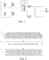
FIG. 1 is a circuit diagram of a DC-DC converter according to an embodiment of the present invention; -
FIG. 2 is a flowchart of a control method of the DC-DC converter according to the embodiments of the present invention; -
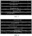
FIG. 3 is a schematic diagram of driving waveforms of four switch tubes when an H-bridge is controlled in a third mode according to an embodiment of the present invention; -
FIG. 4 is a schematic diagram of driving waveforms of four switch tubes when the H-bridge is controlled in a fourth mode according to an embodiment of the present invention; -
FIG. 5 is a flowchart of a control method of the DC-DC converter according to a specific embodiment of the present invention; and -
FIG. 6 is a block diagram of an electric vehicle according to the embodiments of the present invention. - Embodiments of the present invention are described in detail as follows. Examples of the embodiments are shown in the accompanying drawings, in which the same or similar reference signs always represent the same or similar elements or elements having the same or similar functions. The embodiments described below with reference to the accompanying drawings are exemplary, and are used for explaining rather than limiting the present invention.
- A control method of a DC-DC converter, the DC-DC converter and the electric vehicle having the DC-DC converter, provided by the embodiments of the present invention, are described below with reference to the accompanying drawings.
- As shown in
FIG. 1 , the DC-DC converter according to an embodiment of the present invention includes an H-bridge, and the H-bridge can include a first switch tube Q1, a second switch tube Q2, a third switch tube Q3 and a fourth switch tube Q4. A first node A is formed between the first switch tube Q1 and the second switch tube Q2, and a second node B is formed between the third switch tube Q3 and the fourth switch tube Q4. - Furthermore, as shown in
FIG. 1 , the DC-DC converter also includes a transformer, a first inductor LI, a first capacitor C1, a second inductor L2, a second capacitor C2, a fifth switch tube Q5 and a sixth switch tube Q6. One end of the first inductor L1 is connected with the first node A, the other end of the first inductor L1 is connected with one end of the first capacitor C1, the other end of the first capacitor C1 is connected with one end of a primary winding of the transformer, the other end of the primary winding of the transformer is connected with the second node B, a secondary winding of the transformer is respectively connected with the fifth switch tube Q5 and the sixth switch tube Q6, and the second inductor L2 and the second capacitor C2 are connected to an output end of the DC-DC converter. - In the embodiments of the present invention, as shown in
FIG. 2 , the control method of the DC-DC converter includes the following steps: - S1, when the DC-DC converter works every time, acquire total time TC for controlling the H-bridge in a third mode and total time TD for controlling the H-bridge in a fourth mode, and acquire set time Ti for controlling the H-bridge in the third mode and set time Tm for controlling the H-bridge in the fourth mode in each working cycle during a working process of the DC-DC converter.
- When the H-bridge is controlled in the third mode, the first switch tube and the third switch tube are used as upper tubes, the second switch tube and the fourth switch tube are used as lower tubes, and the first switch tube, the second switch tube, the third switch tube and the fourth switch tube are controlled by adopting a control mode of lower tube modulation. When the H-bridge is controlled in the fourth mode, the first switch tube and the third switch tube are used as lower tubes, the second switch tube and the fourth switch tube are used as upper tubes, and the first switch tube, the second switch tube, the third switch tube and the fourth switch tube are controlled by adopting a control mode of lower tube modulation.
- According to an embodiment of the present invention, when the H-bridge is controlled in the third mode, a control signal output to the first switch tube Q1 and a control signal output to the third switch tube Q3 are complementary and have a fixed duty ratio, and falling edges of control signals output to the second switch tube Q2 and the fourth switch tube Q4 are subjected to PWM control.
- Specifically, the driving waveform of the first switch tube Q1, the driving waveform of the second switch tube Q2, the driving waveform of the third switch tube Q3, a driving waveform of the fourth switch tube Q4, and the waveform of voltage UAB between two bridge arms of the H-bridge are as shown in
FIG. 3 . As can be seen fromFIG. 3 , in the four switch tubes of the H-bridge, the control signals of Q1 and Q3 are complementary and have a fixed duty ratio (50%), falling edges of Q2 and Q4 are modulated according to PWM rules, and the output voltage is adjusted by adjusting the driving voltage falling edges of the lower tubes. - Furthermore, when the H-bridge is controlled in the fourth mode, the control signal output to the second switch tube Q2 and the control signal output to the fourth switch tube Q4 are complementary and have a fixed duty ratio, and falling edges of the control signals output to the first switch tube Q1 and the third switch tube Q3 are subjected to PWM control.
- Specifically, the driving waveform of the first switch tube Q1, the driving waveform of the second switch tube Q2, the driving waveform of the third switch tube Q3, the driving waveform of the fourth switch tube Q4, and the waveform of the voltage UAB between two bridge arms of the H-bridge are as shown in
FIG. 4 . As can be seen fromFIG. 4 , in the four switch tubes of the H-bridge, the control signals of Q2 and Q4 of the H-bridge are complementary and have a fixed duty ratio (50%), falling edges of Q1 and Q3 are modulated according to PWM rules, and the output voltage is adjusted by adjusting the driving voltage falling edges of the lower tubes. - S2, judge a relation between the total time TC and the total time TD.
- S3, select the mode for controlling the H-bridge when the DC-DC converter is started according to the relation between the total time TC and the total time TD, and alternately control the H-bridge according to the set time Ti and the set time Tm, so as to perform temperature equalization control on the first switch tube, the second switch tube, the third switch tube and the fourth switch tube.
- It should be noted that, during the working process of the DC-DC converter, if the H-bridge is controlled in the third mode C only, because only a primary-side resonant inductor can be utilized in a resonant discharge stage, the switch tubes Q2 and Q4 used as lower tubes difficultly realize soft switching (namely zero voltage switching), and the switch tubes Q2 and Q4 have great switching loss and are overheated.
- Similarly, during the working process of the DC-DC converter, if the H-bridge is controlled in the fourth mode D only, because only the primary-side resonant inductor can be utilized in the resonant discharge stage, the switch tubes Q1 and Q3 used as lower tubes difficultly realize soft switching (namely zero voltage switching), and the switch tubes Q1 and Q3 have great switching loss and are overheated.
- Therefore, in the embodiments of the present invention, when the H-bridge is controlled in the third mode C to enable the DC-DC converter to work, the time for controlling the H-bridge in the third mode C is recorded to obtain the total time TC for controlling the H-bridge in the third mode, and then, the total time TC is stored; when the H-bridge is controlled in the fourth mode D to enable the DC-DC converter to work, the time for controlling the H-bridge in the fourth mode D is recorded to obtain the total time TD for controlling the H-bridge in the fourth mode, and then, the total time TD is stored; then, when the DC-DC converter is started every time, the relation between the total time TC and the total time TD is judged; and finally, the mode for controlling the H-bridge when the DC-DC converter is started is selected according to the relation between the total time TC and the total time TD.
- Specifically, according to an embodiment of the present invention, in the process of selecting the mode for controlling the H-bridge when the DC-DC converter is started according to the relation between the total time TC and the total time TD, when the total time TC is greater than the total time TD, the fourth mode is selected for controlling the H-bridge when the DC-DC converter is started until the total time TC is equal to the total time TD; when the total time TC is less than the total time TD, the third mode is selected for controlling the H-bridge when the DC-DC converter is started until the total time TC is equal to the total time TD; and when the total time TC is equal to the total time TD, the third mode or the fourth mode is selected for alternately controlling the H-bridge according to the Ti and the Tm when the DC-DC converter is started.
- Alternately controlling the H-bridge according to the set time Ti and the set time Tm includes: when the time for controlling the H-bridge in the third mode reaches the Ti, controlling the H-bridge in the fourth mode until the time for controlling the H-bridge in the fourth mode reaches the Tm; or when the time for controlling the H-bridge in the fourth mode reaches the Tm, controlling the H-bridge in the third mode until the time for controlling the H-bridge in the third mode reaches the Ti.
- In other words, before the DC-DC converter works, the total time TC for controlling the H-bridge in the third mode and the total time TD for controlling the H-bridge in the fourth mode are acquired from a storage area, the Ti and the Tm are set, then the total time TC and the total time TD are judged, and whether the H-bridge is controlled in the third mode or the fourth mode firstly is determined according to the judging result, that is, the total time TC for controlling the H-bridge in the third mode and the total time TD for controlling the H-bridge in the fourth mode are acquired from the storage area, and the relation between the total time TC and the total time TD is judged to determine the mode selected for controlling the H-bridge firstly when the DC-DC converter is started. For example, if the acquired TC is 20 minutes and the acquired TD is 18 minutes, when the DC-DC converter works currently, the fourth mode D is firstly selected to control the H-bridge to enable the DC-DC converter to start work, after 2 minutes, the mode is switched to the third mode C to control the H-bridge to enable the DC-DC converter to work until the time for controlling the H-bridge in the third mode C reaches the Ti, then the mode is switched to the fourth mode D to control the H-bridge, to enable the DC-DC converter to work until the time for controlling the H-bridge in the fourth mode D reaches the Tm, so as to complete a working cycle (time of one working cycle = Ti+Tm), then the mode is switched to the third mode C to control the H-bridge to enable the DC-DC converter to work until the time for controlling the H-bridge in the third mode C reaches the Ti, then the mode is switched to the fourth mode D to control the H-bridge to enable the DC-DC converter to work until the time for controlling the H-bridge in the fourth mode D reaches the Tm, ..., and the process is repeated to realize alternate control on the H-bridge, thereby realizing temperature equalization control on the first switch tube, the second switch tube, the third switch tube and the fourth switch tube. If the acquired TC is 18 minutes and the acquired TD is 20 minutes, when the DC-DC converter works currently, the third mode C is firstly selected to control the H-bridge to enable the DC-DC converter to start work, after 2 minutes, the mode is switched to the fourth mode D to control the H-bridge to enable the DC-DC converter to work until the time for controlling the H-bridge in the fourth mode D reaches the Tm, then the mode is switched to the third mode C to control the H-bridge to enable the DC-DC converter to work until the time for controlling the H-bridge in the third mode C reaches the Ti, so as to complete a working cycle (time of one working cycle = Ti+Tm), then the mode is switched to the fourth mode D to control the H-bridge to enable the DC-DC converter to work until the time for controlling the H-bridge in the fourth mode D reaches the Tm, then the mode is switched to the third mode C to control the H-bridge to enable the DC-DC converter to work until the time for controlling the H-bridge in the third mode C reaches the Ti, ..., and the process is repeated to realize alternate control on the H-bridge, thereby realizing temperature equalization control on the first switch tube, the second switch tube, the third switch tube and the fourth switch tube.
- Of course, when the acquired total time TC is equal to the acquired total time TD, and when the DC-DC converter is started, the third mode C can be firstly used directly for controlling the H-bridge to enable the DC-DC converter to work until the time for controlling the H-bridge in the third mode C reaches the Ti, the mode is switched to the fourth mode D to control the H-bridge to enable the DC-DC converter to work until the time for controlling the H-bridge in the fourth mode D reaches the Tm, so as to complete a working cycle (time of one working cycle = Ti+Tm), then the mode is switched to the third mode C to control the H-bridge to enable the DC-DC converter to work until the time for controlling the H-bridge in the third mode C reaches the Ti, then the mode is switched to the fourth mode D to control the H-bridge to enable the DC-DC converter to work until the time for controlling the H-bridge in the fourth mode D reaches the Tm, ..., and the process is repeated to realize alternate control on the H-bridge, thereby realizing temperature equalization control on the first switch tube, the second switch tube, the third switch tube and the fourth switch tube. Or, when the acquired total time TC is equal to the acquired total time TD, when the DC-DC converter is started, the fourth mode D can be firstly used directly for controlling the H-bridge to enable the DC-DC converter to work until the time for controlling the H-bridge in the fourth mode D reaches the Tm, the mode is switched to the third mode C to control the H-bridge to enable the DC-DC converter to work until the time for controlling the H-bridge in the third mode C reaches the Ti, so as to complete a working cycle, and such working cycle is repeated until the DC-DC converter stops working.
- After the mode is selected in each working cycle, the H-bridge is controlled according to the fixed mode, namely the third mode or the fourth mode, and the total time is recorded when the mode is switched. For example, when the H-bridge is controlled in the third mode firstly, the total time for controlling the H-bridge in the third mode, recorded when the mode is switched, is the total time for controlling the H-bridge in the third mode, acquired from the storage area when the DC-DC converter starts working plus the time for controlling the H-bridge in the third mode, recorded in this working cycle of the DC-DC converter.
- In an embodiment of the present invention, the set time Ti for controlling the H-bridge in the third mode can be equal to the set time Tm for controlling the H-bridge in the fourth mode, thereby enabling the heat generation of the first switch tube Q1, the second switch tube Q2, the third switch tube Q3 and the fourth switch tube Q4 to be relatively balanced when the H-bridge is alternately controlled in the third mode and the fourth mode.
- Of course, it can be understood that, in other embodiments of the present invention, the set time Ti for controlling the H-bridge in the third mode can also be unequal to the set time Tm for controlling the H-bridge in the fourth mode.
- It should be noted that, in the embodiments of the present invention, the control mode of lower tube modulation is adopted for the DC-DC converter no matter whether the H-bridge is controlled in the third mode or the fourth mode. When the control mode of lower tube modulation is adopted, two switch tubes as the upper tubes are alternately turned on at a duty ratio of 50% and have no dead time, and the adjustment of the output voltage is realized by adjusting the driving voltage falling edges of two switch tubes as the lower tubes.
- Furthermore, in the control mode of lower tube modulation, the two switch tubes as the upper tubes easily realize soft switching (zero voltage switching) and are corresponding to leading bridge arms in a control mode of phase shift modulation, and the two switch tubes as the lower tubes are corresponding to lagging bridge arms in the control mode of phase shift modulation and difficultly realize zero voltage switching.
- According to the embodiments of the present invention, in the starting process of the DC-DC converter during the whole life cycle, the first switch tube, the second switch tube, the third switch tube and the fourth switch tube are alternately used as the upper tubes and the lower tubes, that is, Q1 and Q3 as well as Q2 and Q4 are alternately used as the upper tubes and the lower tubes, and then, temperature stress is equivalently distributed evenly in the four switch tubes of the H-bridge, so as to enable the heat generation of each switch tube to be relatively balanced, thereby realizing overall heat balance and prolonging the service life of the DC-DC converter.
- Specifically, according to an embodiment of the present invention, as shown in
FIG. 5 , the control method of the DC-DC converter includes the following steps: - S501, begin working, namely the DC-DC converter begins to start work.
- S502, read the total time TC for controlling the H-bridge in the third mode C and the total time TD for controlling the H-bridge in the fourth mode D.
- S503, set Ti and Tm.
- S504, judge whether the TC is greater than the TD or not. If the TC is greater than the TD, execute S505; and if the TC is not greater than the TD, execute the step S506.
- S505, control the H-bridge in the fourth mode D until the TC is equal to the TD, and then, execute the step S508.
- S506, judge whether the TC is less than the TD or not. If the TC is less than the TD, execute the step S507; and if the TC is not less than the TD, execute the step S508.
- S507, select the third mode C to control the H-bridge until the TC is equal to the TD, and then, execute the step S509.
- S508, control the H-bridge in the third mode C to enable the DC-DC converter to work, and execute the step S512.
- S509, control the H-bridge in the fourth mode D to enable the DC-DC converter to work, and execute S513.
- S510, judge whether the time for controlling the H-bridge in the third mode C reaches the Ti or not. If the time for controlling the H-bridge in the third mode C reaches the Ti, execute the step S509; and if the time for controlling the H-bridge in the third mode C does not reach the Ti, return to the step S508.
- S511, judge whether the time for controlling the H-bridge in the fourth mode D reaches the Tm or not; if the time for controlling the H-bridge in the fourth mode D reaches the Tm, execute the step S508; and if the time for controlling the H-bridge in the fourth mode D does not reach the Tm, return to the step S509.
- S512, judge whether a control instruction for controlling the H-bridge to stop working is received or not. If the control instruction is not received, executing the S510; and if the control instruction is received, enter the step S514.
- S513, judging whether a control instruction for controlling the H-bridge to stop working is received or not; if the control instruction is not received, execute S511; and if the control instruction is received, enter the step S514.
- S514, the H-bridge stops working, and record the updated total time TC and the updated total time TD.
- In the step S506, if the judging result is that the TC is equal to the TD, the step S509 can be firstly executed and then the step S508 is executed, that is, the execution order of the step S509 and the step S508 can be exchanged.
- In conclusion, the control method of the DC-DC converter according to the embodiments of the present invention can enable the heat generation of the first switch tube, the second switch tube, the third switch tube and the fourth switch tube to be relatively balanced in each working process of the DC-DC converter, and additional components are not needed, thereby lowering the cost and prolonging the working life of the DC-DC converter.
- The control method of the DC-DC converter according to the embodiments of the present invention includes the following steps: when the DC-DC converter works every time, acquiring the total time TC for controlling the H-bridge in the third mode and the total time TD for controlling the H-bridge in the fourth mode, acquiring the set time Ti for controlling the H-bridge in the third mode and the set time Tm for controlling the H-bridge in the fourth mode in each working cycle during the working process of the DC-DC converter, then judging the relation between the total time TC and the total time TD, finally selecting the mode for controlling the H-bridge when the DC-DC converter is started according to the relation between the total time TC and the total time TD, and alternately controlling the H-bridge according to the Ti and the Tm during the working process of the DC-DC converter, so as to perform temperature equalization control on the first switch tube, the second switch tube, the third switch tube and the fourth switch tube, thereby enabling the heat generation of each switch tube to be relatively balanced, prolonging the working life of the switch tubes in the H-bridge without increasing the cost, and further prolonging the life cycle of the DC-DC converter.
- As shown in
FIG. 1 , the DC-DC converter according to the embodiments of the present invention includes an H-bridge and acontrol module 100 such as a micro control unit (MCU). The H-bridge includes a first switch tube Q1, a second switch tube Q2, a third switch tube Q3 and a fourth switch tube Q4, a first node A is formed between the first switch tube Q1 and the second switch tube Q2, and a second node B is formed between the third switch tube Q3 and the fourth switch tube Q4. Thecontrol module 100 is used for acquiring total time TC for controlling the H-bridge in a third mode and total time TD for controlling the H-bridge in a fourth mode when the DC-DC converter works every time, acquiring set time Ti for controlling the H-bridge in the third mode and set time Tm for controlling the H-bridge in the fourth mode in each working cycle during a working process of the DC-DC converter, selecting the mode for controlling the H-bridge when the DC-DC converter is started by judging the relation between the total time TC and the total time TD, and alternately controlling the H-bridge according to the set time Ti and the set time Tm, so as to perform temperature equalization control on the first switch tube, the second switch tube, the third switch tube and the fourth switch tube. When the H-bridge is controlled in the third mode, the control module uses the first switch tube and the third switch tube as upper tubes, uses the second switch tube and the fourth switch tube as lower tubes, and controls the first switch tube, the second switch tube, the third switch tube and the fourth switch tube by adopting a control mode of lower tube modulation. When the H-bridge is controlled in the fourth mode, the control module uses the first switch tube and the third switch tube as lower tubes, uses the second switch tube and the fourth switch tube as upper tubes, and controls the first switch tube, the second switch tube, the third switch tube and the fourth switch tube by adopting a control mode of lower tube modulation. - In the embodiments of the present invention, when the
control module 100 controls the H-bridge in the third mode C to enable the DC-DC converter to work, the time for controlling the H-bridge in the third mode C is recorded to obtain the total time TC for controlling the H-bridge in the third mode, and then, the total time TC is stored; when the control module controls the H-bridge in the fourth mode D to enable the DC-DC converter to work, the time for controlling the H-bridge in the fourth mode D is recorded to obtain the total time TD for controlling the H-bridge in the fourth mode, and then, the total time TD is stored; and then, when the DC-DC converter is started every time to work, the control module judges the relation between the total time TC and the total time TD and selects the mode for controlling the H-bridge when the DC-DC converter is started according to the relation between the total time TC and the total time TD. - Specifically, according to an embodiment of the present invention, in the process that the control module selects the mode for controlling the H-bridge when the DC-DC converter is started according to the relation between the total time TC and the total time TD, when the total time TC is greater than the total time TD, the control module selects the fourth mode for controlling the H-bridge when the DC-DC converter is started until the total time TC is equal to the total time TD; when the total time TC is less than the total time TD, the control module selects the third mode for controlling the H-bridge when the DC-DC converter is started until the total time TC is equal to the total time TD; and when the total time TC is equal to the total time TD, the control module selects the third mode or the fourth mode for alternately controlling the H-bridge according to the Ti and the Tm when the DC-DC converter is started.
- Furthermore, in the process that the control module alternately controls the H-bridge according to the set time Ti and the set time Tm, when the time for controlling the H-bridge in the third mode reaches the Ti, the H-bridge is controlled in the fourth mode until the time for controlling the H-bridge in the fourth mode reaches the Tm; or when the time for controlling the H-bridge in the fourth mode reaches the Tm, the H-bridge is controlled in the third mode until the time for controlling the H-bridge in the third mode reaches the Ti.
- In other words, before the DC-DC converter works, the control module acquires the total time TC for controlling the H-bridge in the third mode and the total time TD for controlling the H-bridge in the fourth mode from a storage area, sets the Ti and the Tm, then judges the total time TC and the total time TD, determines whether the H-bridge is controlled in the third mode or the fourth mode firstly according to the judging result, acquires the total time TC for controlling the H-bridge in the third mode and the total time TD for controlling the H-bridge in the fourth mode from the storage area, and judges the relation between the total time TC and the total time TD to determine the mode firstly selected for controlling the H-bridge when the DC-DC converter is started. For example, if the acquired TC is 20 minutes and the acquired TD is 18 minutes, when the DC-DC converter works currently, the fourth mode D is firstly selected to control the H-bridge to enable the DC-DC converter to start work, after 2 minutes, the mode is switched to the third mode C to control the H-bridge to enable the DC-DC converter to work until the time for controlling the H-bridge in the third mode C reaches the Ti, then the mode is switched to the fourth mode D to control the H-bridge to enable the DC-DC converter to work until the time for controlling the H-bridge in the fourth mode D reaches the Tm, so as to complete a working cycle (time of one working cycle = Ti+Tm), then the mode is switched to the third mode C to control the H-bridge to enable the DC-DC converter to work until the time for controlling the H-bridge in the third mode C reaches the Ti, then the mode is switched to the fourth mode D to control the H-bridge to enable the DC-DC converter to work until the time for controlling the H-bridge in the fourth mode D reaches the Tm, ..., and the process is repeated to realize alternate control on the H-bridge, thereby realizing temperature equalization control on the first switch tube, the second switch tube, the third switch tube and the fourth switch tube. If the acquired TC is 18 minutes and the acquired TD is 20 minutes, when the DC-DC converter works currently, the third mode C is firstly selected to control the H-bridge to enable the DC-DC converter to start work, after 2 minutes, the mode is switched to the fourth mode D to control the H-bridge to enable the DC-DC converter to work until the time for controlling the H-bridge in the fourth mode D reaches the Tm, then the mode is switched to the third mode C to control the H-bridge to enable the DC-DC converter to work until the time for controlling the H-bridge in the third mode C reaches the Ti, so as to complete a working cycle (time of one working cycle = Ti+Tm), then the mode is switched to the fourth mode D to control the H-bridge to enable the DC-DC converter to work until the time for controlling the H-bridge in the fourth mode D reaches the Tm, then the mode is switched to the third mode C to control the H-bridge to enable the DC-DC converter to work until the time for controlling the H-bridge in the third mode C reaches the Ti, ..., and the process is repeated to realize alternate control on the H-bridge, thereby realizing temperature equalization control on the first switch tube, the second switch tube, the third switch tube and the fourth switch tube.
- Of course, when the acquired total time TC is equal to the acquired total time TD, and when the DC-DC converter is started, the third mode C can be firstly used directly for controlling the H-bridge to enable the DC-DC converter to work until the time for controlling the H-bridge in the third mode C reaches the Ti, the mode is switched to the fourth mode D to control the H-bridge to enable the DC-DC converter to work until the time for controlling the H-bridge in the fourth mode D reaches the Tm, so as to complete a working cycle (time of one working cycle = Ti+Tm), then the mode is switched to the third mode C to control the H-bridge to enable the DC-DC converter to work until the time for controlling the H-bridge in the third mode C reaches the Ti, then the mode is switched to the fourth mode D to control the H-bridge to enable the DC-DC converter to work until the time for controlling the H-bridge in the fourth mode D reaches the Tm, ..., and the process is repeated to realize alternate control on the H-bridge, thereby realizing temperature equalization control on the first switch tube, the second switch tube, the third switch tube and the fourth switch tube. Or, when the acquired total time TC is equal to the acquired total time TD, and when the DC-DC converter is started, the fourth mode D can be firstly used directly for controlling the H-bridge to enable the DC-DC converter to work until the time for controlling the H-bridge in the fourth mode D reaches the Tm, the mode is switched to the third mode C to control the H-bridge to enable the DC-DC converter to work until the time for controlling the H-bridge in the third mode C reaches the Ti, so as to complete a working cycle, and such working cycle is repeated until the DC-DC converter stops working.
- After the mode is selected in each working cycle, the H-bridge is controlled according to the fixed mode, namely the third mode or the fourth mode, and the total time is recorded when the mode is switched. For example, when the H-bridge is controlled in the third mode firstly, the total time for controlling the H-bridge in the third mode, recorded when the mode is switched, is the total time for controlling the H-bridge in the third mode, acquired from the storage area when the DC-DC converter begins working currently plus the time for controlling the H-bridge in the third mode recorded in the current working cycle of the DC-DC converter.
- According to an embodiment of the present invention, when the H-bridge is controlled in the third mode, the control signal output to the first switch tube by the control module and the control signal output to the third switch tube by the control module are complementary and have a fixed duty ratio, and falling edges of the control signals output to the second switch tube and the fourth switch tube are subjected to PWM control.
- Furthermore, when the H-bridge is controlled in the fourth mode, the control signal output to the second switch tube by the control module and the control signal output to the fourth switch tube by the control module are complementary and have a fixed duty ratio, and falling edges of the control signals output to the first switch tube and the third switch tube are subjected to PWM control.
- In the embodiments of the present invention, as shown in
FIG. 1 , each of the first switch tube Q1, the second switch tube Q2, the third switch tube Q3 and the fourth switch tube Q4 is an insulated gate bipolar transistor (IGBT). Of course, in other embodiments of the present invention, each of the first switch tube Q1, the second switch tube Q2, the third switch tube Q3 and the fourth switch tube Q4 can be a metal oxide semiconductor (MOS) transistor. - Preferably, according to an embodiment of the present invention, the set time Ti for controlling the H-bridge in the third mode can be equal to the set time Tm for controlling the H-bridge in the fourth mode, thereby enabling the heat generation of the first switch tube Q1, the second switch tube Q2, the third switch tube Q3 and the fourth switch tube Q4 to be relatively balanced when the H-bridge is alternately controlled in the third mode and the fourth mode.
- Of course, it can be understood that, in other embodiments of the present invention, the set time Ti for controlling the H-bridge in the third mode can also be unequal to the set time Tm for controlling the H-bridge in the fourth mode.
- When the DC-DC converter according to the embodiments of the present invention works every time, the control module is used for acquiring the total time TC for controlling the H-bridge in the third mode and the total time TD for controlling the H-bridge in the fourth mode, acquiring the set time Ti for controlling the H-bridge in the third mode and the set time Tm for controlling the H-bridge in the fourth mode in each working cycle during the working process, selecting the mode for controlling the H-bridge when the DC-DC converter is started by judging the relation between the total time TC and the total time TD, and alternately controlling the H-bridge according to the Ti and the Tm during the working process of the DC-DC converter, so as to perform temperature equalization control on the first switch tube, the second switch tube, the third switch tube and the fourth switch tube, thereby enabling the heat generation of each switch tube to be relatively balanced, prolonging the working life of the switch tubes in the H-bridge without increasing the cost, and further prolonging the life cycle.
- Furthermore, as shown in
FIG. 6 , an embodiment of the present invention also provides anelectric vehicle 10, including the DC-DC converter 20. - When the DC-DC converter of the electric vehicle according to the embodiments of the present invention works every time, the temperature equalization control on the first switch tube, the second switch tube, the third switch tube and the fourth switch tube in the H-bridge can be realized, thereby enabling the heat generation of each switch tube to be relatively balanced, prolonging the working life of the switch tubes in the H-bridge without increasing the cost, and further prolonging the life cycle of the DC-DC converter.
- The above descriptions are merely preferred embodiments of the present invention, and are not intended to limit the present invention in any form. Although the present invention has been disclosed above through the preferred embodiments, the embodiments are not intended to limit the present invention. Those skilled in the art can make some equivalent variations, alterations or modifications to the above-disclosed technical content without departing from the scope of the technical solutions of the present invention to obtain equivalent embodiments. Any simple alteration, equivalent change or modification made to the above embodiments according to the technical essence of the present invention without departing from the content of the technical solutions of the present invention shall fall within the scope of the technical solutions of the present invention.
Claims (11)
- A control method of a DC-DC converter, wherein the DC-DC converter comprises an H-bridge, the H-bridge comprises a first switch tube, a second switch tube, a third switch tube and a fourth switch tube, and the control method comprises the following steps:when the DC-DC converter works, acquiring total time TC for controlling the H-bridge in a third mode and total time TD for controlling the H-bridge in a fourth mode, and acquiring set time Ti for controlling the H-bridge in the third mode and set time Tm for controlling the H-bridge in the fourth mode in each working cycle during a working process of the DC-DC converter, wherein when the H-bridge is controlled in the third mode, the first switch tube and the third switch tube are used as upper tubes, the second switch tube and the fourth switch tube are used as lower tubes, and the first switch tube, the second switch tube, the third switch tube and the fourth switch tube are controlled by adopting a control mode of lower tube modulation, and when the H-bridge is controlled in the fourth mode, the first switch tube and the third switch tube are used as lower tubes, the second switch tube and the fourth switch tube are used as upper tubes, and the first switch tube, the second switch tube, the third switch tube and the fourth switch tube are controlled by adopting a control mode of lower tube modulation;judging a relation between the total time TC and the total time TD; andselecting the mode for controlling the H-bridge when the DC-DC converter is started according to the relation between the total time TC and the total time TD, and alternately controlling the H-bridge according to the set time Ti and the set time Tm, so as to perform temperature equalization control on the first switch tube, the second switch tube, the third switch tube and the fourth switch tube.
- The control method of the DC-DC converter according to claim 1, wherein in a process of selecting the mode for controlling the H-bridge when the DC-DC converter is started according to the relation between the total time TC and the total time TD,
when the total time TC is greater than the total time TD, the fourth mode is selected for controlling the H-bridge when the DC-DC converter is started until the total time TC is equal to the total time TD;
when the total time TC is less than the total time TD, the third mode is selected for controlling the H-bridge when the DC-DC converter is started until the total time TC is equal to the total time TD; and
when the total time TC is equal to the total time TD, the third mode or the fourth mode is selected for alternately controlling the H-bridge according to the Ti and the Tm when the DC-DC converter is started. - The control method of the DC-DC converter according to claim 1 or 2, wherein
when the H-bridge is controlled in the third mode, a control signal output to the first switch tube and a control signal output to the third switch tube are complementary and have a fixed duty ratio, and falling edges of control signals output to the second switch tube and the fourth switch tube are subjected to PWM control; and
when the H-bridge is controlled in the fourth mode, the control signal output to the second switch tube and the control signal output to the fourth switch tube are complementary and have a fixed duty ratio, and falling edges of the control signals output to the first switch tube and the third switch tube are subjected to PWM control. - The control method of the DC-DC converter according to claim 1 or 2, wherein alternately controlling the H-bridge according to the set time Ti and the set time Tm comprises:when the time for controlling the H-bridge in the third mode reaches the Ti, controlling the H-bridge in the fourth mode until the time for controlling the H-bridge in the fourth mode reaches the Tm; orwhen the time for controlling the H-bridge in the fourth mode reaches the Tm, controlling the H-bridge in the third mode until the time for controlling the H-bridge in the third mode reaches the Ti.
- The control method of the DC-DC converter according to any one of claims 1 to 4, wherein the set time Ti for controlling the H-bridge in the third mode is equal to the set time Tm for controlling the H-bridge in the fourth mode.
- A DC-DC converter, comprising:an H-bridge, wherein the H-bridge comprises a first switch tube, a second switch tube, a third switch tube and a fourth switch tube; anda control module, wherein the control module is used for acquiring total time TC for controlling the H-bridge in a third mode and total time TD for controlling the H-bridge in a fourth mode when the DC-DC converter works, acquiring set time Ti for controlling the H-bridge in the third mode and set time Tm for controlling the H-bridge in the fourth mode in each working cycle during a working process of the DC-DC converter, selecting the mode for controlling the H-bridge when the DC-DC converter is started by judging a relation between the total time TC and the total time TD, and alternately controlling the H-bridge according to the set time Ti and the set time Tm, so as to perform temperature equalization control on the first switch tube, the second switch tube, the third switch tube and the fourth switch tube, whereinwhen the H-bridge is controlled in the third mode, the control module uses the first switch tube and the third switch tube as upper tubes, uses the second switch tube and the fourth switch tube as lower tubes, and controls the first switch tube, the second switch tube, the third switch tube and the fourth switch tube by adopting a control mode of lower tube modulation; andwhen the H-bridge is controlled in the fourth mode, the control module uses the first switch tube and the third switch tube as lower tubes, uses the second switch tube and the fourth switch tube as upper tubes, and controls the first switch tube, the second switch tube, the third switch tube and the fourth switch tube by adopting a control mode of lower tube modulation.
- The DC-DC converter according to claim 6, wherein in a process of selecting the mode for controlling the H-bridge when the DC-DC converter is started according to the relation between the total time TC and the total time TD by the control module,
when the total time TC is greater than the total time TD, the control module selects the fourth mode for controlling the H-bridge when the DC-DC converter is started until the total time TC is equal to the total time TD;
when the total time TC is less than the total time TD, the control module selects the third mode for controlling the H-bridge when the DC-DC converter is started until the total time TC is equal to the total time TD; and
when the total time TC is equal to the total time TD, the control module selects the third mode or the fourth mode for alternately controlling the H-bridge according to the Ti and the Tm when the DC-DC converter is started. - The DC-DC converter according to claim 6 or 7, wherein
when the H-bridge is controlled in the third mode, a control signal output to the first switch tube by the control module and a control signal output to the third switch tube by the control module are complementary and have a fixed duty ratio, and falling edges of control signals output to the second switch tube and the fourth switch tube are subjected to PWM control; and
when the H-bridge is controlled in the fourth mode, the control signal output to the second switch tube by the control module and the control signal output to the fourth switch tube by the control module are complementary and have a fixed duty ratio, and falling edges of the control signals output to the first switch tube and the third switch tube are subjected to PWM control. - The DC-DC converter according to claim 6 or 7, wherein in the process of alternately controlling the H-bridge according to the set time Ti and the set time Tm by the control module,
when the time for controlling the H-bridge in the third mode reaches the Ti, the control module controls the H-bridge in the fourth mode until the time for controlling the H-bridge in the fourth mode reaches the Tm; or
when the time for controlling the H-bridge in the fourth mode reaches the Tm, the control module controls the H-bridge in the third mode until the time for controlling the H-bridge in the third mode reaches the Ti. - The DC-DC converter according to any one of claims 6 to 9, wherein the set time Ti for controlling the H-bridge in the third mode is equal to the set time Tm for controlling the H-bridge in the fourth mode.
- An electric vehicle, comprising the DC-DC converter according to any one of claims 6 to 10.
Applications Claiming Priority (2)
| Application Number | Priority Date | Filing Date | Title |
|---|---|---|---|
| CN201611109744.2A CN108155802B (en) | 2016-12-02 | 2016-12-02 | Electric vehicle and its DC-DC converter and DC-DC converter control method |
| PCT/CN2017/114234 WO2018099468A1 (en) | 2016-12-02 | 2017-12-01 | Electric vehicle, dc-dc convertor, and control method for dc-dc convertor |
Publications (3)
| Publication Number | Publication Date |
|---|---|
| EP3550709A1 true EP3550709A1 (en) | 2019-10-09 |
| EP3550709A4 EP3550709A4 (en) | 2019-12-11 |
| EP3550709B1 EP3550709B1 (en) | 2021-03-10 |
Family
ID=62241224
Family Applications (1)
| Application Number | Title | Priority Date | Filing Date |
|---|---|---|---|
| EP17875909.8A Active EP3550709B1 (en) | 2016-12-02 | 2017-12-01 | Electric vehicle, dc-dc convertor, and control method for dc-dc convertor |
Country Status (4)
| Country | Link |
|---|---|
| US (1) | US10958181B2 (en) |
| EP (1) | EP3550709B1 (en) |
| CN (1) | CN108155802B (en) |
| WO (1) | WO2018099468A1 (en) |
Families Citing this family (3)
| Publication number | Priority date | Publication date | Assignee | Title |
|---|---|---|---|---|
| CN111682598A (en) * | 2020-04-27 | 2020-09-18 | 宁波三星智能电气有限公司 | A charging module startup method of a charging pile |
| EP4102703A1 (en) * | 2021-06-09 | 2022-12-14 | Delta Electronics (Thailand) Public Co., Ltd. | Alternating asymmetrical phase-shift modulation |
| US12107507B2 (en) | 2021-09-02 | 2024-10-01 | Rivian Ip Holdings, Llc | Dual active bridge converter control with switching loss distribution |
Family Cites Families (24)
| Publication number | Priority date | Publication date | Assignee | Title |
|---|---|---|---|---|
| CN100574080C (en) | 2007-10-18 | 2009-12-23 | 西北工业大学 | Control Method of Resonant Very Soft Switching Inverter Circuit Applied to Brushless DC Motor |
| JP5286184B2 (en) | 2009-07-28 | 2013-09-11 | 株式会社日立製作所 | Power conversion control device, power conversion device, and power conversion control method |
| CN101800472A (en) | 2010-01-28 | 2010-08-11 | 中电电气(江苏)股份有限公司 | Unipolar driving circuit |
| CN102315698B (en) | 2011-08-30 | 2013-06-12 | 矽力杰半导体技术(杭州)有限公司 | Magnetic field coupling-type non-contact electric energy transmission device |
| CN102611348B (en) * | 2012-03-21 | 2014-10-01 | 福州大学 | PWM output method to solve uneven heat generation of bridge arm switches in single-phase full-bridge inverter circuit |
| TW201427246A (en) * | 2012-12-26 | 2014-07-01 | Yen-Shin Lai | Phase-shift full-bridge converter and the controlling thereof |
| CN103259443B (en) * | 2013-05-23 | 2015-02-11 | 吕莹 | Limited dual-polarity-controlled full bridge inverter |
| US9584024B2 (en) | 2013-06-24 | 2017-02-28 | Illinois Tool Works Inc. | Metal working power supply converter system and method |
| CN103441692B (en) * | 2013-07-30 | 2016-03-30 | 飞利浦(中国)投资有限公司 | Series resonant inverter and its implementation |
| US20150055374A1 (en) * | 2013-08-22 | 2015-02-26 | Fujitsu Telecom Networks Limited | Switching power supply apparatus corresponding to zero voltage switching system |
| CN203423529U (en) | 2013-09-12 | 2014-02-05 | 河北博联通讯科技有限责任公司 | Intelligent car-mounted charger for new energy automobile lithium battery |
| CN103795233B (en) * | 2014-02-21 | 2016-08-24 | 南京冠亚电源设备有限公司 | A kind of modularity inverter power control method of intelligent start/stop polling mechanism |
| CN104868765B (en) * | 2014-02-24 | 2017-10-17 | 湖南南车时代电动汽车股份有限公司 | A kind of inverter pulse duration modulation method |
| CN104600998A (en) * | 2015-02-10 | 2015-05-06 | 四川英杰电气股份有限公司 | Method for controlling uniform heating of switch device of switch power source |
| CN104898486A (en) * | 2015-05-19 | 2015-09-09 | 合肥天鹅制冷科技有限公司 | Multi-module starting control system and method |
| CN106904083B (en) * | 2015-12-18 | 2019-09-13 | 比亚迪股份有限公司 | Electric vehicle and its on-board charger and control method of on-board charger |
| CN106891737B (en) * | 2015-12-18 | 2019-03-29 | 比亚迪股份有限公司 | The control method of electric car and its onboard charger and onboard charger |
| CN106891742B (en) * | 2015-12-18 | 2019-11-05 | 比亚迪股份有限公司 | The control method of electric car and its onboard charger and onboard charger |
| CN106891751B (en) * | 2015-12-18 | 2019-07-26 | 比亚迪股份有限公司 | Electric vehicle and its on-board charger and control method of on-board charger |
| CN106891750B (en) * | 2015-12-18 | 2019-03-29 | 比亚迪股份有限公司 | The control method of electric car and its onboard charger and onboard charger |
| CN106891740B (en) * | 2015-12-18 | 2019-12-20 | 比亚迪股份有限公司 | Electric automobile, vehicle-mounted charger thereof and control method of vehicle-mounted charger |
| CN106891745B (en) * | 2015-12-18 | 2019-11-05 | 比亚迪股份有限公司 | The control method of electric car and its onboard charger and onboard charger |
| CN106891752B (en) * | 2015-12-18 | 2019-12-10 | 比亚迪股份有限公司 | electric automobile, vehicle-mounted charger thereof and control method of vehicle-mounted charger |
| CN106169873A (en) | 2016-07-21 | 2016-11-30 | 连云港杰瑞电子有限公司 | It is applicable to mixing connection in series-parallel full-bridge circuit and the control method thereof of high pressure or High-current output |
-
2016
- 2016-12-02 CN CN201611109744.2A patent/CN108155802B/en active Active
-
2017
- 2017-12-01 WO PCT/CN2017/114234 patent/WO2018099468A1/en not_active Ceased
- 2017-12-01 EP EP17875909.8A patent/EP3550709B1/en active Active
- 2017-12-01 US US16/465,944 patent/US10958181B2/en active Active
Also Published As
| Publication number | Publication date |
|---|---|
| WO2018099468A1 (en) | 2018-06-07 |
| EP3550709B1 (en) | 2021-03-10 |
| US10958181B2 (en) | 2021-03-23 |
| EP3550709A4 (en) | 2019-12-11 |
| CN108155802B (en) | 2020-03-31 |
| US20200083815A1 (en) | 2020-03-12 |
| CN108155802A (en) | 2018-06-12 |
Similar Documents
| Publication | Publication Date | Title |
|---|---|---|
| US10892687B2 (en) | Asymmetric power converter, power converters, and operating power converters | |
| CN104038069B (en) | Electric power coversion system | |
| JP5741558B2 (en) | Power converter | |
| EP3550709B1 (en) | Electric vehicle, dc-dc convertor, and control method for dc-dc convertor | |
| CN105356755A (en) | Variable turn ratio output DC-DC converter | |
| JP6459599B2 (en) | Switching power supply | |
| US12255539B2 (en) | Three-level rectification DC/DC converter | |
| CN108155806B (en) | Electric vehicle and its DC-DC converter and DC-DC converter control method | |
| CN108155797B (en) | Electric vehicle and its DC-DC converter and DC-DC converter control method | |
| CN108155807B (en) | Electric vehicle and its DC-DC converter and DC-DC converter control method | |
| CN108155794B (en) | Electric vehicle, DC-DC converter thereof and control method of DC-DC converter | |
| CN108155795B (en) | Electric vehicle, DC-DC converter thereof and control method of DC-DC converter | |
| CN119945165B (en) | Bidirectional LLC converter control method, device, and bidirectional LLC converter | |
| WO2018099467A1 (en) | Electric vehicle, dc-dc convertor, and control method for dc-dc convertor | |
| CN108155798A (en) | The control method of electric vehicle and its DC-DC converter and DC-DC converter | |
| US12614987B2 (en) | Pulse width modulation method and system | |
| CN108155808B (en) | Electric vehicle and its DC-DC converter and DC-DC converter control method | |
| CN108155804B (en) | Electric vehicle and its DC-DC converter and DC-DC converter control method | |
| CN108155805B (en) | Electric vehicle and its DC-DC converter and DC-DC converter control method | |
| CN108155809B (en) | Electric vehicle and its DC-DC converter and DC-DC converter control method | |
| CN108155803A (en) | The control method of electric vehicle and its DC-DC converter and DC-DC converter | |
| KR20250085172A (en) | Isolated DC-DC converter and its control method | |
| JP6488960B2 (en) | Bidirectional DC-DC converter | |
| CN117937945A (en) | DC/DC converter, control method, controller and storage medium | |
| JP2024029561A (en) | power converter |
Legal Events
| Date | Code | Title | Description |
|---|---|---|---|
| STAA | Information on the status of an ep patent application or granted ep patent |
Free format text: STATUS: THE INTERNATIONAL PUBLICATION HAS BEEN MADE |
|
| PUAI | Public reference made under article 153(3) epc to a published international application that has entered the european phase |
Free format text: ORIGINAL CODE: 0009012 |
|
| STAA | Information on the status of an ep patent application or granted ep patent |
Free format text: STATUS: REQUEST FOR EXAMINATION WAS MADE |
|
| 17P | Request for examination filed |
Effective date: 20190701 |
|
| AK | Designated contracting states |
Kind code of ref document: A1 Designated state(s): AL AT BE BG CH CY CZ DE DK EE ES FI FR GB GR HR HU IE IS IT LI LT LU LV MC MK MT NL NO PL PT RO RS SE SI SK SM TR |
|
| AX | Request for extension of the european patent |
Extension state: BA ME |
|
| A4 | Supplementary search report drawn up and despatched |
Effective date: 20191108 |
|
| RIC1 | Information provided on ipc code assigned before grant |
Ipc: H02M 3/337 20060101AFI20191104BHEP Ipc: H02M 1/32 20070101ALN20191104BHEP Ipc: H02M 7/5395 20060101ALN20191104BHEP Ipc: H02M 1/36 20070101ALN20191104BHEP Ipc: H02M 3/335 20060101ALN20191104BHEP |
|
| DAV | Request for validation of the european patent (deleted) | ||
| DAX | Request for extension of the european patent (deleted) | ||
| REG | Reference to a national code |
Ref country code: DE Ref legal event code: R079 Ref document number: 602017034550 Country of ref document: DE Free format text: PREVIOUS MAIN CLASS: H02M0003335000 Ipc: H02M0003337000 |
|
| RIC1 | Information provided on ipc code assigned before grant |
Ipc: H02M 3/337 20060101AFI20200818BHEP Ipc: H02M 3/335 20060101ALN20200818BHEP Ipc: H02M 1/32 20070101ALN20200818BHEP Ipc: H02M 7/5395 20060101ALN20200818BHEP Ipc: H02M 1/36 20070101ALN20200818BHEP |
|
| GRAP | Despatch of communication of intention to grant a patent |
Free format text: ORIGINAL CODE: EPIDOSNIGR1 |
|
| STAA | Information on the status of an ep patent application or granted ep patent |
Free format text: STATUS: GRANT OF PATENT IS INTENDED |
|
| RIC1 | Information provided on ipc code assigned before grant |
Ipc: H02M 7/5395 20060101ALN20200828BHEP Ipc: H02M 3/337 20060101AFI20200828BHEP Ipc: H02M 1/32 20070101ALN20200828BHEP Ipc: H02M 1/36 20070101ALN20200828BHEP Ipc: H02M 3/335 20060101ALN20200828BHEP |
|
| INTG | Intention to grant announced |
Effective date: 20200928 |
|
| GRAS | Grant fee paid |
Free format text: ORIGINAL CODE: EPIDOSNIGR3 |
|
| GRAA | (expected) grant |
Free format text: ORIGINAL CODE: 0009210 |
|
| STAA | Information on the status of an ep patent application or granted ep patent |
Free format text: STATUS: THE PATENT HAS BEEN GRANTED |
|
| AK | Designated contracting states |
Kind code of ref document: B1 Designated state(s): AL AT BE BG CH CY CZ DE DK EE ES FI FR GB GR HR HU IE IS IT LI LT LU LV MC MK MT NL NO PL PT RO RS SE SI SK SM TR |
|
| REG | Reference to a national code |
Ref country code: GB Ref legal event code: FG4D |
|
| REG | Reference to a national code |
Ref country code: CH Ref legal event code: EP Ref country code: AT Ref legal event code: REF Ref document number: 1370929 Country of ref document: AT Kind code of ref document: T Effective date: 20210315 |
|
| REG | Reference to a national code |
Ref country code: DE Ref legal event code: R096 Ref document number: 602017034550 Country of ref document: DE |
|
| REG | Reference to a national code |
Ref country code: IE Ref legal event code: FG4D |
|
| REG | Reference to a national code |
Ref country code: NL Ref legal event code: FP |
|
| REG | Reference to a national code |
Ref country code: LT Ref legal event code: MG9D |
|
| PG25 | Lapsed in a contracting state [announced via postgrant information from national office to epo] |
Ref country code: LT Free format text: LAPSE BECAUSE OF FAILURE TO SUBMIT A TRANSLATION OF THE DESCRIPTION OR TO PAY THE FEE WITHIN THE PRESCRIBED TIME-LIMIT Effective date: 20210310 Ref country code: BG Free format text: LAPSE BECAUSE OF FAILURE TO SUBMIT A TRANSLATION OF THE DESCRIPTION OR TO PAY THE FEE WITHIN THE PRESCRIBED TIME-LIMIT Effective date: 20210610 Ref country code: NO Free format text: LAPSE BECAUSE OF FAILURE TO SUBMIT A TRANSLATION OF THE DESCRIPTION OR TO PAY THE FEE WITHIN THE PRESCRIBED TIME-LIMIT Effective date: 20210610 Ref country code: HR Free format text: LAPSE BECAUSE OF FAILURE TO SUBMIT A TRANSLATION OF THE DESCRIPTION OR TO PAY THE FEE WITHIN THE PRESCRIBED TIME-LIMIT Effective date: 20210310 Ref country code: GR Free format text: LAPSE BECAUSE OF FAILURE TO SUBMIT A TRANSLATION OF THE DESCRIPTION OR TO PAY THE FEE WITHIN THE PRESCRIBED TIME-LIMIT Effective date: 20210611 Ref country code: FI Free format text: LAPSE BECAUSE OF FAILURE TO SUBMIT A TRANSLATION OF THE DESCRIPTION OR TO PAY THE FEE WITHIN THE PRESCRIBED TIME-LIMIT Effective date: 20210310 |
|
| REG | Reference to a national code |
Ref country code: AT Ref legal event code: MK05 Ref document number: 1370929 Country of ref document: AT Kind code of ref document: T Effective date: 20210310 |
|
| PG25 | Lapsed in a contracting state [announced via postgrant information from national office to epo] |
Ref country code: LV Free format text: LAPSE BECAUSE OF FAILURE TO SUBMIT A TRANSLATION OF THE DESCRIPTION OR TO PAY THE FEE WITHIN THE PRESCRIBED TIME-LIMIT Effective date: 20210310 Ref country code: RS Free format text: LAPSE BECAUSE OF FAILURE TO SUBMIT A TRANSLATION OF THE DESCRIPTION OR TO PAY THE FEE WITHIN THE PRESCRIBED TIME-LIMIT Effective date: 20210310 Ref country code: SE Free format text: LAPSE BECAUSE OF FAILURE TO SUBMIT A TRANSLATION OF THE DESCRIPTION OR TO PAY THE FEE WITHIN THE PRESCRIBED TIME-LIMIT Effective date: 20210310 |
|
| PG25 | Lapsed in a contracting state [announced via postgrant information from national office to epo] |
Ref country code: AT Free format text: LAPSE BECAUSE OF FAILURE TO SUBMIT A TRANSLATION OF THE DESCRIPTION OR TO PAY THE FEE WITHIN THE PRESCRIBED TIME-LIMIT Effective date: 20210310 Ref country code: SM Free format text: LAPSE BECAUSE OF FAILURE TO SUBMIT A TRANSLATION OF THE DESCRIPTION OR TO PAY THE FEE WITHIN THE PRESCRIBED TIME-LIMIT Effective date: 20210310 Ref country code: CZ Free format text: LAPSE BECAUSE OF FAILURE TO SUBMIT A TRANSLATION OF THE DESCRIPTION OR TO PAY THE FEE WITHIN THE PRESCRIBED TIME-LIMIT Effective date: 20210310 Ref country code: EE Free format text: LAPSE BECAUSE OF FAILURE TO SUBMIT A TRANSLATION OF THE DESCRIPTION OR TO PAY THE FEE WITHIN THE PRESCRIBED TIME-LIMIT Effective date: 20210310 |
|
| PG25 | Lapsed in a contracting state [announced via postgrant information from national office to epo] |
Ref country code: SK Free format text: LAPSE BECAUSE OF FAILURE TO SUBMIT A TRANSLATION OF THE DESCRIPTION OR TO PAY THE FEE WITHIN THE PRESCRIBED TIME-LIMIT Effective date: 20210310 Ref country code: RO Free format text: LAPSE BECAUSE OF FAILURE TO SUBMIT A TRANSLATION OF THE DESCRIPTION OR TO PAY THE FEE WITHIN THE PRESCRIBED TIME-LIMIT Effective date: 20210310 Ref country code: PT Free format text: LAPSE BECAUSE OF FAILURE TO SUBMIT A TRANSLATION OF THE DESCRIPTION OR TO PAY THE FEE WITHIN THE PRESCRIBED TIME-LIMIT Effective date: 20210712 Ref country code: PL Free format text: LAPSE BECAUSE OF FAILURE TO SUBMIT A TRANSLATION OF THE DESCRIPTION OR TO PAY THE FEE WITHIN THE PRESCRIBED TIME-LIMIT Effective date: 20210310 Ref country code: IS Free format text: LAPSE BECAUSE OF FAILURE TO SUBMIT A TRANSLATION OF THE DESCRIPTION OR TO PAY THE FEE WITHIN THE PRESCRIBED TIME-LIMIT Effective date: 20210710 |
|
| REG | Reference to a national code |
Ref country code: DE Ref legal event code: R097 Ref document number: 602017034550 Country of ref document: DE |
|
| PLBE | No opposition filed within time limit |
Free format text: ORIGINAL CODE: 0009261 |
|
| STAA | Information on the status of an ep patent application or granted ep patent |
Free format text: STATUS: NO OPPOSITION FILED WITHIN TIME LIMIT |
|
| PG25 | Lapsed in a contracting state [announced via postgrant information from national office to epo] |
Ref country code: DK Free format text: LAPSE BECAUSE OF FAILURE TO SUBMIT A TRANSLATION OF THE DESCRIPTION OR TO PAY THE FEE WITHIN THE PRESCRIBED TIME-LIMIT Effective date: 20210310 Ref country code: AL Free format text: LAPSE BECAUSE OF FAILURE TO SUBMIT A TRANSLATION OF THE DESCRIPTION OR TO PAY THE FEE WITHIN THE PRESCRIBED TIME-LIMIT Effective date: 20210310 Ref country code: ES Free format text: LAPSE BECAUSE OF FAILURE TO SUBMIT A TRANSLATION OF THE DESCRIPTION OR TO PAY THE FEE WITHIN THE PRESCRIBED TIME-LIMIT Effective date: 20210310 |
|
| 26N | No opposition filed |
Effective date: 20211213 |
|
| PG25 | Lapsed in a contracting state [announced via postgrant information from national office to epo] |
Ref country code: SI Free format text: LAPSE BECAUSE OF FAILURE TO SUBMIT A TRANSLATION OF THE DESCRIPTION OR TO PAY THE FEE WITHIN THE PRESCRIBED TIME-LIMIT Effective date: 20210310 |
|
| PG25 | Lapsed in a contracting state [announced via postgrant information from national office to epo] |
Ref country code: IT Free format text: LAPSE BECAUSE OF FAILURE TO SUBMIT A TRANSLATION OF THE DESCRIPTION OR TO PAY THE FEE WITHIN THE PRESCRIBED TIME-LIMIT Effective date: 20210310 |
|
| PG25 | Lapsed in a contracting state [announced via postgrant information from national office to epo] |
Ref country code: IS Free format text: LAPSE BECAUSE OF FAILURE TO SUBMIT A TRANSLATION OF THE DESCRIPTION OR TO PAY THE FEE WITHIN THE PRESCRIBED TIME-LIMIT Effective date: 20210710 |
|
| PG25 | Lapsed in a contracting state [announced via postgrant information from national office to epo] |
Ref country code: MC Free format text: LAPSE BECAUSE OF FAILURE TO SUBMIT A TRANSLATION OF THE DESCRIPTION OR TO PAY THE FEE WITHIN THE PRESCRIBED TIME-LIMIT Effective date: 20210310 |
|
| REG | Reference to a national code |
Ref country code: CH Ref legal event code: PL |
|
| REG | Reference to a national code |
Ref country code: BE Ref legal event code: MM Effective date: 20211231 |
|
| PG25 | Lapsed in a contracting state [announced via postgrant information from national office to epo] |
Ref country code: LU Free format text: LAPSE BECAUSE OF NON-PAYMENT OF DUE FEES Effective date: 20211201 Ref country code: IE Free format text: LAPSE BECAUSE OF NON-PAYMENT OF DUE FEES Effective date: 20211201 |
|
| PG25 | Lapsed in a contracting state [announced via postgrant information from national office to epo] |
Ref country code: BE Free format text: LAPSE BECAUSE OF NON-PAYMENT OF DUE FEES Effective date: 20211231 |
|
| PG25 | Lapsed in a contracting state [announced via postgrant information from national office to epo] |
Ref country code: LI Free format text: LAPSE BECAUSE OF NON-PAYMENT OF DUE FEES Effective date: 20211231 Ref country code: CH Free format text: LAPSE BECAUSE OF NON-PAYMENT OF DUE FEES Effective date: 20211231 |
|
| PG25 | Lapsed in a contracting state [announced via postgrant information from national office to epo] |
Ref country code: CY Free format text: LAPSE BECAUSE OF FAILURE TO SUBMIT A TRANSLATION OF THE DESCRIPTION OR TO PAY THE FEE WITHIN THE PRESCRIBED TIME-LIMIT Effective date: 20210310 |
|
| P01 | Opt-out of the competence of the unified patent court (upc) registered |
Effective date: 20230527 |
|
| PG25 | Lapsed in a contracting state [announced via postgrant information from national office to epo] |
Ref country code: HU Free format text: LAPSE BECAUSE OF FAILURE TO SUBMIT A TRANSLATION OF THE DESCRIPTION OR TO PAY THE FEE WITHIN THE PRESCRIBED TIME-LIMIT; INVALID AB INITIO Effective date: 20171201 |
|
| PG25 | Lapsed in a contracting state [announced via postgrant information from national office to epo] |
Ref country code: MK Free format text: LAPSE BECAUSE OF FAILURE TO SUBMIT A TRANSLATION OF THE DESCRIPTION OR TO PAY THE FEE WITHIN THE PRESCRIBED TIME-LIMIT Effective date: 20210310 |
|
| PG25 | Lapsed in a contracting state [announced via postgrant information from national office to epo] |
Ref country code: MT Free format text: LAPSE BECAUSE OF FAILURE TO SUBMIT A TRANSLATION OF THE DESCRIPTION OR TO PAY THE FEE WITHIN THE PRESCRIBED TIME-LIMIT Effective date: 20210310 |
|
| PG25 | Lapsed in a contracting state [announced via postgrant information from national office to epo] |
Ref country code: TR Free format text: LAPSE BECAUSE OF FAILURE TO SUBMIT A TRANSLATION OF THE DESCRIPTION OR TO PAY THE FEE WITHIN THE PRESCRIBED TIME-LIMIT Effective date: 20210310 |
|
| PGFP | Annual fee paid to national office [announced via postgrant information from national office to epo] |
Ref country code: GB Payment date: 20251218 Year of fee payment: 9 |
|
| PGFP | Annual fee paid to national office [announced via postgrant information from national office to epo] |
Ref country code: NL Payment date: 20251219 Year of fee payment: 9 Ref country code: FR Payment date: 20251217 Year of fee payment: 9 |
|
| PGFP | Annual fee paid to national office [announced via postgrant information from national office to epo] |
Ref country code: DE Payment date: 20251222 Year of fee payment: 9 |