EP3550690B1 - Elektrisches stromsystem mit mehreren energiespeichermodulen - Google Patents
Elektrisches stromsystem mit mehreren energiespeichermodulen Download PDFInfo
- Publication number
- EP3550690B1 EP3550690B1 EP19166846.6A EP19166846A EP3550690B1 EP 3550690 B1 EP3550690 B1 EP 3550690B1 EP 19166846 A EP19166846 A EP 19166846A EP 3550690 B1 EP3550690 B1 EP 3550690B1
- Authority
- EP
- European Patent Office
- Prior art keywords
- bus
- esms
- voltage
- esm
- energy storage
- Prior art date
- Legal status (The legal status is an assumption and is not a legal conclusion. Google has not performed a legal analysis and makes no representation as to the accuracy of the status listed.)
- Active
Links
Images



Classifications
-
- H—ELECTRICITY
- H02—GENERATION; CONVERSION OR DISTRIBUTION OF ELECTRIC POWER
- H02J—ELECTRIC POWER NETWORKS; CIRCUIT ARRANGEMENTS OR SYSTEMS FOR SUPPLYING OR DISTRIBUTING ELECTRIC POWER; SYSTEMS FOR STORING ELECTRIC ENERGY
- H02J1/00—Circuit arrangements for DC mains or DC distribution networks
- H02J1/08—Three-wire DC power distribution systems; Systems having more than three wires
-
- G—PHYSICS
- G05—CONTROLLING; REGULATING
- G05B—CONTROL OR REGULATING SYSTEMS IN GENERAL; FUNCTIONAL ELEMENTS OF SUCH SYSTEMS; MONITORING OR TESTING ARRANGEMENTS FOR SUCH SYSTEMS OR ELEMENTS
- G05B15/00—Systems controlled by a computer
- G05B15/02—Systems controlled by a computer electric
-
- G—PHYSICS
- G05—CONTROLLING; REGULATING
- G05F—SYSTEMS FOR REGULATING ELECTRIC OR MAGNETIC VARIABLES
- G05F1/00—Automatic systems in which deviations of an electric quantity from one or more predetermined values are detected at the output of the system and fed back to a device within the system to restore the detected quantity to its predetermined value or values, i.e. retroactive systems
- G05F1/66—Regulating electric power
-
- G—PHYSICS
- G06—COMPUTING OR CALCULATING; COUNTING
- G06F—ELECTRIC DIGITAL DATA PROCESSING
- G06F1/00—Details not covered by groups G06F3/00 - G06F13/00 and G06F21/00
- G06F1/26—Power supply means, e.g. regulation thereof
- G06F1/263—Arrangements for using multiple switchable power supplies, e.g. battery and AC
-
- H—ELECTRICITY
- H02—GENERATION; CONVERSION OR DISTRIBUTION OF ELECTRIC POWER
- H02J—ELECTRIC POWER NETWORKS; CIRCUIT ARRANGEMENTS OR SYSTEMS FOR SUPPLYING OR DISTRIBUTING ELECTRIC POWER; SYSTEMS FOR STORING ELECTRIC ENERGY
- H02J1/00—Circuit arrangements for DC mains or DC distribution networks
- H02J1/10—Parallel operation of DC sources
-
- H—ELECTRICITY
- H02—GENERATION; CONVERSION OR DISTRIBUTION OF ELECTRIC POWER
- H02J—ELECTRIC POWER NETWORKS; CIRCUIT ARRANGEMENTS OR SYSTEMS FOR SUPPLYING OR DISTRIBUTING ELECTRIC POWER; SYSTEMS FOR STORING ELECTRIC ENERGY
- H02J1/00—Circuit arrangements for DC mains or DC distribution networks
- H02J1/10—Parallel operation of DC sources
- H02J1/102—Parallel operation of DC sources being switching converters
-
- H—ELECTRICITY
- H02—GENERATION; CONVERSION OR DISTRIBUTION OF ELECTRIC POWER
- H02J—ELECTRIC POWER NETWORKS; CIRCUIT ARRANGEMENTS OR SYSTEMS FOR SUPPLYING OR DISTRIBUTING ELECTRIC POWER; SYSTEMS FOR STORING ELECTRIC ENERGY
- H02J7/00—Circuit arrangements for charging or discharging batteries or for supplying loads from batteries
- H02J7/34—Parallel operation in networks using both storage and other DC sources, e.g. providing buffering
- H02J7/345—Parallel operation in networks using both storage and other DC sources, e.g. providing buffering using capacitors as storage or buffering devices
-
- H—ELECTRICITY
- H02—GENERATION; CONVERSION OR DISTRIBUTION OF ELECTRIC POWER
- H02J—ELECTRIC POWER NETWORKS; CIRCUIT ARRANGEMENTS OR SYSTEMS FOR SUPPLYING OR DISTRIBUTING ELECTRIC POWER; SYSTEMS FOR STORING ELECTRIC ENERGY
- H02J7/00—Circuit arrangements for charging or discharging batteries or for supplying loads from batteries
- H02J7/50—Circuit arrangements for charging or discharging batteries or for supplying loads from batteries acting upon multiple batteries simultaneously or sequentially
- H02J7/52—Circuit arrangements for charging or discharging batteries or for supplying loads from batteries acting upon multiple batteries simultaneously or sequentially for charge balancing, e.g. equalisation of charge between batteries
- H02J7/56—Active balancing, e.g. using capacitor-based, inductor-based or DC-DC converters
-
- H—ELECTRICITY
- H02—GENERATION; CONVERSION OR DISTRIBUTION OF ELECTRIC POWER
- H02M—APPARATUS FOR CONVERSION BETWEEN AC AND AC, BETWEEN AC AND DC, OR BETWEEN DC AND DC, AND FOR USE WITH MAINS OR SIMILAR POWER SUPPLY SYSTEMS; CONVERSION OF DC OR AC INPUT POWER INTO SURGE OUTPUT POWER; CONTROL OR REGULATION THEREOF
- H02M3/00—Conversion of DC power input into DC power output
- H02M3/02—Conversion of DC power input into DC power output without intermediate conversion into AC
- H02M3/04—Conversion of DC power input into DC power output without intermediate conversion into AC by static converters
- H02M3/10—Conversion of DC power input into DC power output without intermediate conversion into AC by static converters using discharge tubes with control electrode or semiconductor devices with control electrode
- H02M3/145—Conversion of DC power input into DC power output without intermediate conversion into AC by static converters using discharge tubes with control electrode or semiconductor devices with control electrode using devices of a triode or transistor type requiring continuous application of a control signal
- H02M3/155—Conversion of DC power input into DC power output without intermediate conversion into AC by static converters using discharge tubes with control electrode or semiconductor devices with control electrode using devices of a triode or transistor type requiring continuous application of a control signal using semiconductor devices only
-
- H—ELECTRICITY
- H02—GENERATION; CONVERSION OR DISTRIBUTION OF ELECTRIC POWER
- H02M—APPARATUS FOR CONVERSION BETWEEN AC AND AC, BETWEEN AC AND DC, OR BETWEEN DC AND DC, AND FOR USE WITH MAINS OR SIMILAR POWER SUPPLY SYSTEMS; CONVERSION OF DC OR AC INPUT POWER INTO SURGE OUTPUT POWER; CONTROL OR REGULATION THEREOF
- H02M3/00—Conversion of DC power input into DC power output
- H02M3/02—Conversion of DC power input into DC power output without intermediate conversion into AC
- H02M3/04—Conversion of DC power input into DC power output without intermediate conversion into AC by static converters
- H02M3/10—Conversion of DC power input into DC power output without intermediate conversion into AC by static converters using discharge tubes with control electrode or semiconductor devices with control electrode
- H02M3/145—Conversion of DC power input into DC power output without intermediate conversion into AC by static converters using discharge tubes with control electrode or semiconductor devices with control electrode using devices of a triode or transistor type requiring continuous application of a control signal
- H02M3/155—Conversion of DC power input into DC power output without intermediate conversion into AC by static converters using discharge tubes with control electrode or semiconductor devices with control electrode using devices of a triode or transistor type requiring continuous application of a control signal using semiconductor devices only
- H02M3/156—Conversion of DC power input into DC power output without intermediate conversion into AC by static converters using discharge tubes with control electrode or semiconductor devices with control electrode using devices of a triode or transistor type requiring continuous application of a control signal using semiconductor devices only with automatic control of output voltage or current, e.g. switching regulators
- H02M3/158—Conversion of DC power input into DC power output without intermediate conversion into AC by static converters using discharge tubes with control electrode or semiconductor devices with control electrode using devices of a triode or transistor type requiring continuous application of a control signal using semiconductor devices only with automatic control of output voltage or current, e.g. switching regulators including plural semiconductor devices as final control devices for a single load
- H02M3/1582—Buck-boost converters
-
- Y—GENERAL TAGGING OF NEW TECHNOLOGICAL DEVELOPMENTS; GENERAL TAGGING OF CROSS-SECTIONAL TECHNOLOGIES SPANNING OVER SEVERAL SECTIONS OF THE IPC; TECHNICAL SUBJECTS COVERED BY FORMER USPC CROSS-REFERENCE ART COLLECTIONS [XRACs] AND DIGESTS
- Y02—TECHNOLOGIES OR APPLICATIONS FOR MITIGATION OR ADAPTATION AGAINST CLIMATE CHANGE
- Y02T—CLIMATE CHANGE MITIGATION TECHNOLOGIES RELATED TO TRANSPORTATION
- Y02T10/00—Road transport of goods or passengers
- Y02T10/60—Other road transportation technologies with climate change mitigation effect
- Y02T10/70—Energy storage systems for electromobility, e.g. batteries
Definitions
- the vehicle may also include pulse loads that require supplemental power, causing a spike in the overall load of the electrical system.
- pulse loads could include a radar or a directed energy weapon.
- On-board energy storage devices that charge from the generator can be used to provide supplemental power for pulse loads.
- Zheng Huiping et al.: "A Control Strategy of Hybrid Energy Storage System in Pi-Polar Type DC Micro-Grid", 2017 IEEE Conference on Energy Internet and Energy System Integration (EI2), IEEE, 26 November 2017, pages 1-6, XP033288331 describes a coordinated control strategy for a hybrid energy storage system (HESS) to stabilize DC bus voltages in a bipolar type DC grid.
- HESS hybrid energy storage system
- An example electrical power system includes a direct current (DC) bus including a positive rail configured to provide a positive DC voltage, a negative rail configured to provide a negative DC voltage, and a ground rail.
- a first energy storage module (ESM) and a second ESM are connected to the DC bus.
- Each ESM includes an energy storage device.
- the first and second ESM are connected to and configured to provide an output voltage to a respective one of the positive and negative rail.
- a node connects the first and second ESMs to each other and to the ground rail.
- a controller is configured to determine values for the output voltages for use during at least one of a discharging mode in which the energy storage devices discharge onto the DC bus and a charging mode in which the energy storage devices charge from the DC bus based on a difference between a state of charge value of each of the first and second energy storage devices.
- An example method of operating an electrical power system includes measuring a state of charge of each of a first energy storage device of a first ESM and a second energy storage device of a second ESM.
- the first ESM is connected to and configured to provide an output voltage to a positive rail of a DC bus that is configured to provide a positive DC voltage.
- the second ESM is connected to and configured to provide an output voltage to a negative rail of the DC bus that is configured to provide a negative DC voltage.
- a node connects the first and second ESMs to each other and to a ground rail of the DC bus.
- Values are determined for the output voltages for use during at least one of a discharging mode in which the energy storage devices discharge onto the DC bus and a charging mode in which the energy storage devices charge from the DC bus based on a difference between a state of charge value of each of the first and second energy storage devices.
- FIG. 1 is a schematic view of an example aircraft 10 that includes an electrical power system 12.
- the electrical power system 12 includes a generator 14, AC/DC converter 16, and DC bus 18.
- the generator 14 converts rotational movement (e.g., of a rotor of a gas turbine engine) to electrical power.
- the AC/DC converter 16 converts an alternating current (AC) voltage from the generator 14 to a direct current (DC) voltage, and provides the DC voltage to the DC bus 18.
- AC alternating current
- DC direct current
- a baseline load 20 and one or more pulse loads 22 are powered over the DC bus 18.
- the baseline load 20 could include flight controls, sensors, and/or other electrical devices of the aircraft 10, for example.
- the pulse load 22 could include one or more of a radar device and a directed energy weapon, for example.
- the electrical power system 12 includes a plurality of energy storage modules (ESMs) 24A-B that are configured to charge from the DC bus 18 in a charging mode, and to act as supplemental power stages by providing supplemental power to the DC bus 18 in a discharging mode when the one or more pulse loads 22 are utilized.
- ESMs energy storage modules
- Each pulse load 22 needs a relatively large amount of power over a relatively short time duration, and the ESM 24 is able to meet that power demand.
- FIG. 1 only two ESMs 24A-B are shown in Figure 1 , it is understood that additional ESMs could 24 be used if desired.
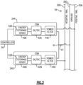
- FIG. 2 is a schematic view of an example of the power control system 12.
- the DC bus 18 is a split DC bus that includes a positive rail 30A that provides a positive voltage, a negative rail 30B that provides a negative voltage, and a ground rail 30C.
- a node N1 connects the ESMs 24A-B to each other and to the ground rail 30C.
- the ESMs 24A-B can be described as being stacked in series.
- a resistor R1 is connected between the node N1 and the ground rail 30C. The resistor R1 limits a flow of current from the node N1 to the ground rail 30C.
- the magnitude of positive voltage on positive rail 30A and the magnitude of the negative voltage on the negative rail 30B are approximately the same (e.g., on the order of 300 volts).
- the DC bus 18 can be said to provide a voltage of ⁇ 300 volts, or a "total bus voltage" of 600 volts.
- the ground rail 30C may be a neutral rail that acts as a ground.
- the ground rail 30C could connect to a chassis of the vehicle or a neutral terminal of the generator 14, for example.
- Each ESM 24 includes at least one energy storage device 40, a DC/DC converter 42, and a power filter 44.
- the energy storage devices 40 can include a variety of devices, such as batteries, fuel cells, and ultracapacitors, for example. Ultracapacitors are high-capacity capacitors that can typically store 10 - 100 times more energy per unit volume or mass than electrolytic capacitors. In one example, each ESM 24A-B includes the same type of energy storage device 40.
- Certain types of energy storage devices 40 are well-suited for certain types of pulse loads.
- ultracapacitors are well-suited for the power requirements of radar pulse loads, whereas batteries are well-suited for the energy requirements of laser pulse loads.
- the DC/DC converters 42 provide an output voltage from their respective energy storage devices 40A-B to the DC bus.
- DC/DC converter 42A provides an output voltage to positive rail 30A
- DC/DC converter 42B provides an output voltage to negative rail 30B.
- the "output voltage" of an ESM 24 refers to the output voltage of its DC/DC converter 42 to the DC bus 18.
- the DC/DC converters 42 are operable as buck/boost converters to adjust the voltage on the DC bus 18 with respect to the voltage of their respective energy storage device 40.
- the voltages of the energy storage devices 40 have a lower magnitude than that of the DC bus.
- the DC bus 18 may have a voltage of ⁇ 300 volts (i.e., approximately +300 volts on positive rail 30A and -300 volts on negative rail 30B), and each energy storage device 40 may have a voltage on the order of 150 volts.
- the DC/DC converters 42 operate in a buck mode when charging the energy storage devices 40 and operate in a boost mode when discharging the energy storage devices 40.
- the DC/DC converters 42 convert the larger magnitude DC voltage from the respective rail 30 to which the ESM 24 is connected to a lower magnitude DC voltage for charging the energy storage device 40. This is also known as "sinking" current from the DC bus 18.
- the DC/DC converters 42 convert the lower magnitude voltages of the energy storage devices 40 to the higher magnitude voltages of the respective rail 30 to which the ESM 24 is connected for discharging the energy storage devices 40 onto the DC bus. This is also known as "sourcing current" to the DC bus 18.
- Power filters 44A-B provide for electromagnetic interference (EMI) filtering when charging or discharging the energy storage devices 40.
- EMI electromagnetic interference
- a controller 50 controls an output that each DC/DC converter 42 provides to the DC bus 18 to control whether the ESMs 24 are in the discharging mode or the charging mode. If the sum of magnitude of the output voltages (e.g., 300 volts from ESM 24A and -300 volts from ESM 24B, for a "total ESM voltage" of 600 volts) is the same as the total DC bus voltage (e.g., 600 volts), the ESMs 24 will be "off” (i.e., connected to and providing a voltage to the DC bus 18, but neither charging nor discharging).
- the ESMs 24 If the sum of the magnitude of the output voltages is greater than the total DC bus 18 voltage, the ESMs 24 enter the discharging mode and will provide power to the DC bus 18 for discharging. Conversely, if the sum of the magnitude of the discharge voltages is less than the total DC bus voltage, the ESMs 24 will enter the charging mode and will draw power from the DC bus 18 for charging.
Landscapes
- Engineering & Computer Science (AREA)
- Power Engineering (AREA)
- Physics & Mathematics (AREA)
- General Physics & Mathematics (AREA)
- General Engineering & Computer Science (AREA)
- Theoretical Computer Science (AREA)
- Automation & Control Theory (AREA)
- Electromagnetism (AREA)
- Radar, Positioning & Navigation (AREA)
- Charge And Discharge Circuits For Batteries Or The Like (AREA)
- Secondary Cells (AREA)
Claims (15)
- Ein elektrisches Leistungssystem (12), dadurch gekennzeichnet, dass es umfasst:einen Gleichstrombus (DC) (18), der eine positive Schiene, die zum Bereitstellen einer positiven Gleichspannung konfiguriert ist, eine negative Schiene, die zum Bereitstellen einer negativen Gleichspannung konfiguriert ist, und eine Erdungsschiene (30C) umfasst;ein erstes Energiespeichermodul (ESM) (24A) und ein zweites ESM (24B), die mit dem Gleichstrombus (18) verbunden sind, wobei jedes ESM eine Energiespeichervorrichtung umfasst und jedes ESM mit einer jeweiligen der positiven und negativen Schienen verbunden und dazu konfiguriert ist, eine Ausgangsspannung an diese bereitzustellen, wobei ein Knoten das erste und das zweite ESM (24A,B) miteinander und mit der Erdungsschiene (30C) verbindet; undeine Steuereinheit (50), die dazu konfiguriert ist, Werte für die Ausgangsspannungen zur Verwendung während eines Entlademodus, in dem die Energiespeichervorrichtungen auf den DC-Bus (18) entladen werden, und eines Lademodus, in dem die Energiespeichervorrichtungen vom DC-Bus (18) geladen werden, basierend auf einer Differenz zwischen einem Ladezustandswert jedes der ersten und zweiten Energiespeichervorrichtungen zu bestimmen; und wobei jedes ESM (24A,B) einen DC/DC-Wandler umfasst, der seine jeweilige Energiespeichervorrichtung mit dem DC-Bus (18) verbindet, und die Ausgangsspannungen DC/DC-Wandler-Ausgangsspannungen sind.
- Elektrisches Leistungssystem nach Anspruch 1,
wobei die Steuereinheit dazu konfiguriert ist, die Ausgangsspannungen zu steuern, um die Differenz zu verringern. - Das elektrische Leistungssystem nach einem der vorhergehenden Ansprüche, wobei die Steuereinheit (50) zu Folgendem konfiguriert ist:Verwendung von Standardwerten für die Ausgangsspannungen, basierend darauf, dass die Differenz unter einem vordefinierten Schwellenwert liegt; undVerwendung angepasster Werte, die von den Standardwerten für die Ausgangsspannungen abweichen, wenn die Differenz den vordefinierten Schwellenwert überschreitet.
- Das elektrische Leistungssystem nach Anspruch 3, wobei die Steuereinheit (50) zum Verwenden der angepassten Spannungen zu Folgendem konfiguriert ist:Erhöhen der Ausgangsspannung für eines der ESM; undVerringern der Ausgangsspannung für die anderen ESM.
- Das elektrische Leistungssystem nach Anspruch 4, wobei die Steuereinheit im Entlademodus zu Folgendem konfiguriert ist:Auswahl des ESM, das einen ersten Ladezustandswert als das eine der ESM aufweist; undAuswahl des ESM, das einen zweiten Ladezustandswert aufweist, der niedriger ist als der erste Ladezustandswert des anderen ESM, und/oderwobei im Lademodus die Steuereinheit zu Folgendem konfiguriert ist:Auswahl des ESM, das einen ersten Ladezustandswert als das eine der ESM aufweist; undAuswahl des ESM, das einen zweiten Ladezustandswert aufweist, der höher ist als der erste Ladezustandswert der anderen ESM.
- Das elektrische Leistungssystem nach Anspruch 4, wobei:die Steuereinheit (50) zum Erhöhen der Ausgangsspannung für eines der ESM so konfiguriert ist, dass sie eine Spannungserhöhung für das eine der ESM schrittweise von einem aktuellen Wert auf einen erhöhten Zielwert durchführt; unddie Steuereinheit (50) zum Verringern der Ausgangsspannung für das andere der ESM so konfiguriert ist, dass sie für das andere der ESM schrittweise eine Spannungsverringerung von einem aktuellen Wert auf einen verringerten Zielwert durchführt.
- Elektrisches Leistungssystem nach Anspruch 6, wobei die Steuereinheit (50) dazu konfiguriert ist, die schrittweise Umsetzung der Spannungserhöhung vor Erreichen des erhöhten Zielwerts zu beenden und die schrittweise Umsetzung der Spannungsverringerung vor Erreichen des verringerten Zielwerts zu beenden, basierend darauf, dass die Differenz zwischen den Ladezustandswerten geringer wird als der vordefinierte Differenzschwellenwert.
- Elektrisches Leistungssystem nach Anspruch 6, umfassend:einen Generator, der dazu konfiguriert ist, die Energiespeichervorrichtungen über den DC-Bus (18) aufzuladen und einen ersten Verbraucher über den DC-Bus (18) mit Strom zu versorgen, der von den ESM getrennt ist;wobei eine Größe des erhöhten Zielwerts größer ist als eine Größe einer Spannung, die vom Generator an eine der positiven oder negativen Schienen geliefert wird; undwobei eine Größe des verringerten Zielwerts kleiner ist als eine Größe einer Spannung, die vom Generator an eine der positiven oder negativen Schienen geliefert wird.
- Elektrisches Leistungssystem nach Anspruch 6, wobei die Größe der Spannungserhöhung und der Spannungsverringerung jeweils ungefähr gleich ist.
- Elektrisches Leistungssystem nach einem der vorhergehenden Ansprüche, umfassend:einen Generator, der dazu konfiguriert ist, einen ersten Verbraucher über den DC-Bus (18) mit Strom zu versorgen, der von den ESM getrennt ist;wobei die ESM so konfiguriert sind, dass sie im Entlademodus eines zweiten Verbrauchers über den DC-Bus (18) zusätzliche Leistung bereitstellen, und der zweite Verbraucher eine Impulslast ist und sich vom ersten Verbraucher unterscheidet,
und/oderwobei die Energiespeichervorrichtung des ersten und des zweiten ESM jeweils einen Ultrakondensator oder eine Batterie umfasst. - Verfahren zum Betreiben eines elektrischen Leistungssystems, dadurch gekennzeichnet, dass es Folgendes umfasst:Messen eines Ladezustands einer ersten Energiespeichervorrichtung eines ersten Energiespeichermoduls (ESM) (24A) und einer zweiten Energiespeichervorrichtung eines zweiten ESM (24B), wobei das erste ESM (24A) einen DC/DC-Wandler umfasst, der mit einem DC-Bus verbunden ist und dazu konfiguriert ist, eine Ausgangsspannung an eine positive Schiene des DC-Busses (18) bereitzustellen, wobei das zweite ESM (24B) einen DC/DC-Wandler umfasst, der mit dem DC-Bus verbunden ist und dazu konfiguriert ist, eine Ausgangsspannung an eine negative Schiene des DC-Busses bereitzustellen, wobei die positive Schiene dazu konfiguriert ist, eine positive Gleichspannung bereitzustellen, die negative Schiene dazu konfiguriert ist, eine negative Gleichspannung bereitzustellen, und ein Knoten, der das erste und das zweite ESM miteinander und mit einer Erdungsschiene des DC-Busses verbindet; undBestimmen und Steuern von Werten für die Ausgangsspannungen während eines Entlademodus, in dem die Energiespeichervorrichtungen auf den DC-Bus (18) entladen werden, und eines Lademodus, in dem die Energiespeichervorrichtungen vom DC-Bus (18) geladen werden, wobei das Bestimmen auf einer Differenz zwischen einem Ladezustandswert jedes der ersten und zweiten Energiespeichervorrichtungen basiert.
- Verfahren nach Anspruch 11, wobei das genannte Bestimmen Folgendes umfasst:Bestimmen von Standardwerten für die Ausgangsspannungen, basierend darauf, dass die Differenz unter einem vordefinierten Schwellenwert liegt; undBestimmen angepasster Werte, die von den Standardwerten für die Ausgangsspannungen abweichen, wenn die Differenz den vordefinierten Schwellenwert überschreitet, und/oder umfassend:Versorgen eines ersten Verbrauchers über den DC-Bus (18) von einem Generator aus mit Energie, wobei der erste Verbraucher von den ESM getrennt ist; undVersorgen eines zweiten Verbrauchers über den DC-Bus (18) im Entlademodus mit Energie, wobei der zweite Verbraucher eine Impulslast ist und sich vom ersten Verbraucher unterscheidet.
- Verfahren nach Anspruch 11 oder 12, umfassend:
Steuern eines DC/DC-Wandlers jedes ESM, der die Energiespeichervorrichtung des ESM mit dem DC-Bus verbindet, um eine jeweilige der Ausgangsspannungen zum Laden der zugehörigen Energiespeichervorrichtung vom DC-Bus im Lademodus oder zum Entladen der zugehörigen Energiespeichervorrichtung auf den DC-Bus im Entlademodus zu verwenden. - Verfahren nach Anspruch 13, wobei durch die Steuerung die Differenz verringert wird.
- Das Verfahren nach Anspruch 13, wobei im Entlademodus die Steuerung Folgendes umfasst:Erhöhen der Ausgangsspannung für eines der ESM, das einen ersten Ladezustandswert aufweist; undVerringern der Ausgangsspannung für das andere der ESM, das einen zweiten Ladezustandswert aufweist, der niedriger ist als der erste Ladezustandswert, und/oderwobei im Lademodus die Steuerung Folgendes umfasst:Erhöhen der Ausgangsspannung für eines der ESM, das einen ersten Ladezustandswert aufweist; undVerringern der Ausgangsspannung für das andere der ESM, das einen zweiten Ladezustandswert aufweist, der höher ist als der erste Ladezustandswert.
Applications Claiming Priority (1)
| Application Number | Priority Date | Filing Date | Title |
|---|---|---|---|
| US15/943,779 US10511167B2 (en) | 2018-04-03 | 2018-04-03 | Electrical power system with multiple energy storage modules |
Publications (2)
| Publication Number | Publication Date |
|---|---|
| EP3550690A1 EP3550690A1 (de) | 2019-10-09 |
| EP3550690B1 true EP3550690B1 (de) | 2025-03-05 |
Family
ID=66091961
Family Applications (1)
| Application Number | Title | Priority Date | Filing Date |
|---|---|---|---|
| EP19166846.6A Active EP3550690B1 (de) | 2018-04-03 | 2019-04-02 | Elektrisches stromsystem mit mehreren energiespeichermodulen |
Country Status (2)
| Country | Link |
|---|---|
| US (1) | US10511167B2 (de) |
| EP (1) | EP3550690B1 (de) |
Families Citing this family (1)
| Publication number | Priority date | Publication date | Assignee | Title |
|---|---|---|---|---|
| CN113511111B (zh) * | 2021-09-01 | 2024-04-16 | 潍柴动力股份有限公司 | 燃料电池系统控制方法、装置、设备及可读存储介质 |
Family Cites Families (5)
| Publication number | Priority date | Publication date | Assignee | Title |
|---|---|---|---|---|
| US9568931B2 (en) | 2013-06-19 | 2017-02-14 | Nec Corporation | Multi-layer control framework for an energy storage system |
| US9753511B2 (en) | 2013-11-26 | 2017-09-05 | Nec Corporation | Fuzzy logic based integrated power coordination system for hybrid energy storage system |
| US10483758B2 (en) | 2014-01-08 | 2019-11-19 | Abb Research Ltd. | Method and apparatus for controlling a hybrid energy storage system |
| US10447045B2 (en) | 2015-01-30 | 2019-10-15 | Sony Corporation | Power control device, power control method, and power control system |
| US20170359010A1 (en) * | 2016-06-08 | 2017-12-14 | Hamilton Sundstrand Corporation | Switched reluctance generator based automotive power generating system |
-
2018
- 2018-04-03 US US15/943,779 patent/US10511167B2/en active Active
-
2019
- 2019-04-02 EP EP19166846.6A patent/EP3550690B1/de active Active
Also Published As
| Publication number | Publication date |
|---|---|
| US10511167B2 (en) | 2019-12-17 |
| EP3550690A1 (de) | 2019-10-09 |
| US20190305550A1 (en) | 2019-10-03 |
Similar Documents
| Publication | Publication Date | Title |
|---|---|---|
| US8513830B2 (en) | Power supply apparatus for vehicle | |
| US10333319B2 (en) | Hybrid super-capacitor / rechargeable battery system | |
| EP3259152B1 (de) | Stromverteilungssystem für ein elektrofahrzeug | |
| US12184063B2 (en) | Electrical power system including energy storage modules and shared system controller | |
| EP3292018B1 (de) | Hybrides energiespeichersystem | |
| KR101025896B1 (ko) | 전원시스템 및 그것을 구비한 차량, 전원시스템의 제어방법 및 그 제어방법을 컴퓨터에 실행시키기 위한 프로그램을 기록한 컴퓨터 판독 가능한 기록매체 | |
| RU2509001C2 (ru) | Устройство преобразования энергии для силовой установки транспортного средства с электродвигателем | |
| US9882380B2 (en) | For hybrid super-capacitor / battery systems in pulsed power applications | |
| US11485234B2 (en) | Power supply system | |
| JP6455661B2 (ja) | 自立運転システム | |
| KR20140097286A (ko) | 전력 배터리 소자의 충전 밸런싱 장치 | |
| US10122180B2 (en) | Bus conditioner for an aircraft power system | |
| EP2352216B1 (de) | Stromumsetzer | |
| US11831193B2 (en) | Power supply system | |
| EP3550690B1 (de) | Elektrisches stromsystem mit mehreren energiespeichermodulen | |
| Burnett et al. | A power system combining batteries and supercapacitors in a solar/hydrogen hybrid electric vehicle | |
| US8427108B2 (en) | Method for controlling an electric accumulator unit | |
| US10576835B2 (en) | Energy storage device, transport apparatus, and control method | |
| EP3703239A1 (de) | Elektrisches energiesystem für gepulste lasten mit einem aktiven gleichrichter | |
| WO2020246360A1 (ja) | 蓄電システム及び作業機械 | |
| Alenezi et al. | A hybrid energy storage system for evtol unmanned aerial vehicles using supercapacitors | |
| Ndokaj et al. | Regulation strategy of an Ultracapacitor storage model for a gantry crane | |
| CN112531864A (zh) | 混合能量存储系统及发电机逆变器系统 | |
| Kurm et al. | A multi input converter for interfacing battery and supercapacitor to the load | |
| Raga et al. | Analysis and comparison of four regenerative power distribution architectures based on fuel cell, supercapacitors and batteries |
Legal Events
| Date | Code | Title | Description |
|---|---|---|---|
| PUAI | Public reference made under article 153(3) epc to a published international application that has entered the european phase |
Free format text: ORIGINAL CODE: 0009012 |
|
| STAA | Information on the status of an ep patent application or granted ep patent |
Free format text: STATUS: THE APPLICATION HAS BEEN PUBLISHED |
|
| AK | Designated contracting states |
Kind code of ref document: A1 Designated state(s): AL AT BE BG CH CY CZ DE DK EE ES FI FR GB GR HR HU IE IS IT LI LT LU LV MC MK MT NL NO PL PT RO RS SE SI SK SM TR |
|
| AX | Request for extension of the european patent |
Extension state: BA ME |
|
| STAA | Information on the status of an ep patent application or granted ep patent |
Free format text: STATUS: REQUEST FOR EXAMINATION WAS MADE |
|
| 17P | Request for examination filed |
Effective date: 20191216 |
|
| RBV | Designated contracting states (corrected) |
Designated state(s): AL AT BE BG CH CY CZ DE DK EE ES FI FR GB GR HR HU IE IS IT LI LT LU LV MC MK MT NL NO PL PT RO RS SE SI SK SM TR |
|
| STAA | Information on the status of an ep patent application or granted ep patent |
Free format text: STATUS: EXAMINATION IS IN PROGRESS |
|
| 17Q | First examination report despatched |
Effective date: 20211221 |
|
| GRAP | Despatch of communication of intention to grant a patent |
Free format text: ORIGINAL CODE: EPIDOSNIGR1 |
|
| STAA | Information on the status of an ep patent application or granted ep patent |
Free format text: STATUS: GRANT OF PATENT IS INTENDED |
|
| RIC1 | Information provided on ipc code assigned before grant |
Ipc: H02M 3/158 20060101ALI20240919BHEP Ipc: H02J 7/00 20060101ALI20240919BHEP Ipc: H02J 1/10 20060101ALI20240919BHEP Ipc: H02M 3/155 20060101ALI20240919BHEP Ipc: H02J 1/08 20060101AFI20240919BHEP |
|
| INTG | Intention to grant announced |
Effective date: 20241022 |
|
| GRAS | Grant fee paid |
Free format text: ORIGINAL CODE: EPIDOSNIGR3 |
|
| GRAA | (expected) grant |
Free format text: ORIGINAL CODE: 0009210 |
|
| STAA | Information on the status of an ep patent application or granted ep patent |
Free format text: STATUS: THE PATENT HAS BEEN GRANTED |
|
| AK | Designated contracting states |
Kind code of ref document: B1 Designated state(s): AL AT BE BG CH CY CZ DE DK EE ES FI FR GB GR HR HU IE IS IT LI LT LU LV MC MK MT NL NO PL PT RO RS SE SI SK SM TR |
|
| REG | Reference to a national code |
Ref country code: GB Ref legal event code: FG4D |
|
| REG | Reference to a national code |
Ref country code: CH Ref legal event code: EP |
|
| REG | Reference to a national code |
Ref country code: IE Ref legal event code: FG4D |
|
| REG | Reference to a national code |
Ref country code: DE Ref legal event code: R096 Ref document number: 602019066752 Country of ref document: DE |
|
| PG25 | Lapsed in a contracting state [announced via postgrant information from national office to epo] |
Ref country code: RS Free format text: LAPSE BECAUSE OF FAILURE TO SUBMIT A TRANSLATION OF THE DESCRIPTION OR TO PAY THE FEE WITHIN THE PRESCRIBED TIME-LIMIT Effective date: 20250605 |
|
| PG25 | Lapsed in a contracting state [announced via postgrant information from national office to epo] |
Ref country code: FI Free format text: LAPSE BECAUSE OF FAILURE TO SUBMIT A TRANSLATION OF THE DESCRIPTION OR TO PAY THE FEE WITHIN THE PRESCRIBED TIME-LIMIT Effective date: 20250305 |
|
| REG | Reference to a national code |
Ref country code: NL Ref legal event code: MP Effective date: 20250305 |
|
| PG25 | Lapsed in a contracting state [announced via postgrant information from national office to epo] |
Ref country code: ES Free format text: LAPSE BECAUSE OF FAILURE TO SUBMIT A TRANSLATION OF THE DESCRIPTION OR TO PAY THE FEE WITHIN THE PRESCRIBED TIME-LIMIT Effective date: 20250305 |
|
| REG | Reference to a national code |
Ref country code: LT Ref legal event code: MG9D |
|
| PG25 | Lapsed in a contracting state [announced via postgrant information from national office to epo] |
Ref country code: NO Free format text: LAPSE BECAUSE OF FAILURE TO SUBMIT A TRANSLATION OF THE DESCRIPTION OR TO PAY THE FEE WITHIN THE PRESCRIBED TIME-LIMIT Effective date: 20250605 |
|
| PG25 | Lapsed in a contracting state [announced via postgrant information from national office to epo] |
Ref country code: HR Free format text: LAPSE BECAUSE OF FAILURE TO SUBMIT A TRANSLATION OF THE DESCRIPTION OR TO PAY THE FEE WITHIN THE PRESCRIBED TIME-LIMIT Effective date: 20250305 |
|
| PG25 | Lapsed in a contracting state [announced via postgrant information from national office to epo] |
Ref country code: LV Free format text: LAPSE BECAUSE OF FAILURE TO SUBMIT A TRANSLATION OF THE DESCRIPTION OR TO PAY THE FEE WITHIN THE PRESCRIBED TIME-LIMIT Effective date: 20250305 |
|
| PG25 | Lapsed in a contracting state [announced via postgrant information from national office to epo] |
Ref country code: BG Free format text: LAPSE BECAUSE OF FAILURE TO SUBMIT A TRANSLATION OF THE DESCRIPTION OR TO PAY THE FEE WITHIN THE PRESCRIBED TIME-LIMIT Effective date: 20250305 Ref country code: GR Free format text: LAPSE BECAUSE OF FAILURE TO SUBMIT A TRANSLATION OF THE DESCRIPTION OR TO PAY THE FEE WITHIN THE PRESCRIBED TIME-LIMIT Effective date: 20250606 |
|
| REG | Reference to a national code |
Ref country code: AT Ref legal event code: MK05 Ref document number: 1773859 Country of ref document: AT Kind code of ref document: T Effective date: 20250305 |
|
| PG25 | Lapsed in a contracting state [announced via postgrant information from national office to epo] |
Ref country code: NL Free format text: LAPSE BECAUSE OF FAILURE TO SUBMIT A TRANSLATION OF THE DESCRIPTION OR TO PAY THE FEE WITHIN THE PRESCRIBED TIME-LIMIT Effective date: 20250305 |
|
| PG25 | Lapsed in a contracting state [announced via postgrant information from national office to epo] |
Ref country code: SE Free format text: LAPSE BECAUSE OF FAILURE TO SUBMIT A TRANSLATION OF THE DESCRIPTION OR TO PAY THE FEE WITHIN THE PRESCRIBED TIME-LIMIT Effective date: 20250305 |
|
| PG25 | Lapsed in a contracting state [announced via postgrant information from national office to epo] |
Ref country code: SM Free format text: LAPSE BECAUSE OF FAILURE TO SUBMIT A TRANSLATION OF THE DESCRIPTION OR TO PAY THE FEE WITHIN THE PRESCRIBED TIME-LIMIT Effective date: 20250305 |
|
| PG25 | Lapsed in a contracting state [announced via postgrant information from national office to epo] |
Ref country code: PT Free format text: LAPSE BECAUSE OF FAILURE TO SUBMIT A TRANSLATION OF THE DESCRIPTION OR TO PAY THE FEE WITHIN THE PRESCRIBED TIME-LIMIT Effective date: 20250707 |
|
| PG25 | Lapsed in a contracting state [announced via postgrant information from national office to epo] |
Ref country code: IT Free format text: LAPSE BECAUSE OF FAILURE TO SUBMIT A TRANSLATION OF THE DESCRIPTION OR TO PAY THE FEE WITHIN THE PRESCRIBED TIME-LIMIT Effective date: 20250305 Ref country code: PL Free format text: LAPSE BECAUSE OF FAILURE TO SUBMIT A TRANSLATION OF THE DESCRIPTION OR TO PAY THE FEE WITHIN THE PRESCRIBED TIME-LIMIT Effective date: 20250305 |
|
| PG25 | Lapsed in a contracting state [announced via postgrant information from national office to epo] |
Ref country code: AT Free format text: LAPSE BECAUSE OF FAILURE TO SUBMIT A TRANSLATION OF THE DESCRIPTION OR TO PAY THE FEE WITHIN THE PRESCRIBED TIME-LIMIT Effective date: 20250305 |
|
| PG25 | Lapsed in a contracting state [announced via postgrant information from national office to epo] |
Ref country code: EE Free format text: LAPSE BECAUSE OF FAILURE TO SUBMIT A TRANSLATION OF THE DESCRIPTION OR TO PAY THE FEE WITHIN THE PRESCRIBED TIME-LIMIT Effective date: 20250305 Ref country code: CZ Free format text: LAPSE BECAUSE OF FAILURE TO SUBMIT A TRANSLATION OF THE DESCRIPTION OR TO PAY THE FEE WITHIN THE PRESCRIBED TIME-LIMIT Effective date: 20250305 |
|
| PG25 | Lapsed in a contracting state [announced via postgrant information from national office to epo] |
Ref country code: RO Free format text: LAPSE BECAUSE OF FAILURE TO SUBMIT A TRANSLATION OF THE DESCRIPTION OR TO PAY THE FEE WITHIN THE PRESCRIBED TIME-LIMIT Effective date: 20250305 |
|
| PG25 | Lapsed in a contracting state [announced via postgrant information from national office to epo] |
Ref country code: SK Free format text: LAPSE BECAUSE OF FAILURE TO SUBMIT A TRANSLATION OF THE DESCRIPTION OR TO PAY THE FEE WITHIN THE PRESCRIBED TIME-LIMIT Effective date: 20250305 |
|
| PG25 | Lapsed in a contracting state [announced via postgrant information from national office to epo] |
Ref country code: IS Free format text: LAPSE BECAUSE OF FAILURE TO SUBMIT A TRANSLATION OF THE DESCRIPTION OR TO PAY THE FEE WITHIN THE PRESCRIBED TIME-LIMIT Effective date: 20250705 |
|
| REG | Reference to a national code |
Ref country code: DE Ref legal event code: R119 Ref document number: 602019066752 Country of ref document: DE |
|
| REG | Reference to a national code |
Ref country code: CH Ref legal event code: H13 Free format text: ST27 STATUS EVENT CODE: U-0-0-H10-H13 (AS PROVIDED BY THE NATIONAL OFFICE) Effective date: 20251125 |
|
| PG25 | Lapsed in a contracting state [announced via postgrant information from national office to epo] |
Ref country code: LU Free format text: LAPSE BECAUSE OF NON-PAYMENT OF DUE FEES Effective date: 20250402 |
|
| PG25 | Lapsed in a contracting state [announced via postgrant information from national office to epo] |
Ref country code: MC Free format text: LAPSE BECAUSE OF FAILURE TO SUBMIT A TRANSLATION OF THE DESCRIPTION OR TO PAY THE FEE WITHIN THE PRESCRIBED TIME-LIMIT Effective date: 20250305 |
|
| REG | Reference to a national code |
Ref country code: BE Ref legal event code: MM Effective date: 20250430 |
|
| PG25 | Lapsed in a contracting state [announced via postgrant information from national office to epo] |
Ref country code: DE Free format text: LAPSE BECAUSE OF NON-PAYMENT OF DUE FEES Effective date: 20251104 |
|
| PLBE | No opposition filed within time limit |
Free format text: ORIGINAL CODE: 0009261 |
|
| STAA | Information on the status of an ep patent application or granted ep patent |
Free format text: STATUS: NO OPPOSITION FILED WITHIN TIME LIMIT |
|
| PG25 | Lapsed in a contracting state [announced via postgrant information from national office to epo] |
Ref country code: DK Free format text: LAPSE BECAUSE OF FAILURE TO SUBMIT A TRANSLATION OF THE DESCRIPTION OR TO PAY THE FEE WITHIN THE PRESCRIBED TIME-LIMIT Effective date: 20250305 |
|
| REG | Reference to a national code |
Ref country code: CH Ref legal event code: L10 Free format text: ST27 STATUS EVENT CODE: U-0-0-L10-L00 (AS PROVIDED BY THE NATIONAL OFFICE) Effective date: 20260114 |
|
| PG25 | Lapsed in a contracting state [announced via postgrant information from national office to epo] |
Ref country code: BE Free format text: LAPSE BECAUSE OF NON-PAYMENT OF DUE FEES Effective date: 20250430 |
|
| PG25 | Lapsed in a contracting state [announced via postgrant information from national office to epo] |
Ref country code: CH Free format text: LAPSE BECAUSE OF NON-PAYMENT OF DUE FEES Effective date: 20250430 |
|
| 26N | No opposition filed |
Effective date: 20251208 |
|
| GBPC | Gb: european patent ceased through non-payment of renewal fee |
Effective date: 20250605 |
|
| PG25 | Lapsed in a contracting state [announced via postgrant information from national office to epo] |
Ref country code: GB Free format text: LAPSE BECAUSE OF NON-PAYMENT OF DUE FEES Effective date: 20250605 |
|
| PG25 | Lapsed in a contracting state [announced via postgrant information from national office to epo] |
Ref country code: IE Free format text: LAPSE BECAUSE OF NON-PAYMENT OF DUE FEES Effective date: 20250402 |
|
| PGFP | Annual fee paid to national office [announced via postgrant information from national office to epo] |
Ref country code: FR Payment date: 20260319 Year of fee payment: 8 |