EP3550379A1 - Embossed component and housing and image forming apparatus including same - Google Patents
Embossed component and housing and image forming apparatus including same Download PDFInfo
- Publication number
- EP3550379A1 EP3550379A1 EP19154862.7A EP19154862A EP3550379A1 EP 3550379 A1 EP3550379 A1 EP 3550379A1 EP 19154862 A EP19154862 A EP 19154862A EP 3550379 A1 EP3550379 A1 EP 3550379A1
- Authority
- EP
- European Patent Office
- Prior art keywords
- embossed
- component
- sheet metal
- hole
- embossed portion
- Prior art date
- Legal status (The legal status is an assumption and is not a legal conclusion. Google has not performed a legal analysis and makes no representation as to the accuracy of the status listed.)
- Granted
Links
Images


Classifications
-
- G—PHYSICS
- G03—PHOTOGRAPHY; CINEMATOGRAPHY; ANALOGOUS TECHNIQUES USING WAVES OTHER THAN OPTICAL WAVES; ELECTROGRAPHY; HOLOGRAPHY
- G03G—ELECTROGRAPHY; ELECTROPHOTOGRAPHY; MAGNETOGRAPHY
- G03G21/00—Arrangements not provided for by groups G03G13/00 - G03G19/00, e.g. cleaning, elimination of residual charge
- G03G21/16—Mechanical means for facilitating the maintenance of the apparatus, e.g. modular arrangements
- G03G21/1604—Arrangement or disposition of the entire apparatus
- G03G21/1619—Frame structures
-
- F—MECHANICAL ENGINEERING; LIGHTING; HEATING; WEAPONS; BLASTING
- F16—ENGINEERING ELEMENTS AND UNITS; GENERAL MEASURES FOR PRODUCING AND MAINTAINING EFFECTIVE FUNCTIONING OF MACHINES OR INSTALLATIONS; THERMAL INSULATION IN GENERAL
- F16B—DEVICES FOR FASTENING OR SECURING CONSTRUCTIONAL ELEMENTS OR MACHINE PARTS TOGETHER, e.g. NAILS, BOLTS, CIRCLIPS, CLAMPS, CLIPS OR WEDGES; JOINTS OR JOINTING
- F16B5/00—Joining sheets or plates, e.g. panels, to one another or to strips or bars parallel to them
- F16B5/06—Joining sheets or plates, e.g. panels, to one another or to strips or bars parallel to them by means of clamps or clips
- F16B5/0607—Joining sheets or plates, e.g. panels, to one another or to strips or bars parallel to them by means of clamps or clips joining sheets or plates to each other
- F16B5/0621—Joining sheets or plates, e.g. panels, to one another or to strips or bars parallel to them by means of clamps or clips joining sheets or plates to each other in parallel relationship
-
- B—PERFORMING OPERATIONS; TRANSPORTING
- B21—MECHANICAL METAL-WORKING WITHOUT ESSENTIALLY REMOVING MATERIAL; PUNCHING METAL
- B21D—WORKING OR PROCESSING OF SHEET METAL OR METAL TUBES, RODS OR PROFILES WITHOUT ESSENTIALLY REMOVING MATERIAL; PUNCHING METAL
- B21D5/00—Bending sheet metal along straight lines, e.g. to form simple curves
-
- B—PERFORMING OPERATIONS; TRANSPORTING
- B31—MAKING ARTICLES OF PAPER, CARDBOARD OR MATERIAL WORKED IN A MANNER ANALOGOUS TO PAPER; WORKING PAPER, CARDBOARD OR MATERIAL WORKED IN A MANNER ANALOGOUS TO PAPER
- B31F—MECHANICAL WORKING OR DEFORMATION OF PAPER, CARDBOARD OR MATERIAL WORKED IN A MANNER ANALOGOUS TO PAPER
- B31F1/00—Mechanical deformation without removing material, e.g. in combination with laminating
- B31F1/07—Embossing, i.e. producing impressions formed by locally deep-drawing, e.g. using rolls provided with complementary profiles
-
- G—PHYSICS
- G03—PHOTOGRAPHY; CINEMATOGRAPHY; ANALOGOUS TECHNIQUES USING WAVES OTHER THAN OPTICAL WAVES; ELECTROGRAPHY; HOLOGRAPHY
- G03G—ELECTROGRAPHY; ELECTROPHOTOGRAPHY; MAGNETOGRAPHY
- G03G21/00—Arrangements not provided for by groups G03G13/00 - G03G19/00, e.g. cleaning, elimination of residual charge
- G03G21/16—Mechanical means for facilitating the maintenance of the apparatus, e.g. modular arrangements
- G03G21/1642—Mechanical means for facilitating the maintenance of the apparatus, e.g. modular arrangements for connecting the different parts of the apparatus
- G03G21/1647—Mechanical connection means
-
- B—PERFORMING OPERATIONS; TRANSPORTING
- B21—MECHANICAL METAL-WORKING WITHOUT ESSENTIALLY REMOVING MATERIAL; PUNCHING METAL
- B21D—WORKING OR PROCESSING OF SHEET METAL OR METAL TUBES, RODS OR PROFILES WITHOUT ESSENTIALLY REMOVING MATERIAL; PUNCHING METAL
- B21D22/00—Shaping without cutting, by stamping, spinning, or deep-drawing
- B21D22/02—Stamping using rigid devices or tools
-
- B—PERFORMING OPERATIONS; TRANSPORTING
- B21—MECHANICAL METAL-WORKING WITHOUT ESSENTIALLY REMOVING MATERIAL; PUNCHING METAL
- B21D—WORKING OR PROCESSING OF SHEET METAL OR METAL TUBES, RODS OR PROFILES WITHOUT ESSENTIALLY REMOVING MATERIAL; PUNCHING METAL
- B21D28/00—Shaping by press-cutting; Perforating
- B21D28/24—Perforating, i.e. punching holes
- B21D28/26—Perforating, i.e. punching holes in sheets or flat parts
-
- G—PHYSICS
- G03—PHOTOGRAPHY; CINEMATOGRAPHY; ANALOGOUS TECHNIQUES USING WAVES OTHER THAN OPTICAL WAVES; ELECTROGRAPHY; HOLOGRAPHY
- G03G—ELECTROGRAPHY; ELECTROPHOTOGRAPHY; MAGNETOGRAPHY
- G03G15/00—Apparatus for electrographic processes using a charge pattern
- G03G15/60—Apparatus which relate to the handling of originals
-
- G—PHYSICS
- G03—PHOTOGRAPHY; CINEMATOGRAPHY; ANALOGOUS TECHNIQUES USING WAVES OTHER THAN OPTICAL WAVES; ELECTROGRAPHY; HOLOGRAPHY
- G03G—ELECTROGRAPHY; ELECTROPHOTOGRAPHY; MAGNETOGRAPHY
- G03G2221/00—Processes not provided for by group G03G2215/00, e.g. cleaning or residual charge elimination
- G03G2221/16—Mechanical means for facilitating the maintenance of the apparatus, e.g. modular arrangements and complete machine concepts
- G03G2221/1651—Mechanical means for facilitating the maintenance of the apparatus, e.g. modular arrangements and complete machine concepts for connecting the different parts
- G03G2221/1654—Locks and means for positioning or alignment
-
- G—PHYSICS
- G03—PHOTOGRAPHY; CINEMATOGRAPHY; ANALOGOUS TECHNIQUES USING WAVES OTHER THAN OPTICAL WAVES; ELECTROGRAPHY; HOLOGRAPHY
- G03G—ELECTROGRAPHY; ELECTROPHOTOGRAPHY; MAGNETOGRAPHY
- G03G2221/00—Processes not provided for by group G03G2215/00, e.g. cleaning or residual charge elimination
- G03G2221/16—Mechanical means for facilitating the maintenance of the apparatus, e.g. modular arrangements and complete machine concepts
- G03G2221/1678—Frame structures
Definitions
- the present disclosure relates to an embossed component, and a housing and an image forming apparatus including the embossed component.
- positioning structures employing an embossed portion. For example, in a through hole in a sheet metal component, an embossed portion of a separate component is fitted, thereby coupling the two components (see JP-2000-042641-A ).
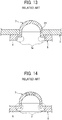
- the positioning structure disclosed in JP-2000-042641-A includes an article 2 constructed of sheet metal having a through hole 21 and an embossed component 5 including an embossed portion 7 projecting from a surface of a planar portion 6 constructed of sheet metal, as illustrated in FIG. 13 .
- the embossed portion 7 includes a straight portion continuous with the planar portion 6 is cylindrical and extends vertically relative to the planar portion 6, toward the tip side, and the projecting end of the embossed portion 7 has a spherical (hemispherical) face.
- the embossed portion 7 is fitted into the through hole 21, thereby positioning the article 2 with respect to the embossed component 5.
- the straight portion of the embossed portion 7 is made relatively long (high), to ensure reliable positioning of the article 2. Since the embossed component 5 is pressed to make the straight portion relatively high, a step 5a is created near the base end of the embossed portion 7. Thus, the conventional embossed component 5 includes the step 5a near the base end of the embossed portion 7, to secure the height of the straight portion.
- a thin portion F (see FIG. 14 ) is formed near the base end of the embossed portion 7.
- the strength of the thin portion F is sufficient when sheet metal having a thickness equal to or greater than 1 mm is used.
- the embossed component 5 is constructed of a thin sheet metal having a thickness equal to or smaller than 0.8 mm, the thin portion F becomes thinner. Then, the strength decreases, and the embossed portion 7 is liable to fall off.
- an object of the present disclosure is to provide an embossed component in which a straight portion of an embossed portion is relatively long and strength is secured even when a thin sheet metal is used and a housing and an image forming apparatus including the embossed component.
- the embossed component includes a planar portion and an embossed portion projecting from a surface of the planar portion.
- the embossed portion is tapered toward a tip side of the embossed portion and to be fitted into the through hole.
- the embossed portion includes a straight base end portion continuous with the planar portion and extending vertically with respect to the planar portion toward the tip side, and an opening is at a tip of the embossed portion.
- a housing includes the embossed component described above.
- an image forming apparatus includes the embossed component described above.
- the material on the tip side of the embossed portion easily flows toward the base end side during press molding of the embossed portion. Therefore, even when thin sheet metal is used and the straight portion is made relatively high, the embossed portion can be prevented from becoming too thin near the base end, and the strength of the embossed portion can be enhanced.
- FIG. 1 is a cross-sectional view schematically illustrating a main portion of an embossed component 1 according to one embodiment of the present disclosure.
- FIG. 2 is a plan view of the embossed component 1 illustrated in FIG. 1.
- FIG. 3 is a cross-sectional view illustrating a state in which an embossed portion 4 of the embossed component 1 illustrated in FIG. 1 is fitted into a through hole 21 of an article 2 and the article 2 is positioned with respect to the embossed component 1.
- the embossed component 1 illustrated in FIGS. 1 to 3 is constructed of a sheet metal member processed by pressing or the like.
- the embossed component 1 includes a planar portion 3 and an embossed portion 4 projecting from the surface of the planar portion 3.
- the embossed portion 4 is tapered toward the tip side thereof. As illustrated in FIG. 3 , the position of the article 2 having the through hole 21 is determined with respect to the embossed component 1, as the embossed portion 4 is fitted into the through hole 21.
- the shape of the embossed portion 4 will be described in further detail.
- the embossed portion 4 includes a straight portion 41 positioned on the base end side thereof, a tapered portion 42 located on the tip side thereof, and an opening 43 at the tip thereof.
- the straight portion 41 is continuous with the planar portion 3 and cylindrical, extending vertically relative to the planar portion 3 toward the tip side of the embossed portion 4.
- An inner diameter and an outer diameter d2 (see FIG. 1 ) of the straight portion 41 are substantially constant in the entire range in the height direction.
- the straight portion 41 has a height h that is greater than a thickness t of the planar portion 3.
- the "height h of the straight portion” is defined as the length from the surface of the planar portion 3 to the base end of the tapered portion 42 (that is, from the surface of the planar portion 3 to the start point of the tapered shape of the embossed portion 4).
- the straight portion 41 is a portion to be fitted into the through hole 21 of the article 2 and determines the position of the article 2.
- the article 2 is laid on or under the planar portion 3 with the surface thereof in contact with the planar portion 3.
- the article 2 is less likely to be come off from the embossed portion 4, and the article 2 is reliably positioned.
- the article 2 is produced by pressing or the like of sheet metal in the description above, articles to which aspects of the present disclosure are applied are not limited thereto but can be made of synthetic resin, for example.
- the article 2 and the embossed component 1 are directly in contact with each other, but another member (for example, a member for height adjustment) can be interposed between the article 2 and the planar portion 3 of the embossed component 1.
- another member for example, a member for height adjustment
- the tapered portion 42 is continuous with the straight portion 41 and extends in a cylindrical shape.
- the tapered portion 42 is shaped such that the inner diameter and the outer diameter gradually decrease with increasing distance from the straight portion 41.
- the tapered portion 42 guides the embossed portion 4 of the embossed component 1 into the through hole 21 of the article 2.
- the opening 43 is a portion enclosed by the edge of the tapered portion 42 and circular in plan view as illustrated in FIG. 2 .
- the embossed component 1 of the present embodiment is constructed of low carbon steel having a carbon content equal to or smaller than 0.25%.
- Examples of such steel includes SPCC, SPCD, SPCE, SPCG, SGCC, SGCE, and SGCD according to Japan Industrial Standard (JIS). Use of such a material facilitates pressing to be described later.
- JIS Japan Industrial Standard
- the present disclosure can be embodied in other ways, and various types of metal can be used for the embossed component 1.
- FIG. 4 is a cross-sectional view for explaining the method for forming the embossed component 1 illustrated in FIG. 1 .
- a perforation punch 14 is pushed toward a sheet metal member 11 placed on a perforation die 13, to form a through hole 12.
- FIG. 5 is a cross-sectional view for explaining the method for forming the embossed component 1 illustrated in FIG. 1 .
- the sheet metal member 11 having the through hole 12 in FIG. 4 is placed on a molding die 15, and a molding punch 16 is pushed to the center of the through hole 12 so as to form the embossed portion 4.
- FIG. 6 is a cross-sectional view illustrating the flow of material during manufacturing of the embossed portion 4 illustrated in FIG. 1 .
- the embossed component 1 illustrated in FIG. 1 is molded through primary pressing illustrated in FIG. 4 and secondary pressing illustrated in FIG. 5 .
- the sheet metal member 11 is placed on the perforation die 13, and the perforation punch 14 is pushed toward the sheet metal member 11 to form the through hole 12 in the sheet metal member 11.
- the through hole 12 becomes the opening 43 after undergoing the secondary pressing.
- the through hole 12 is circular, and a diameter 12d of the through hole 12 is smaller than a diameter d1 (see FIG. 1 ) of the resultant opening 43.
- the diameter 12d of the through hole 12 is appropriately changed depending on the required height h and the strength of the straight portion 41 and the thickness of the sheet metal member 11.
- the sheet metal member 11 in which the through hole 12 has been formed in the primary pressing is placed on the molding die 15, and the molding punch 16 is extruded toward the center of the through hole 12, to form the embossed portion 4.
- the molding punch 16 used here is columnar and has a hemispherical tip.
- the molding die 15 has a hole 15a having a diameter substantially equal to the outer diameter d2 of the straight portion 41 of the resultant product. As the sheet metal member 11 and the molding punch 16 are pushed into the hole 15a, the embossed portion 4 illustrated in FIG. 1 is formed. The amount by which the molding punch 16 extruded is adjusted depending on the size of the embossed portion 4 and the thickness of the sheet metal member 11.
- FIG. 14 is a view illustrating the flow of material during press molding of the conventional embossed portion 7 illustrated in FIG. 13 .
- the material at the tip of the embossed portion 7 flows in the directions indicated by arrows.
- the tip of the embossed portion 7 is continues, and the material becomes taut and hardly flows to the base end side. Therefore, the thin portion F illustrated in FIG. 14 is formed near the base end of the embossed portion 7.
- the material on the tip side of the embossed portion 4 flows in the directions indicated by arrows AR1 and AR2 illustrated in FIG. 6 .
- the material at the tip of the embossed portion becomes taut and is less likely to flow toward the base end side.
- the embossed portion 4 since the embossed portion 4 has the opening 43, the material on the tip side of the embossed portion 4 easily flows toward the base end side. That is, in the secondary pressing, the material on the tip side of the embossed portion 4 flows toward the base end side while the through hole 12 expands.
- the height h of the straight portion 41 can be secured without forming a step (the step 5a in FIG. 13 ) near the base end of the embossed portion 4 as in the conventional structure. Therefore, even when the sheet metal member 11 smaller in thickness than that used in the conventional structure is used and the height h of the straight portion 41 is set high, a base end portion E (see FIG. 6 ) of the embossed portion 4 is not made too thin, and the strength of the embossed portion 4 can be secured.
- the above-described structure of the embossed portion 4 is particularly effective when sheet metal having a smaller thickness (0.8 mm or less) than the conventional thickness is used. Even when the embossed portion 4 is constructed of sheet metal having the same thickness (about 1 mm) as the conventional thickness, the above-described structure is effective since both the height h of the straight portion 41 and the strength of the embossed portion 4 can be greater than those in the conventional structure.
- the conventional structure (see FIG. 13 ) having the step near the base end of the embossed portion is produced with sheet metal having a thickness equal to or greater than 1 mm.
- the sheet metal usable for the embossed portion 4 according to the present embodiment can be selectable from a wider range of sheet metal ranging from thicker sheet metal to thinner sheet metal. Further, a common mold can be used for a wide range of sheet metal.
- the inventors of the present disclosure have evaluated the strength and the guide function of the embossed portion 4, using a plurality of embossed components presented as Examples 1 to 9 in Table 1.
- Examples 1 to 9 are different in ratios of the inner diameter d1 of the opening 43 of the embossed portion 4 relative to the outer diameter d2 of the straight portion 41 (d1/d2) and the thickness of the sheet metal member 11 used for the embossed components.
- the results are presented in Table 1.
- Table 1 Example d1/d2 Sheet Metal Thickness (mm) 1.0 0.8 0.6 1 0.2 Poor Poor Poor 2 0.3 Good Good Good 3 0.4 Good Good Good 4 0.5 Good Good Good Good 5 0.6 Good Good Good 6 0.7 Good Good Good Good 7 0.8 Good Good Good Good 8 0.9 Good Good Good 9 1.0 Poor Poor Poor Poor
- Example 1 As presented in Table 1, in Example 1, the inner diameter d1 of the opening 43 divided by the outer diameter d2 of the straight portion 41 (d1/d2) is less than 0.3.
- the embossed portion 4 according to Example 1 was liable to be broken, failed to attain sufficient strength, and was evaluated as poor at all of thicknesses of 1.0 mm, 0.8 mm, and 0.6 mm. Further, in Example 9, the inner diameter d1 of the opening 43 divided by the outer diameter d2 of the straight portion 41 (d1/d2) is greater than 0.9.
- Example 9 at all of thicknesses of 1.0 mm, 0.8 mm, and 0.6 mm, the area of the tapered portion 42 serving as the guide was smaller, making it difficult to fit the embossed portion 4 into the through hole 21 of the article 2. Thus, Example 9 was evaluated as poor.
- Example 2 to 8 in which the inner diameter d1 of the opening 43 divided by the outer diameter d2 of the straight portion 41 (d1/d2) is equal to or greater than 0.3 and equal to or smaller than 0.9, at all of thicknesses of 1.0 mm, 0.8 mm, and 0.6 mm, both the strength and the guide function of the embossed portion 4 were good. Thus, Examples 2 to 8 were evaluated as good.
- FIG. 8 is a view of an embossed component 1A in which the inner diameter d1 of the opening 43 divided by the outer diameter d2 of the straight portion 41 is less than 0.3, as a comparative example.
- a breaking mechanism that can occur in the embossed component 1A.
- the following inconvenience is possible.
- the molding punch 16 is pressed against the sheet metal, the contact area between the front end portion of the molding punch 16 and the sheet metal is large, and the material on the tip side of the embossed portion 4 is less likely to flow to the base end side. Therefore, in the embossed component 1A, the vicinity of the base end of the embossed portion 4 is easily broken.
- FIG. 9 is a view of an embossed component 1B in which the inner diameter d1 of the opening 43 divided by the outer diameter d2 of the straight portion 41 is greater than 0.9, as another comparative example.
- the tapered portion 42 on the tip side of the embossed portion 4 that is, the guide portion, is small. As the guide portion becomes smaller, fitting the embossed portion 4 into the through hole 21 of the article 2 becomes difficult, and the positioning workability is degraded.
- the inventors of the present application measured the strength of a conventional product and the embossed component 1 according to the present embodiment, using a jig 17 illustrated in FIG. 7 .
- "Conventional product” mentioned here is the embossed portion 7 having the shape illustrated in FIG. 13 and constructed of sheet metal having a thickness of 0.8 mm.
- the jig 17 for strength testing illustrated in FIG. 7 includes an upper plate 18 and a lower plate 19 to sandwich the embossed component 1 and bolts for securing the upper plate 18 and the lower plate 19 to each other.
- the upper plate 18 includes a hole 18a for positioning the embossed portion 4 (or 7) and a projecting portion 18b.
- the embossed component 1 (or 5) was set on the jig 17, and one end of the embossed component 1 (the planar portion 3) and the projecting portion 18b were pulled in the directions indicated by arrows in FIG. 7 .
- the strength of the conventional embossed component and that of the embossed component 1 according to the present embodiment were measured.
- the results are presented in Table 2.
- Embodiment represents the embossed portion 4 having a shape illustrated in FIG. 1 and constructed of sheet metal having a thickness of 0.6 mm. Further, the inner diameter d1 of the opening 43 in the embossed portion 4 divided by the outer diameter d2 of the straight portion 41 is 0.7.
- the strength is about 200 N or less including variations.
- the embossed portion 7 may be broken due to assembling with the article 2, transportation, vibration, or the like.
- the strength of the product according to the present embodiment is high and about 900 N including variations.
- the strength is higher than that of the conventional product.
- the strength and the guide function of the embossed portion 4 are preferable.
- FIG. 10 is a plan view illustrating a variation of the embossed component illustrated in FIG. 1 .
- the same components as those of the above embodiment illustrated in FIGS. 1 to 9 ) are denoted by the same reference numerals, and descriptions thereof are omitted.
- An embossed component 1C, illustrated in FIG. 10 has an opening 44 that is tetragonal in plan view instead of the above-described opening 43.
- the shape of the opening (43 or 44 in the drawings) of the embossed portion 4 according to this disclosure is not limited to a circle (perfect circle) but can be a polygon such as a triangle, a quadrangle, or the like, or can be an ellipse.
- the strength and the guide function of the embossed portion 4 are equivalent to those in the structure in which the opening is circular and superior to the strength and the guide function of the embossed portion 7 having the shape illustrated in FIG. 13 and constructed of sheet metal having a thickness of 0.8 mm.
- the straight portion 41 have a cylindrical shape that is circular (perfect circle) in plan view, but the present disclosure can be embodied otherwise.
- the straight portion 41 can have a cylindrical shape that is elliptical in plan view.
- the outer shape of the straight portion 41 is elliptical or the shape of the opening (43 or 44 in the drawings) at the tip of the embossed portion 4 is polygonal or elliptical, the inner diameters and the outer diameters of such shapes are converted into circle-equivalent diameters. Then, the above-described ratio of the inner diameter d1 of the opening (43 or 44 in the drawings) relative to the outer diameter d2 of the straight portion 41 can be applied.
- An image forming apparatus 100 illustrated in FIG. 11 includes an optical scanner 111, an image forming unit 113 including a photoconductor and an intermediate transfer belt 114, a transfer device 115, a fixing device 116, a sheet feeding tray 117 to accommodate sheets S of various sizes, and an output tray 118.
- the optical scanner 111 exposes the photoconductor to form an electrostatic latent image
- the image forming unit 113 forms a toner image on the photoconductor
- the transfer device 115 transfers the toner image onto the sheet S fed from the sheet feeding tray 117.
- the fixing device 116 fixes the toner image transferred on the sheet S.
- the sheet S on which the toner image is fixed is discharged to the output tray 118 outside the apparatus.
- the embossed component 1 illustrated in FIG. 1 described above is used, for example, for a bracket 10 illustrated in FIG. 12 .
- the bracket 10 is a part of the housing of the optical scanner 111 in the image forming apparatus 100 illustrated in FIG. 11 .
- the bracket 10 is laid on or under another part (a sheet metal member, corresponding to the article 2 in FIG. 3 ), which is to be positioned relative to the housing.
- the bracket 10 can be constructed of sheet metal having a thickness (0.8 mm or less) smaller than the conventional thickness. Accordingly, the cost can be reduced, and the apparatus can be reduced in weight.
- embossed components are applicable to portions of the image forming apparatus 100 other than the housing and further to various apparatuses other than image forming apparatuses.
Landscapes
- Engineering & Computer Science (AREA)
- Mechanical Engineering (AREA)
- Physics & Mathematics (AREA)
- General Physics & Mathematics (AREA)
- General Engineering & Computer Science (AREA)
- Electrophotography Configuration And Component (AREA)
- Shaping Metal By Deep-Drawing, Or The Like (AREA)
- Accessory Devices And Overall Control Thereof (AREA)
- Laser Beam Printer (AREA)
Abstract
Description
- The present disclosure relates to an embossed component, and a housing and an image forming apparatus including the embossed component.
- There are positioning structures employing an embossed portion. For example, in a through hole in a sheet metal component, an embossed portion of a separate component is fitted, thereby coupling the two components (see
JP-2000-042641-A - The positioning structure disclosed in
JP-2000-042641-A article 2 constructed of sheet metal having a throughhole 21 and an embossedcomponent 5 including an embossedportion 7 projecting from a surface of aplanar portion 6 constructed of sheet metal, as illustrated inFIG. 13 . On a base end side, the embossedportion 7 includes a straight portion continuous with theplanar portion 6 is cylindrical and extends vertically relative to theplanar portion 6, toward the tip side, and the projecting end of the embossedportion 7 has a spherical (hemispherical) face. In this positioning structure, the embossedportion 7 is fitted into the throughhole 21, thereby positioning thearticle 2 with respect to the embossedcomponent 5. - In the conventional positioning structure illustrated in
FIG. 13 , the straight portion of the embossedportion 7 is made relatively long (high), to ensure reliable positioning of thearticle 2. Since the embossedcomponent 5 is pressed to make the straight portion relatively high, astep 5a is created near the base end of the embossedportion 7. Thus, the conventional embossedcomponent 5 includes thestep 5a near the base end of the embossedportion 7, to secure the height of the straight portion. - To reduce the cost, in the conventional embossed
component 5 described above, use of thinner sheet metal is preferred. - In the conventional embossed
component 5, as thestep 5a is formed, a thin portion F (seeFIG. 14 ) is formed near the base end of the embossedportion 7. The strength of the thin portion F is sufficient when sheet metal having a thickness equal to or greater than 1 mm is used. However, when the embossedcomponent 5 is constructed of a thin sheet metal having a thickness equal to or smaller than 0.8 mm, the thin portion F becomes thinner. Then, the strength decreases, and the embossedportion 7 is liable to fall off. - In view of the foregoing, an object of the present disclosure is to provide an embossed component in which a straight portion of an embossed portion is relatively long and strength is secured even when a thin sheet metal is used and a housing and an image forming apparatus including the embossed component.
- In order to achieve the above-described object, there is provided an embossed component for positioning an article having a through hole, as described in appended claims. Advantageous embodiments are defined by the dependent claims.
- Advantageously, the embossed component includes a planar portion and an embossed portion projecting from a surface of the planar portion. The embossed portion is tapered toward a tip side of the embossed portion and to be fitted into the through hole. The embossed portion includes a straight base end portion continuous with the planar portion and extending vertically with respect to the planar portion toward the tip side, and an opening is at a tip of the embossed portion.
- Advantageously, a housing includes the embossed component described above.
- Advantageously, an image forming apparatus includes the embossed component described above.
- Accordingly, owing to the opening at the tip of the embossed portion, the material on the tip side of the embossed portion easily flows toward the base end side during press molding of the embossed portion. Therefore, even when thin sheet metal is used and the straight portion is made relatively high, the embossed portion can be prevented from becoming too thin near the base end, and the strength of the embossed portion can be enhanced.
- A more complete appreciation of the disclosure and many of the attendant advantages thereof will be readily obtained as the same becomes better understood by reference to the following detailed description when considered in connection with the accompanying drawings, wherein:
-
FIG. 1 is a cross-sectional view schematically illustrating a main portion of an embossed component according to an embodiment of the present disclosure; -
FIG. 2 is a plan view of the embossed component illustrated inFIG. 1 ; -
FIG. 3 is a cross-sectional view illustrating an article positioned with respect to the embossed component illustrated inFIG. 1 , with an embossed portion of the embossed component fitted into a through hole of the article; -
FIG. 4 is a cross-sectional view for explaining a method for forming the embossed component illustrated inFIG. 1 , in which a perforation punch is pushed toward a sheet metal member placed on a perforation die, to form the through hole; -
FIG. 5 is a cross-sectional view for explaining a method for forming the embossed component illustrated inFIG. 1 , in which the sheet metal member having the through hole inFIG. 4 is placed on a molding die, and a molding punch is pushed toward the center of the through hole, to form the embossed portion; -
FIG. 6 is a cross-sectional view illustrating a flow of material during manufacturing of the embossed portion illustrated inFIG. 1 ; -
FIG. 7 is a view of an example jig for measuring the strength of an embossed component; -
FIG. 8 is a view of an embossed component according to a comparative example, in which the ratio of the inner diameter of the opening of the embossed portion relative to the outer diameter of the straight portion is smaller than a predetermined range; -
FIG. 9 is a view of an embossed component according to another comparative example, in which the ratio of the inner diameter of the opening of the embossed portion relative to the outer diameter of the straight portion is greater than the predetermined range; -
FIG. 10 is a plan view illustrating a variation of the embossed component illustrated inFIG. 1 ; -
FIG. 11 is a schematic view of an image forming apparatus to which an embossed component according to an embodiment is applied; -
FIG. 12 is a perspective view of a bracket as an example of the embossed component used in the image forming apparatus illustrated inFIG. 11 ; -
FIG. 13 is a cross-sectional view illustrating an article positioned with respect to a conventional embossed component, with an embossed portion of the embossed component fitted into a through hole of the article; and -
FIG. 14 is a cross-sectional view illustrating a flow of material during manufacturing of the embossed portion illustrated inFIG. 13 . - The accompanying drawings are intended to depict embodiments of the present invention and should not be interpreted to limit the scope thereof. The accompanying drawings are not to be considered as drawn to scale unless explicitly noted.
- In describing embodiments illustrated in the drawings, specific terminology is employed for the sake of clarity. However, the disclosure of this patent specification is not intended to be limited to the specific terminology so selected, and it is to be understood that each specific element includes all technical equivalents that operate in a similar manner and achieve a similar result.
- Referring now to the drawings, wherein like reference numerals designate identical or corresponding parts throughout the several views thereof, embossed components and an image forming apparatus according to embodiments of this disclosure are described. As used herein, the singular forms "a", "an", and "the" are intended to include the plural forms as well, unless the context clearly indicates otherwise.
- An embossed component according to one embodiment of the present disclosure will be described with reference to
FIGS. 1 to 9 .FIG. 1 is a cross-sectional view schematically illustrating a main portion of an embossedcomponent 1 according to one embodiment of the present disclosure.FIG. 2 is a plan view of the embossedcomponent 1 illustrated inFIG. 1. FIG. 3 is a cross-sectional view illustrating a state in which an embossedportion 4 of the embossedcomponent 1 illustrated inFIG. 1 is fitted into athrough hole 21 of anarticle 2 and thearticle 2 is positioned with respect to the embossedcomponent 1. - The embossed
component 1 illustrated inFIGS. 1 to 3 is constructed of a sheet metal member processed by pressing or the like. The embossedcomponent 1 includes aplanar portion 3 and an embossedportion 4 projecting from the surface of theplanar portion 3. The embossedportion 4 is tapered toward the tip side thereof. As illustrated inFIG. 3 , the position of thearticle 2 having the throughhole 21 is determined with respect to the embossedcomponent 1, as the embossedportion 4 is fitted into thethrough hole 21. - The shape of the embossed
portion 4 will be described in further detail. The embossedportion 4 includes astraight portion 41 positioned on the base end side thereof, atapered portion 42 located on the tip side thereof, and anopening 43 at the tip thereof. - The
straight portion 41 is continuous with theplanar portion 3 and cylindrical, extending vertically relative to theplanar portion 3 toward the tip side of the embossedportion 4. An inner diameter and an outer diameter d2 (seeFIG. 1 ) of thestraight portion 41 are substantially constant in the entire range in the height direction. Thestraight portion 41 has a height h that is greater than a thickness t of theplanar portion 3. In the present specification, the "height h of the straight portion" is defined as the length from the surface of theplanar portion 3 to the base end of the tapered portion 42 (that is, from the surface of theplanar portion 3 to the start point of the tapered shape of the embossed portion 4). - The
straight portion 41 is a portion to be fitted into thethrough hole 21 of thearticle 2 and determines the position of thearticle 2. Thearticle 2 is laid on or under theplanar portion 3 with the surface thereof in contact with theplanar portion 3. The inner surface of the throughhole 21, which is circular in plan view, conforms to the outer surface of thestraight portion 41. - In such a structure, since the height h of the
straight portion 41 is greater than the thickness t of theplanar portion 3, thearticle 2 is less likely to be come off from the embossedportion 4, and thearticle 2 is reliably positioned. In addition, although thearticle 2 is produced by pressing or the like of sheet metal in the description above, articles to which aspects of the present disclosure are applied are not limited thereto but can be made of synthetic resin, for example. - In the example illustrated in
FIG. 3 , thearticle 2 and theembossed component 1 are directly in contact with each other, but another member (for example, a member for height adjustment) can be interposed between thearticle 2 and theplanar portion 3 of the embossedcomponent 1. - The tapered
portion 42 is continuous with thestraight portion 41 and extends in a cylindrical shape. The taperedportion 42 is shaped such that the inner diameter and the outer diameter gradually decrease with increasing distance from thestraight portion 41. The taperedportion 42 guides the embossedportion 4 of the embossedcomponent 1 into the throughhole 21 of thearticle 2. - The
opening 43 is a portion enclosed by the edge of the taperedportion 42 and circular in plan view as illustrated inFIG. 2 . - In addition, the embossed
component 1 of the present embodiment is constructed of low carbon steel having a carbon content equal to or smaller than 0.25%. Examples of such steel includes SPCC, SPCD, SPCE, SPCG, SGCC, SGCE, and SGCD according to Japan Industrial Standard (JIS). Use of such a material facilitates pressing to be described later. However, the present disclosure can be embodied in other ways, and various types of metal can be used for the embossedcomponent 1. - A method for forming the
embossed component 1 will be described.FIG. 4 is a cross-sectional view for explaining the method for forming theembossed component 1 illustrated inFIG. 1 . InFIG. 4 , aperforation punch 14 is pushed toward asheet metal member 11 placed on aperforation die 13, to form a throughhole 12.FIG. 5 is a cross-sectional view for explaining the method for forming theembossed component 1 illustrated inFIG. 1 . InFIG. 5 , thesheet metal member 11 having the throughhole 12 inFIG. 4 is placed on amolding die 15, and amolding punch 16 is pushed to the center of the throughhole 12 so as to form the embossedportion 4.FIG. 6 is a cross-sectional view illustrating the flow of material during manufacturing of the embossedportion 4 illustrated inFIG. 1 . - The embossed
component 1 illustrated inFIG. 1 is molded through primary pressing illustrated inFIG. 4 and secondary pressing illustrated inFIG. 5 . - In the primary pressing illustrated in
FIG. 4 , thesheet metal member 11 is placed on the perforation die 13, and theperforation punch 14 is pushed toward thesheet metal member 11 to form the throughhole 12 in thesheet metal member 11. The throughhole 12 becomes theopening 43 after undergoing the secondary pressing. In the present embodiment, the throughhole 12 is circular, and adiameter 12d of the throughhole 12 is smaller than a diameter d1 (seeFIG. 1 ) of theresultant opening 43. Thediameter 12d of the throughhole 12 is appropriately changed depending on the required height h and the strength of thestraight portion 41 and the thickness of thesheet metal member 11. - In the secondary pressing illustrated in
FIG. 5 , thesheet metal member 11 in which the throughhole 12 has been formed in the primary pressing is placed on the molding die 15, and themolding punch 16 is extruded toward the center of the throughhole 12, to form the embossedportion 4. Further, themolding punch 16 used here is columnar and has a hemispherical tip. In addition, the molding die 15 has ahole 15a having a diameter substantially equal to the outer diameter d2 of thestraight portion 41 of the resultant product. As thesheet metal member 11 and themolding punch 16 are pushed into thehole 15a, the embossedportion 4 illustrated inFIG. 1 is formed. The amount by which themolding punch 16 extruded is adjusted depending on the size of the embossedportion 4 and the thickness of thesheet metal member 11. When the value calculated by dividing the inner diameter d1 (seeFIG. 1 ) of theopening 43 of the finished product with thedimeter 12d (seeFIG. 5 ) of the through hole 12 (d1/12d) is equal to or smaller than 4.0, breakage of the embossedportion 4 hardly occurs during the secondary pressing. -
FIG. 14 is a view illustrating the flow of material during press molding of the conventional embossedportion 7 illustrated inFIG. 13 . During the press molding of the embossedportion 7, as the punch is pressed against the sheet metal, the material at the tip of the embossedportion 7 flows in the directions indicated by arrows. However, the tip of the embossedportion 7 is continues, and the material becomes taut and hardly flows to the base end side. Therefore, the thin portion F illustrated inFIG. 14 is formed near the base end of the embossedportion 7. - When the
molding punch 16 is pressed against thesheet metal member 11 in the secondary pressing, the material on the tip side of the embossedportion 4 flows in the directions indicated by arrows AR1 and AR2 illustrated inFIG. 6 . At that time, in the conventional embossed shape having no opening illustrated inFIG. 14 , the material at the tip of the embossed portion becomes taut and is less likely to flow toward the base end side. By contrast, in the present embodiment, since the embossedportion 4 has theopening 43, the material on the tip side of the embossedportion 4 easily flows toward the base end side. That is, in the secondary pressing, the material on the tip side of the embossedportion 4 flows toward the base end side while the throughhole 12 expands. Therefore, in the embossedcomponent 1 according to the present embodiment, the height h of thestraight portion 41 can be secured without forming a step (thestep 5a inFIG. 13 ) near the base end of the embossedportion 4 as in the conventional structure. Therefore, even when thesheet metal member 11 smaller in thickness than that used in the conventional structure is used and the height h of thestraight portion 41 is set high, a base end portion E (seeFIG. 6 ) of the embossedportion 4 is not made too thin, and the strength of the embossedportion 4 can be secured. - The above-described structure of the embossed
portion 4 is particularly effective when sheet metal having a smaller thickness (0.8 mm or less) than the conventional thickness is used. Even when the embossedportion 4 is constructed of sheet metal having the same thickness (about 1 mm) as the conventional thickness, the above-described structure is effective since both the height h of thestraight portion 41 and the strength of the embossedportion 4 can be greater than those in the conventional structure. The conventional structure (seeFIG. 13 ) having the step near the base end of the embossed portion is produced with sheet metal having a thickness equal to or greater than 1 mm. By contrast, the sheet metal usable for the embossedportion 4 according to the present embodiment can be selectable from a wider range of sheet metal ranging from thicker sheet metal to thinner sheet metal. Further, a common mold can be used for a wide range of sheet metal. - The inventors of the present disclosure have evaluated the strength and the guide function of the embossed
portion 4, using a plurality of embossed components presented as Examples 1 to 9 in Table 1. Examples 1 to 9 are different in ratios of the inner diameter d1 of theopening 43 of the embossedportion 4 relative to the outer diameter d2 of the straight portion 41 (d1/d2) and the thickness of thesheet metal member 11 used for the embossed components. The results are presented in Table 1.Table 1 Example d1/d2 Sheet Metal Thickness (mm) 1.0 0.8 0.6 1 0.2 Poor Poor Poor 2 0.3 Good Good Good 3 0.4 Good Good Good 4 0.5 Good Good Good 5 0.6 Good Good Good 6 0.7 Good Good Good 7 0.8 Good Good Good 8 0.9 Good Good Good 9 1.0 Poor Poor Poor - As presented in Table 1, in Example 1, the inner diameter d1 of the
opening 43 divided by the outer diameter d2 of the straight portion 41 (d1/d2) is less than 0.3. The embossedportion 4 according to Example 1 was liable to be broken, failed to attain sufficient strength, and was evaluated as poor at all of thicknesses of 1.0 mm, 0.8 mm, and 0.6 mm. Further, in Example 9, the inner diameter d1 of theopening 43 divided by the outer diameter d2 of the straight portion 41 (d1/d2) is greater than 0.9. In Example 9, at all of thicknesses of 1.0 mm, 0.8 mm, and 0.6 mm, the area of the taperedportion 42 serving as the guide was smaller, making it difficult to fit the embossedportion 4 into the throughhole 21 of thearticle 2. Thus, Example 9 was evaluated as poor. In Examples 2 to 8 in which the inner diameter d1 of theopening 43 divided by the outer diameter d2 of the straight portion 41 (d1/d2) is equal to or greater than 0.3 and equal to or smaller than 0.9, at all of thicknesses of 1.0 mm, 0.8 mm, and 0.6 mm, both the strength and the guide function of the embossedportion 4 were good. Thus, Examples 2 to 8 were evaluated as good. -
FIG. 8 is a view of an embossedcomponent 1A in which the inner diameter d1 of theopening 43 divided by the outer diameter d2 of thestraight portion 41 is less than 0.3, as a comparative example. Referring toFIG. 8 , descriptions are given of a breaking mechanism that can occur in the embossedcomponent 1A. As illustrated inFIG. 8 , in a structure in which the ratio of the inner diameter d1 of theopening 43 relative to the outer diameter d2 of thestraight portion 41 is smaller than the above range, the following inconvenience is possible. When themolding punch 16 is pressed against the sheet metal, the contact area between the front end portion of themolding punch 16 and the sheet metal is large, and the material on the tip side of the embossedportion 4 is less likely to flow to the base end side. Therefore, in the embossedcomponent 1A, the vicinity of the base end of the embossedportion 4 is easily broken. -
FIG. 9 is a view of anembossed component 1B in which the inner diameter d1 of theopening 43 divided by the outer diameter d2 of thestraight portion 41 is greater than 0.9, as another comparative example. Referring toFIG. 9 , descriptions are given of action of the embossedcomponent 1B. As illustrated inFIG. 9 , in the structure in which the ratio of the inner diameter d1 of theopening 43 relative to the outer diameter d2 of thestraight portion 41 is greater than the above range, as apparent fromFIG. 9 , the taperedportion 42 on the tip side of the embossedportion 4, that is, the guide portion, is small. As the guide portion becomes smaller, fitting theembossed portion 4 into the throughhole 21 of thearticle 2 becomes difficult, and the positioning workability is degraded. - Furthermore, the inventors of the present application measured the strength of a conventional product and the
embossed component 1 according to the present embodiment, using ajig 17 illustrated inFIG. 7 . "Conventional product" mentioned here is the embossedportion 7 having the shape illustrated inFIG. 13 and constructed of sheet metal having a thickness of 0.8 mm. Thejig 17 for strength testing illustrated inFIG. 7 includes anupper plate 18 and alower plate 19 to sandwich the embossedcomponent 1 and bolts for securing theupper plate 18 and thelower plate 19 to each other. Theupper plate 18 includes ahole 18a for positioning the embossed portion 4 (or 7) and a projectingportion 18b. The embossed component 1 (or 5) was set on thejig 17, and one end of the embossed component 1 (the planar portion 3) and the projectingportion 18b were pulled in the directions indicated by arrows inFIG. 7 . Thus, the strength of the conventional embossed component and that of the embossedcomponent 1 according to the present embodiment were measured. The results are presented in Table 2. - In Table 2, "Embodiment" represents the embossed
portion 4 having a shape illustrated inFIG. 1 and constructed of sheet metal having a thickness of 0.6 mm. Further, the inner diameter d1 of theopening 43 in the embossedportion 4 divided by the outer diameter d2 of thestraight portion 41 is 0.7.Table 2 Strength Conventional Product 200 N or below Embodiment About 900 N - As presented in Table 2, in the case of the conventional product, the strength is about 200 N or less including variations. With this strength, the embossed
portion 7 may be broken due to assembling with thearticle 2, transportation, vibration, or the like. However, the strength of the product according to the present embodiment is high and about 900 N including variations. In addition, even in the product according to the present embodiment in which the inner diameter d1 of theopening 43 in the embossedportion 4 divided by the outer diameter d2 of thestraight portion 41 is 0.3, the strength is higher than that of the conventional product. - Thus, in the embossed
component 1, when the inner diameter d1 of theopening 43 divided by the outer diameter d2 of thestraight portion 41 is equal to or greater than 0.3 and equal to or smaller than 0.9, the strength and the guide function of the embossedportion 4 are preferable. - A variation of the above embodiment will be described with reference to
FIG. 10. FIG. 10 is a plan view illustrating a variation of the embossed component illustrated inFIG. 1 . InFIG. 10 , the same components as those of the above embodiment (illustrated inFIGS. 1 to 9 ) are denoted by the same reference numerals, and descriptions thereof are omitted. - An
embossed component 1C, illustrated inFIG. 10 , according to the variation has anopening 44 that is tetragonal in plan view instead of the above-describedopening 43. Thus, the shape of the opening (43 or 44 in the drawings) of the embossedportion 4 according to this disclosure is not limited to a circle (perfect circle) but can be a polygon such as a triangle, a quadrangle, or the like, or can be an ellipse. Further, according to the present disclosure, even an embossed portion having a polygonal or elliptical opening, the strength and the guide function of the embossedportion 4 are equivalent to those in the structure in which the opening is circular and superior to the strength and the guide function of the embossedportion 7 having the shape illustrated inFIG. 13 and constructed of sheet metal having a thickness of 0.8 mm. - In the above-described embodiment (
FIGS. 1 to 9 ) and the variation (FIG. 10 ), thestraight portion 41 have a cylindrical shape that is circular (perfect circle) in plan view, but the present disclosure can be embodied otherwise. Thestraight portion 41 can have a cylindrical shape that is elliptical in plan view. In the structure in which the outer shape of thestraight portion 41 is elliptical or the shape of the opening (43 or 44 in the drawings) at the tip of the embossedportion 4 is polygonal or elliptical, the inner diameters and the outer diameters of such shapes are converted into circle-equivalent diameters. Then, the above-described ratio of the inner diameter d1 of the opening (43 or 44 in the drawings) relative to the outer diameter d2 of thestraight portion 41 can be applied. - Next, descriptions are given below of an image forming apparatus to which the embossed
component 1 described above is applied, according to an embodiment, with reference toFIG. 11 . Animage forming apparatus 100 illustrated inFIG. 11 includes anoptical scanner 111, animage forming unit 113 including a photoconductor and anintermediate transfer belt 114, atransfer device 115, a fixingdevice 116, asheet feeding tray 117 to accommodate sheets S of various sizes, and anoutput tray 118. - In the
image forming apparatus 100, theoptical scanner 111 exposes the photoconductor to form an electrostatic latent image, theimage forming unit 113 forms a toner image on the photoconductor, and thetransfer device 115 transfers the toner image onto the sheet S fed from thesheet feeding tray 117. Then, the fixingdevice 116 fixes the toner image transferred on the sheet S. The sheet S on which the toner image is fixed is discharged to theoutput tray 118 outside the apparatus. - In the
image forming apparatus 100, the embossedcomponent 1 illustrated inFIG. 1 described above is used, for example, for abracket 10 illustrated inFIG. 12 . Thebracket 10 is a part of the housing of theoptical scanner 111 in theimage forming apparatus 100 illustrated inFIG. 11 . Thebracket 10 is laid on or under another part (a sheet metal member, corresponding to thearticle 2 inFIG. 3 ), which is to be positioned relative to the housing. In theimage forming apparatus 100, thebracket 10 can be constructed of sheet metal having a thickness (0.8 mm or less) smaller than the conventional thickness. Accordingly, the cost can be reduced, and the apparatus can be reduced in weight. - Although the description above concerns an example of applying the embossed
component 1 to the housing of theimage forming apparatus 100, embossed components according to aspects of the present disclosure are applicable to portions of theimage forming apparatus 100 other than the housing and further to various apparatuses other than image forming apparatuses.
Claims (6)
- An embossed component (1) for positioning an article (2) having a through hole (21), the embossed component (1) comprising:a planar portion (3); andan embossed portion (4) projecting from a surface of the planar portion (3) and tapered toward a tip side of the embossed portion (4), the embossed portion (4) to be fitted into the through hole (21),wherein the embossed portion (4) includes:a straight base end portion (41) continuous with the planar portion (3) and extending vertically with respect to the planar portion (3) toward the tip side of the embossed portion (4); andan opening (43) at a tip of the embossed portion (4).
- The embossed component (1) according to claim 1, wherein a height of the straight base end portion (41) is greater than a thickness of the planar portion (3).
- The embossed component (1) according to claim 1 or 2, wherein an inner diameter of the opening (43) divided by an outer diameter of the straight base end portion (41) is equal to or greater than 0.3 and equal to or smaller than 0.9.
- The embossed component (1) according to any one of claims 1 to 3, wherein the opening (43) of the embossed portion (4) has one of a circular shape and a polygonal shape.
- A housing (10) comprising the embossed component (1) according to any one of claims 1 to 4.
- An image forming apparatus (100) comprising the embossed component (1) according to any one of claims 1 to 4.
Applications Claiming Priority (1)
| Application Number | Priority Date | Filing Date | Title |
|---|---|---|---|
| JP2018045660A JP7081228B2 (en) | 2018-03-13 | 2018-03-13 | Member with embossed part, housing equipped with it, and image forming device |
Publications (2)
| Publication Number | Publication Date |
|---|---|
| EP3550379A1 true EP3550379A1 (en) | 2019-10-09 |
| EP3550379B1 EP3550379B1 (en) | 2021-10-13 |
Family
ID=65657197
Family Applications (1)
| Application Number | Title | Priority Date | Filing Date |
|---|---|---|---|
| EP19154862.7A Not-in-force EP3550379B1 (en) | 2018-03-13 | 2019-01-31 | Embossed component and housing and image forming apparatus including same |
Country Status (3)
| Country | Link |
|---|---|
| US (1) | US11156244B2 (en) |
| EP (1) | EP3550379B1 (en) |
| JP (1) | JP7081228B2 (en) |
Families Citing this family (3)
| Publication number | Priority date | Publication date | Assignee | Title |
|---|---|---|---|---|
| JP4374310B2 (en) * | 2004-12-01 | 2009-12-02 | 株式会社島精機製作所 | Knitting method of knitted fabric |
| JP4336306B2 (en) * | 2004-12-28 | 2009-09-30 | 株式会社島精機製作所 | Method for knitting tubular knitted fabric |
| WO2008120476A1 (en) * | 2007-04-03 | 2008-10-09 | Shima Seiki Mfg., Ltd. | Socks with heels, and their knitting method |
Citations (6)
| Publication number | Priority date | Publication date | Assignee | Title |
|---|---|---|---|---|
| JPH09295071A (en) * | 1996-04-26 | 1997-11-18 | Toshiba Electron Eng Corp | Press processing method and apparatus |
| JP2000042641A (en) | 1998-07-29 | 2000-02-15 | Ricoh Co Ltd | Embossing structure for positioning and mold for processing embossing structure for positioning |
| US20040244459A1 (en) * | 2003-06-09 | 2004-12-09 | Minako Matsuoka | Method and apparatus for producing thin walled tubular product with thick walled flange |
| US20110016944A1 (en) * | 2009-07-24 | 2011-01-27 | Canon Kabushiki Kaisha | Method of producing metallic member |
| US20110042545A1 (en) * | 2009-08-20 | 2011-02-24 | Dustin Daniel Fichter | Anti-Tip Stability System Integral to an Imaging Apparatus |
| US20150336155A1 (en) * | 2013-01-11 | 2015-11-26 | Kabushiki Kaisha F.C.C. | Method for forming a pressed component, method for manufacturing a pressed component, and die apparatus for forming a pressed component |
Family Cites Families (8)
| Publication number | Priority date | Publication date | Assignee | Title |
|---|---|---|---|---|
| JP3494412B2 (en) | 1993-02-15 | 2004-02-09 | 積水ハウス株式会社 | Equipment for embossing and drilling |
| JPH07299529A (en) * | 1994-05-02 | 1995-11-14 | Xerox Corp | Locating shape |
| JP2001050353A (en) | 1999-08-11 | 2001-02-23 | Mitsubishi Motors Corp | Belt element for continuously variable transmission, method of forming element for continuously variable transmission belt, and belt for continuously variable transmission |
| KR100371598B1 (en) * | 1999-10-29 | 2003-02-11 | 가부시키가이샤 리코 | Apparatus for smoothly connecting driving force conveying joint with driving force receiving joint |
| JP5176508B2 (en) | 2007-12-04 | 2013-04-03 | 株式会社リコー | Fastening structure, blade structure, developing device, and image forming apparatus |
| JP6003232B2 (en) | 2012-05-28 | 2016-10-05 | 株式会社リコー | Fastening body for plate member, fastening method for plate member, and image forming apparatus |
| JP2014062658A (en) | 2012-09-20 | 2014-04-10 | Fujitsu Ltd | Cooling module and loop type heat pipe |
| JP6268986B2 (en) | 2013-11-28 | 2018-01-31 | 株式会社リコー | Caulking fastening structure, fastening part structure, and image forming apparatus |
-
2018
- 2018-03-13 JP JP2018045660A patent/JP7081228B2/en active Active
-
2019
- 2019-01-30 US US16/262,173 patent/US11156244B2/en not_active Expired - Fee Related
- 2019-01-31 EP EP19154862.7A patent/EP3550379B1/en not_active Not-in-force
Patent Citations (6)
| Publication number | Priority date | Publication date | Assignee | Title |
|---|---|---|---|---|
| JPH09295071A (en) * | 1996-04-26 | 1997-11-18 | Toshiba Electron Eng Corp | Press processing method and apparatus |
| JP2000042641A (en) | 1998-07-29 | 2000-02-15 | Ricoh Co Ltd | Embossing structure for positioning and mold for processing embossing structure for positioning |
| US20040244459A1 (en) * | 2003-06-09 | 2004-12-09 | Minako Matsuoka | Method and apparatus for producing thin walled tubular product with thick walled flange |
| US20110016944A1 (en) * | 2009-07-24 | 2011-01-27 | Canon Kabushiki Kaisha | Method of producing metallic member |
| US20110042545A1 (en) * | 2009-08-20 | 2011-02-24 | Dustin Daniel Fichter | Anti-Tip Stability System Integral to an Imaging Apparatus |
| US20150336155A1 (en) * | 2013-01-11 | 2015-11-26 | Kabushiki Kaisha F.C.C. | Method for forming a pressed component, method for manufacturing a pressed component, and die apparatus for forming a pressed component |
Also Published As
| Publication number | Publication date |
|---|---|
| US20190285100A1 (en) | 2019-09-19 |
| JP2019155424A (en) | 2019-09-19 |
| JP7081228B2 (en) | 2022-06-07 |
| US11156244B2 (en) | 2021-10-26 |
| EP3550379B1 (en) | 2021-10-13 |
Similar Documents
| Publication | Publication Date | Title |
|---|---|---|
| EP3550379B1 (en) | Embossed component and housing and image forming apparatus including same | |
| US10749147B2 (en) | Pouch forming device and method and facility for producing secondary battery comprising the pouch forming device | |
| EP1898273B1 (en) | Developer Amount Regulation Blade Structure | |
| JP2012173527A (en) | Lens mirror frame and lens assembly | |
| US20210086388A1 (en) | Notching apparatus and method for secondary battery | |
| US9335711B2 (en) | Fitting structure for a plate-form member | |
| EP3182725A1 (en) | Speaker diaphragm, speaker including same, and method for manufacturing speaker diaphragm | |
| US10626907B2 (en) | Joining method | |
| JP2002103479A (en) | Blank mold | |
| US11173616B2 (en) | Gripping mechanism that grips and releases component, and assembly device | |
| US11110507B2 (en) | Convex portion, method of manufacturing convex portion, positioning structure | |
| US20070286673A1 (en) | Method for fastening plate-like members and fastening structure for plate-like members | |
| US8564891B2 (en) | Holding apparatus, optical apparatus, and telescope | |
| JP2021122838A (en) | Method for manufacturing molding material | |
| KR101364916B1 (en) | Burring process and the system of vehicle panel iron plate | |
| JP3206250U (en) | Washer with spring washer | |
| US10974302B2 (en) | Manufacturing method for cylindrical portion | |
| US20020170774A1 (en) | Speaker parts and method of manufacturing same | |
| JP4381970B2 (en) | Developer regulating member, method for producing developer regulating member, developing machine using the same, and image forming apparatus or printer using the developing machine | |
| JP5941929B2 (en) | Adjustable lens mount for belt lens | |
| CN115473021B (en) | Cavity Filter | |
| JP2023149445A (en) | Square can manufacturing method and square can manufacturing device | |
| US10594882B1 (en) | Document feeding structure | |
| US10190614B2 (en) | Fixing device | |
| JP2020199583A (en) | Punching device |
Legal Events
| Date | Code | Title | Description |
|---|---|---|---|
| PUAI | Public reference made under article 153(3) epc to a published international application that has entered the european phase |
Free format text: ORIGINAL CODE: 0009012 |
|
| STAA | Information on the status of an ep patent application or granted ep patent |
Free format text: STATUS: REQUEST FOR EXAMINATION WAS MADE |
|
| 17P | Request for examination filed |
Effective date: 20190131 |
|
| AK | Designated contracting states |
Kind code of ref document: A1 Designated state(s): AL AT BE BG CH CY CZ DE DK EE ES FI FR GB GR HR HU IE IS IT LI LT LU LV MC MK MT NL NO PL PT RO RS SE SI SK SM TR |
|
| AX | Request for extension of the european patent |
Extension state: BA ME |
|
| RAP1 | Party data changed (applicant data changed or rights of an application transferred) |
Owner name: RICOH COMPANY, LTD. |
|
| GRAP | Despatch of communication of intention to grant a patent |
Free format text: ORIGINAL CODE: EPIDOSNIGR1 |
|
| STAA | Information on the status of an ep patent application or granted ep patent |
Free format text: STATUS: GRANT OF PATENT IS INTENDED |
|
| INTG | Intention to grant announced |
Effective date: 20210701 |
|
| GRAS | Grant fee paid |
Free format text: ORIGINAL CODE: EPIDOSNIGR3 |
|
| GRAA | (expected) grant |
Free format text: ORIGINAL CODE: 0009210 |
|
| STAA | Information on the status of an ep patent application or granted ep patent |
Free format text: STATUS: THE PATENT HAS BEEN GRANTED |
|
| AK | Designated contracting states |
Kind code of ref document: B1 Designated state(s): AL AT BE BG CH CY CZ DE DK EE ES FI FR GB GR HR HU IE IS IT LI LT LU LV MC MK MT NL NO PL PT RO RS SE SI SK SM TR |
|
| REG | Reference to a national code |
Ref country code: GB Ref legal event code: FG4D |
|
| REG | Reference to a national code |
Ref country code: CH Ref legal event code: PK Free format text: BERICHTIGUNGEN Ref country code: CH Ref legal event code: EP |
|
| REG | Reference to a national code |
Ref country code: DE Ref legal event code: R083 Ref document number: 602019008235 Country of ref document: DE |
|
| REG | Reference to a national code |
Ref country code: DE Ref legal event code: R096 Ref document number: 602019008235 Country of ref document: DE |
|
| REG | Reference to a national code |
Ref country code: IE Ref legal event code: FG4D |
|
| RIN2 | Information on inventor provided after grant (corrected) |
Inventor name: TANAKA, SHINICHI Inventor name: MAESHIRO, RIKU Inventor name: TAKAHASHI, SHUMPEI Inventor name: TOKUWAKI, TAISUKE Inventor name: KAI, SATOSHI Inventor name: SAGAE, EIRI Inventor name: HIRAKAWA, TOSHIKAZU Inventor name: TAKITA, KOHEI |
|
| REG | Reference to a national code |
Ref country code: AT Ref legal event code: REF Ref document number: 1438613 Country of ref document: AT Kind code of ref document: T Effective date: 20211115 |
|
| REG | Reference to a national code |
Ref country code: NL Ref legal event code: FP |
|
| REG | Reference to a national code |
Ref country code: LT Ref legal event code: MG9D |
|
| REG | Reference to a national code |
Ref country code: AT Ref legal event code: MK05 Ref document number: 1438613 Country of ref document: AT Kind code of ref document: T Effective date: 20211013 |
|
| PG25 | Lapsed in a contracting state [announced via postgrant information from national office to epo] |
Ref country code: RS Free format text: LAPSE BECAUSE OF FAILURE TO SUBMIT A TRANSLATION OF THE DESCRIPTION OR TO PAY THE FEE WITHIN THE PRESCRIBED TIME-LIMIT Effective date: 20211013 Ref country code: LT Free format text: LAPSE BECAUSE OF FAILURE TO SUBMIT A TRANSLATION OF THE DESCRIPTION OR TO PAY THE FEE WITHIN THE PRESCRIBED TIME-LIMIT Effective date: 20211013 Ref country code: FI Free format text: LAPSE BECAUSE OF FAILURE TO SUBMIT A TRANSLATION OF THE DESCRIPTION OR TO PAY THE FEE WITHIN THE PRESCRIBED TIME-LIMIT Effective date: 20211013 Ref country code: BG Free format text: LAPSE BECAUSE OF FAILURE TO SUBMIT A TRANSLATION OF THE DESCRIPTION OR TO PAY THE FEE WITHIN THE PRESCRIBED TIME-LIMIT Effective date: 20220113 Ref country code: AT Free format text: LAPSE BECAUSE OF FAILURE TO SUBMIT A TRANSLATION OF THE DESCRIPTION OR TO PAY THE FEE WITHIN THE PRESCRIBED TIME-LIMIT Effective date: 20211013 |
|
| PGFP | Annual fee paid to national office [announced via postgrant information from national office to epo] |
Ref country code: DE Payment date: 20220119 Year of fee payment: 4 |
|
| PG25 | Lapsed in a contracting state [announced via postgrant information from national office to epo] |
Ref country code: IS Free format text: LAPSE BECAUSE OF FAILURE TO SUBMIT A TRANSLATION OF THE DESCRIPTION OR TO PAY THE FEE WITHIN THE PRESCRIBED TIME-LIMIT Effective date: 20220213 Ref country code: SE Free format text: LAPSE BECAUSE OF FAILURE TO SUBMIT A TRANSLATION OF THE DESCRIPTION OR TO PAY THE FEE WITHIN THE PRESCRIBED TIME-LIMIT Effective date: 20211013 Ref country code: PT Free format text: LAPSE BECAUSE OF FAILURE TO SUBMIT A TRANSLATION OF THE DESCRIPTION OR TO PAY THE FEE WITHIN THE PRESCRIBED TIME-LIMIT Effective date: 20220214 Ref country code: PL Free format text: LAPSE BECAUSE OF FAILURE TO SUBMIT A TRANSLATION OF THE DESCRIPTION OR TO PAY THE FEE WITHIN THE PRESCRIBED TIME-LIMIT Effective date: 20211013 Ref country code: NO Free format text: LAPSE BECAUSE OF FAILURE TO SUBMIT A TRANSLATION OF THE DESCRIPTION OR TO PAY THE FEE WITHIN THE PRESCRIBED TIME-LIMIT Effective date: 20220113 Ref country code: LV Free format text: LAPSE BECAUSE OF FAILURE TO SUBMIT A TRANSLATION OF THE DESCRIPTION OR TO PAY THE FEE WITHIN THE PRESCRIBED TIME-LIMIT Effective date: 20211013 Ref country code: HR Free format text: LAPSE BECAUSE OF FAILURE TO SUBMIT A TRANSLATION OF THE DESCRIPTION OR TO PAY THE FEE WITHIN THE PRESCRIBED TIME-LIMIT Effective date: 20211013 Ref country code: GR Free format text: LAPSE BECAUSE OF FAILURE TO SUBMIT A TRANSLATION OF THE DESCRIPTION OR TO PAY THE FEE WITHIN THE PRESCRIBED TIME-LIMIT Effective date: 20220114 Ref country code: ES Free format text: LAPSE BECAUSE OF FAILURE TO SUBMIT A TRANSLATION OF THE DESCRIPTION OR TO PAY THE FEE WITHIN THE PRESCRIBED TIME-LIMIT Effective date: 20211013 |
|
| PGFP | Annual fee paid to national office [announced via postgrant information from national office to epo] |
Ref country code: NL Payment date: 20220119 Year of fee payment: 4 Ref country code: FR Payment date: 20220119 Year of fee payment: 4 |
|
| REG | Reference to a national code |
Ref country code: DE Ref legal event code: R097 Ref document number: 602019008235 Country of ref document: DE |
|
| PG25 | Lapsed in a contracting state [announced via postgrant information from national office to epo] |
Ref country code: SM Free format text: LAPSE BECAUSE OF FAILURE TO SUBMIT A TRANSLATION OF THE DESCRIPTION OR TO PAY THE FEE WITHIN THE PRESCRIBED TIME-LIMIT Effective date: 20211013 Ref country code: SK Free format text: LAPSE BECAUSE OF FAILURE TO SUBMIT A TRANSLATION OF THE DESCRIPTION OR TO PAY THE FEE WITHIN THE PRESCRIBED TIME-LIMIT Effective date: 20211013 Ref country code: RO Free format text: LAPSE BECAUSE OF FAILURE TO SUBMIT A TRANSLATION OF THE DESCRIPTION OR TO PAY THE FEE WITHIN THE PRESCRIBED TIME-LIMIT Effective date: 20211013 Ref country code: EE Free format text: LAPSE BECAUSE OF FAILURE TO SUBMIT A TRANSLATION OF THE DESCRIPTION OR TO PAY THE FEE WITHIN THE PRESCRIBED TIME-LIMIT Effective date: 20211013 Ref country code: DK Free format text: LAPSE BECAUSE OF FAILURE TO SUBMIT A TRANSLATION OF THE DESCRIPTION OR TO PAY THE FEE WITHIN THE PRESCRIBED TIME-LIMIT Effective date: 20211013 Ref country code: CZ Free format text: LAPSE BECAUSE OF FAILURE TO SUBMIT A TRANSLATION OF THE DESCRIPTION OR TO PAY THE FEE WITHIN THE PRESCRIBED TIME-LIMIT Effective date: 20211013 |
|
| PLBE | No opposition filed within time limit |
Free format text: ORIGINAL CODE: 0009261 |
|
| STAA | Information on the status of an ep patent application or granted ep patent |
Free format text: STATUS: NO OPPOSITION FILED WITHIN TIME LIMIT |
|
| PG25 | Lapsed in a contracting state [announced via postgrant information from national office to epo] |
Ref country code: MC Free format text: LAPSE BECAUSE OF FAILURE TO SUBMIT A TRANSLATION OF THE DESCRIPTION OR TO PAY THE FEE WITHIN THE PRESCRIBED TIME-LIMIT Effective date: 20211013 |
|
| REG | Reference to a national code |
Ref country code: CH Ref legal event code: PL |
|
| 26N | No opposition filed |
Effective date: 20220714 |
|
| REG | Reference to a national code |
Ref country code: BE Ref legal event code: MM Effective date: 20220131 |
|
| PG25 | Lapsed in a contracting state [announced via postgrant information from national office to epo] |
Ref country code: LU Free format text: LAPSE BECAUSE OF NON-PAYMENT OF DUE FEES Effective date: 20220131 Ref country code: AL Free format text: LAPSE BECAUSE OF FAILURE TO SUBMIT A TRANSLATION OF THE DESCRIPTION OR TO PAY THE FEE WITHIN THE PRESCRIBED TIME-LIMIT Effective date: 20211013 |
|
| PG25 | Lapsed in a contracting state [announced via postgrant information from national office to epo] |
Ref country code: SI Free format text: LAPSE BECAUSE OF FAILURE TO SUBMIT A TRANSLATION OF THE DESCRIPTION OR TO PAY THE FEE WITHIN THE PRESCRIBED TIME-LIMIT Effective date: 20211013 Ref country code: BE Free format text: LAPSE BECAUSE OF NON-PAYMENT OF DUE FEES Effective date: 20220131 |
|
| PG25 | Lapsed in a contracting state [announced via postgrant information from national office to epo] |
Ref country code: LI Free format text: LAPSE BECAUSE OF NON-PAYMENT OF DUE FEES Effective date: 20220131 Ref country code: CH Free format text: LAPSE BECAUSE OF NON-PAYMENT OF DUE FEES Effective date: 20220131 |
|
| PG25 | Lapsed in a contracting state [announced via postgrant information from national office to epo] |
Ref country code: IE Free format text: LAPSE BECAUSE OF NON-PAYMENT OF DUE FEES Effective date: 20220131 |
|
| PG25 | Lapsed in a contracting state [announced via postgrant information from national office to epo] |
Ref country code: IT Free format text: LAPSE BECAUSE OF FAILURE TO SUBMIT A TRANSLATION OF THE DESCRIPTION OR TO PAY THE FEE WITHIN THE PRESCRIBED TIME-LIMIT Effective date: 20211013 |
|
| REG | Reference to a national code |
Ref country code: DE Ref legal event code: R119 Ref document number: 602019008235 Country of ref document: DE |
|
| REG | Reference to a national code |
Ref country code: NL Ref legal event code: MM Effective date: 20230201 |
|
| GBPC | Gb: european patent ceased through non-payment of renewal fee |
Effective date: 20230131 |
|
| PG25 | Lapsed in a contracting state [announced via postgrant information from national office to epo] |
Ref country code: NL Free format text: LAPSE BECAUSE OF NON-PAYMENT OF DUE FEES Effective date: 20230201 Ref country code: GB Free format text: LAPSE BECAUSE OF NON-PAYMENT OF DUE FEES Effective date: 20230131 Ref country code: DE Free format text: LAPSE BECAUSE OF NON-PAYMENT OF DUE FEES Effective date: 20230801 |
|
| PG25 | Lapsed in a contracting state [announced via postgrant information from national office to epo] |
Ref country code: FR Free format text: LAPSE BECAUSE OF NON-PAYMENT OF DUE FEES Effective date: 20230131 |
|
| PG25 | Lapsed in a contracting state [announced via postgrant information from national office to epo] |
Ref country code: MK Free format text: LAPSE BECAUSE OF FAILURE TO SUBMIT A TRANSLATION OF THE DESCRIPTION OR TO PAY THE FEE WITHIN THE PRESCRIBED TIME-LIMIT Effective date: 20211013 Ref country code: CY Free format text: LAPSE BECAUSE OF FAILURE TO SUBMIT A TRANSLATION OF THE DESCRIPTION OR TO PAY THE FEE WITHIN THE PRESCRIBED TIME-LIMIT Effective date: 20211013 |
|
| PG25 | Lapsed in a contracting state [announced via postgrant information from national office to epo] |
Ref country code: HU Free format text: LAPSE BECAUSE OF FAILURE TO SUBMIT A TRANSLATION OF THE DESCRIPTION OR TO PAY THE FEE WITHIN THE PRESCRIBED TIME-LIMIT; INVALID AB INITIO Effective date: 20190131 |
|
| PG25 | Lapsed in a contracting state [announced via postgrant information from national office to epo] |
Ref country code: MT Free format text: LAPSE BECAUSE OF FAILURE TO SUBMIT A TRANSLATION OF THE DESCRIPTION OR TO PAY THE FEE WITHIN THE PRESCRIBED TIME-LIMIT Effective date: 20211013 |
|
| PG25 | Lapsed in a contracting state [announced via postgrant information from national office to epo] |
Ref country code: TR Free format text: LAPSE BECAUSE OF FAILURE TO SUBMIT A TRANSLATION OF THE DESCRIPTION OR TO PAY THE FEE WITHIN THE PRESCRIBED TIME-LIMIT Effective date: 20211013 |