EP3550256B1 - Detection of a weld seam geometry - Google Patents
Detection of a weld seam geometry Download PDFInfo
- Publication number
- EP3550256B1 EP3550256B1 EP18165805.5A EP18165805A EP3550256B1 EP 3550256 B1 EP3550256 B1 EP 3550256B1 EP 18165805 A EP18165805 A EP 18165805A EP 3550256 B1 EP3550256 B1 EP 3550256B1
- Authority
- EP
- European Patent Office
- Prior art keywords
- sensor
- weld seam
- axis
- measurement position
- geometry
- Prior art date
- Legal status (The legal status is an assumption and is not a legal conclusion. Google has not performed a legal analysis and makes no representation as to the accuracy of the status listed.)
- Active
Links
Images


Classifications
-
- B—PERFORMING OPERATIONS; TRANSPORTING
- B23—MACHINE TOOLS; METAL-WORKING NOT OTHERWISE PROVIDED FOR
- B23K—SOLDERING OR UNSOLDERING; WELDING; CLADDING OR PLATING BY SOLDERING OR WELDING; CUTTING BY APPLYING HEAT LOCALLY, e.g. FLAME CUTTING; WORKING BY LASER BEAM
- B23K31/00—Processes relevant to this subclass, specially adapted for particular articles or purposes, but not covered by only one of the preceding main groups
- B23K31/12—Processes relevant to this subclass, specially adapted for particular articles or purposes, but not covered by only one of the preceding main groups relating to investigating the properties, e.g. the weldability, of materials
- B23K31/125—Weld quality monitoring
-
- B—PERFORMING OPERATIONS; TRANSPORTING
- B29—WORKING OF PLASTICS; WORKING OF SUBSTANCES IN A PLASTIC STATE IN GENERAL
- B29C—SHAPING OR JOINING OF PLASTICS; SHAPING OF MATERIAL IN A PLASTIC STATE, NOT OTHERWISE PROVIDED FOR; AFTER-TREATMENT OF THE SHAPED PRODUCTS, e.g. REPAIRING
- B29C65/00—Joining or sealing of preformed parts, e.g. welding of plastics materials; Apparatus therefor
- B29C65/82—Testing the joint
- B29C65/8253—Testing the joint by the use of waves or particle radiation, e.g. visual examination, scanning electron microscopy, or X-rays
-
- B—PERFORMING OPERATIONS; TRANSPORTING
- B23—MACHINE TOOLS; METAL-WORKING NOT OTHERWISE PROVIDED FOR
- B23K—SOLDERING OR UNSOLDERING; WELDING; CLADDING OR PLATING BY SOLDERING OR WELDING; CUTTING BY APPLYING HEAT LOCALLY, e.g. FLAME CUTTING; WORKING BY LASER BEAM
- B23K9/00—Arc welding or cutting
- B23K9/02—Seam welding; Backing means; Inserts
- B23K9/028—Seam welding; Backing means; Inserts for curved planar seams
- B23K9/0282—Seam welding; Backing means; Inserts for curved planar seams for welding tube sections
-
- B—PERFORMING OPERATIONS; TRANSPORTING
- B29—WORKING OF PLASTICS; WORKING OF SUBSTANCES IN A PLASTIC STATE IN GENERAL
- B29C—SHAPING OR JOINING OF PLASTICS; SHAPING OF MATERIAL IN A PLASTIC STATE, NOT OTHERWISE PROVIDED FOR; AFTER-TREATMENT OF THE SHAPED PRODUCTS, e.g. REPAIRING
- B29C65/00—Joining or sealing of preformed parts, e.g. welding of plastics materials; Apparatus therefor
- B29C65/02—Joining or sealing of preformed parts, e.g. welding of plastics materials; Apparatus therefor by heating, with or without pressure
- B29C65/14—Joining or sealing of preformed parts, e.g. welding of plastics materials; Apparatus therefor by heating, with or without pressure using wave energy, i.e. electromagnetic radiation, or particle radiation
- B29C65/1403—Joining or sealing of preformed parts, e.g. welding of plastics materials; Apparatus therefor by heating, with or without pressure using wave energy, i.e. electromagnetic radiation, or particle radiation characterised by the type of electromagnetic or particle radiation
- B29C65/1412—Infrared [IR] radiation
-
- B—PERFORMING OPERATIONS; TRANSPORTING
- B29—WORKING OF PLASTICS; WORKING OF SUBSTANCES IN A PLASTIC STATE IN GENERAL
- B29C—SHAPING OR JOINING OF PLASTICS; SHAPING OF MATERIAL IN A PLASTIC STATE, NOT OTHERWISE PROVIDED FOR; AFTER-TREATMENT OF THE SHAPED PRODUCTS, e.g. REPAIRING
- B29C65/00—Joining or sealing of preformed parts, e.g. welding of plastics materials; Apparatus therefor
- B29C65/02—Joining or sealing of preformed parts, e.g. welding of plastics materials; Apparatus therefor by heating, with or without pressure
- B29C65/14—Joining or sealing of preformed parts, e.g. welding of plastics materials; Apparatus therefor by heating, with or without pressure using wave energy, i.e. electromagnetic radiation, or particle radiation
- B29C65/1429—Joining or sealing of preformed parts, e.g. welding of plastics materials; Apparatus therefor by heating, with or without pressure using wave energy, i.e. electromagnetic radiation, or particle radiation characterised by the way of heating the interface
- B29C65/1432—Joining or sealing of preformed parts, e.g. welding of plastics materials; Apparatus therefor by heating, with or without pressure using wave energy, i.e. electromagnetic radiation, or particle radiation characterised by the way of heating the interface direct heating of the surfaces to be joined
-
- B—PERFORMING OPERATIONS; TRANSPORTING
- B29—WORKING OF PLASTICS; WORKING OF SUBSTANCES IN A PLASTIC STATE IN GENERAL
- B29C—SHAPING OR JOINING OF PLASTICS; SHAPING OF MATERIAL IN A PLASTIC STATE, NOT OTHERWISE PROVIDED FOR; AFTER-TREATMENT OF THE SHAPED PRODUCTS, e.g. REPAIRING
- B29C65/00—Joining or sealing of preformed parts, e.g. welding of plastics materials; Apparatus therefor
- B29C65/02—Joining or sealing of preformed parts, e.g. welding of plastics materials; Apparatus therefor by heating, with or without pressure
- B29C65/18—Joining or sealing of preformed parts, e.g. welding of plastics materials; Apparatus therefor by heating, with or without pressure using heated tools
- B29C65/20—Joining or sealing of preformed parts, e.g. welding of plastics materials; Apparatus therefor by heating, with or without pressure using heated tools with direct contact, e.g. using "mirror"
-
- B—PERFORMING OPERATIONS; TRANSPORTING
- B29—WORKING OF PLASTICS; WORKING OF SUBSTANCES IN A PLASTIC STATE IN GENERAL
- B29C—SHAPING OR JOINING OF PLASTICS; SHAPING OF MATERIAL IN A PLASTIC STATE, NOT OTHERWISE PROVIDED FOR; AFTER-TREATMENT OF THE SHAPED PRODUCTS, e.g. REPAIRING
- B29C66/00—General aspects of processes or apparatus for joining preformed parts
- B29C66/01—General aspects dealing with the joint area or with the area to be joined
- B29C66/05—Particular design of joint configurations
- B29C66/10—Particular design of joint configurations particular design of the joint cross-sections
- B29C66/11—Joint cross-sections comprising a single joint-segment, i.e. one of the parts to be joined comprising a single joint-segment in the joint cross-section
- B29C66/114—Single butt joints
- B29C66/1142—Single butt to butt joints
-
- B—PERFORMING OPERATIONS; TRANSPORTING
- B29—WORKING OF PLASTICS; WORKING OF SUBSTANCES IN A PLASTIC STATE IN GENERAL
- B29C—SHAPING OR JOINING OF PLASTICS; SHAPING OF MATERIAL IN A PLASTIC STATE, NOT OTHERWISE PROVIDED FOR; AFTER-TREATMENT OF THE SHAPED PRODUCTS, e.g. REPAIRING
- B29C66/00—General aspects of processes or apparatus for joining preformed parts
- B29C66/50—General aspects of joining tubular articles; General aspects of joining long products, i.e. bars or profiled elements; General aspects of joining single elements to tubular articles, hollow articles or bars; General aspects of joining several hollow-preforms to form hollow or tubular articles
- B29C66/51—Joining tubular articles, profiled elements or bars; Joining single elements to tubular articles, hollow articles or bars; Joining several hollow-preforms to form hollow or tubular articles
- B29C66/52—Joining tubular articles, bars or profiled elements
- B29C66/522—Joining tubular articles
- B29C66/5221—Joining tubular articles for forming coaxial connections, i.e. the tubular articles to be joined forming a zero angle relative to each other
-
- B—PERFORMING OPERATIONS; TRANSPORTING
- B29—WORKING OF PLASTICS; WORKING OF SUBSTANCES IN A PLASTIC STATE IN GENERAL
- B29C—SHAPING OR JOINING OF PLASTICS; SHAPING OF MATERIAL IN A PLASTIC STATE, NOT OTHERWISE PROVIDED FOR; AFTER-TREATMENT OF THE SHAPED PRODUCTS, e.g. REPAIRING
- B29C66/00—General aspects of processes or apparatus for joining preformed parts
- B29C66/70—General aspects of processes or apparatus for joining preformed parts characterised by the composition, physical properties or the structure of the material of the parts to be joined; Joining with non-plastics material
- B29C66/73—General aspects of processes or apparatus for joining preformed parts characterised by the composition, physical properties or the structure of the material of the parts to be joined; Joining with non-plastics material characterised by the intensive physical properties of the material of the parts to be joined, by the optical properties of the material of the parts to be joined, by the extensive physical properties of the parts to be joined, by the state of the material of the parts to be joined or by the material of the parts to be joined being a thermoplastic or a thermoset
- B29C66/739—General aspects of processes or apparatus for joining preformed parts characterised by the composition, physical properties or the structure of the material of the parts to be joined; Joining with non-plastics material characterised by the intensive physical properties of the material of the parts to be joined, by the optical properties of the material of the parts to be joined, by the extensive physical properties of the parts to be joined, by the state of the material of the parts to be joined or by the material of the parts to be joined being a thermoplastic or a thermoset characterised by the material of the parts to be joined being a thermoplastic or a thermoset
- B29C66/7392—General aspects of processes or apparatus for joining preformed parts characterised by the composition, physical properties or the structure of the material of the parts to be joined; Joining with non-plastics material characterised by the intensive physical properties of the material of the parts to be joined, by the optical properties of the material of the parts to be joined, by the extensive physical properties of the parts to be joined, by the state of the material of the parts to be joined or by the material of the parts to be joined being a thermoplastic or a thermoset characterised by the material of the parts to be joined being a thermoplastic or a thermoset characterised by the material of at least one of the parts being a thermoplastic
- B29C66/73921—General aspects of processes or apparatus for joining preformed parts characterised by the composition, physical properties or the structure of the material of the parts to be joined; Joining with non-plastics material characterised by the intensive physical properties of the material of the parts to be joined, by the optical properties of the material of the parts to be joined, by the extensive physical properties of the parts to be joined, by the state of the material of the parts to be joined or by the material of the parts to be joined being a thermoplastic or a thermoset characterised by the material of the parts to be joined being a thermoplastic or a thermoset characterised by the material of at least one of the parts being a thermoplastic characterised by the materials of both parts being thermoplastics
-
- B—PERFORMING OPERATIONS; TRANSPORTING
- B29—WORKING OF PLASTICS; WORKING OF SUBSTANCES IN A PLASTIC STATE IN GENERAL
- B29C—SHAPING OR JOINING OF PLASTICS; SHAPING OF MATERIAL IN A PLASTIC STATE, NOT OTHERWISE PROVIDED FOR; AFTER-TREATMENT OF THE SHAPED PRODUCTS, e.g. REPAIRING
- B29C66/00—General aspects of processes or apparatus for joining preformed parts
- B29C66/90—Measuring or controlling the joining process
- B29C66/97—Checking completion of joining or correct joining by using indications on at least one of the joined parts
- B29C66/974—Checking completion of joining or correct joining by using indications on at least one of the joined parts by checking the bead or burr form
-
- G—PHYSICS
- G01—MEASURING; TESTING
- G01B—MEASURING LENGTH, THICKNESS OR SIMILAR LINEAR DIMENSIONS; MEASURING ANGLES; MEASURING AREAS; MEASURING IRREGULARITIES OF SURFACES OR CONTOURS
- G01B11/00—Measuring arrangements characterised by the use of optical techniques
- G01B11/02—Measuring arrangements characterised by the use of optical techniques for measuring length, width or thickness
-
- G—PHYSICS
- G01—MEASURING; TESTING
- G01B—MEASURING LENGTH, THICKNESS OR SIMILAR LINEAR DIMENSIONS; MEASURING ANGLES; MEASURING AREAS; MEASURING IRREGULARITIES OF SURFACES OR CONTOURS
- G01B11/00—Measuring arrangements characterised by the use of optical techniques
- G01B11/24—Measuring arrangements characterised by the use of optical techniques for measuring contours or curvatures
-
- G—PHYSICS
- G01—MEASURING; TESTING
- G01B—MEASURING LENGTH, THICKNESS OR SIMILAR LINEAR DIMENSIONS; MEASURING ANGLES; MEASURING AREAS; MEASURING IRREGULARITIES OF SURFACES OR CONTOURS
- G01B11/00—Measuring arrangements characterised by the use of optical techniques
- G01B11/26—Measuring arrangements characterised by the use of optical techniques for measuring angles or tapers; for testing the alignment of axes
- G01B11/27—Measuring arrangements characterised by the use of optical techniques for measuring angles or tapers; for testing the alignment of axes for testing the alignment of axes
-
- G—PHYSICS
- G01—MEASURING; TESTING
- G01B—MEASURING LENGTH, THICKNESS OR SIMILAR LINEAR DIMENSIONS; MEASURING ANGLES; MEASURING AREAS; MEASURING IRREGULARITIES OF SURFACES OR CONTOURS
- G01B5/00—Measuring arrangements characterised by the use of mechanical techniques
- G01B5/0037—Measuring of dimensions of welds
-
- G—PHYSICS
- G01—MEASURING; TESTING
- G01N—INVESTIGATING OR ANALYSING MATERIALS BY DETERMINING THEIR CHEMICAL OR PHYSICAL PROPERTIES
- G01N21/00—Investigating or analysing materials by the use of optical means, i.e. using sub-millimetre waves, infrared, visible or ultraviolet light
- G01N21/84—Systems specially adapted for particular applications
- G01N21/88—Investigating the presence of flaws or contamination
- G01N21/95—Investigating the presence of flaws or contamination characterised by the material or shape of the object to be examined
- G01N21/952—Inspecting the exterior surface of cylindrical bodies or wires
-
- H—ELECTRICITY
- H04—ELECTRIC COMMUNICATION TECHNIQUE
- H04N—PICTORIAL COMMUNICATION, e.g. TELEVISION
- H04N7/00—Television systems
- H04N7/18—Closed-circuit television [CCTV] systems, i.e. systems in which the video signal is not broadcast
- H04N7/183—Closed-circuit television [CCTV] systems, i.e. systems in which the video signal is not broadcast for receiving images from a single remote source
- H04N7/185—Closed-circuit television [CCTV] systems, i.e. systems in which the video signal is not broadcast for receiving images from a single remote source from a mobile camera, e.g. for remote control
-
- B—PERFORMING OPERATIONS; TRANSPORTING
- B29—WORKING OF PLASTICS; WORKING OF SUBSTANCES IN A PLASTIC STATE IN GENERAL
- B29C—SHAPING OR JOINING OF PLASTICS; SHAPING OF MATERIAL IN A PLASTIC STATE, NOT OTHERWISE PROVIDED FOR; AFTER-TREATMENT OF THE SHAPED PRODUCTS, e.g. REPAIRING
- B29C65/00—Joining or sealing of preformed parts, e.g. welding of plastics materials; Apparatus therefor
- B29C65/82—Testing the joint
- B29C65/8292—Testing the joint by the use of ultrasonic, sonic or infrasonic waves
-
- G—PHYSICS
- G06—COMPUTING; CALCULATING OR COUNTING
- G06T—IMAGE DATA PROCESSING OR GENERATION, IN GENERAL
- G06T7/00—Image analysis
- G06T7/0002—Inspection of images, e.g. flaw detection
- G06T7/0004—Industrial image inspection
- G06T7/0006—Industrial image inspection using a design-rule based approach
Definitions
- the invention relates to a method and a device for detecting a weld seam geometry of a plastic butt weld seam between pipeline components, preferably plastic pipes, the device containing a controller, an optical sensor and a carrier device, the carrier device having a drive and a sensor axis for positioning the sensor, the drive has a position detection and is connected to a controller.
- a check of a butt weld serves to ensure the quality of the weld. It does not matter which method the pipes or fittings were butt-welded, be it using the non-contact IR welding process, the classic butt welding process by touching the heating mirror or another process. According to the pipes or fittings to be welded, that is, their dimensions, their plastic, the welding technology used, etc., a weld seam has a certain shape or size that can be visually checked. Correspondingly, there are guidelines or standards that precisely define how a seam must look or what the permissible dimensions must be in relation to the pipe, fitting and welding properties so that it meets the requirements. So far, a manual visual assessment has usually been carried out by a competent specialist who compares and assesses the weld seam based on the standards and guidelines known to them.
- the JP 2000289115A discloses a test of a weld of plastic pipes by means of an ultrasonic sensor, whereby a statement regarding the fusion of the pipe wall inside, which is not visible, can be obtained.
- the EP 2 963 380 A1 discloses a device for checking a butt weld, this checking generally being carried out directly in the device in which the pipe was welded and as a result no more precise alignment of the weld seam with the sensor is necessary.
- the US 2004/0244509 A1 discloses a method in which a manual control is carried out with removal of the weld bead.
- the US 2016/0320266 A1 discloses a device that controls the exterior surface of a pipeline.
- the disadvantage here is that the check only takes place directly after the welding and cannot be carried out in a separate, possibly later check, since subsequent clamping in the device and corresponding alignment is hardly possible.
- An optical sensor is roughly, manually positioned opposite a butt weld that runs between the welded pipe components, preferably plastic pipes.
- the optical sensor is preferably arranged directly on the outside diameter of the pipe, for example by means of a fastening ring or some other simple fastening means.
- the sensor alignment is approximately at right angles to the pipe axis, with a slight shift being taken up by the sensor or corrected automatically.
- the sensor moves automatically or autonomously along or around a sensor axis to measuring positions at which it detects the weld seam or the weld seam width and / or the K dimension.
- the sensor detects the visible weld seam geometry at the measuring positions, which are preferably defined via the control. Due to the coarse, manual positioning of the sensor in relation to the weld seam, the sensor must first find the optimal measurement position of the weld seam in order to enable an accurate evaluation of the quality or the weld seam geometry
- the sensor is directed directly or perpendicularly to the weld seam without lateral displacement or even without the sensor being inclined relative to the weld seam. For this purpose, at least three measurement positions are approached and the corresponding weld seam geometries are recorded, preferably the weld seam width and / or the K dimension in each case.
- the optimal measurement position is then determined from the previously acquired data, preferably by means of an algorithm.
- the optimum measuring position is at the point where the weld seam width or the K dimension is the smallest, since there is no widening due to parallax when viewed from the front on the weld seam. Whereby it is sufficient if only the widths or the K-mass are recorded in order to determine the optimal measurement position.
- the sensor Based on the determined, optimal measuring position, the sensor moves along or around the sensor axis into this optimal measuring position.
- the evaluation and assessment is preferably carried out by means of the control and is based on predefined values on the basis of which the recorded weld seam geometry is compared.
- the optimal measurement position can be determined, preferably by means of an algorithm.
- more measuring positions along or around the sensor axis are also possible.
- the two extreme positions are preferably approached on the very outside of the sensor axis and the weld seam geometry there preferably records the weld seam width and / or the K dimension in order to flow into the calculation of the optimal measurement position, as well as the outer extreme positions when the sensor is pivoted around the sensor axis be approached.
- weld seam width and / or the K dimension are recorded by means of a sensor in each measurement position approached. These measurement data are then used to determine the optimum measurement position, since the optimum measurement position is decisive for determining the weld seam geometry for quality determination, since correct recording of the weld seam without parallax is only possible in this position in which the sensor is directed straight or perpendicular to the weld seam or image distortion is detected.
- the algorithm determines the optimal measurement position from the recorded visible weld seam geometries or measurement data, in particular from the recorded weld seam widths and / or the K dimensions, the optimal measurement position being the position at which the smallest weld seam width and / or the smallest K -Mass is available because there is no image distortion.
- the sensor is centered or almost perpendicular to the weld seam, which prevents image distortion and allows optimal recording of the weld seam geometry for quality control.
- the algorithm for determining the optimal measurement position is preferably determined by a polynomial on the basis of the acquired data. The polynomial can run exactly through the determined measurement data as well as approximately through the range of the measurement data.
- the optimal measuring position is preferably formed by the lowest point of the polynomial or by a measuring point which, due to an approximate polynomial formation, is lower than the lowest point of the polynomial or which has a lower value.
- the automatic approach of the sensor to measuring positions runs along a sensor axis which is aligned parallel to the pipe axis. Due to the known distance between the sensor and the pipe and the opening angle between the one edge of the weld seam and the sensor, which forms a fictitious straight line, and the other edge and the sensor, which forms a further fictitious straight line, the offset can thus along the pipe axis of the sensor to the weld seam or to the optimal measurement position thus to the center of the weld seam. However, at least three measuring points are required for this.
- An alternative embodiment of the method consists in that the sensor axis runs approximately perpendicular to the pipe center axis, the sensor being arranged pivotably on the sensor axis.
- the sensor is preferably designed as a camera which has a telecentric lens which has a cylindrical field of view.
- the difference to the standard lens, which has a conical field of view is that it has a cylindrical field of view.
- the weld seam does not necessarily have to be arranged in the center of the field of view as with a standard lens, but rather the lens must be directed perpendicular to the weld seam or the optical axis of the lens must be directed at right angles to the tube center axis.
- the sensor axis extends parallel or perpendicular to the pipe axis and the sensor can be moved or pivoted along or around the sensor axis, the control system evaluating and evaluating the recorded weld seam geometry based on predefined values.
- the device according to the invention for carrying out the method for recognizing a weld seam geometry of a plastic butt weld seam between pipeline components, preferably plastic pipes, is defined in claim 8.
- the device has an optical sensor and a carrier device, the carrier device containing a drive and a sensor axis for positioning the sensor.
- the sensor axis is aligned parallel or perpendicular to the pipe axis and the sensor can be moved or pivoted or rotated along or around the sensor axis.
- the device according to the invention is fastened directly to the pipe outer diameter, for example with a band or a ring to which the device is fastened and which is arranged on the pipe, whereby a support for the device provided independently of the pipe is also conceivable in which the pipe can be inserted.
- the senor is designed as a camera and has a normal or standard lens or a telecentric lens.
- a Sensor axis running at right angles or perpendicular to the pipe center axis is used around which the sensor or the camera with telecentric lens is pivoted, since a telecentric lens only has a straight or cylindrical field of view and thus the camera or lens can be pivoted relative to the weld seam must in order to achieve the optimal measuring position and to avoid image distortion.
- a standard lens which has a conical field of view, it is important to avoid image distortion that the weld seam is in the center of the field of view, which is why the alignment takes place via a sensor axis running parallel to the pipeline.
- the drive is designed as a stepper motor with a spindle, linear motors also being conceivable.
- the complete process for recording the weld seam geometry and for evaluating it takes a few seconds, preferably between 1 and 20 seconds, with an implementation taking place in 1 and 12 seconds, with particular preference.
- the drive preferably has position detection, which is preferably connected to a controller. This makes it possible to determine where the sensor is located and, by means of the calculations and the determined measurement data, the optimum measurement position, which also takes place via the position detection, can be approached.
- FIG. 1 The drawing shows a schematic representation of a device 1 according to the invention.
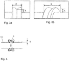
- this position of the sensor 5 different positions are approached along the sensor axis 7 in order to detect the weld seam geometry, preferably the weld seam width B and / or the K dimension K.
- Figure 3b shows a recording in which the sensor 5 is not opt at the optimal measuring position. M, that is, is positioned in the middle in front of the weld seam and thus the width B and the K dimension K are larger.
- Such recordings are recorded at at least three positions along the sensor axis 7, which is the minimum of recorded measurement data in order to determine or calculate the optimal measurement position.
- the known distance between the sensor 5 and the pipe 11 as well as the opening angle 9 of the lens and the two detected visible edges 2 of the weld seam 3 result in the weld seam width B or where the optimal measurement position opt. M can be recorded without distorting the width or the K dimension K, which is then used to evaluate the weld seam quality.
- Fig. 2 is shown when the sensor 5 is positioned in the optimal measuring position for recording the weld seam geometry, which is used to evaluate and evaluate the seam. It can be clearly seen that the sensor 5 or the optical axis 6 is centered on the weld seam, whereby parallax can be avoided, which is relevant for the evaluation and assessment of the weld seam quality.
- Fig. 4 shows a welded pipe 11 in which the weld seam 3 is shown in section in order to show which dimension besides the weld seam width B, namely the K dimension K, is also used to determine the optimal measurement position.
- This dimension K can be determined separately instead of the width B, but also in combination.
- Fig. 5 shows diagrams in which the determined measuring points for determining the optimal measuring position are shown as crosses. These were recorded during the approach to the different positions along the sensor axis, with which the optimal measurement position opt. M was preferably determined on the basis of an algorithm.
- the vertical axis B / K shows the measured dimension of the width of the weld seam B or the K dimension K of the weld seam and the horizontal axis the corresponding position x of the sensor on the sensor axis or the angle setting on the sensor axis.
- the optimal measuring position is opt.
- M can also be defined by the intersection of two straight lines that can be determined on the basis of the measuring points.
- the method is represented by means of a polynomial that does not run exactly through the measuring points but approximately through the measuring points.
- a determined measuring point is lower than the lowest point of the polynomial curve.
- the deeper individual point is preferably opted as the optimal measuring point.
- M used where in Fig. 5 in the second diagram the lowest point is on the curve and the individual point is arranged slightly higher. The last diagram again shows a polynomial curve that runs exactly through the measuring points.
- the device 1 according to the invention is shown three-dimensionally, being shown here independently of a pipe.
- the device 1 has a carrier device 8 on which a drive 10 is arranged and which has a sensor axis 7 for precise positioning of the sensor 5.
- the sensor 5 is preferably designed as a camera with a corresponding standard lens here, wherein or a telecentric lens can be used, but the arrangement of the sensor axis and the drive is then slightly changed.
Description
Die Erfindung betrifft ein Verfahren und eine Vorrichtung zur Erkennung einer Schweissnahtgeometrie einer Kunststoffstumpfschweissnaht zwischen Rohrleitungskomponenten vorzugsweise Kunststoffrohren, wobei die Vorrichtung eine Steuerung, einen optischen Sensor und eine Trägervorrichtung enthält, wobei die Trägervorrichtung einen Antrieb und eine Sensorachse zur Positionierung des Sensors aufweist, wobei der Antrieb eine Positionserkennung aufweist und mit einer Steuerung verbunden ist.The invention relates to a method and a device for detecting a weld seam geometry of a plastic butt weld seam between pipeline components, preferably plastic pipes, the device containing a controller, an optical sensor and a carrier device, the carrier device having a drive and a sensor axis for positioning the sensor, the drive has a position detection and is connected to a controller.
Eine Überprüfung einer Stumpfschweissung dient der Qualitätssicherung der Schweissung. Es spielt keine Rolle mit welchem Verfahren die Rohre bzw. Fittings stumpfgeschweisst wurden, sei es mittels berührungslosem IR-Schweissverfahrens, mittels des klassischen Stumpfschweissverfahrens durch Berühren des Heizspiegels oder eines anderen Verfahrens. Entsprechend den zu verschweissenden Rohren bzw. Fittings, das heisst, ihren Abmassen, deren Kunststoff, der Schweisstechnologie die angewandt wird, usw. hat eine Schweissnaht eine gewisse Form bzw. Grösse aufzuweisen, die optisch überprüfbar ist. Entsprechend dazu existieren Richtlinien bzw. Normen, welche genau definieren wie eine Naht aussehen muss bzw. wie die zulässigen Abmasse in Bezug auf die Rohr- bzw. Fitting- und Schweisseigenschaften sein müssen, damit sie den Anforderungen entspricht. Bisher wurde meist eine manuelle optische Beurteilung durch eine zuständige Fachperson durchgeführt, die anhand der ihr bekannten Normen und Richtlinien die entstandene Schweissnaht vergleicht und beurteilt.A check of a butt weld serves to ensure the quality of the weld. It does not matter which method the pipes or fittings were butt-welded, be it using the non-contact IR welding process, the classic butt welding process by touching the heating mirror or another process. According to the pipes or fittings to be welded, that is, their dimensions, their plastic, the welding technology used, etc., a weld seam has a certain shape or size that can be visually checked. Correspondingly, there are guidelines or standards that precisely define how a seam must look or what the permissible dimensions must be in relation to the pipe, fitting and welding properties so that it meets the requirements. So far, a manual visual assessment has usually been carried out by a competent specialist who compares and assesses the weld seam based on the standards and guidelines known to them.
Nachteilig hierbei ist, dass Beurteilungen durch eine Fachperson sehr zeitintensiv und somit sehr teuer sind. Zudem ist eine solche Beurteilung auch nicht konstant gleich, da der menschliche Faktor eine wesentliche Rolle spielt und die Überprüfung nicht immer durch dieselbe Fachperson stattfindet.The disadvantage here is that assessments by a specialist are very time-consuming and therefore very expensive. In addition, such an assessment is not always the same, since the human factor plays an essential role and the review is not always carried out by the same specialist.
Die
Nachteilig an dieser Prüfung ist der hohe Aufwand da eine derartige Prüfung sehr zeitintensiv ist, da die Platzierung der Ultraschallsensoren bzw. der Schweissnaht gegenüber der Ultraschallsensoren sehr genau erfolgen muss, was eine hohe Einrichtzeit erfordert.The disadvantage of this test is the high level of effort, since such a test is very time-consuming, since the ultrasonic sensors or the weld seam must be positioned very precisely in relation to the ultrasonic sensors, which requires a long setup time.
Die
Die
Die
Nachteilig hierbei ist, dass die Überprüfung nur direkt nach der Verschweissung stattfinden und nicht in einer separaten ev. späteren Prüfung erfolgen kann, da ein nachträgliches Einspannen in die Vorrichtung und ein entsprechendes Ausrichten kaum möglich ist.The disadvantage here is that the check only takes place directly after the welding and cannot be carried out in a separate, possibly later check, since subsequent clamping in the device and corresponding alignment is hardly possible.
Es ist Aufgabe der Erfindung ein Verfahren und eine damit verbundene Vorrichtung vorzuschlagen, welches ein schnelles und einfaches Durchführen einer optischen Überprüfung einer Stumpfschweissnaht zulässt, indem eine genaue Positionierung der Schweissnaht zum Sensor vermieden werden kann.It is the object of the invention to propose a method and a device connected to it, which allows a quick and easy implementation of an optical check of a butt weld, in that an exact positioning of the weld to the sensor can be avoided.
Diese Aufgabe wird erfindungsgemäss dadurch gelöst, dass das Verfahren zur Erkennung einer Schweissnahtgeometrie einer Kunststoffstumpfschweissnaht zwischen Rohrleitungskomponenten vorzugsweise Kunststoffrohren folgende Schritte beinhaltet:
- grobes, manuelles Positionieren eines optischen Sensors gegenüber einer Stumpfschweissnaht zwischen Rohrleitungskomponenten vorzugsweise Kunststoffrohren, vorzugsweise am Rohraussendurchmesser, wobei die Sensorausrichtung annähernd rechtwinklig zur Rohrmittelachse erfolgt,
- automatisches bzw. autonomes Anfahren des Sensors von Messpositionen entlang oder um eine Sensorachse ,
- erfassen der sichtbaren Schweissnahtgeometrie bzw. der Daten mittels Sensor in jeder angefahrenen Messposition,
- ermitteln der optimalen Messposition durch die erfassten Daten vorzugsweise mittels eines Algorithmus,
- automatisches bzw. autonomes Anfahren des Sensors der optimalen Messposition entlang oder um die Sensorachse,
- erfassen der Schweissnahtgeometrie zur Bestimmung der Qualität der Schweissnaht,
- Auswerten und Bewerten der Messung der erfassten Schweissnahtgeometrie an optimierter Messposition.
- coarse, manual positioning of an optical sensor opposite a butt weld seam between pipeline components, preferably plastic pipes, preferably on the Outer pipe diameter, whereby the sensor is aligned approximately at right angles to the central pipe axis,
- automatic or autonomous approach of the sensor from measuring positions along or around a sensor axis,
- capture of the visible weld seam geometry or the data by means of a sensor in each approached measuring position,
- determine the optimal measurement position through the recorded data, preferably by means of an algorithm,
- automatic or autonomous approach of the sensor to the optimal measuring position along or around the sensor axis,
- recording the weld seam geometry to determine the quality of the weld seam,
- Evaluation and evaluation of the measurement of the recorded weld seam geometry at an optimized measurement position.
Ein optischer Sensor wird grob, manuell positioniert gegenüber einer Stumpfschweissnaht die zwischen den verschweissten Rohrleitungskomponenten vorzugsweise Kunststoffrohren verläuft. Vorzugsweise wird der optische Sensor direkt am Rohraussendurchmesser angeordnet, beispielsweise mittels eines Befestigungsrings oder einem sonstigen einfachen Befestigungsmittel. Die Sensorausrichtung ist annähernd rechtwinklig zur Rohrachse ausgerichtet, wobei eine leichte Verschiebung durchaus vom Sensor aufgenommen bzw. selbständig korrigiert wird.An optical sensor is roughly, manually positioned opposite a butt weld that runs between the welded pipe components, preferably plastic pipes. The optical sensor is preferably arranged directly on the outside diameter of the pipe, for example by means of a fastening ring or some other simple fastening means. The sensor alignment is approximately at right angles to the pipe axis, with a slight shift being taken up by the sensor or corrected automatically.
Der Sensor fährt automatisch bzw. autonom entlang bzw. um eine Sensorachse Messpositionen an, an denen er die Schweissnaht bzw. die Schweissnahtbreite und oder das K-Mass erfasst.The sensor moves automatically or autonomously along or around a sensor axis to measuring positions at which it detects the weld seam or the weld seam width and / or the K dimension.
An den Messpositionen, die vorzugsweise über die Steuerung definiert sind, erfasst der Sensor die sichtbare Schweissnahtgeometrie. Durch die grobe, manuelle Positionierung des Sensors gegenüber der Schweissnaht muss der Sensor um eine genaue Auswertung über die Qualität bzw. die Schweissnahtgeometrie zu ermöglichen zuerst die optimale Messposition der Schweissnaht finden bei der der Sensor direkt bzw. senkrecht auf die Schweissnaht gerichtet ist ohne seitliche Verschiebung bzw. auch ohne Schräglage des Sensors zur Schweissnaht. Dazu werden mindestens drei Messpositionen angefahren und die entsprechenden Schweissnahtgeometrien erfasst, vorzugsweise jeweils die Schweissnahtbreite und/oder das K-Mass.The sensor detects the visible weld seam geometry at the measuring positions, which are preferably defined via the control. Due to the coarse, manual positioning of the sensor in relation to the weld seam, the sensor must first find the optimal measurement position of the weld seam in order to enable an accurate evaluation of the quality or the weld seam geometry The sensor is directed directly or perpendicularly to the weld seam without lateral displacement or even without the sensor being inclined relative to the weld seam. For this purpose, at least three measurement positions are approached and the corresponding weld seam geometries are recorded, preferably the weld seam width and / or the K dimension in each case.
Aus den zuvor erfassten Daten wird dann die optimale Messposition vorzugsweise mittels eines Algorithmus ermittelt. Die optimale Messposition ist an der Stelle an der die Schweissnahtbreite oder auch das K-Mass am geringsten ist da bei der frontalen Draufsicht auf die Schweissnaht keine Verbreiterung durch Parallaxe entsteht. Wobei es ausreicht wenn nur die Breiten oder die K-Masse erfasst werden um die optimale Messposition zu ermitteln.
Aufgrund der ermittelten, optimalen Messposition fährt der Sensor entlang oder um die Sensorachse in diese optimale Messposition.The optimal measurement position is then determined from the previously acquired data, preferably by means of an algorithm. The optimum measuring position is at the point where the weld seam width or the K dimension is the smallest, since there is no widening due to parallax when viewed from the front on the weld seam. Whereby it is sufficient if only the widths or the K-mass are recorded in order to determine the optimal measurement position.
Based on the determined, optimal measuring position, the sensor moves along or around the sensor axis into this optimal measuring position.
Dort erfasst er wiederum die Schweissnahtgeometrie, welche dann der Auswertung und Bewertung der Qualität und der Masshaltigkeit der Schweissnaht dient. Vorzugsweise wird die Auswertung und Bewertung mittels der Steuerung durchgeführt und beruht auf vordefinierten Werte aufgrund derer die aufgenommene Schweissnahtgeometrie verglichen wird.There it in turn records the weld seam geometry, which is then used to evaluate and assess the quality and dimensional accuracy of the weld seam. The evaluation and assessment is preferably carried out by means of the control and is based on predefined values on the basis of which the recorded weld seam geometry is compared.
Vorteilhaft ist es, wenn während des automatischen bzw. autonomen Anfahrens des Sensors der Messpositionen entlang oder um die Sensorachse mindestens drei Messpositionen zum Erfassen der sichtbaren Schweissnahtgeometrie angefahren werden. Dadurch kann die optimale Messposition vorzugsweise mittels Algorithmus ermittelt werden. Selbstverständlich sind auch mehr Messpositionen entlang oder um die Sensorachse möglich. Bevorzugterweise werden jeweils die beiden Extrempositionen jeweils ganz aussen liegend an der Sensorachse angefahren und die dortige Schweissnahtgeometrie vorzugsweise die Schweissnahtbreite und/oder das K-Mass erfasst um in die Berechnung der optimalen Messposition einzufliessen, wie auch die äusseren Extrempositionen beim Schwenken des Sensors um die Sensorachse angefahren werden.It is advantageous if, during the automatic or autonomous approach of the sensor to the measurement positions along or around the sensor axis, at least three measurement positions are approached to detect the visible weld seam geometry. As a result, the optimal measurement position can be determined, preferably by means of an algorithm. Of course, more measuring positions along or around the sensor axis are also possible. The two extreme positions are preferably approached on the very outside of the sensor axis and the weld seam geometry there preferably records the weld seam width and / or the K dimension in order to flow into the calculation of the optimal measurement position, as well as the outer extreme positions when the sensor is pivoted around the sensor axis be approached.
Als vorteilhaft hat sich gezeigt, dass die Schweissnahtbreite und/oder das K-Mass mittels Sensor in jeder angefahrenen Messposition erfasst werden. Diese Messdaten werden dann zur Ermittlung der optimalen Messposition genutzt, da die optimale Messposition ausschlaggebend für die Ermittlung der Schweissnahtgeometrie zur Qualitätsbestimmung ist, da nur in dieser Position in der der Sensor geradlinig bzw. senkrecht auf die Schweissnaht gerichtet ist eine korrekte Aufnahme der Schweissnaht ohne Parallaxe bzw. Bildverzerrung erfasst wird.It has been shown to be advantageous that the weld seam width and / or the K dimension are recorded by means of a sensor in each measurement position approached. These measurement data are then used to determine the optimum measurement position, since the optimum measurement position is decisive for determining the weld seam geometry for quality determination, since correct recording of the weld seam without parallax is only possible in this position in which the sensor is directed straight or perpendicular to the weld seam or image distortion is detected.
Gemäss einer bevorzugten Ausführungsform ermittelt der Algorithmus die optimale Messposition durch die erfassten sichtbaren Schweissnahtgeometrien bzw. Messdaten, insbesondere durch die erfassten Schweissnahtbreiten und/oder die K-Masse, wobei die optimale Messposition die Position ist an der die geringste Schweissnahtbreite und/oder das geringste K-Mass vorliegt da keine Bildverzerrung herrscht. An der optimalen Messposition ist der Sensor mittig bzw. annähernd senkrecht auf die Schweissnaht gerichtet was eine Bildverzerrung verhindert und eine optimale Aufnahme der Schweissnahtgeometrie zur Qualitätskontrolle zulässt. Vorzugsweise wird der Algorithmus zur Ermittlung der optimalen Messposition aufgrund der erfassten Daten durch ein Polynom bestimmt. Das Polynom kann exakt durch die ermittelten Messdaten wie auch annähernd durch den Bereich der Messdaten verlaufen.
Die optimale Messposition wird vorzugsweise durch den tiefsten Punkt des Polynoms gebildet oder durch einen Messpunkt, der aufgrund einer annähernden Polynombildung tiefer liegt als der tiefste Punkt des Polynoms bzw. der einen tieferen Wert aufweist.According to a preferred embodiment, the algorithm determines the optimal measurement position from the recorded visible weld seam geometries or measurement data, in particular from the recorded weld seam widths and / or the K dimensions, the optimal measurement position being the position at which the smallest weld seam width and / or the smallest K -Mass is available because there is no image distortion. At the optimal measuring position, the sensor is centered or almost perpendicular to the weld seam, which prevents image distortion and allows optimal recording of the weld seam geometry for quality control. The algorithm for determining the optimal measurement position is preferably determined by a polynomial on the basis of the acquired data. The polynomial can run exactly through the determined measurement data as well as approximately through the range of the measurement data.
The optimal measuring position is preferably formed by the lowest point of the polynomial or by a measuring point which, due to an approximate polynomial formation, is lower than the lowest point of the polynomial or which has a lower value.
Es ist vorteilhaft wenn das automatische Anfahren des Sensors von Messpositionen entlang einer Sensorachse verläuft die parallel zur Rohrachse ausgerichtet ist. Durch den bekannten Abstand zwischen Sensor und dem Rohr sowie dem Öffnungswinkel der zwischen der einen Kante der Schweissnaht und dem Sensor, welches eine fiktive Gerade bildet, und der anderen Kante und dem Sensor, welches eine weitere fiktive Gerade bildet, vorliegt, kann somit der Versatz entlang der Rohrachse des Sensors zur Schweissnaht bzw. zur optimalen Messposition somit zur Mitte der Schweissnaht ermittelt werden. Jedoch werden dazu mindestens drei Messpunkte benötigt.It is advantageous if the automatic approach of the sensor to measuring positions runs along a sensor axis which is aligned parallel to the pipe axis. Due to the known distance between the sensor and the pipe and the opening angle between the one edge of the weld seam and the sensor, which forms a fictitious straight line, and the other edge and the sensor, which forms a further fictitious straight line, the offset can thus along the pipe axis of the sensor to the weld seam or to the optimal measurement position thus to the center of the weld seam. However, at least three measuring points are required for this.
Eine alternative Ausgestaltung des Verfahrens besteht darin, dass die Sensorachse annähernd senkrecht zur Rohrmittelachs verläuft, wobei der Sensor an der Sensorachse schwenkbar angeordnet ist. Vorzugsweise ist der Sensor als Kamera ausgebildet die ein telezentrisches Objektiv aufweist, welche ein zylindrisch verlaufendes Blickfeld aufweist. Bei dieser Art von Objektiv liegt der Unterschied zum Standardobjektiv welches ein kegelförmiges Blickfeld aufweist darin, dass dieses ein zylindrisch verlaufendes Blickfeld aufweist. Dadurch muss hier die Schweissnaht nicht zwingend in der Mitte des Blickfelds angeordnet sein wie bei einem Standardobjektiv, vielmehr muss das Objektiv senkrecht auf die Schweissnaht gerichtet sein bzw. die optische Achse des Objektivs muss rechtwinklig auf die Rohrmittelachse gerichtet sein.An alternative embodiment of the method consists in that the sensor axis runs approximately perpendicular to the pipe center axis, the sensor being arranged pivotably on the sensor axis. The sensor is preferably designed as a camera which has a telecentric lens which has a cylindrical field of view. With this type of lens, the difference to the standard lens, which has a conical field of view, is that it has a cylindrical field of view. As a result, the weld seam does not necessarily have to be arranged in the center of the field of view as with a standard lens, but rather the lens must be directed perpendicular to the weld seam or the optical axis of the lens must be directed at right angles to the tube center axis.
Diese Aufgabe wird erfindungsgemäss dadurch gelöst, dass die Sensorachse sich parallel oder senkrecht zur Rohrleitungsachse erstreckt und der Sensor entlang oder um die Sensorachse verfahrbar oder schwenkbar ist wobei die Steuerung die Auswertung und Bewertung der aufgenommenen Schweissnahtgeometrie aufgrund vordefinierter Werte durchführt.This object is achieved according to the invention in that the sensor axis extends parallel or perpendicular to the pipe axis and the sensor can be moved or pivoted along or around the sensor axis, the control system evaluating and evaluating the recorded weld seam geometry based on predefined values.
Die erfindungsgemässe Vorrichtung zur Durchführung des Verfahrens zur Erkennung einer Schweissnahtgeometrie einer Kunststoffstumpfschweissnaht zwischen Rohrleitungskomponenten vorzugsweise Kunststoffrohren ist im Anspruch 8 definiert. Die Vorrichtung weist einen optischen Sensor und eine Trägervorrichtung auf, wobei die Trägervorrichtung einen Antrieb und eine Sensorachse zur Positionierung des Sensors enthält. Die Sensorachse ist parallel oder senkrecht zur Rohrleitungsachse ausgerichtet und der Sensor ist entlang oder um die Sensorachse verfahrbar oder schwenkbar bzw. drehbar.The device according to the invention for carrying out the method for recognizing a weld seam geometry of a plastic butt weld seam between pipeline components, preferably plastic pipes, is defined in
Als vorteilhaft hat sich gezeigt, wenn die erfindungsgemässe Vorrichtung direkt am Rohraussendurchmesser befestigt ist, beispielsweise mit einem Band oder einem Ring an dem die Vorrichtung befestigt ist und der am Rohr angeordnet wird, wobei auch ein unabhängig vom Rohr vorgesehener Support für die Vorrichtung denkbar ist in den das Rohr eingelegt werden kann.It has been shown to be advantageous if the device according to the invention is fastened directly to the pipe outer diameter, for example with a band or a ring to which the device is fastened and which is arranged on the pipe, whereby a support for the device provided independently of the pipe is also conceivable in which the pipe can be inserted.
Als vorteilhaft hat sich gezeigt, wenn der Sensor als Kamera ausgebildet ist und ein normales bzw. Standardobjektiv oder ein telezentrisches Objektiv aufweist. Bei der Verwendung eines telezentrischen Objektives ist es von Vorteil wenn eine rechtwinklig bzw. senkrecht zur Rohrmittelachse verlaufende Sensorachse verwendet wird um welche der Sensor bzw. die Kamera mit telezentrischem Objektiv geschwenkt wird, da ein telezentrisches Objektiv nur ein geradverlaufendes bzw. zylindrisches Blickfeld aufweist und somit die Kamera bzw. das Objektiv sich schwenkbar gegenüber der Schweissnaht ausrichten muss um die optimale Messposition zu erlangen und Bildverzerrungen zu vermeiden. Hingegen bei einem Standardobjektiv welches ein kegelförmiges Blickfeld aufweist ist es wichtig um Bildverzerrungen zu vermeiden, dass die Schweissnaht in der Mitte des Blickfelds ist, weshalb die Ausrichtung über eine parallel zur Rohrleitung verlaufende Sensorachse erfolgt.It has been shown to be advantageous if the sensor is designed as a camera and has a normal or standard lens or a telecentric lens. When using a telecentric lens, it is advantageous if a Sensor axis running at right angles or perpendicular to the pipe center axis is used around which the sensor or the camera with telecentric lens is pivoted, since a telecentric lens only has a straight or cylindrical field of view and thus the camera or lens can be pivoted relative to the weld seam must in order to achieve the optimal measuring position and to avoid image distortion. In contrast, with a standard lens which has a conical field of view, it is important to avoid image distortion that the weld seam is in the center of the field of view, which is why the alignment takes place via a sensor axis running parallel to the pipeline.
Es ist vorteilhaft wenn der Antrieb als Schrittmotor mit eine Spindel ausgebildet ist, wobei auch Linearmotoren denkbar sind. Der komplette Vorgang zur Erfassung der Schweissnahtgeometrie und zu dessen Auswertung dauert wenige Sekunden, vorzugsweise zwischen 1 und 20 Sekunden, wobei speziell bevorzugt eine Durchführung in 1 und 12 Sekunden erfolgt.It is advantageous if the drive is designed as a stepper motor with a spindle, linear motors also being conceivable. The complete process for recording the weld seam geometry and for evaluating it takes a few seconds, preferably between 1 and 20 seconds, with an implementation taking place in 1 and 12 seconds, with particular preference.
Der Antrieb weist vorzugsweise eine Positionserkennung auf, die vorzugsweise mit einer Steuerung verbunden ist. Dadurch kann ermittelt werden an welcher Stelle der Sensor steht und mittels den Berechnungen und den ermittelten Messdaten kann die optimale Messposition, die auch über die Positionserkennung abläuft, angefahren werden.The drive preferably has position detection, which is preferably connected to a controller. This makes it possible to determine where the sensor is located and, by means of the calculations and the determined measurement data, the optimum measurement position, which also takes place via the position detection, can be approached.
Alle Ausgestaltungmöglichkeiten sind untereinander frei kombinierbar, sowie die Verfahrensmerkmale auch mit den Vorrichtungsmerkmalen kombinierbar sind.All design options can be freely combined with one another, and the process features can also be combined with the device features.
Ein Ausführungsbeispiel der Erfindung wird anhand der Figuren beschrieben, wobei sich die Erfindung nicht nur auf das Ausführungsbeispiel beschränkt. Es zeigen:
- Fig. 1
- eine schematische Darstellung der Anordnungen der erfindungsgemässen Vorrichtung zur Durchführung des erfindungsgemässen Verfahrens während des Anfahrens von Messpositionen mit Standardobjektiv,
- Fig. 2
- eine schematische Darstellung der Anordnungen der erfindungsgemässen Vorrichtung zur Durchführung des erfindungsgemässen Verfahrens in optimaler Messpositionen mit Standardobjektiv,
- Fig. 3a
- eine Aufnahme des Sensors in optimaler Messposition
- Fig. 3b
- eine Aufnahme des Sensors in einer Messposition zur Ermittlung der optimalen Messposition,
- Fig. 4
- einen Längsschnitt durch ein Rohr mit einer Schweissnaht,
- Fig. 5
- schematische Darstellung der erfassten Messposition und dadurch ermittelten optimalen Messposition,
- Fig. 6
- eine dreidimensionale Ansicht einer erfindungsgemässen Vorrichtung.
- Fig. 7
- eine schematische Darstellung der Anordnungen der erfindungsgemässen Vorrichtung zur Durchführung des erfindungsgemässen Verfahrens während des Anfahrens von Messpositionen mit telezentrischem Objektiv und ,
- Fig. 8
- eine schematische Darstellung der Anordnungen der erfindungsgemässen Vorrichtung zur Durchführung des erfindungsgemässen Verfahrens in optimaler Messpositionen mit telezentrischem Objektiv.
- Fig. 1
- a schematic representation of the arrangements of the device according to the invention for carrying out the method according to the invention while moving to measuring positions with a standard objective,
- Fig. 2
- a schematic representation of the arrangements of the inventive device for performing the method according to the invention in optimal measuring positions with standard objective,
- Fig. 3a
- a recording of the sensor in the optimal measuring position
- Figure 3b
- a recording of the sensor in a measuring position to determine the optimal measuring position,
- Fig. 4
- a longitudinal section through a pipe with a weld seam,
- Fig. 5
- Schematic representation of the recorded measuring position and the resulting optimal measuring position,
- Fig. 6
- a three-dimensional view of a device according to the invention.
- Fig. 7
- a schematic representation of the arrangements of the device according to the invention for carrying out the method according to the invention while moving to measuring positions with a telecentric lens and,
- Fig. 8
- a schematic representation of the arrangements of the device according to the invention for carrying out the method according to the invention in optimal measuring positions with a telecentric lens.
Die in
In
Im ersten Diagramm ist erkennbar, dass die optimale Messposition opt. M auch durch den Schnittpunkt zweier Geraden definiert werden kann, die aufgrund der Messpunkte ermittelt werden können.
Alternativ ist die Methode mittels eine Polynoms dargestellt, der nicht exakt durch die Messpunkte verläuft sondern annähernd durch die Messpunkte. Dadurch kann es vorkommen, dass ein ermittelter Messpunkt tiefer liegt als der tiefste Punkt des Polynomverlaufs. In einem solchen Fall wird vorzugsweise der tiefere einzelne Punkt als optimaler Messpunkt opt. M verwendet, wobei in
Alternatively, the method is represented by means of a polynomial that does not run exactly through the measuring points but approximately through the measuring points. As a result, it can happen that a determined measuring point is lower than the lowest point of the polynomial curve. In such a case, the deeper individual point is preferably opted as the optimal measuring point. M used, where in
In
Die in
- 11
- Vorrichtung zur Erkennung einer Schweissnahtgeometrie einer KunststoffstumpfschweissnahtDevice for recognizing a weld seam geometry of a plastic butt weld seam
- 22
- Kante SchweissnahtEdge weld seam
- 33
- SchweissnahtWeld
- 44th
- RohrmittelachsePipe center axis
- 55
- Sensorsensor
- 66th
- Optische Achse des Objektives, mittig zur Schweissnaht bei Standardobjektiv, rechtwinklig zur Rohrmittelachse bei telezentrischem Objektiv (opt. Messpostion)Optical axis of the lens, in the middle of the weld seam with standard lenses, at right angles to the tube center axis with telecentric lenses (opt. Measuring position)
- 77th
- SensorachseSensor axis
- 88th
- TrägervorrichtungCarrier device
- 99
- ÖffnungswinkelOpening angle
- 1010
- Antriebdrive
- 1111
- Rohrpipe
- KK
- gemessenes K-Massmeasured K-measure
- BB.
- gemessene Schweissnahtbreitemeasured weld seam width
- Opt. MOpt. M
- optimale Messpositionoptimal measuring position
- XX
- Position auf SensorachsePosition on the sensor axis
Claims (10)
- Method for sensing a weld seam geometry of a plastic butt weld seam (3) between pipeline components, preferably plastic pipes (11), including the following steps:• rough manual positioning of an optical sensor (5) in relation to a butt weld seam (3) between pipeline components, preferably plastic pipes, preferably at the pipe external diameter, wherein the sensor is aligned approximately perpendicularly to the pipe centre axis (4),• automatic approaching by the sensor of measurement positions along or around a sensor axis (7),• acquiring the visible weld seam geometry and/or the data by means of the sensor (5) in each approached measurement position,• determining the optimum measurement position (opt. M) by way of the acquired data, preferably by means of an algorithm,• automatic approaching by the sensor (5) of the optimum measurement position (opt. M) along or around the sensor axis (7),• acquiring the weld seam geometry to determine the quality of the weld seam,• analyzing and judging the measurement of the acquired weld seam geometry at the optimized measurement position.
- Method according to Claim 1, characterized in that, during the automatic approaching by the sensor of the measurement positions along or around the sensor axis (7), at least three measurement positions are approached to acquire the visible weld seam geometry.
- Method according to one of Claims 1 or 2, characterized in that the weld seam width (B) and/or the K dimension (K) are acquired by means of the sensor (5) in each approached measurement position
- Method according to one of Claims 1 to 3, characterized in that the algorithm determines the optimum measurement position (opt. M) by way of the acquired visible weld seam geometries, in particular by way of the acquired weld seam widths (B) and/or the K dimensions (K), wherein the optimum measurement position (opt. M) is the position at which the smallest weld seam width (B) and/or the smallest K dimension (K) and no image distortion is present.
- Method according to one of Claims 1 to 4, characterized in that an algorithm for determining the optimum measurement position on the basis of the acquired data is defined by a polynomial.
- Method according to one of the preceding claims, characterized in that the automatic approaching by the sensor of measurement positions extends along a sensor axis which is aligned parallel to the pipe axis.
- Method according to one of the preceding claims, characterized in that the automatic approaching by the sensor (5) of measurement positions extends around a sensor axis (7), wherein the sensor axis (7) is used as the rotational axis or pivot point of the sensor (5) and extends approximately perpendicularly to the pipe centre axis (4).
- Device configured for carrying out the method according to any one of Claims 1 to 7 containing a controller, an optical sensor (5) and a carrier device (8), wherein the carrier device (8) has a drive (10) and a sensor axis (7) for positioning of the sensor (5), wherein the drive (10) has a position sensing unit and is connected to a controller, characterized in that the sensor axis (7) extends parallel or perpendicularly to the pipeline axis (4) and the sensor (5) is movable along or rotatable and/or pivotable along or around the sensor axis (7), wherein the controller carries out the analysis and judgement of the recorded weld seam geometry on the basis of predefined values.
- Device according to Claim 8, characterized in that the sensor (5) is designed as a camera and has a normal or standard objective lens or a telecentric objective lens.
- Device according to Claim 8, characterized in that the drive (10) is designed as a stepping motor having a spindle.
Priority Applications (4)
| Application Number | Priority Date | Filing Date | Title |
|---|---|---|---|
| EP18165805.5A EP3550256B1 (en) | 2018-04-05 | 2018-04-05 | Detection of a weld seam geometry |
| US16/293,713 US10940564B2 (en) | 2018-04-05 | 2019-03-06 | Method for detecting weld seam geometry |
| KR1020190034428A KR102652513B1 (en) | 2018-04-05 | 2019-03-26 | Sensing of a weld seam geometry |
| CN201910271298.2A CN110345881B (en) | 2018-04-05 | 2019-04-04 | Sensing weld geometry |
Applications Claiming Priority (1)
| Application Number | Priority Date | Filing Date | Title |
|---|---|---|---|
| EP18165805.5A EP3550256B1 (en) | 2018-04-05 | 2018-04-05 | Detection of a weld seam geometry |
Publications (2)
| Publication Number | Publication Date |
|---|---|
| EP3550256A1 EP3550256A1 (en) | 2019-10-09 |
| EP3550256B1 true EP3550256B1 (en) | 2021-03-10 |
Family
ID=61965694
Family Applications (1)
| Application Number | Title | Priority Date | Filing Date |
|---|---|---|---|
| EP18165805.5A Active EP3550256B1 (en) | 2018-04-05 | 2018-04-05 | Detection of a weld seam geometry |
Country Status (4)
| Country | Link |
|---|---|
| US (1) | US10940564B2 (en) |
| EP (1) | EP3550256B1 (en) |
| KR (1) | KR102652513B1 (en) |
| CN (1) | CN110345881B (en) |
Families Citing this family (8)
| Publication number | Priority date | Publication date | Assignee | Title |
|---|---|---|---|---|
| JP6709638B2 (en) * | 2016-03-10 | 2020-06-17 | 日立造船株式会社 | Welding method of steel pipe and joint in steel pipe structure |
| FI3667148T3 (en) | 2018-12-13 | 2023-01-31 | Length compensator | |
| KR102594309B1 (en) | 2020-04-20 | 2023-10-27 | (주)아그루코리아 | Welding bead inspection apparatus |
| KR102537856B1 (en) * | 2020-05-20 | 2023-05-31 | (주)아그루코리아 | Welding inspection method |
| CN111735393B (en) * | 2020-07-13 | 2021-11-19 | 西安交通大学 | Device and method for synchronously measuring linear displacement and straightness of guide rail in situ |
| CN113504239B (en) * | 2021-06-10 | 2022-12-02 | 上海西信信息科技股份有限公司 | Quality control data analysis method |
| EP4194184A1 (en) | 2021-12-07 | 2023-06-14 | Georg Fischer Rohrleitungssysteme AG | Welding assessment during the welding process |
| CN116295191B (en) * | 2023-05-22 | 2023-07-28 | 山东津岳环保设备有限公司 | Device for detecting axial offset of V-shaped girth weld of sealed tank and control method |
Family Cites Families (15)
| Publication number | Priority date | Publication date | Assignee | Title |
|---|---|---|---|---|
| CN1021028C (en) * | 1989-12-18 | 1993-06-02 | 天津市电视技术研究所 | Method and apparatus for torch head to track weld line automatically |
| US5168141A (en) * | 1991-06-14 | 1992-12-01 | General Electric Company | Vision guided laser welding |
| JP2000289115A (en) | 1999-04-06 | 2000-10-17 | Kubota Corp | Method for inspecting plastic pipe butt-welded part |
| AU2002246960A1 (en) * | 2001-01-09 | 2002-08-06 | Edison Welding Institute | Non-destructive butt weld inspection method |
| DE10151703B4 (en) * | 2001-10-19 | 2004-12-09 | OCé PRINTING SYSTEMS GMBH | Apparatus and method for sensing the nature of a layer of toner particles in a printer or copier |
| CN101629806B (en) * | 2009-06-22 | 2011-01-05 | 哈尔滨工程大学 | Nonlinear CCD 3D locating device combined with laser transmitter and locating method thereof |
| EP2523017A1 (en) * | 2011-05-13 | 2012-11-14 | Hexagon Technology Center GmbH | Calibration method for a device with scan functionality |
| CA2743016A1 (en) * | 2011-06-10 | 2012-12-10 | Hermary Opto Electronics Inc. | 3d machine vision scanning information extraction system |
| KR20130032425A (en) * | 2011-09-23 | 2013-04-02 | (주)에이디에스 테크놀로지 | Laser welder for recognizing image of laser welding edge using camera and method for aligning the same |
| US9402036B2 (en) * | 2011-10-17 | 2016-07-26 | Rudolph Technologies, Inc. | Scanning operation with concurrent focus and inspection |
| CA2906711C (en) * | 2013-03-15 | 2018-08-21 | Commercial Coating Services International, Llc | Pipe outer surface inspection apparatus |
| EP2963380B8 (en) * | 2014-07-04 | 2020-02-26 | Georg Fischer Rohrleitungssysteme AG | Contactless inspection for butt welding |
| CA2915855C (en) * | 2014-12-19 | 2019-04-16 | Institut National D'optique | Device for optical profilometry with conical light beams |
| CN105328304B (en) * | 2015-12-09 | 2017-05-31 | 山东中清智能科技股份有限公司 | Based on statistical weld seam starting point automatic localization method |
| US10769769B2 (en) * | 2016-07-01 | 2020-09-08 | Kla-Tencor Corporation | Dual mode inspector |
-
2018
- 2018-04-05 EP EP18165805.5A patent/EP3550256B1/en active Active
-
2019
- 2019-03-06 US US16/293,713 patent/US10940564B2/en active Active
- 2019-03-26 KR KR1020190034428A patent/KR102652513B1/en active IP Right Grant
- 2019-04-04 CN CN201910271298.2A patent/CN110345881B/en active Active
Non-Patent Citations (1)
| Title |
|---|
| None * |
Also Published As
| Publication number | Publication date |
|---|---|
| EP3550256A1 (en) | 2019-10-09 |
| KR102652513B1 (en) | 2024-03-28 |
| US20190308277A1 (en) | 2019-10-10 |
| US10940564B2 (en) | 2021-03-09 |
| KR20190116914A (en) | 2019-10-15 |
| CN110345881B (en) | 2024-02-06 |
| CN110345881A (en) | 2019-10-18 |
Similar Documents
| Publication | Publication Date | Title |
|---|---|---|
| EP3550256B1 (en) | Detection of a weld seam geometry | |
| EP2963380B1 (en) | Contactless inspection for butt welding | |
| DE102013109915B4 (en) | Method and device for checking an inspection system for detecting surface defects | |
| DE102007017747B4 (en) | Method and device for the optical measurement of external threads | |
| EP3225322B1 (en) | Method and bending machine for making a multi-dimensional curved bent component | |
| DE102011119658B4 (en) | Method and device for testing pipes | |
| EP2205933B1 (en) | Device for optically measuring and/or testing oblong products | |
| DE102016014564A1 (en) | Measuring device for monitoring a machining process using measurement information acquired at different measuring positions | |
| DE102010012858B4 (en) | Device and method for rotational alignment of a tube head relative to a tube body | |
| EP2590761B1 (en) | Rolling mill with device for determining the rolling or guiding gap of the roll stands or guide stands in a multi-stand rolling mill | |
| DE102012100639B4 (en) | Hardness tester and method for setting a hardness tester | |
| WO2007121953A1 (en) | Device for automatically applying or producing and monitoring a structure placed on a substrate with a determination of geometric dimensions and corresponding method therefor | |
| EP2062675B1 (en) | Method for determining a parameter for seam position regulation precision | |
| EP0507923A1 (en) | Process and device for the opto-electronic measurement of objects | |
| EP2745945A1 (en) | Method and apparatus for non-contact geometric measurement of an object to be measured | |
| EP3257656B1 (en) | Pipe end detection | |
| DE202015100339U1 (en) | folding device | |
| DE2642481C3 (en) | Method and device for aligning a US test facility | |
| WO2020083617A1 (en) | Method for testing a joint | |
| EP1075892B1 (en) | Method and measuring appartus for the on-line quality control of a roll or press seam weld of assembled sheets | |
| EP0056215B1 (en) | Method and apparatus for inspecting cast strips in a continuous casting machine | |
| DE102017010108A1 (en) | Device and method for detecting the current position of a welding wire supplied to a laser welding process | |
| DE19505832A1 (en) | Optical test facility for online evaluation of welds or soldered seams | |
| DE102018100500A1 (en) | Apparatus and method for testing rod-shaped articles of the tobacco processing industry | |
| EP2500615A1 (en) | Method for determining a tube diameter |
Legal Events
| Date | Code | Title | Description |
|---|---|---|---|
| PUAI | Public reference made under article 153(3) epc to a published international application that has entered the european phase |
Free format text: ORIGINAL CODE: 0009012 |
|
| STAA | Information on the status of an ep patent application or granted ep patent |
Free format text: STATUS: THE APPLICATION HAS BEEN PUBLISHED |
|
| AK | Designated contracting states |
Kind code of ref document: A1 Designated state(s): AL AT BE BG CH CY CZ DE DK EE ES FI FR GB GR HR HU IE IS IT LI LT LU LV MC MK MT NL NO PL PT RO RS SE SI SK SM TR |
|
| AX | Request for extension of the european patent |
Extension state: BA ME |
|
| STAA | Information on the status of an ep patent application or granted ep patent |
Free format text: STATUS: REQUEST FOR EXAMINATION WAS MADE |
|
| 17P | Request for examination filed |
Effective date: 20200325 |
|
| RBV | Designated contracting states (corrected) |
Designated state(s): AL AT BE BG CH CY CZ DE DK EE ES FI FR GB GR HR HU IE IS IT LI LT LU LV MC MK MT NL NO PL PT RO RS SE SI SK SM TR |
|
| STAA | Information on the status of an ep patent application or granted ep patent |
Free format text: STATUS: EXAMINATION IS IN PROGRESS |
|
| 17Q | First examination report despatched |
Effective date: 20200603 |
|
| GRAP | Despatch of communication of intention to grant a patent |
Free format text: ORIGINAL CODE: EPIDOSNIGR1 |
|
| STAA | Information on the status of an ep patent application or granted ep patent |
Free format text: STATUS: GRANT OF PATENT IS INTENDED |
|
| INTG | Intention to grant announced |
Effective date: 20201204 |
|
| STAA | Information on the status of an ep patent application or granted ep patent |
Free format text: STATUS: GRANT OF PATENT IS INTENDED |
|
| GRAS | Grant fee paid |
Free format text: ORIGINAL CODE: EPIDOSNIGR3 |
|
| GRAA | (expected) grant |
Free format text: ORIGINAL CODE: 0009210 |
|
| STAA | Information on the status of an ep patent application or granted ep patent |
Free format text: STATUS: THE PATENT HAS BEEN GRANTED |
|
| AK | Designated contracting states |
Kind code of ref document: B1 Designated state(s): AL AT BE BG CH CY CZ DE DK EE ES FI FR GB GR HR HU IE IS IT LI LT LU LV MC MK MT NL NO PL PT RO RS SE SI SK SM TR |
|
| REG | Reference to a national code |
Ref country code: GB Ref legal event code: FG4D Free format text: NOT ENGLISH |
|
| REG | Reference to a national code |
Ref country code: AT Ref legal event code: REF Ref document number: 1370291 Country of ref document: AT Kind code of ref document: T Effective date: 20210315 Ref country code: CH Ref legal event code: NV Representative=s name: GEORG FISCHER AG, CH Ref country code: CH Ref legal event code: EP |
|
| REG | Reference to a national code |
Ref country code: IE Ref legal event code: FG4D Free format text: LANGUAGE OF EP DOCUMENT: GERMAN |
|
| REG | Reference to a national code |
Ref country code: DE Ref legal event code: R096 Ref document number: 502018004201 Country of ref document: DE |
|
| REG | Reference to a national code |
Ref country code: LT Ref legal event code: MG9D |
|
| PG25 | Lapsed in a contracting state [announced via postgrant information from national office to epo] |
Ref country code: NO Free format text: LAPSE BECAUSE OF FAILURE TO SUBMIT A TRANSLATION OF THE DESCRIPTION OR TO PAY THE FEE WITHIN THE PRESCRIBED TIME-LIMIT Effective date: 20210610 Ref country code: LT Free format text: LAPSE BECAUSE OF FAILURE TO SUBMIT A TRANSLATION OF THE DESCRIPTION OR TO PAY THE FEE WITHIN THE PRESCRIBED TIME-LIMIT Effective date: 20210310 Ref country code: FI Free format text: LAPSE BECAUSE OF FAILURE TO SUBMIT A TRANSLATION OF THE DESCRIPTION OR TO PAY THE FEE WITHIN THE PRESCRIBED TIME-LIMIT Effective date: 20210310 Ref country code: GR Free format text: LAPSE BECAUSE OF FAILURE TO SUBMIT A TRANSLATION OF THE DESCRIPTION OR TO PAY THE FEE WITHIN THE PRESCRIBED TIME-LIMIT Effective date: 20210611 Ref country code: HR Free format text: LAPSE BECAUSE OF FAILURE TO SUBMIT A TRANSLATION OF THE DESCRIPTION OR TO PAY THE FEE WITHIN THE PRESCRIBED TIME-LIMIT Effective date: 20210310 Ref country code: BG Free format text: LAPSE BECAUSE OF FAILURE TO SUBMIT A TRANSLATION OF THE DESCRIPTION OR TO PAY THE FEE WITHIN THE PRESCRIBED TIME-LIMIT Effective date: 20210610 |
|
| REG | Reference to a national code |
Ref country code: NL Ref legal event code: MP Effective date: 20210310 |
|
| PG25 | Lapsed in a contracting state [announced via postgrant information from national office to epo] |
Ref country code: RS Free format text: LAPSE BECAUSE OF FAILURE TO SUBMIT A TRANSLATION OF THE DESCRIPTION OR TO PAY THE FEE WITHIN THE PRESCRIBED TIME-LIMIT Effective date: 20210310 Ref country code: LV Free format text: LAPSE BECAUSE OF FAILURE TO SUBMIT A TRANSLATION OF THE DESCRIPTION OR TO PAY THE FEE WITHIN THE PRESCRIBED TIME-LIMIT Effective date: 20210310 Ref country code: SE Free format text: LAPSE BECAUSE OF FAILURE TO SUBMIT A TRANSLATION OF THE DESCRIPTION OR TO PAY THE FEE WITHIN THE PRESCRIBED TIME-LIMIT Effective date: 20210310 |
|
| PG25 | Lapsed in a contracting state [announced via postgrant information from national office to epo] |
Ref country code: NL Free format text: LAPSE BECAUSE OF FAILURE TO SUBMIT A TRANSLATION OF THE DESCRIPTION OR TO PAY THE FEE WITHIN THE PRESCRIBED TIME-LIMIT Effective date: 20210310 |
|
| PG25 | Lapsed in a contracting state [announced via postgrant information from national office to epo] |
Ref country code: SM Free format text: LAPSE BECAUSE OF FAILURE TO SUBMIT A TRANSLATION OF THE DESCRIPTION OR TO PAY THE FEE WITHIN THE PRESCRIBED TIME-LIMIT Effective date: 20210310 Ref country code: CZ Free format text: LAPSE BECAUSE OF FAILURE TO SUBMIT A TRANSLATION OF THE DESCRIPTION OR TO PAY THE FEE WITHIN THE PRESCRIBED TIME-LIMIT Effective date: 20210310 Ref country code: EE Free format text: LAPSE BECAUSE OF FAILURE TO SUBMIT A TRANSLATION OF THE DESCRIPTION OR TO PAY THE FEE WITHIN THE PRESCRIBED TIME-LIMIT Effective date: 20210310 |
|
| PG25 | Lapsed in a contracting state [announced via postgrant information from national office to epo] |
Ref country code: IS Free format text: LAPSE BECAUSE OF FAILURE TO SUBMIT A TRANSLATION OF THE DESCRIPTION OR TO PAY THE FEE WITHIN THE PRESCRIBED TIME-LIMIT Effective date: 20210710 Ref country code: RO Free format text: LAPSE BECAUSE OF FAILURE TO SUBMIT A TRANSLATION OF THE DESCRIPTION OR TO PAY THE FEE WITHIN THE PRESCRIBED TIME-LIMIT Effective date: 20210310 Ref country code: SK Free format text: LAPSE BECAUSE OF FAILURE TO SUBMIT A TRANSLATION OF THE DESCRIPTION OR TO PAY THE FEE WITHIN THE PRESCRIBED TIME-LIMIT Effective date: 20210310 Ref country code: PL Free format text: LAPSE BECAUSE OF FAILURE TO SUBMIT A TRANSLATION OF THE DESCRIPTION OR TO PAY THE FEE WITHIN THE PRESCRIBED TIME-LIMIT Effective date: 20210310 Ref country code: PT Free format text: LAPSE BECAUSE OF FAILURE TO SUBMIT A TRANSLATION OF THE DESCRIPTION OR TO PAY THE FEE WITHIN THE PRESCRIBED TIME-LIMIT Effective date: 20210712 |
|
| REG | Reference to a national code |
Ref country code: DE Ref legal event code: R097 Ref document number: 502018004201 Country of ref document: DE |
|
| PG25 | Lapsed in a contracting state [announced via postgrant information from national office to epo] |
Ref country code: LU Free format text: LAPSE BECAUSE OF NON-PAYMENT OF DUE FEES Effective date: 20210405 |
|
| PLBE | No opposition filed within time limit |
Free format text: ORIGINAL CODE: 0009261 |
|
| STAA | Information on the status of an ep patent application or granted ep patent |
Free format text: STATUS: NO OPPOSITION FILED WITHIN TIME LIMIT |
|
| REG | Reference to a national code |
Ref country code: BE Ref legal event code: MM Effective date: 20210430 |
|
| PG25 | Lapsed in a contracting state [announced via postgrant information from national office to epo] |
Ref country code: MC Free format text: LAPSE BECAUSE OF FAILURE TO SUBMIT A TRANSLATION OF THE DESCRIPTION OR TO PAY THE FEE WITHIN THE PRESCRIBED TIME-LIMIT Effective date: 20210310 Ref country code: AL Free format text: LAPSE BECAUSE OF FAILURE TO SUBMIT A TRANSLATION OF THE DESCRIPTION OR TO PAY THE FEE WITHIN THE PRESCRIBED TIME-LIMIT Effective date: 20210310 Ref country code: DK Free format text: LAPSE BECAUSE OF FAILURE TO SUBMIT A TRANSLATION OF THE DESCRIPTION OR TO PAY THE FEE WITHIN THE PRESCRIBED TIME-LIMIT Effective date: 20210310 Ref country code: ES Free format text: LAPSE BECAUSE OF FAILURE TO SUBMIT A TRANSLATION OF THE DESCRIPTION OR TO PAY THE FEE WITHIN THE PRESCRIBED TIME-LIMIT Effective date: 20210310 |
|
| 26N | No opposition filed |
Effective date: 20211213 |
|
| PG25 | Lapsed in a contracting state [announced via postgrant information from national office to epo] |
Ref country code: SI Free format text: LAPSE BECAUSE OF FAILURE TO SUBMIT A TRANSLATION OF THE DESCRIPTION OR TO PAY THE FEE WITHIN THE PRESCRIBED TIME-LIMIT Effective date: 20210310 |
|
| PG25 | Lapsed in a contracting state [announced via postgrant information from national office to epo] |
Ref country code: IE Free format text: LAPSE BECAUSE OF NON-PAYMENT OF DUE FEES Effective date: 20210405 |
|
| PG25 | Lapsed in a contracting state [announced via postgrant information from national office to epo] |
Ref country code: IS Free format text: LAPSE BECAUSE OF FAILURE TO SUBMIT A TRANSLATION OF THE DESCRIPTION OR TO PAY THE FEE WITHIN THE PRESCRIBED TIME-LIMIT Effective date: 20210710 Ref country code: FR Free format text: LAPSE BECAUSE OF NON-PAYMENT OF DUE FEES Effective date: 20210510 |
|
| PG25 | Lapsed in a contracting state [announced via postgrant information from national office to epo] |
Ref country code: BE Free format text: LAPSE BECAUSE OF NON-PAYMENT OF DUE FEES Effective date: 20210430 |
|
| GBPC | Gb: european patent ceased through non-payment of renewal fee |
Effective date: 20220405 |
|
| PG25 | Lapsed in a contracting state [announced via postgrant information from national office to epo] |
Ref country code: GB Free format text: LAPSE BECAUSE OF NON-PAYMENT OF DUE FEES Effective date: 20220405 |
|
| PG25 | Lapsed in a contracting state [announced via postgrant information from national office to epo] |
Ref country code: CY Free format text: LAPSE BECAUSE OF FAILURE TO SUBMIT A TRANSLATION OF THE DESCRIPTION OR TO PAY THE FEE WITHIN THE PRESCRIBED TIME-LIMIT Effective date: 20210310 |
|
| P01 | Opt-out of the competence of the unified patent court (upc) registered |
Effective date: 20230529 |
|
| PG25 | Lapsed in a contracting state [announced via postgrant information from national office to epo] |
Ref country code: HU Free format text: LAPSE BECAUSE OF FAILURE TO SUBMIT A TRANSLATION OF THE DESCRIPTION OR TO PAY THE FEE WITHIN THE PRESCRIBED TIME-LIMIT; INVALID AB INITIO Effective date: 20180405 |
|
| PGFP | Annual fee paid to national office [announced via postgrant information from national office to epo] |
Ref country code: IT Payment date: 20230426 Year of fee payment: 6 Ref country code: DE Payment date: 20230420 Year of fee payment: 6 Ref country code: CH Payment date: 20230502 Year of fee payment: 6 |
|
| PGFP | Annual fee paid to national office [announced via postgrant information from national office to epo] |
Ref country code: AT Payment date: 20230420 Year of fee payment: 6 |