EP3550224A1 - Compressor system - Google Patents
Compressor system Download PDFInfo
- Publication number
- EP3550224A1 EP3550224A1 EP19167395.3A EP19167395A EP3550224A1 EP 3550224 A1 EP3550224 A1 EP 3550224A1 EP 19167395 A EP19167395 A EP 19167395A EP 3550224 A1 EP3550224 A1 EP 3550224A1
- Authority
- EP
- European Patent Office
- Prior art keywords
- compressor
- accumulator
- insulation member
- insulation
- suction pipe
- Prior art date
- Legal status (The legal status is an assumption and is not a legal conclusion. Google has not performed a legal analysis and makes no representation as to the accuracy of the status listed.)
- Granted
Links
Images




Classifications
-
- F—MECHANICAL ENGINEERING; LIGHTING; HEATING; WEAPONS; BLASTING
- F25—REFRIGERATION OR COOLING; COMBINED HEATING AND REFRIGERATION SYSTEMS; HEAT PUMP SYSTEMS; MANUFACTURE OR STORAGE OF ICE; LIQUEFACTION SOLIDIFICATION OF GASES
- F25B—REFRIGERATION MACHINES, PLANTS OR SYSTEMS; COMBINED HEATING AND REFRIGERATION SYSTEMS; HEAT PUMP SYSTEMS
- F25B43/00—Arrangements for separating or purifying gases or liquids; Arrangements for vaporising the residuum of liquid refrigerant, e.g. by heat
- F25B43/006—Accumulators
-
- F—MECHANICAL ENGINEERING; LIGHTING; HEATING; WEAPONS; BLASTING
- F25—REFRIGERATION OR COOLING; COMBINED HEATING AND REFRIGERATION SYSTEMS; HEAT PUMP SYSTEMS; MANUFACTURE OR STORAGE OF ICE; LIQUEFACTION SOLIDIFICATION OF GASES
- F25B—REFRIGERATION MACHINES, PLANTS OR SYSTEMS; COMBINED HEATING AND REFRIGERATION SYSTEMS; HEAT PUMP SYSTEMS
- F25B2500/00—Problems to be solved
- F25B2500/11—Reducing heat transfers
-
- F—MECHANICAL ENGINEERING; LIGHTING; HEATING; WEAPONS; BLASTING
- F25—REFRIGERATION OR COOLING; COMBINED HEATING AND REFRIGERATION SYSTEMS; HEAT PUMP SYSTEMS; MANUFACTURE OR STORAGE OF ICE; LIQUEFACTION SOLIDIFICATION OF GASES
- F25B—REFRIGERATION MACHINES, PLANTS OR SYSTEMS; COMBINED HEATING AND REFRIGERATION SYSTEMS; HEAT PUMP SYSTEMS
- F25B2500/00—Problems to be solved
- F25B2500/12—Sound
-
- F—MECHANICAL ENGINEERING; LIGHTING; HEATING; WEAPONS; BLASTING
- F25—REFRIGERATION OR COOLING; COMBINED HEATING AND REFRIGERATION SYSTEMS; HEAT PUMP SYSTEMS; MANUFACTURE OR STORAGE OF ICE; LIQUEFACTION SOLIDIFICATION OF GASES
- F25B—REFRIGERATION MACHINES, PLANTS OR SYSTEMS; COMBINED HEATING AND REFRIGERATION SYSTEMS; HEAT PUMP SYSTEMS
- F25B2500/00—Problems to be solved
- F25B2500/13—Vibrations
Definitions
- the present invention relates to a compressor system.
- an apparatus used for compressing a refrigerant in an air conditioner an apparatus including an accumulator and a compressor is known.
- the accumulator separates the refrigerant into gas and liquid before the refrigerant is introduced into the compressor.
- the compressor compresses only a gas-phase refrigerant supplied from the accumulator, and generates a high pressure gas-phase refrigerant.
- the high pressure gas-phase refrigerant generated in the compressor has a higher temperature than the refrigerant circulating in the accumulator. Accordingly, there is a temperature difference between the compressor and the accumulator. In particular, in recent years, the refrigerant having a high saturation temperature have mainly been used. As a result, the temperature difference between the compressor and the accumulator tends to further increase. If there is the temperature difference between the compressor and the accumulator, heat may be transferred from the compressor having a high temperature to the accumulator having a low temperature. The transferred heat may heat up an uncompressed refrigerant accumulated inside the accumulator, thereby causing a possibility that the efficiency of the compressor may be reduced.
- PTL 1 discloses a refrigeration apparatus as follows.
- the refrigeration apparatus includes a covering insulation member for covering the compressor and the accumulator from the outside, an insulation material for filling a space among the compressor, the accumulator, and the covering insulation member, and a partition insulation member for partitioning the compressor and the accumulator from each other.
- Amorphous materials such as glass wool and rock wool are used as the insulation material.
- the compressor and the accumulator are thermally insulated by the insulation material and the partition insulation member.
- the present invention provides a compressor system which can be easily and safely assembled while insulation properties are ensured.
- a compressor system including an accumulator that is configured to separate a refrigerant into a liquid-phase component and a gas-phase component, a suction pipe, one end of which is connected to the accumulator so as to circulate the gas-phase component therethrough, a compressor that is connected to the other end of the suction pipe so as to compress the gas-phase component, and an insulation member that covers an entity of at least one of the accumulator and the compressor from an outside.
- the insulation member has at least a pair of separable bodies coming into contact with each other via a contact surface.
- the insulation member reduces heat exchange between the compressor and the accumulator and overheating loss caused by the heat exchange. Furthermore, when maintenance work is carried out for the compressor and the accumulator, the separable bodies are separated using the contact surface, thereby enabling a user to easily reach the compressor and the accumulator. Furthermore, after the maintenance work is completely carried out, the separable bodies are brought into contact with each other via the contact surface, thereby enabling the compressor and the accumulator to return to a state of being covered with the insulation member.
- an inner surface of the insulation member may have a shape extending along at least one outer surface of the accumulator and the compressor.
- the insulation member when the insulation member is attached to the accumulator and the compressor, the insulation member can be easily positioned by guiding the shape of the inner surface of the insulation member.
- an inner surface of the insulation member may be in contact with at least one outer surface of the accumulator and the compressor.
- the heat generated by the compressor can be more efficiently absorbed by the insulation member, and the heat exchange between the accumulator and the compressor can be further reduced.
- the insulation member may cover both the accumulator and the compressor.
- the insulation member may cover only the accumulator.
- the insulation member may cover only the compressor.
- the dimensional size of the apparatus can be minimized.
- the insulation member may be formed of a material capable of holding a fixed shape.
- the insulation member maintains a state having a fixed shape. Therefore, for example, compared to a case where the insulation member is formed of an amorphous material, workability can be improved when the insulation member is attached again to the accumulator and the compressor.
- the contact surface may be a plane including an extending direction of the suction pipe.
- the contact surface of the separable bodies is the plane including the extending direction of the suction pipe. Therefore, the separable bodies can be smoothly detached from or attached to each other without interference from the suction pipe.
- a compressor system 100 includes an accumulator 24, suction pipes 26A and 26B (first suction pipe 26A and second suction pipe 26B), a compressor 10, and an insulation container 30.
- the compressor 10 according to the present embodiment is a two-cylinder type rotary compressor.
- the compressor 10 includes a motor 18 driven by an external power source, a compression mechanism unit 10A driven by the motor 18 so as to compress a refrigerant, and a housing 11 for covering the motor 18 and the compression mechanism unit 10A.
- the compression mechanism unit 10A includes a crankshaft 16 rotated by the motor 18, piston rotors 13A and 13B (first piston rotor 13A and second piston rotor 13B) eccentrically rotated in accordance with rotation of the crankshaft 16, and cylinders 12A and 12B (first cylinder 12A and second cylinder 12B) which internally have compression chambers for respectively accommodating the piston rotors 13A and 13B.
- the first cylinder 12A and the second cylinder 12B which have a disk shape are disposed in two upper and lower stages inside the housing 11 having a cylindrical shape.
- the housing 11 surrounds the first cylinder 12A and the second cylinder 12B so as to form a discharge space V to which a compressed refrigerant is discharged.
- the cylindrical first piston rotor 13A and the cylindrical second piston rotor 13B which have a smaller outer shape than an inner side of an inner wall surface thereof are respectively arranged inside the first cylinder 12A and the second cylinder 12B.
- the first piston rotor 13A and the second piston rotor 13B are respectively inserted into and fixed to eccentric shaft portions 14A and 14B (to be described later).
- the first piston rotor 13A of the upper stage cylinder and the second piston rotor 13 B of the lower stage cylinder have phases which are different from each other as much as 180°.
- a disk-shaped partition plate 15 is disposed between the first cylinder 12A and the second cylinder 12B on the upper and lower stages.
- a space R inside the first cylinder 12A on the upper stage side and a space R inside the second cylinder 12B on the lower stage side is not allowed to communicate with each other by the partition plate 15, and are partitioned into a compression chamber R1 and a compression chamber R2.
- the crankshaft 16 is supported so as to be rotatable around an axis O by an upper bearing portion 17A fixed to the first cylinder 12A and a lower bearing portion 17B fixed to the second cylinder 12B.
- the crankshaft 16 has the eccentric shaft portions 14A and 14B offset in a direction orthogonal to a first axis O1 serving as a center line of the crankshaft 16.
- the eccentric shaft portions 14A and 14B pivot about a center axis of the crankshaft 16. In this manner, following pivoting movement thereof, the first piston rotor 13A and the second piston rotor 13B on the upper and lower stages are respectively and eccentrically rotated inside the first cylinder 12A and the second cylinder 12B.
- crankshaft 16 protrudes upward (that is, a direction in which the motor 18 is located when viewed from the compression mechanism unit 10A) from the upper bearing portion 17A.
- a rotor 19A of the motor 18 for rotationally driving the crankshaft 16 is integrally disposed in a portion of the crankshaft 16 which protrudes upward from the upper bearing portion 17A.
- a stator 19B is disposed by being fixed to an inner peripheral surface of the housing 11 so as to face an outer peripheral portion of the rotor 19A.
- the accumulator 24 for separating the refrigerant into gas and liquid before the refrigerant is supplied to the compressor 10 is fixed to the housing 11 via a stay 25.
- the accumulator 24 stores an uncompressed refrigerant.
- a first suction pipe 26A and a second suction pipe 26B for suctioning the refrigerant stored in the accumulator 24 into the compressor 10 are disposed between the accumulator 24 and the compressor 10.
- One end of the first suction pipe 26A and the second suction pipe 26B is connected to a lower portion of the accumulator 24.
- first suction pipe 26A and the second suction pipe 26B passes through openings 22A and 22B (first opening 22A and second opening 22B) formed in the housing 11, and is connected to suction ports 23A and 23B (first suction port 23A and second suction port 23B) respectively formed in the first cylinder 12A and the second cylinder 12B.
- suction ports 23A and 23B first suction port 23A and second suction port 23B respectively formed in the first cylinder 12A and the second cylinder 12B.
- central axes of the first suction pipe 26A and the second suction pipe 26B extend along mutually the same virtual plane.
- the first suction pipe 26A and the second suction pipe 26B extend on the virtual plane including the first axis O1 of the compressor 10 and a second axis O2 of the accumulator 24.
- the compressor 10 fetches the refrigerant into the accumulator 24 from a suction port 24a of the accumulator 24. Specifically, inside the accumulator 24, the compressor 10 separates the refrigerant into a liquid-phase component and a gas-phase component. The separated gas-phase component is supplied from the first suction pipe 26A and the second suction pipe 26B via the first suction port 23A and the second suction port 23B to the compression chambers R1 and R2 serving as an internal space of the first cylinder 12A and the second cylinder 12B.
- the first piston rotor 13A and the second piston rotor 13B are eccentrically rotated. In this manner, each volume of the compression chambers R1 and R2 gradually decreases, and the refrigerant is compressed.
- the refrigerant passes through surroundings of the motor 18, and is then discharged to a pipe 27 configuring a refrigeration cycle by way of a discharge port disposed in an upper portion.
- the compressor 10 has a higher temperature than the accumulator 24.
- the compressor 10 and the accumulator 24 are close to each other. Accordingly, heat may be exchanged between the compressor 10 and the accumulator 24. Specifically, there is a possibility that the heat may be transferred from the compressor 10 having the high temperature to the accumulator 24 having the low temperature. In this case, the uncompressed refrigerant stored inside the accumulator 24 is heated, thereby causing a possibility that the efficiency of the compressor 10 may be reduced.
- the compressor system 100 includes an insulation container 30 for covering at least one entity of the accumulator 24 and the compressor 10 from an outside.
- the insulation container 30 covers both the accumulator 24 and the compressor 10.
- the insulation container 30 has a container main body 31, an insulation member 32, and a base plate 35.
- the container main body 31 has a rectangular parallelepiped shape for covering both the accumulator 24 and the compressor 10 from the outside.
- the container main body 31 is located on the base plate 35 fixed to a floor surface.
- a space inside the container main body 31 is set to be an internal space 31V. That is, the internal space 31V is a space between an inner surface (container inner surface 31A) of the container main body 31 and an outer surface (apparatus outer surface S1) of the accumulator 24, the first suction pipe 26A, the second suction pipe 26B, and the compressor 10.
- the apparatus outer surface S1 described herein indicates the whole surface exposed outward in the accumulator 24, the first suction pipe 26A, the second suction pipe 26B, and the compressor 10.
- the insulation container 30 has through-holes H1 and H2 into which the pipe 27 and the suction port 24a are inserted. Inside the insulation container 30, the compressor 10 is fixed to the base plate 35 via a fixing member 30F.
- the internal space 31V is buried without any gap by the insulation member 32.
- the insulation member 32 is formed of a porous material, for example, such as a urethane resin and a styrene foam resin, which can hold a fixed shape and which has higher insulation properties than a metal material.
- a "fixed shape can be held” described herein indicates that a shape can be stably held against an external force even if the external force is applied thereto, unlike a material which is easily deformed as in glass wool or rock wool.
- an inner surface (insulation member inner surface 32A) of the insulation member 32 has a shape extending along the apparatus outer surface S1. Furthermore, the insulation member inner surface 32A and the apparatus outer surface S1 are in contact with each other without any gap. The insulation member 32 spreads so as to partition the compressor 10 and the accumulator 24 from each other.
- the insulation container 30 is separated into two members on a contact surface St serving as a boundary. More specifically, the insulation container 30 has a pair of insulation container half bodies 30H coming into contact with each other via the contact surface St. Each of the insulation container half bodies 30H has a container main body separable body 31H and an insulation member separable body 32H (separable body). The insulation member separable body 32H is fixed to an inner surface (container inner surface 31A) of the container main body separable body 31H so as not to be detachable therefrom.
- the contact surface St is a plane including an extending direction of the first suction pipe 26A and the second suction pipe 26B. As described above, the contact surface St is a plane including the first axis O1 of the compressor 10 and the second axis O2 of the accumulator 24.
- the compressor 10 emits the heat due to the compressed refrigerant as described above.
- the accumulator 24 is located close to the compressor 10. Accordingly, there is a possibility that the heat generated by the compressor 10 may be transferred to the accumulator 24.
- the compressor 10 and the accumulator 24 are thermally insulated by the insulation member 32. Therefore, the insulation member 32 reduces the heat exchange between the compressor 10 and the accumulator 24 and overheating loss caused by the heat exchange. As a result, the efficiency of the compressor 10 can be prevented from being reduced.
- driving sound radiation sound
- the porous material as described above is used as the insulation member 32. Therefore, the driving sound can be attenuated in the insulation member 32 without causing the driving sound to reach the outside.
- the insulation member 32 is configured to include the pair of insulation member separable bodies 32H. Therefore, for example, when maintenance work is carried out for the compressor 10 and the accumulator 24, a user can easily reach the compressor 10 and the accumulator 24 by separating the insulation member separable bodies 32H on the contact surface St. Furthermore, after the maintenance work is completely carried out, the insulation member separable bodies 32H are brought into contact with each other via the contact surface St. In this manner, the compressor 10 and the accumulator 24 can easily return to a state of being covered with the insulation member 32. In this way, according to the above-described configuration, the maintenance work can be easily and safely carried out for the compressor system 100 while the insulation properties are ensured.
- the insulation member inner surface 32A is in contact with the outer surface (apparatus outer surface S1) of the accumulator 24 and the compressor 10 without any gap. Therefore, the heat generated by the compressor 10 can be more efficiently absorbed by the insulation member 32, and the heat exchange between the accumulator 24 and the compressor 10 can be further reduced.
- the inner surface (insulation member inner surface 32A) of the insulation member 32 has a shape extending along the outer surface (apparatus outer surface S1) of the accumulator 24 and the compressor 10. Therefore, when the insulation member 32 is attached to the accumulator 24 and the compressor 10, the insulation member 32 can be easily positioned by guiding the insulation member inner surface 32A.
- the insulation member 32 is formed of a material which can hold a fixed shape. Accordingly, even in a case where the insulation member 32 is detached from the accumulator 24 and the compressor 10, the insulation member 32 is in a state of holding the fixed shape. Therefore, compared to a case where the insulation member 32 is formed of an amorphous material such as glass wool and rock wool, workability can be improved when the insulation member 32 is attached again to the accumulator 24 and the compressor 10.
- the contact surface St of the insulation member separable body 32H is a plane including the extending direction of the first suction pipe 26A and the second suction pipe 26B. Accordingly, the insulation container half body 30H can be smoothly detached or attached without being interfered with the first suction pipe 26A and the second suction pipe 26B.
- the first embodiment according to the present invention has been described.
- Various modifications and improvements can be made to the above-described configurations without departing from the gist of the present invention.
- the container main body 31 is formed in the rectangular parallelepiped shape.
- a shape of the container main body 31 is not limited to the above-described example.
- the container main body 31 may have an outer shell shape extending along the apparatus outer surface S1. According to this configuration, a dimensional size of the compressor system 100 can be further minimized.
- an insulation container 230 covers only the accumulator 24 from the outside.
- the insulation container 230 has a container main body 231 and an insulation member 232.
- the container main body 231 has a rectangular parallelepiped shape for covering the accumulator 24 from the outside.
- a space inside the container main body 231 is set to be an internal space 231V. That is, the internal space 231V spreads between an inner surface (container inner surface 231A) of the container main body 231 and an outer surface (apparatus outer surface S2) of the accumulator 24.
- the apparatus outer surface S2 described herein indicates the entire surface exposed outward in only the accumulator 24.
- the insulation container 230 has a through-hole H3 into which the suction port 24a is inserted.
- the internal space 231V is buried without any gap by the insulation member 232.
- the insulation member 232 is formed of a porous material, for example, such as a urethane resin and a styrene foam resin, which can hold a fixed shape and which has higher insulation properties than a metal material.
- an inner surface (insulation member inner surface 232A) of the insulation member 232 has a shape extending along the apparatus outer surface S2. Furthermore, the insulation member inner surface 232A and the apparatus outer surface S2 are in contact with each other without any gap.
- the insulation container 230 is separated into two members on the contact surface St serving as a boundary. More specifically, the insulation container 230 has a pair of insulation container half bodies 230H coming into contact with each other via the contact surface St. Each of the insulation container half bodies 230H has a container main body separable body 231H and an insulation member separable body 232H (separable body). The insulation member separable body 232H is fixed to an inner surface (container inner surface 231A) of the container main body separable body 231H so as not to be detachable therefrom.
- the contact surface St is a plane including the extending direction of the first suction pipe 26A and the second suction pipe 26B and the second axis O2 of the accumulator 24.
- the accumulator 24 is covered with the insulation container 230 (insulation member 232). In this manner, propagation of the heat generated by the compressor 10 to the accumulator 24 can be reduced. Furthermore, the insulation member 232 covers only the accumulator 24. Accordingly, compared to a case where both the accumulator 24 and the compressor 10 are covered with the insulation member 232, the dimensional size of the apparatus can be minimized.
- an insulation container 330 covers only the compressor 10 from the outside.
- the insulation container 330 has a container main body 331 and an insulation member 332.
- the container main body 331 has a rectangular parallelepiped shape for covering the compressor 10 from the outside.
- a space inside the container main body 331 is set to be an internal space 331V. That is, the internal space 331V spreads between an inner surface (container inner surface 331A) of the container main body 331 and an outer surface (apparatus outer surface S3) of the compressor 10.
- the apparatus outer surface S3 described herein indicates the entire surface exposed outward in only the compressor 10.
- the insulation container 330 has a through-hole H4 into which the pipe 27 is inserted.
- the internal space 331V is filled with the insulation member 332 without any gap.
- the insulation member 332 is formed of a porous material, for example, such as a urethane resin and a styrene foam resin, which can hold a fixed shape and which has higher insulation properties than a metal material.
- an inner surface (insulation member inner surface 332A) of the insulation member 332 has a shape extending along the apparatus outer surface S3. Furthermore, the insulation member inner surface 332A and the apparatus outer surface S3 are in contact with each other without any gap therebetween.
- the insulation container 330 is separated into two members on the contact surface St serving as a boundary. More specifically, the insulation container 330 has a pair of insulation container half bodies 330H coming into contact with each other via the contact surface St. Each of the insulation container half bodies 330H has a container main body separable body 331H and an insulation member separable body 332H (separable body). The insulation member separable body 332H is fixed to an inner surface (container inner surface 331A) of the container main body separable body 331H so as not to be detachable therefrom.
- the contact surface St is a plane including the extending direction of the first suction pipe 26A and the second suction pipe 26B and the first axis O1 of the compressor 10.
- the compressor 10 is covered with the insulation container 330 (insulation member 332).
- the insulation member 332 covers only the compressor 10. Accordingly, compared to a case where both the accumulator 24 and the compressor 10 are covered with the insulation member 332, the dimensional size of the apparatus can be minimized.
- a gap G is formed between the insulation member inner surface 32A and the apparatus outer surface S1. According to this configuration, since the gap G is formed therebetween, even in a case where an error or a tolerance occurs in the shape of the apparatus outer surface S1, the error or the tolerance is allowable. That is, the versatility of the insulation container 30 can be improved.
Landscapes
- Engineering & Computer Science (AREA)
- Chemical & Material Sciences (AREA)
- Analytical Chemistry (AREA)
- Power Engineering (AREA)
- Physics & Mathematics (AREA)
- Mechanical Engineering (AREA)
- Thermal Sciences (AREA)
- General Engineering & Computer Science (AREA)
- Applications Or Details Of Rotary Compressors (AREA)
- Compressor (AREA)
Abstract
Description
- The present invention relates to a compressor system.
- For example, as an apparatus used for compressing a refrigerant in an air conditioner, an apparatus including an accumulator and a compressor is known. The accumulator separates the refrigerant into gas and liquid before the refrigerant is introduced into the compressor. The compressor compresses only a gas-phase refrigerant supplied from the accumulator, and generates a high pressure gas-phase refrigerant.
- The high pressure gas-phase refrigerant generated in the compressor has a higher temperature than the refrigerant circulating in the accumulator. Accordingly, there is a temperature difference between the compressor and the accumulator. In particular, in recent years, the refrigerant having a high saturation temperature have mainly been used. As a result, the temperature difference between the compressor and the accumulator tends to further increase. If there is the temperature difference between the compressor and the accumulator, heat may be transferred from the compressor having a high temperature to the accumulator having a low temperature. The transferred heat may heat up an uncompressed refrigerant accumulated inside the accumulator, thereby causing a possibility that the efficiency of the compressor may be reduced.
- Therefore, for example, as a compressor system,
PTL 1 discloses a refrigeration apparatus as follows. The refrigeration apparatus includes a covering insulation member for covering the compressor and the accumulator from the outside, an insulation material for filling a space among the compressor, the accumulator, and the covering insulation member, and a partition insulation member for partitioning the compressor and the accumulator from each other. Amorphous materials such as glass wool and rock wool are used as the insulation material. According to the refrigeration apparatus, the compressor and the accumulator are thermally insulated by the insulation material and the partition insulation member. - [PTL 1] Japanese Unexamined Patent Application Publication No.
2008-175413 - However, according to the configuration disclosed in
PTL 1, for example, in a case where maintenance work is carried out for the compressor or the accumulator, it is necessary to remove the insulation material after the covering insulation material is detached. Furthermore, after the maintenance work is completely carried out, the following steps are required. Surroundings of the compressor and the accumulator are respectively covered again with the insulation material, and thereafter, the covering insulation material is attached thereto. In this way, according to the configuration disclosed inPTL 1, workability is impaired when the maintenance work is carried out for the apparatus. In addition, the glass wool or the rock wool is used as the insulation material. Consequently, when the work is carried out, a large amount of fine particles is generated from the glass wool or the rock wool, thereby causing a possibility that a working environment may be contaminated. - The present invention provides a compressor system which can be easily and safely assembled while insulation properties are ensured.
- According to a first aspect of the present invention, there is provided a compressor system including an accumulator that is configured to separate a refrigerant into a liquid-phase component and a gas-phase component, a suction pipe, one end of which is connected to the accumulator so as to circulate the gas-phase component therethrough, a compressor that is connected to the other end of the suction pipe so as to compress the gas-phase component, and an insulation member that covers an entity of at least one of the accumulator and the compressor from an outside. The insulation member has at least a pair of separable bodies coming into contact with each other via a contact surface.
- According to this configuration, the insulation member reduces heat exchange between the compressor and the accumulator and overheating loss caused by the heat exchange. Furthermore, when maintenance work is carried out for the compressor and the accumulator, the separable bodies are separated using the contact surface, thereby enabling a user to easily reach the compressor and the accumulator. Furthermore, after the maintenance work is completely carried out, the separable bodies are brought into contact with each other via the contact surface, thereby enabling the compressor and the accumulator to return to a state of being covered with the insulation member.
- According to a second aspect of the present invention, an inner surface of the insulation member may have a shape extending along at least one outer surface of the accumulator and the compressor.
- According to this configuration, when the insulation member is attached to the accumulator and the compressor, the insulation member can be easily positioned by guiding the shape of the inner surface of the insulation member.
- According to a third aspect of the present invention, an inner surface of the insulation member may be in contact with at least one outer surface of the accumulator and the compressor.
- According to this configuration, the heat generated by the compressor can be more efficiently absorbed by the insulation member, and the heat exchange between the accumulator and the compressor can be further reduced.
- According to a fourth aspect of the present invention, the insulation member may cover both the accumulator and the compressor.
- According to a fifth aspect of the present invention, the insulation member may cover only the accumulator.
- According to a sixth aspect of the present invention, the insulation member may cover only the compressor.
- According to this configuration, compared to a case where both the accumulator and the compressor are covered with the insulation member, the dimensional size of the apparatus can be minimized.
- According to a seventh aspect of the present invention, the insulation member may be formed of a material capable of holding a fixed shape.
- According to this configuration, even in a case where the insulation member is detached from the accumulator and the compressor, the insulation member maintains a state having a fixed shape. Therefore, for example, compared to a case where the insulation member is formed of an amorphous material, workability can be improved when the insulation member is attached again to the accumulator and the compressor.
- According to an eighth aspect of the present invention, the contact surface may be a plane including an extending direction of the suction pipe.
- According to this configuration, the contact surface of the separable bodies is the plane including the extending direction of the suction pipe. Therefore, the separable bodies can be smoothly detached from or attached to each other without interference from the suction pipe.
- According to the present invention, maintenance work can be easily and safely carried out while insulation properties are ensured.
-
-
FIG. 1 is a longitudinal sectional view showing a configuration of a compressor system according to a first embodiment of the present invention. -
FIG. 2 is a cross-sectional view showing the configuration of the compressor system according to the first embodiment of the present invention. -
FIG. 3 is a longitudinal sectional view showing a configuration of a compressor system according to a second embodiment of the present invention. -
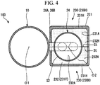
FIG. 4 is a cross-sectional view showing the configuration of the compressor system according to the second embodiment of the present invention. -
FIG. 5 is a longitudinal sectional view showing a configuration of a compressor system according to a third embodiment of the present invention. -
FIG. 6 is a cross-sectional view showing the configuration of the compressor system according to the third embodiment of the present invention. -
FIG. 7 is a longitudinal sectional view showing a modification example of a compressor system according to the respective embodiments of the present invention. - A first embodiment according to the present invention will be described with reference to
FIGS. 1 and2 . As shown inFIG. 1 , acompressor system 100 according to the present embodiment includes anaccumulator 24,suction pipes first suction pipe 26A andsecond suction pipe 26B), acompressor 10, and aninsulation container 30. Thecompressor 10 according to the present embodiment is a two-cylinder type rotary compressor. Thecompressor 10 includes amotor 18 driven by an external power source, acompression mechanism unit 10A driven by themotor 18 so as to compress a refrigerant, and ahousing 11 for covering themotor 18 and thecompression mechanism unit 10A. - The
compression mechanism unit 10A includes acrankshaft 16 rotated by themotor 18,piston rotors first piston rotor 13A andsecond piston rotor 13B) eccentrically rotated in accordance with rotation of thecrankshaft 16, andcylinders first cylinder 12A andsecond cylinder 12B) which internally have compression chambers for respectively accommodating thepiston rotors - In the
compression mechanism unit 10A, thefirst cylinder 12A and thesecond cylinder 12B which have a disk shape are disposed in two upper and lower stages inside thehousing 11 having a cylindrical shape. Thehousing 11 surrounds thefirst cylinder 12A and thesecond cylinder 12B so as to form a discharge space V to which a compressed refrigerant is discharged. The cylindricalfirst piston rotor 13A and the cylindricalsecond piston rotor 13B which have a smaller outer shape than an inner side of an inner wall surface thereof are respectively arranged inside thefirst cylinder 12A and thesecond cylinder 12B. Thefirst piston rotor 13A and thesecond piston rotor 13B are respectively inserted into and fixed toeccentric shaft portions - The
first piston rotor 13A of the upper stage cylinder and thesecond piston rotor 13 B of the lower stage cylinder have phases which are different from each other as much as 180°. A disk-shapedpartition plate 15 is disposed between thefirst cylinder 12A and thesecond cylinder 12B on the upper and lower stages. A space R inside thefirst cylinder 12A on the upper stage side and a space R inside thesecond cylinder 12B on the lower stage side is not allowed to communicate with each other by thepartition plate 15, and are partitioned into a compression chamber R1 and a compression chamber R2. - The
crankshaft 16 is supported so as to be rotatable around an axis O by anupper bearing portion 17A fixed to thefirst cylinder 12A and alower bearing portion 17B fixed to thesecond cylinder 12B. Thecrankshaft 16 has theeccentric shaft portions crankshaft 16. Theeccentric shaft portions crankshaft 16. In this manner, following pivoting movement thereof, thefirst piston rotor 13A and thesecond piston rotor 13B on the upper and lower stages are respectively and eccentrically rotated inside thefirst cylinder 12A and thesecond cylinder 12B. - The
crankshaft 16 protrudes upward (that is, a direction in which themotor 18 is located when viewed from thecompression mechanism unit 10A) from theupper bearing portion 17A. Arotor 19A of themotor 18 for rotationally driving thecrankshaft 16 is integrally disposed in a portion of thecrankshaft 16 which protrudes upward from theupper bearing portion 17A. Astator 19B is disposed by being fixed to an inner peripheral surface of thehousing 11 so as to face an outer peripheral portion of therotor 19A. - In the
compressor 10, theaccumulator 24 for separating the refrigerant into gas and liquid before the refrigerant is supplied to thecompressor 10 is fixed to thehousing 11 via astay 25. Theaccumulator 24 stores an uncompressed refrigerant. Afirst suction pipe 26A and asecond suction pipe 26B for suctioning the refrigerant stored in theaccumulator 24 into thecompressor 10 are disposed between theaccumulator 24 and thecompressor 10. One end of thefirst suction pipe 26A and thesecond suction pipe 26B is connected to a lower portion of theaccumulator 24. The other end of thefirst suction pipe 26A and thesecond suction pipe 26B passes throughopenings first opening 22A andsecond opening 22B) formed in thehousing 11, and is connected to suctionports first suction port 23A andsecond suction port 23B) respectively formed in thefirst cylinder 12A and thesecond cylinder 12B. Although details will be described later, central axes of thefirst suction pipe 26A and thesecond suction pipe 26B extend along mutually the same virtual plane. Specifically, thefirst suction pipe 26A and thesecond suction pipe 26B extend on the virtual plane including the first axis O1 of thecompressor 10 and a second axis O2 of theaccumulator 24. - The
compressor 10 fetches the refrigerant into theaccumulator 24 from asuction port 24a of theaccumulator 24. Specifically, inside theaccumulator 24, thecompressor 10 separates the refrigerant into a liquid-phase component and a gas-phase component. The separated gas-phase component is supplied from thefirst suction pipe 26A and thesecond suction pipe 26B via thefirst suction port 23A and thesecond suction port 23B to the compression chambers R1 and R2 serving as an internal space of thefirst cylinder 12A and thesecond cylinder 12B. - The
first piston rotor 13A and thesecond piston rotor 13B are eccentrically rotated. In this manner, each volume of the compression chambers R1 and R2 gradually decreases, and the refrigerant is compressed. The refrigerant passes through surroundings of themotor 18, and is then discharged to apipe 27 configuring a refrigeration cycle by way of a discharge port disposed in an upper portion. - In this way, the refrigerant (gas-phase component) compressed to have a high temperature and a high pressure circulates in the
compressor 10. In this manner, thecompressor 10 has a higher temperature than theaccumulator 24. Here, thecompressor 10 and theaccumulator 24 are close to each other. Accordingly, heat may be exchanged between thecompressor 10 and theaccumulator 24. Specifically, there is a possibility that the heat may be transferred from thecompressor 10 having the high temperature to theaccumulator 24 having the low temperature. In this case, the uncompressed refrigerant stored inside theaccumulator 24 is heated, thereby causing a possibility that the efficiency of thecompressor 10 may be reduced. - Therefore, the
compressor system 100 according to the present embodiment includes aninsulation container 30 for covering at least one entity of theaccumulator 24 and thecompressor 10 from an outside. According to the present embodiment, theinsulation container 30 covers both theaccumulator 24 and thecompressor 10. Theinsulation container 30 has a containermain body 31, aninsulation member 32, and abase plate 35. - The container
main body 31 has a rectangular parallelepiped shape for covering both theaccumulator 24 and thecompressor 10 from the outside. The containermain body 31 is located on thebase plate 35 fixed to a floor surface. A space inside the containermain body 31 is set to be aninternal space 31V. That is, theinternal space 31V is a space between an inner surface (containerinner surface 31A) of the containermain body 31 and an outer surface (apparatus outer surface S1) of theaccumulator 24, thefirst suction pipe 26A, thesecond suction pipe 26B, and thecompressor 10. The apparatus outer surface S1 described herein indicates the whole surface exposed outward in theaccumulator 24, thefirst suction pipe 26A, thesecond suction pipe 26B, and thecompressor 10. Theinsulation container 30 has through-holes H1 and H2 into which thepipe 27 and thesuction port 24a are inserted. Inside theinsulation container 30, thecompressor 10 is fixed to thebase plate 35 via a fixingmember 30F. - The
internal space 31V is buried without any gap by theinsulation member 32. Theinsulation member 32 is formed of a porous material, for example, such as a urethane resin and a styrene foam resin, which can hold a fixed shape and which has higher insulation properties than a metal material. A "fixed shape can be held" described herein indicates that a shape can be stably held against an external force even if the external force is applied thereto, unlike a material which is easily deformed as in glass wool or rock wool. - As shown in
FIG. 2 , according to the present embodiment, an inner surface (insulation memberinner surface 32A) of theinsulation member 32 has a shape extending along the apparatus outer surface S1. Furthermore, the insulation memberinner surface 32A and the apparatus outer surface S1 are in contact with each other without any gap. Theinsulation member 32 spreads so as to partition thecompressor 10 and theaccumulator 24 from each other. - The
insulation container 30 is separated into two members on a contact surface St serving as a boundary. More specifically, theinsulation container 30 has a pair of insulationcontainer half bodies 30H coming into contact with each other via the contact surface St. Each of the insulationcontainer half bodies 30H has a container main bodyseparable body 31H and an insulation memberseparable body 32H (separable body). The insulation memberseparable body 32H is fixed to an inner surface (containerinner surface 31A) of the container main bodyseparable body 31H so as not to be detachable therefrom. - The contact surface St is a plane including an extending direction of the
first suction pipe 26A and thesecond suction pipe 26B. As described above, the contact surface St is a plane including the first axis O1 of thecompressor 10 and the second axis O2 of theaccumulator 24. - Next, an operation of the
compressor system 100 according to the present embodiment will be described. If thecompressor system 100 is operated, thecompressor 10 emits the heat due to the compressed refrigerant as described above. Here, theaccumulator 24 is located close to thecompressor 10. Accordingly, there is a possibility that the heat generated by thecompressor 10 may be transferred to theaccumulator 24. However, according to the present embodiment, thecompressor 10 and theaccumulator 24 are thermally insulated by theinsulation member 32. Therefore, theinsulation member 32 reduces the heat exchange between thecompressor 10 and theaccumulator 24 and overheating loss caused by the heat exchange. As a result, the efficiency of thecompressor 10 can be prevented from being reduced. Furthermore, when thecompressor system 100 is operated, driving sound (radiation sound) is generated due to the drivenmotor 18. However, the porous material as described above is used as theinsulation member 32. Therefore, the driving sound can be attenuated in theinsulation member 32 without causing the driving sound to reach the outside. - Moreover, according to the above-described configuration, the
insulation member 32 is configured to include the pair of insulation memberseparable bodies 32H. Therefore, for example, when maintenance work is carried out for thecompressor 10 and theaccumulator 24, a user can easily reach thecompressor 10 and theaccumulator 24 by separating the insulation memberseparable bodies 32H on the contact surface St. Furthermore, after the maintenance work is completely carried out, the insulation memberseparable bodies 32H are brought into contact with each other via the contact surface St. In this manner, thecompressor 10 and theaccumulator 24 can easily return to a state of being covered with theinsulation member 32. In this way, according to the above-described configuration, the maintenance work can be easily and safely carried out for thecompressor system 100 while the insulation properties are ensured. - In addition, according to the above-described configuration, the insulation member
inner surface 32A is in contact with the outer surface (apparatus outer surface S1) of theaccumulator 24 and thecompressor 10 without any gap. Therefore, the heat generated by thecompressor 10 can be more efficiently absorbed by theinsulation member 32, and the heat exchange between theaccumulator 24 and thecompressor 10 can be further reduced. - In addition, according to the above-described configuration, the inner surface (insulation member
inner surface 32A) of theinsulation member 32 has a shape extending along the outer surface (apparatus outer surface S1) of theaccumulator 24 and thecompressor 10. Therefore, when theinsulation member 32 is attached to theaccumulator 24 and thecompressor 10, theinsulation member 32 can be easily positioned by guiding the insulation memberinner surface 32A. - Furthermore, according to the above-described configuration, the
insulation member 32 is formed of a material which can hold a fixed shape. Accordingly, even in a case where theinsulation member 32 is detached from theaccumulator 24 and thecompressor 10, theinsulation member 32 is in a state of holding the fixed shape. Therefore, compared to a case where theinsulation member 32 is formed of an amorphous material such as glass wool and rock wool, workability can be improved when theinsulation member 32 is attached again to theaccumulator 24 and thecompressor 10. - In addition, according to the above-described configuration, the contact surface St of the insulation member
separable body 32H (insulationcontainer half body 30H) is a plane including the extending direction of thefirst suction pipe 26A and thesecond suction pipe 26B. Accordingly, the insulationcontainer half body 30H can be smoothly detached or attached without being interfered with thefirst suction pipe 26A and thesecond suction pipe 26B. - Hitherto, the first embodiment according to the present invention has been described. Various modifications and improvements can be made to the above-described configurations without departing from the gist of the present invention. For example, in the above-described embodiment, an example has been described in which the container
main body 31 is formed in the rectangular parallelepiped shape. However, a shape of the containermain body 31 is not limited to the above-described example. As another example, the containermain body 31 may have an outer shell shape extending along the apparatus outer surface S1. According to this configuration, a dimensional size of thecompressor system 100 can be further minimized. - Next, a second embodiment according to the present invention will be described with reference to
FIGS. 3 and4 . The same reference numerals will be given to configurations which are the same as those according to the first embodiment, and detailed description thereof will be omitted. According to the present embodiment, aninsulation container 230 covers only theaccumulator 24 from the outside. Theinsulation container 230 has a containermain body 231 and aninsulation member 232. - The container
main body 231 has a rectangular parallelepiped shape for covering theaccumulator 24 from the outside. A space inside the containermain body 231 is set to be aninternal space 231V. That is, theinternal space 231V spreads between an inner surface (containerinner surface 231A) of the containermain body 231 and an outer surface (apparatus outer surface S2) of theaccumulator 24. The apparatus outer surface S2 described herein indicates the entire surface exposed outward in only theaccumulator 24. Theinsulation container 230 has a through-hole H3 into which thesuction port 24a is inserted. - The
internal space 231V is buried without any gap by theinsulation member 232. Theinsulation member 232 is formed of a porous material, for example, such as a urethane resin and a styrene foam resin, which can hold a fixed shape and which has higher insulation properties than a metal material. - According to the present embodiment, an inner surface (insulation member
inner surface 232A) of theinsulation member 232 has a shape extending along the apparatus outer surface S2. Furthermore, the insulation memberinner surface 232A and the apparatus outer surface S2 are in contact with each other without any gap. - The
insulation container 230 is separated into two members on the contact surface St serving as a boundary. More specifically, theinsulation container 230 has a pair of insulationcontainer half bodies 230H coming into contact with each other via the contact surface St. Each of the insulationcontainer half bodies 230H has a container main bodyseparable body 231H and an insulation memberseparable body 232H (separable body). The insulation memberseparable body 232H is fixed to an inner surface (containerinner surface 231A) of the container main bodyseparable body 231H so as not to be detachable therefrom. The contact surface St is a plane including the extending direction of thefirst suction pipe 26A and thesecond suction pipe 26B and the second axis O2 of theaccumulator 24. - According to the above-described configuration, the
accumulator 24 is covered with the insulation container 230 (insulation member 232). In this manner, propagation of the heat generated by thecompressor 10 to theaccumulator 24 can be reduced. Furthermore, theinsulation member 232 covers only theaccumulator 24. Accordingly, compared to a case where both theaccumulator 24 and thecompressor 10 are covered with theinsulation member 232, the dimensional size of the apparatus can be minimized. - Subsequently, a third embodiment according to the present invention will be described with reference to
FIGS. 5 and6 . The same reference numerals will be given to configurations which are the same as those according to the above-described embodiments, and detailed description thereof will be omitted. According to the present embodiment, aninsulation container 330 covers only thecompressor 10 from the outside. Theinsulation container 330 has a containermain body 331 and aninsulation member 332. - The container
main body 331 has a rectangular parallelepiped shape for covering thecompressor 10 from the outside. A space inside the containermain body 331 is set to be aninternal space 331V. That is, theinternal space 331V spreads between an inner surface (containerinner surface 331A) of the containermain body 331 and an outer surface (apparatus outer surface S3) of thecompressor 10. The apparatus outer surface S3 described herein indicates the entire surface exposed outward in only thecompressor 10. Theinsulation container 330 has a through-hole H4 into which thepipe 27 is inserted. - The
internal space 331V is filled with theinsulation member 332 without any gap. Theinsulation member 332 is formed of a porous material, for example, such as a urethane resin and a styrene foam resin, which can hold a fixed shape and which has higher insulation properties than a metal material. - According to the present embodiment, an inner surface (insulation member
inner surface 332A) of theinsulation member 332 has a shape extending along the apparatus outer surface S3. Furthermore, the insulation memberinner surface 332A and the apparatus outer surface S3 are in contact with each other without any gap therebetween. - The
insulation container 330 is separated into two members on the contact surface St serving as a boundary. More specifically, theinsulation container 330 has a pair of insulationcontainer half bodies 330H coming into contact with each other via the contact surface St. Each of the insulationcontainer half bodies 330H has a container main bodyseparable body 331H and an insulation memberseparable body 332H (separable body). The insulation memberseparable body 332H is fixed to an inner surface (containerinner surface 331A) of the container main bodyseparable body 331H so as not to be detachable therefrom. The contact surface St is a plane including the extending direction of thefirst suction pipe 26A and thesecond suction pipe 26B and the first axis O1 of thecompressor 10. - According to the above-described configuration, the
compressor 10 is covered with the insulation container 330 (insulation member 332). In this manner, propagation of the heat generated by thecompressor 10 to theaccumulator 24 can be reduced. Furthermore, theinsulation member 332 covers only thecompressor 10. Accordingly, compared to a case where both theaccumulator 24 and thecompressor 10 are covered with theinsulation member 332, the dimensional size of the apparatus can be minimized. - While preferred embodiments of the invention have been described and shown above, it should be understood that these are exemplary examples of the invention and are not to be considered as limiting. Additions, omissions, substitutions, and other modifications can be made without departing from the spirit or scope of the present invention. Accordingly, the invention is not to be considered as being limited by the foregoing description, and is only limited by the scope of the appended claims.
- For example, as a modification example common to the respective embodiments, it is also possible to adopt a configuration shown in
FIG. 7 . In the shown example, a gap G is formed between the insulation memberinner surface 32A and the apparatus outer surface S1. According to this configuration, since the gap G is formed therebetween, even in a case where an error or a tolerance occurs in the shape of the apparatus outer surface S1, the error or the tolerance is allowable. That is, the versatility of theinsulation container 30 can be improved. - According to the present invention, maintenance work can be easily and safely carried out while insulation properties are ensured.
- According to the present invention, maintenance work can be easily and safely carried out while insulation properties are ensured.
-
- 100: compressor system
- 10: compressor
- 10A: compression mechanism unit
- 11: housing
- 12A: first cylinder (cylinder)
- 12B: second cylinder (cylinder)
- R1, R2: compression chamber
- 13A: first piston rotor (piston rotor)
- 13B: second piston rotor (piston rotor)
- 14A, 14B: eccentric shaft portion
- 16: crankshaft
- 17A: upper bearing portion
- 17B: lower bearing portion
- 18: motor
- 19A: rotor
- 19B: stator
- 22A: first opening (opening)
- 22B: second opening (opening)
- 23A: first suction port (suction port)
- 23B: second suction port (suction port)
- 24: accumulator
- 24a: suction port
- 25: stay
- 26A: first suction pipe (suction pipe)
- 26B: second suction pipe (suction pipe)
- 27: pipe
- 30, 230, 330: insulation container
- 30F: fixing member
- 30H, 230H, 330H: insulation container half body
- 31, 231, 331: container main body
- 31A, 231A, 331A: container inner surface
- 31H, 231H, 331H: container main body separable body
- 31V, 231V, 331V: internal space
- 32, 232, 332: insulation member
- 32A, 232A, 332A: insulation member inner surface
- 32H, 232H, 332H: insulation member separable body
- 35: base plate
- O1: first axis
- O2: second axis
- S1, S2, S3: apparatus outer surface
- St: contact surface
- V: discharge space
Claims (8)
- A compressor system (100) comprising:an accumulator (24) that is configured to separate a refrigerant into a liquid-phase component and a gas-phase component;a suction pipe (26A, 26B), one end of which is connected to the accumulator (24) so as to circulate the gas-phase component therethrough;a compressor (10) that is connected to the other end of the suction pipe so as to compress the gas-phase component; andan insulation member (32, 232, 332) that covers an entity of at least one of the accumulator (24) and the compressor (10) from an outside,wherein the insulation member has at least a pair of separable bodies (32H) configured to come into contact with each other via a contact surface (St).
- The compressor system (100) according to Claim 1,
wherein an inner surface (32A) of the insulation member has a shape extending along at least one outer surface of the accumulator (24) and the compressor (10). - The compressor system (100) according to Claim 1 or 2,
wherein an inner surface (32A) of the insulation member is in contact with at least one outer surface of the accumulator (24) and the compressor (10). - The compressor system (100) according to any one of Claims 1 to 3,
wherein the insulation member (32) covers both the accumulator (24) and the compressor (10). - The compressor system (100) according to any one of Claims 1 to 3,
wherein the insulation member (32) covers only the accumulator (24). - The compressor system (100) according to any one of Claims 1 to 3,
wherein the insulation member (32) covers only the compressor (10). - The compressor system (100) according to any one of Claims 1 to 6,
wherein the insulation member (32) is formed of a material capable of holding a fixed shape. - The compressor system (100) according to any one of Claims 1 to 7,
wherein the contact surface (St) is a plane including an extending direction of the suction pipe (26A, 26B).
Applications Claiming Priority (1)
| Application Number | Priority Date | Filing Date | Title |
|---|---|---|---|
| JP2018074091A JP2019183721A (en) | 2018-04-06 | 2018-04-06 | Compressor system |
Publications (2)
| Publication Number | Publication Date |
|---|---|
| EP3550224A1 true EP3550224A1 (en) | 2019-10-09 |
| EP3550224B1 EP3550224B1 (en) | 2021-12-08 |
Family
ID=66092243
Family Applications (1)
| Application Number | Title | Priority Date | Filing Date |
|---|---|---|---|
| EP19167395.3A Active EP3550224B1 (en) | 2018-04-06 | 2019-04-04 | Compressor system |
Country Status (2)
| Country | Link |
|---|---|
| EP (1) | EP3550224B1 (en) |
| JP (1) | JP2019183721A (en) |
Cited By (3)
| Publication number | Priority date | Publication date | Assignee | Title |
|---|---|---|---|---|
| CN115200265A (en) * | 2022-07-27 | 2022-10-18 | 格力电器(芜湖)有限公司 | Compressors and Air Conditioning Units |
| CN117425780A (en) * | 2021-06-07 | 2024-01-19 | 富士通将军股份有限公司 | Hermetic compressor |
| US12565892B2 (en) | 2021-07-06 | 2026-03-03 | Fujitsu General Limited | Hermetic type compressor |
Families Citing this family (1)
| Publication number | Priority date | Publication date | Assignee | Title |
|---|---|---|---|---|
| JP7306436B2 (en) * | 2021-09-21 | 2023-07-11 | 株式会社富士通ゼネラル | hermetic compressor |
Citations (9)
| Publication number | Priority date | Publication date | Assignee | Title |
|---|---|---|---|---|
| JPH01159476A (en) * | 1987-09-18 | 1989-06-22 | Mitsubishi Electric Corp | Sound arrestor for compressor |
| JP2004360622A (en) * | 2003-06-06 | 2004-12-24 | Matsushita Electric Ind Co Ltd | Accumulator for multi-cylinder compressor |
| EP1596067A1 (en) * | 2004-05-14 | 2005-11-16 | COPELAND CORPORATION (a Delaware corp.) | Compressor sound attenuation |
| JP2008133758A (en) * | 2006-11-28 | 2008-06-12 | Daikin Ind Ltd | Refrigeration equipment |
| JP2008175413A (en) | 2007-01-16 | 2008-07-31 | Daikin Ind Ltd | Refrigeration equipment |
| WO2013046591A1 (en) * | 2011-09-26 | 2013-04-04 | ダイキン工業株式会社 | Outdoor unit |
| JP2015160581A (en) * | 2014-02-28 | 2015-09-07 | 株式会社デンソー | Compressor and vehicle air conditioner |
| EP2942526A1 (en) * | 2013-03-12 | 2015-11-11 | Mitsubishi Heavy Industries, Ltd. | Rotary compressor |
| EP3290697A1 (en) * | 2015-04-28 | 2018-03-07 | Daikin Industries, Ltd. | Soundproof cover of compressor for air conditioner |
-
2018
- 2018-04-06 JP JP2018074091A patent/JP2019183721A/en active Pending
-
2019
- 2019-04-04 EP EP19167395.3A patent/EP3550224B1/en active Active
Patent Citations (9)
| Publication number | Priority date | Publication date | Assignee | Title |
|---|---|---|---|---|
| JPH01159476A (en) * | 1987-09-18 | 1989-06-22 | Mitsubishi Electric Corp | Sound arrestor for compressor |
| JP2004360622A (en) * | 2003-06-06 | 2004-12-24 | Matsushita Electric Ind Co Ltd | Accumulator for multi-cylinder compressor |
| EP1596067A1 (en) * | 2004-05-14 | 2005-11-16 | COPELAND CORPORATION (a Delaware corp.) | Compressor sound attenuation |
| JP2008133758A (en) * | 2006-11-28 | 2008-06-12 | Daikin Ind Ltd | Refrigeration equipment |
| JP2008175413A (en) | 2007-01-16 | 2008-07-31 | Daikin Ind Ltd | Refrigeration equipment |
| WO2013046591A1 (en) * | 2011-09-26 | 2013-04-04 | ダイキン工業株式会社 | Outdoor unit |
| EP2942526A1 (en) * | 2013-03-12 | 2015-11-11 | Mitsubishi Heavy Industries, Ltd. | Rotary compressor |
| JP2015160581A (en) * | 2014-02-28 | 2015-09-07 | 株式会社デンソー | Compressor and vehicle air conditioner |
| EP3290697A1 (en) * | 2015-04-28 | 2018-03-07 | Daikin Industries, Ltd. | Soundproof cover of compressor for air conditioner |
Cited By (3)
| Publication number | Priority date | Publication date | Assignee | Title |
|---|---|---|---|---|
| CN117425780A (en) * | 2021-06-07 | 2024-01-19 | 富士通将军股份有限公司 | Hermetic compressor |
| US12565892B2 (en) | 2021-07-06 | 2026-03-03 | Fujitsu General Limited | Hermetic type compressor |
| CN115200265A (en) * | 2022-07-27 | 2022-10-18 | 格力电器(芜湖)有限公司 | Compressors and Air Conditioning Units |
Also Published As
| Publication number | Publication date |
|---|---|
| EP3550224B1 (en) | 2021-12-08 |
| JP2019183721A (en) | 2019-10-24 |
Similar Documents
| Publication | Publication Date | Title |
|---|---|---|
| EP3550224B1 (en) | Compressor system | |
| US10180271B2 (en) | Multiple cylinder rotary compressor and refrigeration cycle apparatus | |
| EP3376035B1 (en) | Rotary compressor | |
| KR20160017993A (en) | Compressor | |
| EP2889486A1 (en) | Gas compressor | |
| EP2905470B1 (en) | Rotary compressor | |
| CN104428536B (en) | Rotary compressor | |
| US20170321684A1 (en) | Linear compressor | |
| EP3951181B1 (en) | Rotary compressor | |
| KR20200140967A (en) | Motor operated compressor | |
| JPWO2017103988A1 (en) | Compressor for binary refrigeration equipment and binary refrigeration equipment | |
| EP3550147B1 (en) | Compressor system | |
| JP7012843B2 (en) | Sealed compressor and manufacturing method of sealed compressor | |
| KR102392655B1 (en) | Compressor having seperated oil retrun flow path and refrigerant flow path | |
| KR101573938B1 (en) | compressor | |
| JPWO2016017281A1 (en) | Rotary compressor and refrigeration cycle apparatus | |
| EP2857687A1 (en) | Gas compressor | |
| EP3550146B1 (en) | Compressor system | |
| WO2015190551A1 (en) | Compressor | |
| EP3690247A1 (en) | Scroll compressor | |
| KR20110015852A (en) | compressor | |
| KR20160082205A (en) | Compressor | |
| JP2023180461A (en) | rotary compressor | |
| EP4424996B1 (en) | Rotary compressor | |
| KR101563004B1 (en) | compressor |
Legal Events
| Date | Code | Title | Description |
|---|---|---|---|
| PUAI | Public reference made under article 153(3) epc to a published international application that has entered the european phase |
Free format text: ORIGINAL CODE: 0009012 |
|
| STAA | Information on the status of an ep patent application or granted ep patent |
Free format text: STATUS: THE APPLICATION HAS BEEN PUBLISHED |
|
| AK | Designated contracting states |
Kind code of ref document: A1 Designated state(s): AL AT BE BG CH CY CZ DE DK EE ES FI FR GB GR HR HU IE IS IT LI LT LU LV MC MK MT NL NO PL PT RO RS SE SI SK SM TR |
|
| AX | Request for extension of the european patent |
Extension state: BA ME |
|
| STAA | Information on the status of an ep patent application or granted ep patent |
Free format text: STATUS: REQUEST FOR EXAMINATION WAS MADE |
|
| 17P | Request for examination filed |
Effective date: 20200409 |
|
| RBV | Designated contracting states (corrected) |
Designated state(s): AL AT BE BG CH CY CZ DE DK EE ES FI FR GB GR HR HU IE IS IT LI LT LU LV MC MK MT NL NO PL PT RO RS SE SI SK SM TR |
|
| STAA | Information on the status of an ep patent application or granted ep patent |
Free format text: STATUS: EXAMINATION IS IN PROGRESS |
|
| 17Q | First examination report despatched |
Effective date: 20200706 |
|
| GRAP | Despatch of communication of intention to grant a patent |
Free format text: ORIGINAL CODE: EPIDOSNIGR1 |
|
| STAA | Information on the status of an ep patent application or granted ep patent |
Free format text: STATUS: GRANT OF PATENT IS INTENDED |
|
| INTG | Intention to grant announced |
Effective date: 20210716 |
|
| GRAS | Grant fee paid |
Free format text: ORIGINAL CODE: EPIDOSNIGR3 |
|
| GRAA | (expected) grant |
Free format text: ORIGINAL CODE: 0009210 |
|
| STAA | Information on the status of an ep patent application or granted ep patent |
Free format text: STATUS: THE PATENT HAS BEEN GRANTED |
|
| AK | Designated contracting states |
Kind code of ref document: B1 Designated state(s): AL AT BE BG CH CY CZ DE DK EE ES FI FR GB GR HR HU IE IS IT LI LT LU LV MC MK MT NL NO PL PT RO RS SE SI SK SM TR |
|
| REG | Reference to a national code |
Ref country code: GB Ref legal event code: FG4D |
|
| REG | Reference to a national code |
Ref country code: AT Ref legal event code: REF Ref document number: 1454071 Country of ref document: AT Kind code of ref document: T Effective date: 20211215 Ref country code: CH Ref legal event code: EP |
|
| REG | Reference to a national code |
Ref country code: DE Ref legal event code: R096 Ref document number: 602019009810 Country of ref document: DE |
|
| REG | Reference to a national code |
Ref country code: IE Ref legal event code: FG4D |
|
| REG | Reference to a national code |
Ref country code: LT Ref legal event code: MG9D |
|
| REG | Reference to a national code |
Ref country code: NL Ref legal event code: MP Effective date: 20211208 |
|
| PG25 | Lapsed in a contracting state [announced via postgrant information from national office to epo] |
Ref country code: RS Free format text: LAPSE BECAUSE OF FAILURE TO SUBMIT A TRANSLATION OF THE DESCRIPTION OR TO PAY THE FEE WITHIN THE PRESCRIBED TIME-LIMIT Effective date: 20211208 Ref country code: LT Free format text: LAPSE BECAUSE OF FAILURE TO SUBMIT A TRANSLATION OF THE DESCRIPTION OR TO PAY THE FEE WITHIN THE PRESCRIBED TIME-LIMIT Effective date: 20211208 Ref country code: FI Free format text: LAPSE BECAUSE OF FAILURE TO SUBMIT A TRANSLATION OF THE DESCRIPTION OR TO PAY THE FEE WITHIN THE PRESCRIBED TIME-LIMIT Effective date: 20211208 Ref country code: BG Free format text: LAPSE BECAUSE OF FAILURE TO SUBMIT A TRANSLATION OF THE DESCRIPTION OR TO PAY THE FEE WITHIN THE PRESCRIBED TIME-LIMIT Effective date: 20220308 |
|
| REG | Reference to a national code |
Ref country code: AT Ref legal event code: MK05 Ref document number: 1454071 Country of ref document: AT Kind code of ref document: T Effective date: 20211208 |
|
| PG25 | Lapsed in a contracting state [announced via postgrant information from national office to epo] |
Ref country code: SE Free format text: LAPSE BECAUSE OF FAILURE TO SUBMIT A TRANSLATION OF THE DESCRIPTION OR TO PAY THE FEE WITHIN THE PRESCRIBED TIME-LIMIT Effective date: 20211208 Ref country code: NO Free format text: LAPSE BECAUSE OF FAILURE TO SUBMIT A TRANSLATION OF THE DESCRIPTION OR TO PAY THE FEE WITHIN THE PRESCRIBED TIME-LIMIT Effective date: 20220308 Ref country code: LV Free format text: LAPSE BECAUSE OF FAILURE TO SUBMIT A TRANSLATION OF THE DESCRIPTION OR TO PAY THE FEE WITHIN THE PRESCRIBED TIME-LIMIT Effective date: 20211208 Ref country code: HR Free format text: LAPSE BECAUSE OF FAILURE TO SUBMIT A TRANSLATION OF THE DESCRIPTION OR TO PAY THE FEE WITHIN THE PRESCRIBED TIME-LIMIT Effective date: 20211208 Ref country code: GR Free format text: LAPSE BECAUSE OF FAILURE TO SUBMIT A TRANSLATION OF THE DESCRIPTION OR TO PAY THE FEE WITHIN THE PRESCRIBED TIME-LIMIT Effective date: 20220309 Ref country code: ES Free format text: LAPSE BECAUSE OF FAILURE TO SUBMIT A TRANSLATION OF THE DESCRIPTION OR TO PAY THE FEE WITHIN THE PRESCRIBED TIME-LIMIT Effective date: 20211208 |
|
| PG25 | Lapsed in a contracting state [announced via postgrant information from national office to epo] |
Ref country code: NL Free format text: LAPSE BECAUSE OF FAILURE TO SUBMIT A TRANSLATION OF THE DESCRIPTION OR TO PAY THE FEE WITHIN THE PRESCRIBED TIME-LIMIT Effective date: 20211208 |
|
| PG25 | Lapsed in a contracting state [announced via postgrant information from national office to epo] |
Ref country code: SM Free format text: LAPSE BECAUSE OF FAILURE TO SUBMIT A TRANSLATION OF THE DESCRIPTION OR TO PAY THE FEE WITHIN THE PRESCRIBED TIME-LIMIT Effective date: 20211208 Ref country code: SK Free format text: LAPSE BECAUSE OF FAILURE TO SUBMIT A TRANSLATION OF THE DESCRIPTION OR TO PAY THE FEE WITHIN THE PRESCRIBED TIME-LIMIT Effective date: 20211208 Ref country code: RO Free format text: LAPSE BECAUSE OF FAILURE TO SUBMIT A TRANSLATION OF THE DESCRIPTION OR TO PAY THE FEE WITHIN THE PRESCRIBED TIME-LIMIT Effective date: 20211208 Ref country code: PT Free format text: LAPSE BECAUSE OF FAILURE TO SUBMIT A TRANSLATION OF THE DESCRIPTION OR TO PAY THE FEE WITHIN THE PRESCRIBED TIME-LIMIT Effective date: 20220408 Ref country code: EE Free format text: LAPSE BECAUSE OF FAILURE TO SUBMIT A TRANSLATION OF THE DESCRIPTION OR TO PAY THE FEE WITHIN THE PRESCRIBED TIME-LIMIT Effective date: 20211208 Ref country code: CZ Free format text: LAPSE BECAUSE OF FAILURE TO SUBMIT A TRANSLATION OF THE DESCRIPTION OR TO PAY THE FEE WITHIN THE PRESCRIBED TIME-LIMIT Effective date: 20211208 |
|
| PG25 | Lapsed in a contracting state [announced via postgrant information from national office to epo] |
Ref country code: PL Free format text: LAPSE BECAUSE OF FAILURE TO SUBMIT A TRANSLATION OF THE DESCRIPTION OR TO PAY THE FEE WITHIN THE PRESCRIBED TIME-LIMIT Effective date: 20211208 Ref country code: AT Free format text: LAPSE BECAUSE OF FAILURE TO SUBMIT A TRANSLATION OF THE DESCRIPTION OR TO PAY THE FEE WITHIN THE PRESCRIBED TIME-LIMIT Effective date: 20211208 |
|
| REG | Reference to a national code |
Ref country code: DE Ref legal event code: R097 Ref document number: 602019009810 Country of ref document: DE |
|
| PG25 | Lapsed in a contracting state [announced via postgrant information from national office to epo] |
Ref country code: IS Free format text: LAPSE BECAUSE OF FAILURE TO SUBMIT A TRANSLATION OF THE DESCRIPTION OR TO PAY THE FEE WITHIN THE PRESCRIBED TIME-LIMIT Effective date: 20220408 |
|
| PLBE | No opposition filed within time limit |
Free format text: ORIGINAL CODE: 0009261 |
|
| STAA | Information on the status of an ep patent application or granted ep patent |
Free format text: STATUS: NO OPPOSITION FILED WITHIN TIME LIMIT |
|
| PG25 | Lapsed in a contracting state [announced via postgrant information from national office to epo] |
Ref country code: DK Free format text: LAPSE BECAUSE OF FAILURE TO SUBMIT A TRANSLATION OF THE DESCRIPTION OR TO PAY THE FEE WITHIN THE PRESCRIBED TIME-LIMIT Effective date: 20211208 Ref country code: AL Free format text: LAPSE BECAUSE OF FAILURE TO SUBMIT A TRANSLATION OF THE DESCRIPTION OR TO PAY THE FEE WITHIN THE PRESCRIBED TIME-LIMIT Effective date: 20211208 |
|
| 26N | No opposition filed |
Effective date: 20220909 |
|
| PG25 | Lapsed in a contracting state [announced via postgrant information from national office to epo] |
Ref country code: SI Free format text: LAPSE BECAUSE OF FAILURE TO SUBMIT A TRANSLATION OF THE DESCRIPTION OR TO PAY THE FEE WITHIN THE PRESCRIBED TIME-LIMIT Effective date: 20211208 |
|
| REG | Reference to a national code |
Ref country code: CH Ref legal event code: PL |
|
| REG | Reference to a national code |
Ref country code: BE Ref legal event code: MM Effective date: 20220430 |
|
| PG25 | Lapsed in a contracting state [announced via postgrant information from national office to epo] |
Ref country code: MC Free format text: LAPSE BECAUSE OF FAILURE TO SUBMIT A TRANSLATION OF THE DESCRIPTION OR TO PAY THE FEE WITHIN THE PRESCRIBED TIME-LIMIT Effective date: 20211208 Ref country code: LU Free format text: LAPSE BECAUSE OF NON-PAYMENT OF DUE FEES Effective date: 20220404 Ref country code: LI Free format text: LAPSE BECAUSE OF NON-PAYMENT OF DUE FEES Effective date: 20220430 Ref country code: CH Free format text: LAPSE BECAUSE OF NON-PAYMENT OF DUE FEES Effective date: 20220430 |
|
| PG25 | Lapsed in a contracting state [announced via postgrant information from national office to epo] |
Ref country code: BE Free format text: LAPSE BECAUSE OF NON-PAYMENT OF DUE FEES Effective date: 20220430 |
|
| REG | Reference to a national code |
Ref country code: DE Ref legal event code: R082 Ref document number: 602019009810 Country of ref document: DE Representative=s name: CBDL PATENTANWAELTE GBR, DE Ref country code: DE Ref legal event code: R082 Ref document number: 602019009810 Country of ref document: DE Representative=s name: CBDL PATENTANWAELTE EGBR, DE |
|
| PG25 | Lapsed in a contracting state [announced via postgrant information from national office to epo] |
Ref country code: IE Free format text: LAPSE BECAUSE OF NON-PAYMENT OF DUE FEES Effective date: 20220404 |
|
| PG25 | Lapsed in a contracting state [announced via postgrant information from national office to epo] |
Ref country code: IT Free format text: LAPSE BECAUSE OF FAILURE TO SUBMIT A TRANSLATION OF THE DESCRIPTION OR TO PAY THE FEE WITHIN THE PRESCRIBED TIME-LIMIT Effective date: 20211208 |
|
| PG25 | Lapsed in a contracting state [announced via postgrant information from national office to epo] |
Ref country code: HU Free format text: LAPSE BECAUSE OF FAILURE TO SUBMIT A TRANSLATION OF THE DESCRIPTION OR TO PAY THE FEE WITHIN THE PRESCRIBED TIME-LIMIT; INVALID AB INITIO Effective date: 20190404 |
|
| PG25 | Lapsed in a contracting state [announced via postgrant information from national office to epo] |
Ref country code: MK Free format text: LAPSE BECAUSE OF FAILURE TO SUBMIT A TRANSLATION OF THE DESCRIPTION OR TO PAY THE FEE WITHIN THE PRESCRIBED TIME-LIMIT Effective date: 20211208 Ref country code: CY Free format text: LAPSE BECAUSE OF FAILURE TO SUBMIT A TRANSLATION OF THE DESCRIPTION OR TO PAY THE FEE WITHIN THE PRESCRIBED TIME-LIMIT Effective date: 20211208 |
|
| PG25 | Lapsed in a contracting state [announced via postgrant information from national office to epo] |
Ref country code: MT Free format text: LAPSE BECAUSE OF FAILURE TO SUBMIT A TRANSLATION OF THE DESCRIPTION OR TO PAY THE FEE WITHIN THE PRESCRIBED TIME-LIMIT Effective date: 20211208 |
|
| PGFP | Annual fee paid to national office [announced via postgrant information from national office to epo] |
Ref country code: DE Payment date: 20250305 Year of fee payment: 7 |
|
| PG25 | Lapsed in a contracting state [announced via postgrant information from national office to epo] |
Ref country code: TR Free format text: LAPSE BECAUSE OF FAILURE TO SUBMIT A TRANSLATION OF THE DESCRIPTION OR TO PAY THE FEE WITHIN THE PRESCRIBED TIME-LIMIT Effective date: 20211208 |
|
| PGFP | Annual fee paid to national office [announced via postgrant information from national office to epo] |
Ref country code: GB Payment date: 20260313 Year of fee payment: 8 |
|
| PGFP | Annual fee paid to national office [announced via postgrant information from national office to epo] |
Ref country code: FR Payment date: 20260309 Year of fee payment: 8 |