EP3550176B1 - Energy absorbing device with fall indicator for lifelines - Google Patents
Energy absorbing device with fall indicator for lifelines Download PDFInfo
- Publication number
- EP3550176B1 EP3550176B1 EP18209587.7A EP18209587A EP3550176B1 EP 3550176 B1 EP3550176 B1 EP 3550176B1 EP 18209587 A EP18209587 A EP 18209587A EP 3550176 B1 EP3550176 B1 EP 3550176B1
- Authority
- EP
- European Patent Office
- Prior art keywords
- spirals
- spiral
- rolled
- winding shaft
- energy absorbing
- Prior art date
- Legal status (The legal status is an assumption and is not a legal conclusion. Google has not performed a legal analysis and makes no representation as to the accuracy of the status listed.)
- Active
Links
Images


Classifications
-
- F—MECHANICAL ENGINEERING; LIGHTING; HEATING; WEAPONS; BLASTING
- F16—ENGINEERING ELEMENTS AND UNITS; GENERAL MEASURES FOR PRODUCING AND MAINTAINING EFFECTIVE FUNCTIONING OF MACHINES OR INSTALLATIONS; THERMAL INSULATION IN GENERAL
- F16F—SPRINGS; SHOCK-ABSORBERS; MEANS FOR DAMPING VIBRATION
- F16F7/00—Vibration-dampers; Shock-absorbers
- F16F7/12—Vibration-dampers; Shock-absorbers using plastic deformation of members
- F16F7/128—Vibration-dampers; Shock-absorbers using plastic deformation of members characterised by the members, e.g. a flat strap, yielding through stretching, pulling apart
-
- A—HUMAN NECESSITIES
- A62—LIFE-SAVING; FIRE-FIGHTING
- A62B—DEVICES, APPARATUS OR METHODS FOR LIFE-SAVING
- A62B35/00—Safety belts or body harnesses; Similar equipment for limiting displacement of the human body, especially in case of sudden changes of motion
- A62B35/04—Safety belts or body harnesses; Similar equipment for limiting displacement of the human body, especially in case of sudden changes of motion incorporating energy absorbing means
-
- F—MECHANICAL ENGINEERING; LIGHTING; HEATING; WEAPONS; BLASTING
- F16—ENGINEERING ELEMENTS AND UNITS; GENERAL MEASURES FOR PRODUCING AND MAINTAINING EFFECTIVE FUNCTIONING OF MACHINES OR INSTALLATIONS; THERMAL INSULATION IN GENERAL
- F16F—SPRINGS; SHOCK-ABSORBERS; MEANS FOR DAMPING VIBRATION
- F16F7/00—Vibration-dampers; Shock-absorbers
- F16F7/003—One-shot shock absorbers
-
- F—MECHANICAL ENGINEERING; LIGHTING; HEATING; WEAPONS; BLASTING
- F16—ENGINEERING ELEMENTS AND UNITS; GENERAL MEASURES FOR PRODUCING AND MAINTAINING EFFECTIVE FUNCTIONING OF MACHINES OR INSTALLATIONS; THERMAL INSULATION IN GENERAL
- F16F—SPRINGS; SHOCK-ABSORBERS; MEANS FOR DAMPING VIBRATION
- F16F7/00—Vibration-dampers; Shock-absorbers
- F16F7/12—Vibration-dampers; Shock-absorbers using plastic deformation of members
- F16F7/123—Deformation involving a bending action, e.g. strap moving through multiple rollers, folding of members
-
- F—MECHANICAL ENGINEERING; LIGHTING; HEATING; WEAPONS; BLASTING
- F16—ENGINEERING ELEMENTS AND UNITS; GENERAL MEASURES FOR PRODUCING AND MAINTAINING EFFECTIVE FUNCTIONING OF MACHINES OR INSTALLATIONS; THERMAL INSULATION IN GENERAL
- F16F—SPRINGS; SHOCK-ABSORBERS; MEANS FOR DAMPING VIBRATION
- F16F1/00—Springs
- F16F1/02—Springs made of steel or other material having low internal friction; Wound, torsion, leaf, cup, ring or the like springs, the material of the spring not being relevant
- F16F1/025—Springs made of steel or other material having low internal friction; Wound, torsion, leaf, cup, ring or the like springs, the material of the spring not being relevant characterised by having a particular shape
- F16F1/027—Planar, e.g. in sheet form; leaf springs
-
- F—MECHANICAL ENGINEERING; LIGHTING; HEATING; WEAPONS; BLASTING
- F16—ENGINEERING ELEMENTS AND UNITS; GENERAL MEASURES FOR PRODUCING AND MAINTAINING EFFECTIVE FUNCTIONING OF MACHINES OR INSTALLATIONS; THERMAL INSULATION IN GENERAL
- F16F—SPRINGS; SHOCK-ABSORBERS; MEANS FOR DAMPING VIBRATION
- F16F3/00—Spring units consisting of several springs, e.g. for obtaining a desired spring characteristic
- F16F3/02—Spring units consisting of several springs, e.g. for obtaining a desired spring characteristic with springs made of steel or of other material having low internal friction
-
- F—MECHANICAL ENGINEERING; LIGHTING; HEATING; WEAPONS; BLASTING
- F16—ENGINEERING ELEMENTS AND UNITS; GENERAL MEASURES FOR PRODUCING AND MAINTAINING EFFECTIVE FUNCTIONING OF MACHINES OR INSTALLATIONS; THERMAL INSULATION IN GENERAL
- F16F—SPRINGS; SHOCK-ABSORBERS; MEANS FOR DAMPING VIBRATION
- F16F7/00—Vibration-dampers; Shock-absorbers
- F16F7/14—Vibration-dampers; Shock-absorbers of cable support type, i.e. frictionally-engaged loop-forming cables
Definitions
- Energy absorbing device with fall indicator for lifelines of the type comprising a winding shaft, a first rolled spiral, which defines two ends, one free first end, which is connected to a cable or a fixed element, and a second end, which is rolled on the winding shaft, characterized by comprising two identical second spirals, arranged parallel to each other and configuring a fork on the sides of the first spiral, said second spirals configure third free ends, arranged in the opposite direction to the free first end, wherein fourth ends of the second spirals are maintained rolled on the winding shaft; such that the two second spirals are rolled on the winding shaft in the opposite direction to that of the first spiral, being the first spiral twice as thick as each of the two second spirals.
- This invention belongs to the field of energy absorbing devices that increase the braking power of hanging people or materials attached.
- the invention is defined in the appended claims.
- the device has the advantage of a smaller size, being configured as a spring.
- This invention solves prior problems by providing a set of springs, arranged sandwich-like, which springs are connected to each other by a winding shafts, thus allowing the spring run to double, while maintaining the same braking power, or, what is the same, doubling the kinetic energy that the device is capable of absorbing.
- the size of the absorber is reduced, which makes it ideal to be combined with lifelines that have to stay as near as possible to the anchorage point.
- the total or partial unrolling of the device provides evidence to the fall indicator, that is, that the lifeline has undergone an anomalous effort with respect to its correct use.
- Energy absorbing device with fall indicator for lifelines of the type comprising a winding shaft, a first rolled spiral, which defines two ends, one free first end, which is connected to a cable or a fixed element, and a second end, which is rolled on the winding shaft, characterized by comprising two identical second spirals, arranged parallel to each other and configuring a fork on the sides of the first spiral, said second spirals configure third free ends, arranged in the opposite direction to the free first end, wherein fourth ends of the second spirals are maintained rolled on the winding shaft; such that the two second spirals are rolled on the winding shaft in the opposite direction to that of the first spiral, being the first spiral twice as thick as each of the two second spirals.
- Figure 1 shows a first spiral 1 with one first end 2, second spirals 3, 4 with third ends 5, 6 respectively, a lid 10, and a winding shaft 7.
- Figure 2 shows first spiral 1 having a first end 2 and a second end 8, second spirals 3, 4 having the third ends 5, 6 and one fourth end 9, lid 10 and winding shaft 7.
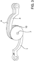
- Figure 3 shows spiral 1, second spirals 3, 4, lid 10 and winding shaft 7.
- first end 2 affixed to an anchoring device (not shown) and third ends 5, 6 to a lifeline.
- the anchoring device is designed to ensure the mechanical strength necessary to withstand the stress produced in an event of a fall, which will be transmitted to the host structure (not shown) of said anchoring device.
- the first end 2 is affixed to an anchoring device, which in turn is affixed to a host structure (for example, a wall), the first spiral 1 will be pushed downwards by the action of the hanging person and of the second spirals in the second end, the second end 8 will rotate, causing the unrolling of the first spiral, and the first spiral will stretch, having the first end 2 affixed to the anchoring device.
- a host structure for example, a wall
- the second spirals 3, 4 also unroll, since the fourth ends 9 rotate, and the second spirals 3, 4 stretch out as the hanging person pull them.
- the advantage is that the sandwich-like arrangement allows doubling the kinetic energy that the device is capable of absorbing, thus increasing the safety.
- eyelet-fork connections a plate with a hole on one side, two separate pierced plates on the other side
- eyeline terminals either horizontal or vertical.
- the two second spirals 3, 4 ( FIG. 3 ) are rolled on the winding shaft 7 in an opposite direction to that of first spiral 2, so that when it unrolls in an inverted direction to the direction of the stretching of the first spiral 1, the second spirals 3, 4 also contribute to increasing the absorption capacity of the device.
- spirals 1, 3,4 in one single piece ( FIG.2 ), for example by laser cutting, being already rolled up from the beginning.
- Each of the second spirals 3, 4 is half thick as the first spiral 1. This allows greater stability to the whole set, since second spirals 3, 4 being side by side the first spiral 1, unroll simultaneously.
- both second spirals 3, 4 having an aggregated thickness equal to that of first spiral 1, this allows for the absorber to deform in a constant manner.
- This invention describes a new energy absorbing device with fall indicator for lifelines.
- the examples herein mentioned do not limit the present invention, which may have different applications and/or adaptations, all of which are within the scope of the following claims.
Landscapes
- Engineering & Computer Science (AREA)
- General Engineering & Computer Science (AREA)
- Mechanical Engineering (AREA)
- Health & Medical Sciences (AREA)
- General Health & Medical Sciences (AREA)
- Business, Economics & Management (AREA)
- Emergency Management (AREA)
- Vibration Dampers (AREA)
- Hydraulic Turbines (AREA)
- Emergency Lowering Means (AREA)
Description
- Energy absorbing device with fall indicator for lifelines, of the type comprising a winding shaft, a first rolled spiral, which defines two ends, one free first end, which is connected to a cable or a fixed element, and a second end, which is rolled on the winding shaft, characterized by comprising two identical second spirals, arranged parallel to each other and configuring a fork on the sides of the first spiral, said second spirals configure third free ends, arranged in the opposite direction to the free first end, wherein fourth ends of the second spirals are maintained rolled on the winding shaft; such that the two second spirals are rolled on the winding shaft in the opposite direction to that of the first spiral, being the first spiral twice as thick as each of the two second spirals.
- Different energy absorbing devices are known in the state of the art.
- Thus, state of the art is
US Patent No. 4791243 "COMPACT DEVICE FOR LONG STROKE ENERGY ABSORPTION", dated 1987, in the name of ANCO ENGINEERS INC., which refers to a compact device for absorbing kinetic energy generated by, for example, broken electric power lines in electric power transmission towers. The device consists of a non-spring helix, or flat or not flat coils that are placed between an electric transmission tower and the conductor insulator. The device deforms by plastically unrolling in response to forces greater than a predetermined force. The device is a single-event device, designed to be replaced after one extraordinary dynamic event. The device can also be used in other structures or machinery requiring compact long-stroke energy absorption.GB2426563 - This invention belongs to the field of energy absorbing devices that increase the braking power of hanging people or materials attached. The invention is defined in the appended claims.
- A similar document to this invention is
US Patent US4791243 . Such invention is intended to avoid that hanging elements are stopped subsequently to a dynamic event, such as, for example, a fall. - The device has the advantage of a smaller size, being configured as a spring.
- On the other hand, its disadvantage is that in order to increase the absorption capacity, the size of the spring must be enlarged too, making it impossible to combine it with a lifeline.
- This invention solves prior problems by providing a set of springs, arranged sandwich-like, which springs are connected to each other by a winding shafts, thus allowing the spring run to double, while maintaining the same braking power, or, what is the same, doubling the kinetic energy that the device is capable of absorbing.
- In addition, the size of the absorber is reduced, which makes it ideal to be combined with lifelines that have to stay as near as possible to the anchorage point.
- In this manner, the total or partial unrolling of the device provides evidence to the fall indicator, that is, that the lifeline has undergone an anomalous effort with respect to its correct use.
- Energy absorbing device with fall indicator for lifelines, of the type comprising a winding shaft, a first rolled spiral, which defines two ends, one free first end, which is connected to a cable or a fixed element, and a second end, which is rolled on the winding shaft, characterized by comprising two identical second spirals, arranged parallel to each other and configuring a fork on the sides of the first spiral, said second spirals configure third free ends, arranged in the opposite direction to the free first end, wherein fourth ends of the second spirals are maintained rolled on the winding shaft; such that the two second spirals are rolled on the winding shaft in the opposite direction to that of the first spiral, being the first spiral twice as thick as each of the two second spirals.
- In order to facilitate the explanation, the present specification is accompanied by three sheets of drawings in which a practical case of embodiment has been represented, which is cited as a non-limiting example of the scope of the present invention:
-
Figure 1 is a perspective view of the invention; -
Figure 2 is an exploded view; and -
Figure 3 is a view of the invention having been subjected to effort. -
Figure 1 shows a first spiral 1 with onefirst end 2,second spirals third ends lid 10, and awinding shaft 7. -
Figure 2 shows first spiral 1 having afirst end 2 and a second end 8,second spirals third ends fourth end 9,lid 10 andwinding shaft 7. - Last,
Figure 3 shows spiral 1,second spirals lid 10 andwinding shaft 7. - In this way, a practical embodiment would provide the
first end 2 affixed to an anchoring device (not shown) andthird ends - The anchoring device is designed to ensure the mechanical strength necessary to withstand the stress produced in an event of a fall, which will be transmitted to the host structure (not shown) of said anchoring device.
- If, in an event of an accident, the person tied to the lifeline falls, the person will stay hanging from such lifeline and the
third ends second spirals spirals - At the same time, since the
first end 2 is affixed to an anchoring device, which in turn is affixed to a host structure (for example, a wall), the first spiral 1 will be pushed downwards by the action of the hanging person and of the second spirals in the second end, the second end 8 will rotate, causing the unrolling of the first spiral, and the first spiral will stretch, having thefirst end 2 affixed to the anchoring device. - Likewise and simultaneously with the first spiral 1 unrolling, the
second spirals fourth ends 9 rotate, and thesecond spirals - The advantage, on the one hand, is that the sandwich-like arrangement allows doubling the kinetic energy that the device is capable of absorbing, thus increasing the safety.
- In addition, this allows the natural formation of eyelet-fork connections (a plate with a hole on one side, two separate pierced plates on the other side) that are typical of lifeline terminals, either horizontal or vertical.
- In addition, the two
second spirals 3, 4 (FIG. 3 ) are rolled on thewinding shaft 7 in an opposite direction to that offirst spiral 2, so that when it unrolls in an inverted direction to the direction of the stretching of the first spiral 1, thesecond spirals - As regards construction hereof, it is possible to opt to construct
spirals FIG.2 ), for example by laser cutting, being already rolled up from the beginning. - Each of the
second spirals second spirals - In addition, by both
second spirals - This invention describes a new energy absorbing device with fall indicator for lifelines. The examples herein mentioned do not limit the present invention, which may have different applications and/or adaptations, all of which are within the scope of the following claims.
Claims (2)
- Energy absorbing device with fall indicator for lifelines, comprising a winding shaft (7), a first rolled spiral (1), which defines one free first end (2) and a second end (8), the free first end (2) is connectable to a cable or a fixed element, and the second end (8) is rolled on the winding shaft (7), the energy absorbing device being characterised in that it comprises two identical second spirals (3, 4), arranged parallel to each other and configuring a fork on the sides of the first rolled spiral (1), said second spirals (3, 4) configuring third free ends (5, 6), arranged in the opposite direction to the free first end (2), wherein fourth ends (9) of the second spirals (3, 4) are maintained rolled on the winding shaft (7); such that the two second spirals (3,4) are rolled on the winding shaft (7) in the opposite direction to that of the first spiral (1), the first rolled spiral (1) being twice as thick as each of the two second spirals (3, 4).
- The device according to Claim 1, wherein the spirals (1), (3), (4) are arranged as one piece.
Applications Claiming Priority (1)
| Application Number | Priority Date | Filing Date | Title |
|---|---|---|---|
| ES201830473U ES1211488Y (en) | 2018-04-06 | 2018-04-06 | Energy absorber device with drop warning for life lines |
Publications (2)
| Publication Number | Publication Date |
|---|---|
| EP3550176A1 EP3550176A1 (en) | 2019-10-09 |
| EP3550176B1 true EP3550176B1 (en) | 2021-03-24 |
Family
ID=62043584
Family Applications (1)
| Application Number | Title | Priority Date | Filing Date |
|---|---|---|---|
| EP18209587.7A Active EP3550176B1 (en) | 2018-04-06 | 2018-11-30 | Energy absorbing device with fall indicator for lifelines |
Country Status (2)
| Country | Link |
|---|---|
| EP (1) | EP3550176B1 (en) |
| ES (2) | ES1211488Y (en) |
Families Citing this family (1)
| Publication number | Priority date | Publication date | Assignee | Title |
|---|---|---|---|---|
| US20250050143A1 (en) * | 2023-08-08 | 2025-02-13 | Honeywell Safety Products Usa, Inc. | Absorber assemblies, fall protection systems, and methods of use |
Family Cites Families (3)
| Publication number | Priority date | Publication date | Assignee | Title |
|---|---|---|---|---|
| US4791243A (en) | 1987-02-04 | 1988-12-13 | Anco Engineers, Inc. | Compact device for long stroke energy absorption |
| FR2857601B1 (en) * | 2003-07-17 | 2005-11-18 | Rodolphe Argoud | SHOCK ABSORBER DEVICE FOR ANCHORING A LIFE LINE OR THE LIKE |
| GB0510653D0 (en) * | 2005-05-25 | 2005-06-29 | Rapid Rail Internat Ltd | Shock absorber |
-
2018
- 2018-04-06 ES ES201830473U patent/ES1211488Y/en not_active Expired - Fee Related
- 2018-11-30 ES ES18209587T patent/ES2877593T3/en active Active
- 2018-11-30 EP EP18209587.7A patent/EP3550176B1/en active Active
Non-Patent Citations (1)
| Title |
|---|
| None * |
Also Published As
| Publication number | Publication date |
|---|---|
| ES1211488Y (en) | 2018-07-25 |
| ES2877593T3 (en) | 2021-11-17 |
| ES1211488U (en) | 2018-05-03 |
| EP3550176A1 (en) | 2019-10-09 |
Similar Documents
| Publication | Publication Date | Title |
|---|---|---|
| AU2021200261B2 (en) | Energy Absorbing Apparatus | |
| EP1888940B1 (en) | Shock absorber | |
| EP3550176B1 (en) | Energy absorbing device with fall indicator for lifelines | |
| JP6198746B2 (en) | Seat belt retractor | |
| US20120128491A1 (en) | Automatic Blade Pitch Angle Control Mechanism for Small Horizontal Axis Wind Turbines | |
| US20090212474A1 (en) | Energy Absorption Apparatus for Fall Protection Systems | |
| JP2013253412A (en) | Base-isolated building | |
| CN103276830B (en) | A kind of lead shear damper | |
| DE202012010035U1 (en) | Energy converter for safety lines and safety line with such a converter device | |
| WO2002090742A1 (en) | Gas turbine power generation facility | |
| RU2559608C2 (en) | Device to control tension of guy lines | |
| EP3257090B1 (en) | Piezoelectric generator, pushbutton, radio module and method for producing a piezoelectric generator | |
| JP2011144892A (en) | Vibration control device | |
| WO2015031063A1 (en) | Energy-absorbing device with coiled shearing member | |
| PT1282460E (en) | Energy absorber | |
| JP2002181129A (en) | Bearing device | |
| RU103522U1 (en) | ABSORBING APPARATUS | |
| CN102705418A (en) | Rope threading type steel wire rope vibration isolator capable of winding steel wire rope longitudinally | |
| DE202009015142U1 (en) | Safety valve (I) | |
| JPS61290244A (en) | Vibration energy absorbing device | |
| CN209941944U (en) | A self-locking shape memory alloy wire damper | |
| JP6294132B2 (en) | Seismic isolation device | |
| DE202015100713U1 (en) | Piezoelectric generator, button and radio module | |
| CA2986513C (en) | A resilient slip friction joint | |
| WO2014015865A1 (en) | Actuating device |
Legal Events
| Date | Code | Title | Description |
|---|---|---|---|
| PUAI | Public reference made under article 153(3) epc to a published international application that has entered the european phase |
Free format text: ORIGINAL CODE: 0009012 |
|
| STAA | Information on the status of an ep patent application or granted ep patent |
Free format text: STATUS: THE APPLICATION HAS BEEN PUBLISHED |
|
| AK | Designated contracting states |
Kind code of ref document: A1 Designated state(s): AL AT BE BG CH CY CZ DE DK EE ES FI FR GB GR HR HU IE IS IT LI LT LU LV MC MK MT NL NO PL PT RO RS SE SI SK SM TR |
|
| AX | Request for extension of the european patent |
Extension state: BA ME |
|
| STAA | Information on the status of an ep patent application or granted ep patent |
Free format text: STATUS: REQUEST FOR EXAMINATION WAS MADE |
|
| RBV | Designated contracting states (corrected) |
Designated state(s): AL AT BE BG CH CY CZ DE DK EE ES FI FR GB GR HR HU IE IS IT LI LT LU LV MC MK MT NL NO PL PT RO RS SE SI SK SM TR |
|
| 17P | Request for examination filed |
Effective date: 20200331 |
|
| RIC1 | Information provided on ipc code assigned before grant |
Ipc: F16F 3/02 20060101ALN20200810BHEP Ipc: H02G 7/18 20060101ALI20200810BHEP Ipc: F16F 1/02 20060101ALN20200810BHEP Ipc: F16F 7/12 20060101ALI20200810BHEP Ipc: F16F 7/14 20060101ALN20200810BHEP Ipc: A62B 35/04 20060101ALI20200810BHEP Ipc: F16F 7/00 20060101AFI20200810BHEP |
|
| RIC1 | Information provided on ipc code assigned before grant |
Ipc: A62B 35/04 20060101ALI20200909BHEP Ipc: H02G 7/18 20060101ALI20200909BHEP Ipc: F16F 7/14 20060101ALN20200909BHEP Ipc: F16F 3/02 20060101ALN20200909BHEP Ipc: F16F 7/12 20060101ALI20200909BHEP Ipc: F16F 7/00 20060101AFI20200909BHEP Ipc: F16F 1/02 20060101ALN20200909BHEP |
|
| GRAP | Despatch of communication of intention to grant a patent |
Free format text: ORIGINAL CODE: EPIDOSNIGR1 |
|
| STAA | Information on the status of an ep patent application or granted ep patent |
Free format text: STATUS: GRANT OF PATENT IS INTENDED |
|
| INTG | Intention to grant announced |
Effective date: 20201016 |
|
| GRAS | Grant fee paid |
Free format text: ORIGINAL CODE: EPIDOSNIGR3 |
|
| GRAA | (expected) grant |
Free format text: ORIGINAL CODE: 0009210 |
|
| STAA | Information on the status of an ep patent application or granted ep patent |
Free format text: STATUS: THE PATENT HAS BEEN GRANTED |
|
| AK | Designated contracting states |
Kind code of ref document: B1 Designated state(s): AL AT BE BG CH CY CZ DE DK EE ES FI FR GB GR HR HU IE IS IT LI LT LU LV MC MK MT NL NO PL PT RO RS SE SI SK SM TR |
|
| REG | Reference to a national code |
Ref country code: GB Ref legal event code: FG4D |
|
| REG | Reference to a national code |
Ref country code: CH Ref legal event code: EP |
|
| REG | Reference to a national code |
Ref country code: IE Ref legal event code: FG4D |
|
| REG | Reference to a national code |
Ref country code: AT Ref legal event code: REF Ref document number: 1374788 Country of ref document: AT Kind code of ref document: T Effective date: 20210415 Ref country code: DE Ref legal event code: R096 Ref document number: 602018014328 Country of ref document: DE |
|
| REG | Reference to a national code |
Ref country code: LT Ref legal event code: MG9D |
|
| PG25 | Lapsed in a contracting state [announced via postgrant information from national office to epo] |
Ref country code: NO Free format text: LAPSE BECAUSE OF FAILURE TO SUBMIT A TRANSLATION OF THE DESCRIPTION OR TO PAY THE FEE WITHIN THE PRESCRIBED TIME-LIMIT Effective date: 20210624 Ref country code: BG Free format text: LAPSE BECAUSE OF FAILURE TO SUBMIT A TRANSLATION OF THE DESCRIPTION OR TO PAY THE FEE WITHIN THE PRESCRIBED TIME-LIMIT Effective date: 20210624 Ref country code: FI Free format text: LAPSE BECAUSE OF FAILURE TO SUBMIT A TRANSLATION OF THE DESCRIPTION OR TO PAY THE FEE WITHIN THE PRESCRIBED TIME-LIMIT Effective date: 20210324 Ref country code: HR Free format text: LAPSE BECAUSE OF FAILURE TO SUBMIT A TRANSLATION OF THE DESCRIPTION OR TO PAY THE FEE WITHIN THE PRESCRIBED TIME-LIMIT Effective date: 20210324 Ref country code: GR Free format text: LAPSE BECAUSE OF FAILURE TO SUBMIT A TRANSLATION OF THE DESCRIPTION OR TO PAY THE FEE WITHIN THE PRESCRIBED TIME-LIMIT Effective date: 20210625 |
|
| PG25 | Lapsed in a contracting state [announced via postgrant information from national office to epo] |
Ref country code: SE Free format text: LAPSE BECAUSE OF FAILURE TO SUBMIT A TRANSLATION OF THE DESCRIPTION OR TO PAY THE FEE WITHIN THE PRESCRIBED TIME-LIMIT Effective date: 20210324 Ref country code: RS Free format text: LAPSE BECAUSE OF FAILURE TO SUBMIT A TRANSLATION OF THE DESCRIPTION OR TO PAY THE FEE WITHIN THE PRESCRIBED TIME-LIMIT Effective date: 20210324 Ref country code: LV Free format text: LAPSE BECAUSE OF FAILURE TO SUBMIT A TRANSLATION OF THE DESCRIPTION OR TO PAY THE FEE WITHIN THE PRESCRIBED TIME-LIMIT Effective date: 20210324 |
|
| REG | Reference to a national code |
Ref country code: NL Ref legal event code: MP Effective date: 20210324 |
|
| REG | Reference to a national code |
Ref country code: AT Ref legal event code: MK05 Ref document number: 1374788 Country of ref document: AT Kind code of ref document: T Effective date: 20210324 |
|
| PG25 | Lapsed in a contracting state [announced via postgrant information from national office to epo] |
Ref country code: NL Free format text: LAPSE BECAUSE OF FAILURE TO SUBMIT A TRANSLATION OF THE DESCRIPTION OR TO PAY THE FEE WITHIN THE PRESCRIBED TIME-LIMIT Effective date: 20210324 |
|
| PG25 | Lapsed in a contracting state [announced via postgrant information from national office to epo] |
Ref country code: CZ Free format text: LAPSE BECAUSE OF FAILURE TO SUBMIT A TRANSLATION OF THE DESCRIPTION OR TO PAY THE FEE WITHIN THE PRESCRIBED TIME-LIMIT Effective date: 20210324 Ref country code: EE Free format text: LAPSE BECAUSE OF FAILURE TO SUBMIT A TRANSLATION OF THE DESCRIPTION OR TO PAY THE FEE WITHIN THE PRESCRIBED TIME-LIMIT Effective date: 20210324 Ref country code: LT Free format text: LAPSE BECAUSE OF FAILURE TO SUBMIT A TRANSLATION OF THE DESCRIPTION OR TO PAY THE FEE WITHIN THE PRESCRIBED TIME-LIMIT Effective date: 20210324 Ref country code: SM Free format text: LAPSE BECAUSE OF FAILURE TO SUBMIT A TRANSLATION OF THE DESCRIPTION OR TO PAY THE FEE WITHIN THE PRESCRIBED TIME-LIMIT Effective date: 20210324 Ref country code: AT Free format text: LAPSE BECAUSE OF FAILURE TO SUBMIT A TRANSLATION OF THE DESCRIPTION OR TO PAY THE FEE WITHIN THE PRESCRIBED TIME-LIMIT Effective date: 20210324 |
|
| REG | Reference to a national code |
Ref country code: ES Ref legal event code: FG2A Ref document number: 2877593 Country of ref document: ES Kind code of ref document: T3 Effective date: 20211117 |
|
| PG25 | Lapsed in a contracting state [announced via postgrant information from national office to epo] |
Ref country code: IS Free format text: LAPSE BECAUSE OF FAILURE TO SUBMIT A TRANSLATION OF THE DESCRIPTION OR TO PAY THE FEE WITHIN THE PRESCRIBED TIME-LIMIT Effective date: 20210724 Ref country code: PT Free format text: LAPSE BECAUSE OF FAILURE TO SUBMIT A TRANSLATION OF THE DESCRIPTION OR TO PAY THE FEE WITHIN THE PRESCRIBED TIME-LIMIT Effective date: 20210726 Ref country code: PL Free format text: LAPSE BECAUSE OF FAILURE TO SUBMIT A TRANSLATION OF THE DESCRIPTION OR TO PAY THE FEE WITHIN THE PRESCRIBED TIME-LIMIT Effective date: 20210324 Ref country code: SK Free format text: LAPSE BECAUSE OF FAILURE TO SUBMIT A TRANSLATION OF THE DESCRIPTION OR TO PAY THE FEE WITHIN THE PRESCRIBED TIME-LIMIT Effective date: 20210324 Ref country code: RO Free format text: LAPSE BECAUSE OF FAILURE TO SUBMIT A TRANSLATION OF THE DESCRIPTION OR TO PAY THE FEE WITHIN THE PRESCRIBED TIME-LIMIT Effective date: 20210324 |
|
| REG | Reference to a national code |
Ref country code: DE Ref legal event code: R097 Ref document number: 602018014328 Country of ref document: DE |
|
| PG25 | Lapsed in a contracting state [announced via postgrant information from national office to epo] |
Ref country code: DK Free format text: LAPSE BECAUSE OF FAILURE TO SUBMIT A TRANSLATION OF THE DESCRIPTION OR TO PAY THE FEE WITHIN THE PRESCRIBED TIME-LIMIT Effective date: 20210324 Ref country code: AL Free format text: LAPSE BECAUSE OF FAILURE TO SUBMIT A TRANSLATION OF THE DESCRIPTION OR TO PAY THE FEE WITHIN THE PRESCRIBED TIME-LIMIT Effective date: 20210324 |
|
| PLBE | No opposition filed within time limit |
Free format text: ORIGINAL CODE: 0009261 |
|
| STAA | Information on the status of an ep patent application or granted ep patent |
Free format text: STATUS: NO OPPOSITION FILED WITHIN TIME LIMIT |
|
| PG25 | Lapsed in a contracting state [announced via postgrant information from national office to epo] |
Ref country code: SI Free format text: LAPSE BECAUSE OF FAILURE TO SUBMIT A TRANSLATION OF THE DESCRIPTION OR TO PAY THE FEE WITHIN THE PRESCRIBED TIME-LIMIT Effective date: 20210324 |
|
| 26N | No opposition filed |
Effective date: 20220104 |
|
| PG25 | Lapsed in a contracting state [announced via postgrant information from national office to epo] |
Ref country code: IS Free format text: LAPSE BECAUSE OF FAILURE TO SUBMIT A TRANSLATION OF THE DESCRIPTION OR TO PAY THE FEE WITHIN THE PRESCRIBED TIME-LIMIT Effective date: 20210724 |
|
| PG25 | Lapsed in a contracting state [announced via postgrant information from national office to epo] |
Ref country code: MC Free format text: LAPSE BECAUSE OF FAILURE TO SUBMIT A TRANSLATION OF THE DESCRIPTION OR TO PAY THE FEE WITHIN THE PRESCRIBED TIME-LIMIT Effective date: 20210324 |
|
| REG | Reference to a national code |
Ref country code: CH Ref legal event code: PL |
|
| PG25 | Lapsed in a contracting state [announced via postgrant information from national office to epo] |
Ref country code: BE Free format text: LAPSE BECAUSE OF NON-PAYMENT OF DUE FEES Effective date: 20211130 |
|
| REG | Reference to a national code |
Ref country code: BE Ref legal event code: MM Effective date: 20211130 |
|
| PG25 | Lapsed in a contracting state [announced via postgrant information from national office to epo] |
Ref country code: LI Free format text: LAPSE BECAUSE OF NON-PAYMENT OF DUE FEES Effective date: 20211130 Ref country code: CH Free format text: LAPSE BECAUSE OF NON-PAYMENT OF DUE FEES Effective date: 20211130 |
|
| PG25 | Lapsed in a contracting state [announced via postgrant information from national office to epo] |
Ref country code: IE Free format text: LAPSE BECAUSE OF NON-PAYMENT OF DUE FEES Effective date: 20211130 |
|
| PG25 | Lapsed in a contracting state [announced via postgrant information from national office to epo] |
Ref country code: CY Free format text: LAPSE BECAUSE OF FAILURE TO SUBMIT A TRANSLATION OF THE DESCRIPTION OR TO PAY THE FEE WITHIN THE PRESCRIBED TIME-LIMIT Effective date: 20210324 |
|
| PG25 | Lapsed in a contracting state [announced via postgrant information from national office to epo] |
Ref country code: HU Free format text: LAPSE BECAUSE OF FAILURE TO SUBMIT A TRANSLATION OF THE DESCRIPTION OR TO PAY THE FEE WITHIN THE PRESCRIBED TIME-LIMIT; INVALID AB INITIO Effective date: 20181130 |
|
| PG25 | Lapsed in a contracting state [announced via postgrant information from national office to epo] |
Ref country code: MK Free format text: LAPSE BECAUSE OF FAILURE TO SUBMIT A TRANSLATION OF THE DESCRIPTION OR TO PAY THE FEE WITHIN THE PRESCRIBED TIME-LIMIT Effective date: 20210324 |
|
| PG25 | Lapsed in a contracting state [announced via postgrant information from national office to epo] |
Ref country code: MT Free format text: LAPSE BECAUSE OF FAILURE TO SUBMIT A TRANSLATION OF THE DESCRIPTION OR TO PAY THE FEE WITHIN THE PRESCRIBED TIME-LIMIT Effective date: 20210324 |
|
| PG25 | Lapsed in a contracting state [announced via postgrant information from national office to epo] |
Ref country code: TR Free format text: LAPSE BECAUSE OF FAILURE TO SUBMIT A TRANSLATION OF THE DESCRIPTION OR TO PAY THE FEE WITHIN THE PRESCRIBED TIME-LIMIT Effective date: 20210324 |
|
| PGFP | Annual fee paid to national office [announced via postgrant information from national office to epo] |
Ref country code: LU Payment date: 20251127 Year of fee payment: 8 |
|
| PGFP | Annual fee paid to national office [announced via postgrant information from national office to epo] |
Ref country code: DE Payment date: 20251126 Year of fee payment: 8 |
|
| PGFP | Annual fee paid to national office [announced via postgrant information from national office to epo] |
Ref country code: GB Payment date: 20251125 Year of fee payment: 8 |
|
| PGFP | Annual fee paid to national office [announced via postgrant information from national office to epo] |
Ref country code: IT Payment date: 20251126 Year of fee payment: 8 |
|
| PGFP | Annual fee paid to national office [announced via postgrant information from national office to epo] |
Ref country code: FR Payment date: 20251124 Year of fee payment: 8 |
|
| PGFP | Annual fee paid to national office [announced via postgrant information from national office to epo] |
Ref country code: ES Payment date: 20260225 Year of fee payment: 8 |