EP3550129A1 - Fuel injection control information generation device and control device - Google Patents
Fuel injection control information generation device and control device Download PDFInfo
- Publication number
- EP3550129A1 EP3550129A1 EP17877703.3A EP17877703A EP3550129A1 EP 3550129 A1 EP3550129 A1 EP 3550129A1 EP 17877703 A EP17877703 A EP 17877703A EP 3550129 A1 EP3550129 A1 EP 3550129A1
- Authority
- EP
- European Patent Office
- Prior art keywords
- fuel injection
- control information
- soi
- test point
- oxygen concentration
- Prior art date
- Legal status (The legal status is an assumption and is not a legal conclusion. Google has not performed a legal analysis and makes no representation as to the accuracy of the status listed.)
- Granted
Links
Images




Classifications
-
- F—MECHANICAL ENGINEERING; LIGHTING; HEATING; WEAPONS; BLASTING
- F02—COMBUSTION ENGINES; HOT-GAS OR COMBUSTION-PRODUCT ENGINE PLANTS
- F02D—CONTROLLING COMBUSTION ENGINES
- F02D41/00—Electrical control of supply of combustible mixture or its constituents
- F02D41/02—Circuit arrangements for generating control signals
- F02D41/04—Introducing corrections for particular operating conditions
-
- F—MECHANICAL ENGINEERING; LIGHTING; HEATING; WEAPONS; BLASTING
- F02—COMBUSTION ENGINES; HOT-GAS OR COMBUSTION-PRODUCT ENGINE PLANTS
- F02D—CONTROLLING COMBUSTION ENGINES
- F02D41/00—Electrical control of supply of combustible mixture or its constituents
- F02D41/02—Circuit arrangements for generating control signals
- F02D41/14—Introducing closed-loop corrections
- F02D41/1401—Introducing closed-loop corrections characterised by the control or regulation method
- F02D41/1406—Introducing closed-loop corrections characterised by the control or regulation method with use of a optimisation method, e.g. iteration
-
- F—MECHANICAL ENGINEERING; LIGHTING; HEATING; WEAPONS; BLASTING
- F02—COMBUSTION ENGINES; HOT-GAS OR COMBUSTION-PRODUCT ENGINE PLANTS
- F02D—CONTROLLING COMBUSTION ENGINES
- F02D41/00—Electrical control of supply of combustible mixture or its constituents
- F02D41/02—Circuit arrangements for generating control signals
- F02D41/18—Circuit arrangements for generating control signals by measuring intake air flow
- F02D41/182—Circuit arrangements for generating control signals by measuring intake air flow for the control of a fuel injection device
-
- F—MECHANICAL ENGINEERING; LIGHTING; HEATING; WEAPONS; BLASTING
- F02—COMBUSTION ENGINES; HOT-GAS OR COMBUSTION-PRODUCT ENGINE PLANTS
- F02D—CONTROLLING COMBUSTION ENGINES
- F02D41/00—Electrical control of supply of combustible mixture or its constituents
- F02D41/24—Electrical control of supply of combustible mixture or its constituents characterised by the use of digital means
- F02D41/2406—Electrical control of supply of combustible mixture or its constituents characterised by the use of digital means using essentially read only memories
- F02D41/2425—Particular ways of programming the data
- F02D41/2429—Methods of calibrating or learning
- F02D41/2432—Methods of calibration
-
- F—MECHANICAL ENGINEERING; LIGHTING; HEATING; WEAPONS; BLASTING
- F02—COMBUSTION ENGINES; HOT-GAS OR COMBUSTION-PRODUCT ENGINE PLANTS
- F02D—CONTROLLING COMBUSTION ENGINES
- F02D41/00—Electrical control of supply of combustible mixture or its constituents
- F02D41/30—Controlling fuel injection
- F02D41/38—Controlling fuel injection of the high pressure type
- F02D41/40—Controlling fuel injection of the high pressure type with means for controlling injection timing or duration
- F02D41/401—Controlling injection timing
-
- F—MECHANICAL ENGINEERING; LIGHTING; HEATING; WEAPONS; BLASTING
- F02—COMBUSTION ENGINES; HOT-GAS OR COMBUSTION-PRODUCT ENGINE PLANTS
- F02D—CONTROLLING COMBUSTION ENGINES
- F02D41/00—Electrical control of supply of combustible mixture or its constituents
- F02D41/30—Controlling fuel injection
- F02D41/38—Controlling fuel injection of the high pressure type
- F02D2041/389—Controlling fuel injection of the high pressure type for injecting directly into the cylinder
-
- F—MECHANICAL ENGINEERING; LIGHTING; HEATING; WEAPONS; BLASTING
- F02—COMBUSTION ENGINES; HOT-GAS OR COMBUSTION-PRODUCT ENGINE PLANTS
- F02D—CONTROLLING COMBUSTION ENGINES
- F02D2200/00—Input parameters for engine control
- F02D2200/02—Input parameters for engine control the parameters being related to the engine
- F02D2200/04—Engine intake system parameters
-
- F—MECHANICAL ENGINEERING; LIGHTING; HEATING; WEAPONS; BLASTING
- F02—COMBUSTION ENGINES; HOT-GAS OR COMBUSTION-PRODUCT ENGINE PLANTS
- F02D—CONTROLLING COMBUSTION ENGINES
- F02D2200/00—Input parameters for engine control
- F02D2200/02—Input parameters for engine control the parameters being related to the engine
- F02D2200/06—Fuel or fuel supply system parameters
- F02D2200/0614—Actual fuel mass or fuel injection amount
-
- F—MECHANICAL ENGINEERING; LIGHTING; HEATING; WEAPONS; BLASTING
- F02—COMBUSTION ENGINES; HOT-GAS OR COMBUSTION-PRODUCT ENGINE PLANTS
- F02D—CONTROLLING COMBUSTION ENGINES
- F02D2200/00—Input parameters for engine control
- F02D2200/02—Input parameters for engine control the parameters being related to the engine
- F02D2200/10—Parameters related to the engine output, e.g. engine torque or engine speed
- F02D2200/101—Engine speed
-
- F—MECHANICAL ENGINEERING; LIGHTING; HEATING; WEAPONS; BLASTING
- F02—COMBUSTION ENGINES; HOT-GAS OR COMBUSTION-PRODUCT ENGINE PLANTS
- F02D—CONTROLLING COMBUSTION ENGINES
- F02D2250/00—Engine control related to specific problems or objectives
- F02D2250/36—Control for minimising NOx emissions
-
- F—MECHANICAL ENGINEERING; LIGHTING; HEATING; WEAPONS; BLASTING
- F02—COMBUSTION ENGINES; HOT-GAS OR COMBUSTION-PRODUCT ENGINE PLANTS
- F02D—CONTROLLING COMBUSTION ENGINES
- F02D41/00—Electrical control of supply of combustible mixture or its constituents
- F02D41/02—Circuit arrangements for generating control signals
- F02D41/04—Introducing corrections for particular operating conditions
- F02D41/10—Introducing corrections for particular operating conditions for acceleration
- F02D41/107—Introducing corrections for particular operating conditions for acceleration and deceleration
-
- F—MECHANICAL ENGINEERING; LIGHTING; HEATING; WEAPONS; BLASTING
- F02—COMBUSTION ENGINES; HOT-GAS OR COMBUSTION-PRODUCT ENGINE PLANTS
- F02D—CONTROLLING COMBUSTION ENGINES
- F02D41/00—Electrical control of supply of combustible mixture or its constituents
- F02D41/02—Circuit arrangements for generating control signals
- F02D41/14—Introducing closed-loop corrections
- F02D41/1438—Introducing closed-loop corrections using means for determining characteristics of the combustion gases; Sensors therefor
- F02D41/1439—Introducing closed-loop corrections using means for determining characteristics of the combustion gases; Sensors therefor characterised by the position of the sensor
- F02D41/144—Sensor in intake manifold
-
- F—MECHANICAL ENGINEERING; LIGHTING; HEATING; WEAPONS; BLASTING
- F02—COMBUSTION ENGINES; HOT-GAS OR COMBUSTION-PRODUCT ENGINE PLANTS
- F02D—CONTROLLING COMBUSTION ENGINES
- F02D41/00—Electrical control of supply of combustible mixture or its constituents
- F02D41/02—Circuit arrangements for generating control signals
- F02D41/18—Circuit arrangements for generating control signals by measuring intake air flow
-
- Y—GENERAL TAGGING OF NEW TECHNOLOGICAL DEVELOPMENTS; GENERAL TAGGING OF CROSS-SECTIONAL TECHNOLOGIES SPANNING OVER SEVERAL SECTIONS OF THE IPC; TECHNICAL SUBJECTS COVERED BY FORMER USPC CROSS-REFERENCE ART COLLECTIONS [XRACs] AND DIGESTS
- Y02—TECHNOLOGIES OR APPLICATIONS FOR MITIGATION OR ADAPTATION AGAINST CLIMATE CHANGE
- Y02T—CLIMATE CHANGE MITIGATION TECHNOLOGIES RELATED TO TRANSPORTATION
- Y02T10/00—Road transport of goods or passengers
- Y02T10/10—Internal combustion engine [ICE] based vehicles
- Y02T10/40—Engine management systems
Definitions
- the present disclosure relates to a fuel injection control information generation apparatus, and a control apparatus.
- PTL 1 discloses that when fuel injection timing (referred to as “SOI (Start Of Injection)”) is retarded, and a combustion temperature in a cylinder of an engine is lowered, an NOx emission amount is reduced, but when SOI is retarded, the fuel consumption rate is deteriorated, that is, the NOx emission amount and the fuel consumption rate are in a trade-off relationship with respect to change of the SOI.
- SOI Start Of Injection
- the NOx emission amount and the fuel consumption rate are in the trade-off relationship with respect to the change of SOI. Therefore, adequate suppression of both increase in an NOx emission amount and deterioration of a fuel consumption rate is required.
- An object of the present disclosure is to adequately suppress both the increase in the NOx emission amount and the deterioration of the fuel consumption rate.
- a fuel injection control information generation apparatus includes: a test point information storage section that holds test point information including a plurality of test points constituted of a set of an engine speed, a fuel injection amount, and oxygen concentration; and a control information generation section that generates, for each of the test points included in the test point information, fuel injection control information in which the engine speed, the fuel injection amount, and the oxygen concentration at the test point are associated with an optimum fuel injection timing at which an index pertaining to a total amount of a fuel consumption rate and an NOx emission amount at the test point reaches the smallest.
- a control apparatus includes: a control information storage section that holds the fuel injection control information generated by the fuel injection control information generation apparatus described above; and a control section that controls a fuel injection timing of an internal-combustion engine on the basis of the fuel injection control information.
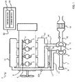
- FIG. 1 is a diagram illustrating a configuration example of engine 2 and ECU 62 according to an embodiment.
- Engine 2 is a diesel engine having four cylinders 3.
- Engine 2 may be a multiple cylinder engine other than 4 cylinders, or may be a single cylinder engine.
- Injectors also referred to as a fuel injection valve
- Injectors 4 are associated with respective cylinders 3, and inject fuel supplied from common rail 5 into respective combustion chambers of cylinders 3.
- High-pressure side intake pipe 11 is connected to an outlet of compressor 9. High-pressure side intake pipe 11 is connected to a downstream end of EGR pipe 15. High-pressure side intake pipe 11 is connected to intake manifold 12.
- intake air air from atmosphere taken from air filter 6 (hereinafter, referred to as intake air) is compressed by compressor 9 through intake pipe 7 into high-pressure intake air. Then, intake air that flows into high-pressure side intake pipe 11 from compressor 9 is mixed with EGR gas from EGR pipe 15. This fuel-air mixture is hereinafter referred to as "working gas”. The working gas flows into the respective combustion chambers of cylinders 3 through intake manifold 12.
- High-pressure side exhaust pipe 14 is connected to exhaust manifold 13.
- EGR pipe 15 is connected to high-pressure side exhaust pipe 14.
- EGR cooler 16 that cools EGR gas
- EGR valve 17 that adjusts a flow rate of EGR gas flowing into high-pressure side intake pipe 11 are provided in EGR pipe 15.
- the "flow rate" means a mass flow rate.
- An inlet of turbine 10 of turbocharger 8 is connected to high-pressure side exhaust pipe 14.
- Exhaust pipe 18 is connected to an outlet of turbine 10.
- Exhaust gas purification apparatus 19 is installed in exhaust pipe 18.
- exhaust gas from each of the combustion chambers of cylinders 3 flows into high-pressure side exhaust pipe 14 from exhaust manifold 13.
- a part of this exhaust gas (EGR gas) flows into high-pressure side intake pipe 11 through EGR pipe 15.
- exhaust gas that flows into turbine 10 passes through exhaust pipe 18 into exhaust gas purification apparatus 19. Exhaust gas purified by exhaust gas purification apparatus 19 is exhausted outside a vehicle.
- Intake oxygen concentration sensor 204 that detects oxygen concentration of intake air is provided in intake pipe 7.
- An installation place of intake oxygen concentration sensor 204 is not limited to an installation place illustrated in FIG. 1 .
- a detection result of intake oxygen concentration sensor 204 is output to ECU 62.
- ECU 62 has control section 64 and storage section 66.
- ECU 62 has, for example, a CPU (Central Processing Unit) that is an example of control section 64, a storage medium such as a ROM (Read Only Memory) storing a control program and various data, a working memory such as a RAM (Random Access Memory) that are an example of storage section 66, and an input/output port. Details of ECU 62 will be described below (refer to FIG. 9 ).
- CPU Central Processing Unit
- ROM Read Only Memory
- RAM Random Access Memory
- FIG. 2 is a diagram illustrating a configuration example of fuel injection control information generation apparatus 50 according to the embodiment
- Fuel injection control information generation apparatus (hereinafter, referred to as a "SOI control information generation apparatus") 50 is an apparatus for generating fuel injection control information (hereinafter, referred to as "SOI control information") 120.
- SOI control information generation apparatus 50 includes control section 52 and storage section 54.
- Control section 52 is, for example, a CPU.
- the storage section is, for example, a volatile or nonvolatile memory device, and/or a storage device.
- Storage section 54 holds test point information 100.
- Test point information 100 has a plurality of test points constituted of a set of an engine speed, a fuel injection amount, and oxygen concentration.
- the constitution of each test point is not limited to this, and may be, for example, a set of an engine speed and a fuel injection amount, or may be a set further including another kind of information.
- Control section 52 includes SOI control information generation section 56.
- SOI control information generation section 56 generates fuel injection control information (referred to as "SOI control information") 120 for each test point included in test point information 100, fuel injection control information 120 being obtained by associating an engine speed, a fuel injection amount, and oxygen concentration at each test point with fuel injection timing at which an index pertaining to a total amount of a fuel consumption rate and an NOx emission amount is the smallest (referred to as "optimum SOI") at the test point.
- SOI control information generation section 56 may be a computer program.
- SOI control information 120 is used in ECU 62.
- ECU 62 determines fuel injection timing on the basis of this SOI control information 120, so that both increase in the NOx emission amount and deterioration of the fuel consumption rate are adequately suppressed.
- FIG. 3 Details of the optimum SOI will be described in FIG. 3 described below. A method for calculating the optimum SOI will be described below. Details of a process of SOI control information generation section 56 will be described in FIG. 4 described below. Details of SOI control information 120 will be described in FIG. 7 or FIG. 8 described below.
- FIG. 3 is a diagram for illustrating the optimum SOI.
- the NOx emission amount and the fuel consumption rate are in the trade-off relationship that when the SOI is retarded, while NOx emission amount 1004 decreases, fuel consumption rate 1002 increases (deteriorates), and when the SOI is advanced, while fuel consumption rate 1002 decreases (improves), the NOx emission amount increases.
- a unit of a value of the SOI is a crank angle (deg CA).
- Index 1006 of FIG. 3 is a value pertaining to a total amount of fuel consumption rate 1002 and NOx emission amount 1004 when the SOI is changed.
- the optimum SOI is SOI at which this index 1006 is the smallest. Therefore, fuel is injected at the optimum SOI, so that it is possible to minimize the total amount of fuel consumption rate 1002 and NOx emission amount 1004. In other words, it is possible to adequately suppress both increase of an NOx emission amount and deterioration of a fuel consumption rate.
- the optimum SOI can be expressed like the following expression 1.
- the "NOx" of expression 1 is a model expression of NOx emission
- the "FC” is a model expression of a fuel consumption rate
- the "C” is a predetermined coefficient.
- expression 1 is a calculation expression of the optimum SOI at which the index pertaining to the total amount of the fuel consumption rate and the NOx emission amount is the smallest.
- Expression 1 can be replaced with a differential equation of the SOI as expressed in the following expression 2.
- C ⁇ dNOx dsoi act + 1 ⁇ C ⁇ dFC dsoi act 0
- variable SOI act that satisfies expression 2 is to calculate the optimum SOI.
- dNOx dsoi act NOx ref ⁇ ⁇ O 2 ⁇ O 2 , ref ⁇ _ O 2 ⁇ ⁇ rail ⁇ P rail ⁇ P rail , ref + 1 ⁇ ⁇ clt ⁇ T clt ⁇ P clt , ref + 1 ⁇ T inm T inm , ref ⁇ inm ⁇ ⁇ soi ⁇ e ⁇ soi ⁇ soi act ⁇ ⁇ soi ⁇ soi ref
- the "NOx ref” denotes an NOx reference value
- the " ⁇ O2” denotes oxygen concentration
- the " ⁇ O2 denotes an oxygen concentration reference value
- the "SOI act” denotes a SOI value
- the "SOI ref” denotes a SOI reference value
- the "P rail” denotes common rail pressure
- the "P rail, ref “ denotes a common rail pressure reference value
- the "T clt denotes a water temperature value
- the "T inm denotes an intake manifold temperature value
- the "T inm, rer " denotes an intake manifold temperature reference value
- the " ⁇ _O2 " and the " ⁇ inm” each denote an exponent term (parameter)
- the " ⁇ soi ", the " ⁇ rail “ and the “ ⁇ clt” each denote a coefficient.
- the following expression 4 is an expression obtained by differentiating a model expression (torque model expression) of fuel consumption with respect to the variable SOI act .
- dFC dsoi act m ⁇ fuel ⁇ 60 Ne ⁇ 2 ⁇ ⁇ ⁇ 10 ⁇ 3 ⁇ ⁇ 1 T ref + ⁇ T soi 2 ⁇ d ⁇ T soi dsoi act
- the "m fuel” denotes a fuel flow rate value
- the "T ref” denotes a reference torque value
- the " ⁇ T soi” denotes a torque change value with respect to SOI change
- the "Ne” denotes an engine speed.
- variable SOI act when values are substituted in respective variables other than the variable SOI act , and these are substituted in expression 2, the variable SOI act can be calculated. This calculated variable SOI act reaches the optimum SOI to the values substituted in the respective variables of expression 3 and expression 4.
- SOI control information generation section 56 calculates optimum SOI by changing the value of each variable, and associates the value of each variable at this time with the calculated optimum SOI to generate SOI control information 120.
- At least one of the variables corresponds to at least one of the engine speed, the fuel injection amount, and the oxygen concentration.
- the value of a variable other than the above may be a value determined with determination of at least one of the engine speed, the fuel injection amount and the oxygen concentration, or may be a value measured in a test run, simulation or the like.
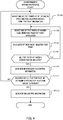
- FIG. 4 is a flowchart illustrating a process example of SOI control information generation section 56.
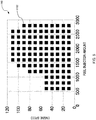
- test point information 100 includes a plurality of test points 1102 of an obtainable set of the engine speed and the fuel injection amount, as illustrated in graph 1100 of FIG. 5 .
- the obtainable set is a set that can be actually generated during vehicle running.
- test point information 100 does not include a set that cannot be generated during vehicle running, for example, a set in which the fuel injection amount is extremely small, and/or a set in which the engine speed is extremely large.
- SOI control information generation section 56 selects one of test points of oxygen concentration, from test point information 100.
- test point information 100 includes a plurality of test points of obtainable oxygen concentration.
- SOI control information generation section 56 calculates optimum SOI for the test point of the set of the engine speed and the fuel injection amount selected in ST100, and the test point of the oxygen concentration selected in ST102, on the basis of the above expressions.
- SOI control information generation section 56 may substitute a value different for each set of the engine speed and the fuel injection amount selected in ST100 in the coefficient "C" of expression 2.
- SOI control information generation section 56 determines whether or not selection of all obtainable test points of the oxygen concentration is finished in ST102 to the test point selected in ST100.
- SOI control information generation section 56 returns to ST102, and selects one of the remaining test points of the oxygen concentration.
- SOI control information generation section 56 In a case in which selection of all the test points of the oxygen concentration is finished (ST106: YES), SOI control information generation section 56 generates intermediate SOI control information 1200 illustrated in FIG. 6 in ST108.
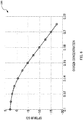
- Intermediate SOI control information 1200 is information indicating change of optimum SOI when a test point of oxygen concentration is changed at the test point of the engine speed and the fuel injection amount selected in ST100.
- Intermediate SOI control information 1200 may be information in which the test point of oxygen concentration is associated with the optimum SOI in a one-to-one manner, or may be information of a function that expresses the change of the optimum SOI to the change of the test point of the oxygen concentration.
- SOI control information generation section 56 determines whether or not selection of all the obtainable test points of the set is finished in ST100.
- SOI control information generation section 56 returns to ST100, and selects one of the test point of the remaining set.
- SOI control information generation section 56 In a case in which the selection of the test points of all sets are finished (ST110: YES), SOI control information generation section 56 generates SOI control information 120 illustrated in FIG. 7 or FIG. 8 described below, on the basis of a plurality of pieces of intermediate SOI control information 1200 generated in ST108, in ST112, and this process is finished.
- SOI control information 120 illustrated in FIG. 7 or FIG. 8 described below is generated.
- FIG. 7 is a diagram illustrating an example of SOI control information 120.
- SOI control information 120A of FIG. 7 is a three-dimensional map information in which a plurality of the optimum SOI are associated with a plurality of the test points that are the sets of the fuel injection amount, the engine speed and the oxygen concentration.
- SOI control information generation section 56 generates SOI control information 120A by associating each set of the fuel injection amount and the engine speed with intermediate SOI control information 1200 of FIG. 6 corresponding to the set.
- ECU 62 can identify one optimum SOI to one set of a fuel injection amount and an engine speed determined on the basis of information collected from various sensors, and oxygen concentration determined on the basis of information collected from intake oxygen concentration sensor 204, with reference to SOI control information 120A of interest.
- FIG. 8 is a diagram illustrating a modification of SOI control information 120.
- SOI control information 120B is logic information (information of approximate expression) for calculating one optimum SOI value to the set of the fuel injection amount, the engine speed and the oxygen concentration, as illustrated in the following expression 5, and coefficient maps 1401, 1402 and 1403 of FIG. 8 .
- SOI opt K 1 ⁇ O 2 ⁇ K 2 2 + K 3
- the "SOI opt” denotes the optimum SOI value
- the " ⁇ O2 " denotes the oxygen concentration
- K 1 ", “K 2 ", and “K 3 " each denotes a coefficient determined according to the engine speed and the fuel injection amount, as illustrated by coefficient K 1 map 1401, coefficient K 2 map 1402, and coefficient K 3 map 1403.
- SOI control information generation section 56 generates SOI control information 120B by associating coefficient K 1 map 1401, coefficient K 2 map 1402 and coefficient K 3 map 1403 with the respective sets of the fuel injection amount and the engine speed such that expression 5 is approximated to a function of intermediate SOI control information 1200 of FIG. 6 .
- ECU 62 identifies coefficient K 1 , coefficient K 2 , and coefficient K 3 to the set of the fuel injection amount and the engine speed determined on the basis of the information collected from the various sensors with reference to coefficient K 1 map 1401, coefficient K 2 map 1402, and coefficient K 3 map 1403.
- ECU 62 substitutes oxygen concentration determined on the basis of the information collected from intake oxygen concentration sensor 204 in the " ⁇ O2 " of expression 5, substitutes coefficient K 1 , coefficient K 2 and coefficient K 3 identified above in the "K 1 ", “K 2 “, and “K 3 " of expression 5, respectively, and calculates the SOI opt (optimum SOI).
- ECU 62 can identify one optimum SOI to one set of oxygen concentration determined on the basis of the fuel injection amount and the engine speed determined on the basis of the information collected from various sensors, and the information collected from intake oxygen concentration sensor 204.
- SOI control information 120A of FIG. 7 has a merit that accuracy of the optimum SOI is higher than SOI control information 120B of FIG. 8 .
- SOI control information 120B of FIG. 8 has a merit that an data amount is smaller than SOI control information 120A of FIG. 7 .
- This SOI control information 120 is used when ECU 62 controls fuel injection. Now, this ECU 62 will be described.
- FIG. 9 is a diagram illustrating a configuration example of ECU 62.
- ECU 62 includes control section 64 and storage section 66.
- Control section 64 is, for example, an LSI.
- Storage section 66 is, for example, a nonvolatile memory device.
- Storage section 66 holds SOI control information 120 generated by SOI control information generation apparatus 50.
- Control section 64 includes optimum fuel injection timing determination section (referred to as "optimum SOI determination section") 68.
- optimum SOI determination section 68 determines an engine speed and a fuel injection amount on the basis of the information collected from various sensors. Additionally, optimum SOI determination section 68 recognizes oxygen concentration on the basis of the information collected from intake oxygen concentration sensor 204.
- Optimum SOI determination section 68 determines optimum SOI to the determined engine speed and fuel injection amount, and the recognized oxygen concentration, on the basis of SOI control information 120 inside storage section 66.
- Optimum SOI determination section 68 controls injectors 4 such that fuel is injected at the determined optimum SOI. Consequently, fuel is injected such that both increase in the NOx emission amount and deterioration of the fuel consumption rate are adequately suppressed.
- Optimum SOI determination section 68 can identify optimum SOI at which both the increase in the NOx emission amount and the deterioration of the fuel consumption rate are adequately suppressed, even when either SOI control information 120A of FIG. 7 or SOI control information 120B of FIG. 8 is used.
- SOI control information 120 generated on the basis of this embodiment is applicable in any running state.
- the SOI control information is more effectively applicable in an transition state in which speed change is large, for example, during acceleration or deceleration.
- a reason thereof will be described with reference to FIG. 10 .
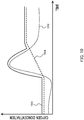
- FIG. 10 is a diagram for illustrating SOI control in a transition state.
- ECU 62 controls EGR valve 17 or SOI such that the oxygen concentration in each of cylinders 3 reaches oxygen concentration target value 1506 set near base target value 1504, in a steady state in which speed change is small, for example, during running at a constant speed.
- Base target value 1504 is oxygen concentration that implements a theoretical air-fuel ratio at a steady time.
- ECU 62 forcibly closes EGR valve 17 to increase the oxygen concentration in each of cylinders 3, in the transition state. This is because in the transition state, the oxygen concentration in each of cylinders 3 tends to lower due to delay of increase response of an intake amount to increase response of a fuel injection amount, and when EGR valve 17 is not closed, soot or the like is generated due to incomplete combustion.
- Smoke Limit 1502 of FIG. 10 indicates a limit value thereof, and the oxygen concentration in each of cylinders 3 needs to be controlled to exceed Smoke Limit 1502 in order to prevent generation of soot or the like.
- the SOI may be determined on the basis of SOI control information 120, and in a case in which the steady state is detected, the SOI may be determined by an existing method.
- the present disclosure is usable for fuel control of a vehicle.
Landscapes
- Engineering & Computer Science (AREA)
- Chemical & Material Sciences (AREA)
- Combustion & Propulsion (AREA)
- Mechanical Engineering (AREA)
- General Engineering & Computer Science (AREA)
- Combined Controls Of Internal Combustion Engines (AREA)
- Electrical Control Of Air Or Fuel Supplied To Internal-Combustion Engine (AREA)
Abstract
Description
- The present disclosure relates to a fuel injection control information generation apparatus, and a control apparatus.
- In recent years, there has been a demand for achieving both reduction in a nitrogen oxide (referred to as "NOx") emission amount and improvement of a fuel consumption rate.
PTL 1 discloses that when fuel injection timing (referred to as "SOI (Start Of Injection)") is retarded, and a combustion temperature in a cylinder of an engine is lowered, an NOx emission amount is reduced, but when SOI is retarded, the fuel consumption rate is deteriorated, that is, the NOx emission amount and the fuel consumption rate are in a trade-off relationship with respect to change of the SOI. -
PTL 1
Japanese Patent Application Laid-Open No.2010-271801 - As described above, the NOx emission amount and the fuel consumption rate are in the trade-off relationship with respect to the change of SOI. Therefore, adequate suppression of both increase in an NOx emission amount and deterioration of a fuel consumption rate is required.
- An object of the present disclosure is to adequately suppress both the increase in the NOx emission amount and the deterioration of the fuel consumption rate.
- A fuel injection control information generation apparatus according to one embodiment of the present disclosure includes: a test point information storage section that holds test point information including a plurality of test points constituted of a set of an engine speed, a fuel injection amount, and oxygen concentration; and a control information generation section that generates, for each of the test points included in the test point information, fuel injection control information in which the engine speed, the fuel injection amount, and the oxygen concentration at the test point are associated with an optimum fuel injection timing at which an index pertaining to a total amount of a fuel consumption rate and an NOx emission amount at the test point reaches the smallest.
- A control apparatus according to one embodiment of the present disclosure includes: a control information storage section that holds the fuel injection control information generated by the fuel injection control information generation apparatus described above; and a control section that controls a fuel injection timing of an internal-combustion engine on the basis of the fuel injection control information.
- According to the present disclosure, it is possible to adequately suppress both increase in an NOx emission amount and deterioration of a fuel consumption rate.
-
-
FIG. 1 is a diagram illustrating a configuration example of an engine and an ECU according to an embodiment; -
FIG. 2 is a diagram illustrating a configuration example of a fuel injection control information generation apparatus according to the embodiment; -
FIG. 3 is a diagram for illustrating optimum SOI; -
FIG. 4 is a flowchart illustrating a process example of a SOI control information generation section; -
FIG. 5 is a diagram illustrating an example of a test point of a set of an engine speed and a fuel injection amount; -
FIG. 6 is a diagram illustrating an example of intermediate SOI control information; -
FIG. 7 is a diagram illustrating an example of SOI control information; -
FIG. 8 is a diagram illustrating a modification of the SOI control information; -
FIG. 9 is a diagram illustrating a configuration example of the ECU; and -
FIG. 10 is a diagram for illustrating SOI control at a transition time. - Hereinafter, an embodiment according to the present disclosure will be described with reference to the accompanying drawings. In the following description, in a case in which the same kind of components are distinguished in the description, reference numerals are used like "
SOI control information 120A", and "SOI control information 120B", and in a case in which the same kind of components are described without being distinguished, only common numerals among reference numerals may be used like "SOI control information 120". -
FIG. 1 is a diagram illustrating a configuration example ofengine 2 andECU 62 according to an embodiment. - First,
engine 2 will be described. -
Engine 2 is a diesel engine having fourcylinders 3.Engine 2 may be a multiple cylinder engine other than 4 cylinders, or may be a single cylinder engine. - Injectors (also referred to as a fuel injection valve) 4 are associated with
respective cylinders 3, and inject fuel supplied fromcommon rail 5 into respective combustion chambers ofcylinders 3. - To
air filter 6, an upstream end ofintake pipe 7 is connected. A downstream end ofintake pipe 7 is connected to an inlet ofcompressor 9 ofturbocharger 8. High-pressure side intake pipe 11 is connected to an outlet ofcompressor 9. High-pressure side intake pipe 11 is connected to a downstream end ofEGR pipe 15. High-pressure side intake pipe 11 is connected tointake manifold 12. - With such a configuration, air from atmosphere taken from air filter 6 (hereinafter, referred to as intake air) is compressed by
compressor 9 throughintake pipe 7 into high-pressure intake air. Then, intake air that flows into high-pressure side intake pipe 11 fromcompressor 9 is mixed with EGR gas from EGRpipe 15. This fuel-air mixture is hereinafter referred to as "working gas". The working gas flows into the respective combustion chambers ofcylinders 3 throughintake manifold 12. - High-pressure
side exhaust pipe 14 is connected toexhaust manifold 13. EGRpipe 15 is connected to high-pressureside exhaust pipe 14. EGRcooler 16 that cools EGR gas, andEGR valve 17 that adjusts a flow rate of EGR gas flowing into high-pressure side intake pipe 11 are provided in EGRpipe 15. In this embodiment, the "flow rate" means a mass flow rate. - An inlet of
turbine 10 ofturbocharger 8 is connected to high-pressureside exhaust pipe 14.Exhaust pipe 18 is connected to an outlet ofturbine 10. Exhaustgas purification apparatus 19 is installed inexhaust pipe 18. - With such a configuration, exhaust gas from each of the combustion chambers of
cylinders 3 flows into high-pressureside exhaust pipe 14 fromexhaust manifold 13. A part of this exhaust gas (EGR gas) flows into high-pressure side intake pipe 11 through EGRpipe 15. On the other hand, exhaust gas that flows intoturbine 10 passes throughexhaust pipe 18 into exhaustgas purification apparatus 19. Exhaust gas purified by exhaustgas purification apparatus 19 is exhausted outside a vehicle. - Intake
oxygen concentration sensor 204 that detects oxygen concentration of intake air is provided inintake pipe 7. An installation place of intakeoxygen concentration sensor 204 is not limited to an installation place illustrated inFIG. 1 . - A detection result of intake
oxygen concentration sensor 204 is output toECU 62. - Thus,
engine 2 is described. - Now, ECU 62 will be described.
- ECU 62 has
control section 64 andstorage section 66. ECU 62 has, for example, a CPU (Central Processing Unit) that is an example ofcontrol section 64, a storage medium such as a ROM (Read Only Memory) storing a control program and various data, a working memory such as a RAM (Random Access Memory) that are an example ofstorage section 66, and an input/output port. Details of ECU 62 will be described below (refer toFIG. 9 ). -
FIG. 2 is a diagram illustrating a configuration example of fuel injection controlinformation generation apparatus 50 according to the embodiment - Fuel injection control information generation apparatus (hereinafter, referred to as a "SOI control information generation apparatus") 50 is an apparatus for generating fuel injection control information (hereinafter, referred to as "SOI control information") 120.
- SOI control
information generation apparatus 50 includescontrol section 52 andstorage section 54.Control section 52 is, for example, a CPU. The storage section is, for example, a volatile or nonvolatile memory device, and/or a storage device. -
Storage section 54 holdstest point information 100. -
Test point information 100 has a plurality of test points constituted of a set of an engine speed, a fuel injection amount, and oxygen concentration. The constitution of each test point is not limited to this, and may be, for example, a set of an engine speed and a fuel injection amount, or may be a set further including another kind of information. -
Control section 52 includes SOI controlinformation generation section 56. SOI controlinformation generation section 56 generates fuel injection control information (referred to as "SOI control information") 120 for each test point included intest point information 100, fuelinjection control information 120 being obtained by associating an engine speed, a fuel injection amount, and oxygen concentration at each test point with fuel injection timing at which an index pertaining to a total amount of a fuel consumption rate and an NOx emission amount is the smallest (referred to as "optimum SOI") at the test point. SOI controlinformation generation section 56 may be a computer program. -
SOI control information 120 is used inECU 62.ECU 62 determines fuel injection timing on the basis of thisSOI control information 120, so that both increase in the NOx emission amount and deterioration of the fuel consumption rate are adequately suppressed. - Details of the optimum SOI will be described in
FIG. 3 described below. A method for calculating the optimum SOI will be described below. Details of a process of SOI controlinformation generation section 56 will be described inFIG. 4 described below. Details ofSOI control information 120 will be described inFIG. 7 orFIG. 8 described below. -
FIG. 3 is a diagram for illustrating the optimum SOI. - As illustrated in
graph 1000 ofFIG. 3 , the NOx emission amount and the fuel consumption rate are in the trade-off relationship that when the SOI is retarded, whileNOx emission amount 1004 decreases,fuel consumption rate 1002 increases (deteriorates), and when the SOI is advanced, whilefuel consumption rate 1002 decreases (improves), the NOx emission amount increases. A unit of a value of the SOI is a crank angle (deg CA). -
Index 1006 ofFIG. 3 is a value pertaining to a total amount offuel consumption rate 1002 andNOx emission amount 1004 when the SOI is changed. The optimum SOI is SOI at which thisindex 1006 is the smallest. Therefore, fuel is injected at the optimum SOI, so that it is possible to minimize the total amount offuel consumption rate 1002 andNOx emission amount 1004. In other words, it is possible to adequately suppress both increase of an NOx emission amount and deterioration of a fuel consumption rate. - Now, the method for calculating the optimum SOI will be described.
- The optimum SOI can be expressed like the
following expression 1.
In the expression, the "NOx" ofexpression 1 is a model expression of NOx emission, the "FC" is a model expression of a fuel consumption rate, and the "C" is a predetermined coefficient. As described inFIG. 3 ,expression 1 is a calculation expression of the optimum SOI at which the index pertaining to the total amount of the fuel consumption rate and the NOx emission amount is the smallest. -
Expression 1 can be replaced with a differential equation of the SOI as expressed in the followingexpression 2.
- That is, to obtain variable SOIact that satisfies
expression 2 is to calculate the optimum SOI. - The following
expression 3 is an expression obtained by differentiating the model expression of the NOx emission with respect to the variable SOIact.
- In the expression, the "NOxref" denotes an NOx reference value, the "ΨO2" denotes oxygen concentration, the "ΨO2, ref" denotes an oxygen concentration reference value, the "SOIact" denotes a SOI value, the "SOIref" denotes a SOI reference value, the "Prail" denotes common rail pressure, the "Prail, ref" denotes a common rail pressure reference value, the "Tclt" denotes a water temperature value, the "Tclt, ref" denotes a water temperature reference value, the "Tinm" denotes an intake manifold temperature value, the "Tinm, rer" denotes an intake manifold temperature reference value, the "α_O2" and the "αinm" each denote an exponent term (parameter), and the "βsoi", the "βrail" and the "βclt" each denote a coefficient.
- The following
expression 4 is an expression obtained by differentiating a model expression (torque model expression) of fuel consumption with respect to the variable SOIact.
- Herein, the "mfuel" denotes a fuel flow rate value, the "Tref" denotes a reference torque value, the "ΔTsoi" denotes a torque change value with respect to SOI change, and the "Ne" denotes an engine speed.
- In
expression 3 andexpression 4, when values are substituted in respective variables other than the variable SOIact, and these are substituted inexpression 2, the variable SOIact can be calculated. This calculated variable SOIact reaches the optimum SOI to the values substituted in the respective variables ofexpression 3 andexpression 4. - SOI control
information generation section 56 calculates optimum SOI by changing the value of each variable, and associates the value of each variable at this time with the calculated optimum SOI to generateSOI control information 120. At least one of the variables corresponds to at least one of the engine speed, the fuel injection amount, and the oxygen concentration. The value of a variable other than the above may be a value determined with determination of at least one of the engine speed, the fuel injection amount and the oxygen concentration, or may be a value measured in a test run, simulation or the like. -
FIG. 4 is a flowchart illustrating a process example of SOI controlinformation generation section 56. - In ST100, SOI control
information generation section 56 selects one of test points of a set of the engine speed and the fuel injection amount, fromtest point information 100.Test point information 100 includes a plurality oftest points 1102 of an obtainable set of the engine speed and the fuel injection amount, as illustrated ingraph 1100 ofFIG. 5 . The obtainable set is a set that can be actually generated during vehicle running. In other words, testpoint information 100 does not include a set that cannot be generated during vehicle running, for example, a set in which the fuel injection amount is extremely small, and/or a set in which the engine speed is extremely large. - In ST102, SOI control
information generation section 56 selects one of test points of oxygen concentration, fromtest point information 100. Similarly to the above,test point information 100 includes a plurality of test points of obtainable oxygen concentration. - In ST104, SOI control
information generation section 56 calculates optimum SOI for the test point of the set of the engine speed and the fuel injection amount selected in ST100, and the test point of the oxygen concentration selected in ST102, on the basis of the above expressions. SOI controlinformation generation section 56 may substitute a value different for each set of the engine speed and the fuel injection amount selected in ST100 in the coefficient "C" ofexpression 2. - In ST106, SOI control
information generation section 56 determines whether or not selection of all obtainable test points of the oxygen concentration is finished in ST102 to the test point selected in ST100. - In a case in which an unselected test point of the oxygen concentration remains (ST106: NO), SOI control
information generation section 56 returns to ST102, and selects one of the remaining test points of the oxygen concentration. - In a case in which selection of all the test points of the oxygen concentration is finished (ST106: YES), SOI control
information generation section 56 generates intermediateSOI control information 1200 illustrated inFIG. 6 in ST108. IntermediateSOI control information 1200 is information indicating change of optimum SOI when a test point of oxygen concentration is changed at the test point of the engine speed and the fuel injection amount selected in ST100. - Intermediate
SOI control information 1200 may be information in which the test point of oxygen concentration is associated with the optimum SOI in a one-to-one manner, or may be information of a function that expresses the change of the optimum SOI to the change of the test point of the oxygen concentration. - In ST110, SOI control
information generation section 56 determines whether or not selection of all the obtainable test points of the set is finished in ST100. - In a case in which a test point of an unselected set remains (ST110: NO), SOI control
information generation section 56 returns to ST100, and selects one of the test point of the remaining set. - In a case in which the selection of the test points of all sets are finished (ST110: YES), SOI control
information generation section 56 generatesSOI control information 120 illustrated inFIG. 7 orFIG. 8 described below, on the basis of a plurality of pieces of intermediateSOI control information 1200 generated in ST108, in ST112, and this process is finished. - With the above processes,
SOI control information 120 illustrated inFIG. 7 orFIG. 8 described below is generated. -
FIG. 7 is a diagram illustrating an example ofSOI control information 120. -
SOI control information 120A ofFIG. 7 is a three-dimensional map information in which a plurality of the optimum SOI are associated with a plurality of the test points that are the sets of the fuel injection amount, the engine speed and the oxygen concentration. - SOI control
information generation section 56 generatesSOI control information 120A by associating each set of the fuel injection amount and the engine speed with intermediateSOI control information 1200 ofFIG. 6 corresponding to the set. -
ECU 62 can identify one optimum SOI to one set of a fuel injection amount and an engine speed determined on the basis of information collected from various sensors, and oxygen concentration determined on the basis of information collected from intakeoxygen concentration sensor 204, with reference to SOI controlinformation 120A of interest. -
FIG. 8 is a diagram illustrating a modification ofSOI control information 120. -
SOI control information 120B is logic information (information of approximate expression) for calculating one optimum SOI value to the set of the fuel injection amount, the engine speed and the oxygen concentration, as illustrated in the followingexpression 5, andcoefficient maps FIG. 8 .
Inexpression 5, the "SOIopt" denotes the optimum SOI value, the "ΨO2" denotes the oxygen concentration, the "K1", "K2", and "K3" each denotes a coefficient determined according to the engine speed and the fuel injection amount, as illustrated by coefficient K1 map 1401, coefficient K2 map 1402, and coefficient K3 map 1403. - SOI control
information generation section 56 generatesSOI control information 120B by associating coefficient K1 map 1401, coefficient K2 map 1402 and coefficient K3 map 1403 with the respective sets of the fuel injection amount and the engine speed such thatexpression 5 is approximated to a function of intermediateSOI control information 1200 ofFIG. 6 . -
ECU 62 identifies coefficient K1, coefficient K2, and coefficient K3 to the set of the fuel injection amount and the engine speed determined on the basis of the information collected from the various sensors with reference to coefficient K1 map 1401, coefficient K2 map 1402, and coefficient K3 map 1403. -
ECU 62 substitutes oxygen concentration determined on the basis of the information collected from intakeoxygen concentration sensor 204 in the "ΨO2" ofexpression 5, substitutes coefficient K1, coefficient K2 and coefficient K3 identified above in the "K1", "K2", and "K3" ofexpression 5, respectively, and calculates the SOIopt (optimum SOI). - With the above processes,
ECU 62 can identify one optimum SOI to one set of oxygen concentration determined on the basis of the fuel injection amount and the engine speed determined on the basis of the information collected from various sensors, and the information collected from intakeoxygen concentration sensor 204. -
SOI control information 120A ofFIG. 7 has a merit that accuracy of the optimum SOI is higher thanSOI control information 120B ofFIG. 8 .SOI control information 120B ofFIG. 8 has a merit that an data amount is smaller thanSOI control information 120A ofFIG. 7 . - This
SOI control information 120 is used whenECU 62 controls fuel injection. Now, thisECU 62 will be described. -
FIG. 9 is a diagram illustrating a configuration example ofECU 62. -
ECU 62 includescontrol section 64 andstorage section 66.Control section 64 is, for example, an LSI.Storage section 66 is, for example, a nonvolatile memory device. -
Storage section 66 holdsSOI control information 120 generated by SOI controlinformation generation apparatus 50. -
Control section 64 includes optimum fuel injection timing determination section (referred to as "optimum SOI determination section") 68. OptimumSOI determination section 68 determines an engine speed and a fuel injection amount on the basis of the information collected from various sensors. Additionally, optimumSOI determination section 68 recognizes oxygen concentration on the basis of the information collected from intakeoxygen concentration sensor 204. - Optimum
SOI determination section 68 determines optimum SOI to the determined engine speed and fuel injection amount, and the recognized oxygen concentration, on the basis ofSOI control information 120 insidestorage section 66. - Optimum
SOI determination section 68controls injectors 4 such that fuel is injected at the determined optimum SOI. Consequently, fuel is injected such that both increase in the NOx emission amount and deterioration of the fuel consumption rate are adequately suppressed. - Optimum
SOI determination section 68 can identify optimum SOI at which both the increase in the NOx emission amount and the deterioration of the fuel consumption rate are adequately suppressed, even when eitherSOI control information 120A ofFIG. 7 orSOI control information 120B ofFIG. 8 is used. -
SOI control information 120 generated on the basis of this embodiment is applicable in any running state. However, the SOI control information is more effectively applicable in an transition state in which speed change is large, for example, during acceleration or deceleration. Hereinafter, a reason thereof will be described with reference toFIG. 10 . -
FIG. 10 is a diagram for illustrating SOI control in a transition state. -
ECU 62controls EGR valve 17 or SOI such that the oxygen concentration in each ofcylinders 3 reaches oxygenconcentration target value 1506 set nearbase target value 1504, in a steady state in which speed change is small, for example, during running at a constant speed.Base target value 1504 is oxygen concentration that implements a theoretical air-fuel ratio at a steady time. -
ECU 62 forcibly closesEGR valve 17 to increase the oxygen concentration in each ofcylinders 3, in the transition state. This is because in the transition state, the oxygen concentration in each ofcylinders 3 tends to lower due to delay of increase response of an intake amount to increase response of a fuel injection amount, and whenEGR valve 17 is not closed, soot or the like is generated due to incomplete combustion.Smoke Limit 1502 ofFIG. 10 indicates a limit value thereof, and the oxygen concentration in each ofcylinders 3 needs to be controlled to exceedSmoke Limit 1502 in order to prevent generation of soot or the like. - However, when
EGR valve 17 is thus closed, the combustion temperature in each ofcylinders 3 increases, and therefore the NOx emission amount increases. The SOI should be retarded in order to suppress increase of the combustion temperature in each ofcylinders 3. However, as described above inFIG. 3 , when the SOI is retarded, the fuel consumption rate is deteriorated. - That is, conventionally, it is unclear how much the SOI should be retarded in order to adequately suppress both the increase of the NOx emission amount and the deterioration of the fuel consumption rate. However, by using
SOI control information 120 according to this embodiment, these can be adequately suppressed. - Only when
ECU 62 detects the transition state, the SOI may be determined on the basis ofSOI control information 120, and in a case in which the steady state is detected, the SOI may be determined by an existing method. - The above embodiments are merely examples embodying the invention for implementing the present disclosure, and the technological scope should not be considered to be restrictive by them. That is, the present disclosure can be implemented in various forms without departing from the scope, or essential characteristics thereof.
- The present application is based on a Japanese patent application (Japanese Patent Application No.
2016-235921 - The present disclosure is usable for fuel control of a vehicle.
-
- 2 Engine
- 3 Cylinder
- 4 Injector
- 50 Fuel injection control information generation apparatus
- 52 Control section
- 54 Storage section
- 56 Fuel injection control information generation section
- 62 ECU
- 64 Control section
- 66 Storage section
- 68 Optimum fuel injection timing determination section
- 100 Test point information
- 120, 120A, 120B Fuel injection control information
- 204 Intake oxygen concentration sensor
- 1200 Intermediate fuel injection control information
- 1401 Coefficient K1 map
- 1402 Coefficient K2 map
- 1403 Coefficient K3 map
Claims (5)
- A fuel injection control information generation apparatus, comprising:a test point information storage section that holds test point information including a plurality of test points constituted of a set of an engine speed, a fuel injection amount, and oxygen concentration; anda control information generation section that generates, for each of the test points included in the test point information, fuel injection control information in which the engine speed, the fuel injection amount, and the oxygen concentration at the test point are associated with an optimum fuel injection timing at which an index pertaining to a total amount of a fuel consumption rate and an NOx emission amount at the test point reaches the smallest.
- The fuel injection control information generation apparatus according to claim 1, wherein
the fuel injection control information is map information in which the optimum fuel injection timing is associated with each of the plurality of test points. - The fuel injection control information generation apparatus according to claim 1, wherein
the fuel injection control information is logic information indicating an approximate expression for calculating the optimum fuel injection timing on the basis of the engine speed, the fuel injection amount and the oxygen concentration, the approximate expression being derived from correspondence relation between each of the plurality of test points and the optimum fuel injection timing. - A control apparatus, comprising:a control information storage section that holds the fuel injection control information generated by the fuel injection control information generation apparatus according to claim 1; anda control section that controls a fuel injection timing of an internal-combustion engine on the basis of the fuel injection control information.
- The control apparatus according to claim 4, wherein
the control section controls the fuel injection timing of the internal-combustion engine on the basis of the fuel injection control information, only when an operating state of the internal-combustion engine is in a transition state,.
Applications Claiming Priority (2)
| Application Number | Priority Date | Filing Date | Title |
|---|---|---|---|
| JP2016235921A JP6755167B2 (en) | 2016-12-05 | 2016-12-05 | Control device |
| PCT/JP2017/043520 WO2018105567A1 (en) | 2016-12-05 | 2017-12-04 | Fuel injection control information generation device and control device |
Publications (3)
| Publication Number | Publication Date |
|---|---|
| EP3550129A1 true EP3550129A1 (en) | 2019-10-09 |
| EP3550129A4 EP3550129A4 (en) | 2019-11-13 |
| EP3550129B1 EP3550129B1 (en) | 2023-03-22 |
Family
ID=62492318
Family Applications (1)
| Application Number | Title | Priority Date | Filing Date |
|---|---|---|---|
| EP17877703.3A Active EP3550129B1 (en) | 2016-12-05 | 2017-12-04 | Fuel injection control information generation device and control device |
Country Status (5)
| Country | Link |
|---|---|
| US (1) | US10774764B2 (en) |
| EP (1) | EP3550129B1 (en) |
| JP (1) | JP6755167B2 (en) |
| CN (1) | CN110023611B (en) |
| WO (1) | WO2018105567A1 (en) |
Family Cites Families (14)
| Publication number | Priority date | Publication date | Assignee | Title |
|---|---|---|---|---|
| JPH11159356A (en) * | 1997-09-24 | 1999-06-15 | Denso Corp | Valve timing control device for internal combustion engine |
| JP2002004912A (en) | 2000-06-27 | 2002-01-09 | Toyota Motor Corp | Cars based on lean / rich driving combination maps |
| JP2002206448A (en) * | 2000-11-08 | 2002-07-26 | Denso Corp | Exhaust gas purification device for internal combustion engine |
| JP3951967B2 (en) * | 2002-08-01 | 2007-08-01 | トヨタ自動車株式会社 | Automatic adapting device |
| US6725148B1 (en) * | 2002-10-31 | 2004-04-20 | Csxt Intellectual Properties Corporation | Diesel engine injection timing signal interceptor module |
| JP2009150280A (en) * | 2007-12-19 | 2009-07-09 | Toyota Central R&D Labs Inc | Control device for compression ignition type internal combustion engine |
| JP2009167836A (en) | 2008-01-11 | 2009-07-30 | Toyota Motor Corp | Fuel injection control device for internal combustion engine |
| JP4928484B2 (en) * | 2008-02-29 | 2012-05-09 | 株式会社小野測器 | Method, computer and program for calculating engine design variables |
| JP5115464B2 (en) * | 2008-12-15 | 2013-01-09 | トヨタ自動車株式会社 | Device for setting control parameters of internal combustion engine |
| JP5216685B2 (en) | 2009-05-19 | 2013-06-19 | 株式会社小野測器 | Multi-objective optimal solution set calculation apparatus, multi-objective optimal solution set calculation method, and multi-objective optimal solution set calculation program |
| JP5143170B2 (en) * | 2010-03-17 | 2013-02-13 | 日立オートモティブシステムズ株式会社 | Control method for internal combustion engine |
| US9599042B2 (en) * | 2010-10-28 | 2017-03-21 | International Engine Intellectual Property Company, Llc. | Start of injection timing |
| JP6326260B2 (en) * | 2014-03-28 | 2018-05-16 | 三菱重工業株式会社 | Control device for internal combustion engine |
| JP6293586B2 (en) * | 2014-06-20 | 2018-03-14 | 三菱重工業株式会社 | Fuel injection valve and fuel injection device |
-
2016
- 2016-12-05 JP JP2016235921A patent/JP6755167B2/en active Active
-
2017
- 2017-12-04 US US16/466,652 patent/US10774764B2/en active Active
- 2017-12-04 EP EP17877703.3A patent/EP3550129B1/en active Active
- 2017-12-04 CN CN201780073680.1A patent/CN110023611B/en active Active
- 2017-12-04 WO PCT/JP2017/043520 patent/WO2018105567A1/en not_active Ceased
Also Published As
| Publication number | Publication date |
|---|---|
| US10774764B2 (en) | 2020-09-15 |
| CN110023611B (en) | 2022-08-12 |
| EP3550129B1 (en) | 2023-03-22 |
| JP6755167B2 (en) | 2020-09-16 |
| WO2018105567A1 (en) | 2018-06-14 |
| EP3550129A4 (en) | 2019-11-13 |
| US20190383223A1 (en) | 2019-12-19 |
| JP2018091242A (en) | 2018-06-14 |
| CN110023611A (en) | 2019-07-16 |
Similar Documents
| Publication | Publication Date | Title |
|---|---|---|
| US9989029B2 (en) | Method and device for determining a charge air mass flow rate | |
| CN103782013B (en) | Method and apparatus for controlling misfire | |
| EP2151567B1 (en) | Cetane number estimating device and method | |
| US7174250B2 (en) | Method for determining an exhaust gas recirculation quantity for an internal combustion engine provided with exhaust gas recirculation | |
| EP3885542A1 (en) | Internal combustion engine control device | |
| EP1862657A1 (en) | Fuel jetting control unit for internal combustion engine | |
| EP3239484A1 (en) | EXHAUST PURIFICATION SYSTEM AND METHOD FOR RESTORING NOx PURIFICATION CAPACITY | |
| US9322357B2 (en) | Soot accumulation model for setpoint modification | |
| US11649779B2 (en) | Control device | |
| EP3029304A1 (en) | Exhaust system state detection device | |
| EP2623753A2 (en) | NOx control | |
| EP2623755A2 (en) | Oxygen concentration setpoint modification | |
| EP3550129B1 (en) | Fuel injection control information generation device and control device | |
| JP5076879B2 (en) | Fuel injection control system for internal combustion engine | |
| EP2623758B1 (en) | Turbocharger control | |
| JP2015190397A (en) | Soot emission estimation device for internal combustion engine | |
| US9328691B2 (en) | Setpoint bank control architecture | |
| CN119630872A (en) | Internal combustion engine control device and state quantity estimation method | |
| US10352222B2 (en) | Control apparatus for internal combustion engine | |
| Sidorow et al. | Model based fault detection of the air and exhaust path of diesel engines including turbocharger models | |
| EP2765290B1 (en) | Method for estimating the temperature of exhaust gas | |
| JP6484531B2 (en) | Air-fuel ratio control method and exhaust purification device | |
| JP2008291811A (en) | Cetane number estimation apparatus and method | |
| Cipollone et al. | Fuel dynamics compensation: on-line identification of Aquino parameters | |
| Sajjad et al. | Ship Propeller Law Transient Cycle: Performance and Emissions |
Legal Events
| Date | Code | Title | Description |
|---|---|---|---|
| STAA | Information on the status of an ep patent application or granted ep patent |
Free format text: STATUS: THE INTERNATIONAL PUBLICATION HAS BEEN MADE |
|
| PUAI | Public reference made under article 153(3) epc to a published international application that has entered the european phase |
Free format text: ORIGINAL CODE: 0009012 |
|
| STAA | Information on the status of an ep patent application or granted ep patent |
Free format text: STATUS: REQUEST FOR EXAMINATION WAS MADE |
|
| 17P | Request for examination filed |
Effective date: 20190604 |
|
| AK | Designated contracting states |
Kind code of ref document: A1 Designated state(s): AL AT BE BG CH CY CZ DE DK EE ES FI FR GB GR HR HU IE IS IT LI LT LU LV MC MK MT NL NO PL PT RO RS SE SI SK SM TR |
|
| A4 | Supplementary search report drawn up and despatched |
Effective date: 20191011 |
|
| RIC1 | Information provided on ipc code assigned before grant |
Ipc: F02D 41/14 20060101ALI20191007BHEP Ipc: F02D 41/04 20060101AFI20191007BHEP Ipc: F02D 45/00 20060101ALI20191007BHEP Ipc: F02D 41/10 20060101ALN20191007BHEP Ipc: F02D 41/24 20060101ALI20191007BHEP Ipc: F02D 41/40 20060101ALI20191007BHEP Ipc: F02D 41/18 20060101ALN20191007BHEP |
|
| STAA | Information on the status of an ep patent application or granted ep patent |
Free format text: STATUS: EXAMINATION IS IN PROGRESS |
|
| 17Q | First examination report despatched |
Effective date: 20201014 |
|
| GRAP | Despatch of communication of intention to grant a patent |
Free format text: ORIGINAL CODE: EPIDOSNIGR1 |
|
| STAA | Information on the status of an ep patent application or granted ep patent |
Free format text: STATUS: GRANT OF PATENT IS INTENDED |
|
| RIC1 | Information provided on ipc code assigned before grant |
Ipc: F02D 41/10 20060101ALN20220928BHEP Ipc: F02D 41/18 20060101ALN20220928BHEP Ipc: F02D 41/24 20060101ALI20220928BHEP Ipc: F02D 41/14 20060101ALI20220928BHEP Ipc: F02D 41/40 20060101ALI20220928BHEP Ipc: F02D 45/00 20060101ALI20220928BHEP Ipc: F02D 41/04 20060101AFI20220928BHEP |
|
| INTG | Intention to grant announced |
Effective date: 20221020 |
|
| GRAS | Grant fee paid |
Free format text: ORIGINAL CODE: EPIDOSNIGR3 |
|
| GRAA | (expected) grant |
Free format text: ORIGINAL CODE: 0009210 |
|
| STAA | Information on the status of an ep patent application or granted ep patent |
Free format text: STATUS: THE PATENT HAS BEEN GRANTED |
|
| AK | Designated contracting states |
Kind code of ref document: B1 Designated state(s): AL AT BE BG CH CY CZ DE DK EE ES FI FR GB GR HR HU IE IS IT LI LT LU LV MC MK MT NL NO PL PT RO RS SE SI SK SM TR |
|
| REG | Reference to a national code |
Ref country code: GB Ref legal event code: FG4D |
|
| REG | Reference to a national code |
Ref country code: CH Ref legal event code: EP |
|
| REG | Reference to a national code |
Ref country code: IE Ref legal event code: FG4D |
|
| REG | Reference to a national code |
Ref country code: DE Ref legal event code: R096 Ref document number: 602017067094 Country of ref document: DE |
|
| REG | Reference to a national code |
Ref country code: AT Ref legal event code: REF Ref document number: 1555423 Country of ref document: AT Kind code of ref document: T Effective date: 20230415 |
|
| REG | Reference to a national code |
Ref country code: LT Ref legal event code: MG9D |
|
| REG | Reference to a national code |
Ref country code: NL Ref legal event code: MP Effective date: 20230322 |
|
| PG25 | Lapsed in a contracting state [announced via postgrant information from national office to epo] |
Ref country code: RS Free format text: LAPSE BECAUSE OF FAILURE TO SUBMIT A TRANSLATION OF THE DESCRIPTION OR TO PAY THE FEE WITHIN THE PRESCRIBED TIME-LIMIT Effective date: 20230322 Ref country code: NO Free format text: LAPSE BECAUSE OF FAILURE TO SUBMIT A TRANSLATION OF THE DESCRIPTION OR TO PAY THE FEE WITHIN THE PRESCRIBED TIME-LIMIT Effective date: 20230622 Ref country code: LV Free format text: LAPSE BECAUSE OF FAILURE TO SUBMIT A TRANSLATION OF THE DESCRIPTION OR TO PAY THE FEE WITHIN THE PRESCRIBED TIME-LIMIT Effective date: 20230322 Ref country code: LT Free format text: LAPSE BECAUSE OF FAILURE TO SUBMIT A TRANSLATION OF THE DESCRIPTION OR TO PAY THE FEE WITHIN THE PRESCRIBED TIME-LIMIT Effective date: 20230322 Ref country code: HR Free format text: LAPSE BECAUSE OF FAILURE TO SUBMIT A TRANSLATION OF THE DESCRIPTION OR TO PAY THE FEE WITHIN THE PRESCRIBED TIME-LIMIT Effective date: 20230322 |
|
| REG | Reference to a national code |
Ref country code: AT Ref legal event code: MK05 Ref document number: 1555423 Country of ref document: AT Kind code of ref document: T Effective date: 20230322 |
|
| PG25 | Lapsed in a contracting state [announced via postgrant information from national office to epo] |
Ref country code: SE Free format text: LAPSE BECAUSE OF FAILURE TO SUBMIT A TRANSLATION OF THE DESCRIPTION OR TO PAY THE FEE WITHIN THE PRESCRIBED TIME-LIMIT Effective date: 20230322 Ref country code: NL Free format text: LAPSE BECAUSE OF FAILURE TO SUBMIT A TRANSLATION OF THE DESCRIPTION OR TO PAY THE FEE WITHIN THE PRESCRIBED TIME-LIMIT Effective date: 20230322 Ref country code: GR Free format text: LAPSE BECAUSE OF FAILURE TO SUBMIT A TRANSLATION OF THE DESCRIPTION OR TO PAY THE FEE WITHIN THE PRESCRIBED TIME-LIMIT Effective date: 20230623 Ref country code: FI Free format text: LAPSE BECAUSE OF FAILURE TO SUBMIT A TRANSLATION OF THE DESCRIPTION OR TO PAY THE FEE WITHIN THE PRESCRIBED TIME-LIMIT Effective date: 20230322 |
|
| PG25 | Lapsed in a contracting state [announced via postgrant information from national office to epo] |
Ref country code: SM Free format text: LAPSE BECAUSE OF FAILURE TO SUBMIT A TRANSLATION OF THE DESCRIPTION OR TO PAY THE FEE WITHIN THE PRESCRIBED TIME-LIMIT Effective date: 20230322 Ref country code: RO Free format text: LAPSE BECAUSE OF FAILURE TO SUBMIT A TRANSLATION OF THE DESCRIPTION OR TO PAY THE FEE WITHIN THE PRESCRIBED TIME-LIMIT Effective date: 20230322 Ref country code: PT Free format text: LAPSE BECAUSE OF FAILURE TO SUBMIT A TRANSLATION OF THE DESCRIPTION OR TO PAY THE FEE WITHIN THE PRESCRIBED TIME-LIMIT Effective date: 20230724 Ref country code: ES Free format text: LAPSE BECAUSE OF FAILURE TO SUBMIT A TRANSLATION OF THE DESCRIPTION OR TO PAY THE FEE WITHIN THE PRESCRIBED TIME-LIMIT Effective date: 20230322 Ref country code: EE Free format text: LAPSE BECAUSE OF FAILURE TO SUBMIT A TRANSLATION OF THE DESCRIPTION OR TO PAY THE FEE WITHIN THE PRESCRIBED TIME-LIMIT Effective date: 20230322 Ref country code: AT Free format text: LAPSE BECAUSE OF FAILURE TO SUBMIT A TRANSLATION OF THE DESCRIPTION OR TO PAY THE FEE WITHIN THE PRESCRIBED TIME-LIMIT Effective date: 20230322 |
|
| PG25 | Lapsed in a contracting state [announced via postgrant information from national office to epo] |
Ref country code: SK Free format text: LAPSE BECAUSE OF FAILURE TO SUBMIT A TRANSLATION OF THE DESCRIPTION OR TO PAY THE FEE WITHIN THE PRESCRIBED TIME-LIMIT Effective date: 20230322 Ref country code: PL Free format text: LAPSE BECAUSE OF FAILURE TO SUBMIT A TRANSLATION OF THE DESCRIPTION OR TO PAY THE FEE WITHIN THE PRESCRIBED TIME-LIMIT Effective date: 20230322 Ref country code: IS Free format text: LAPSE BECAUSE OF FAILURE TO SUBMIT A TRANSLATION OF THE DESCRIPTION OR TO PAY THE FEE WITHIN THE PRESCRIBED TIME-LIMIT Effective date: 20230722 |
|
| REG | Reference to a national code |
Ref country code: DE Ref legal event code: R097 Ref document number: 602017067094 Country of ref document: DE |
|
| PLBE | No opposition filed within time limit |
Free format text: ORIGINAL CODE: 0009261 |
|
| STAA | Information on the status of an ep patent application or granted ep patent |
Free format text: STATUS: NO OPPOSITION FILED WITHIN TIME LIMIT |
|
| PG25 | Lapsed in a contracting state [announced via postgrant information from national office to epo] |
Ref country code: SI Free format text: LAPSE BECAUSE OF FAILURE TO SUBMIT A TRANSLATION OF THE DESCRIPTION OR TO PAY THE FEE WITHIN THE PRESCRIBED TIME-LIMIT Effective date: 20230322 Ref country code: DK Free format text: LAPSE BECAUSE OF FAILURE TO SUBMIT A TRANSLATION OF THE DESCRIPTION OR TO PAY THE FEE WITHIN THE PRESCRIBED TIME-LIMIT Effective date: 20230322 Ref country code: CZ Free format text: LAPSE BECAUSE OF FAILURE TO SUBMIT A TRANSLATION OF THE DESCRIPTION OR TO PAY THE FEE WITHIN THE PRESCRIBED TIME-LIMIT Effective date: 20230322 |
|
| 26N | No opposition filed |
Effective date: 20240102 |
|
| PG25 | Lapsed in a contracting state [announced via postgrant information from national office to epo] |
Ref country code: IT Free format text: LAPSE BECAUSE OF FAILURE TO SUBMIT A TRANSLATION OF THE DESCRIPTION OR TO PAY THE FEE WITHIN THE PRESCRIBED TIME-LIMIT Effective date: 20230322 |
|
| REG | Reference to a national code |
Ref country code: CH Ref legal event code: PL |
|
| PG25 | Lapsed in a contracting state [announced via postgrant information from national office to epo] |
Ref country code: LU Free format text: LAPSE BECAUSE OF NON-PAYMENT OF DUE FEES Effective date: 20231204 |
|
| PG25 | Lapsed in a contracting state [announced via postgrant information from national office to epo] |
Ref country code: MC Free format text: LAPSE BECAUSE OF FAILURE TO SUBMIT A TRANSLATION OF THE DESCRIPTION OR TO PAY THE FEE WITHIN THE PRESCRIBED TIME-LIMIT Effective date: 20230322 |
|
| GBPC | Gb: european patent ceased through non-payment of renewal fee |
Effective date: 20231204 |
|
| REG | Reference to a national code |
Ref country code: BE Ref legal event code: MM Effective date: 20231231 |
|
| PG25 | Lapsed in a contracting state [announced via postgrant information from national office to epo] |
Ref country code: MC Free format text: LAPSE BECAUSE OF FAILURE TO SUBMIT A TRANSLATION OF THE DESCRIPTION OR TO PAY THE FEE WITHIN THE PRESCRIBED TIME-LIMIT Effective date: 20230322 Ref country code: LU Free format text: LAPSE BECAUSE OF NON-PAYMENT OF DUE FEES Effective date: 20231204 |
|
| REG | Reference to a national code |
Ref country code: IE Ref legal event code: MM4A |
|
| PG25 | Lapsed in a contracting state [announced via postgrant information from national office to epo] |
Ref country code: IE Free format text: LAPSE BECAUSE OF NON-PAYMENT OF DUE FEES Effective date: 20231204 |
|
| PG25 | Lapsed in a contracting state [announced via postgrant information from national office to epo] |
Ref country code: GB Free format text: LAPSE BECAUSE OF NON-PAYMENT OF DUE FEES Effective date: 20231204 |
|
| PG25 | Lapsed in a contracting state [announced via postgrant information from national office to epo] |
Ref country code: BE Free format text: LAPSE BECAUSE OF NON-PAYMENT OF DUE FEES Effective date: 20231231 |
|
| PG25 | Lapsed in a contracting state [announced via postgrant information from national office to epo] |
Ref country code: FR Free format text: LAPSE BECAUSE OF NON-PAYMENT OF DUE FEES Effective date: 20231231 |
|
| PG25 | Lapsed in a contracting state [announced via postgrant information from national office to epo] |
Ref country code: CH Free format text: LAPSE BECAUSE OF NON-PAYMENT OF DUE FEES Effective date: 20231231 |
|
| PG25 | Lapsed in a contracting state [announced via postgrant information from national office to epo] |
Ref country code: IE Free format text: LAPSE BECAUSE OF NON-PAYMENT OF DUE FEES Effective date: 20231204 Ref country code: GB Free format text: LAPSE BECAUSE OF NON-PAYMENT OF DUE FEES Effective date: 20231204 Ref country code: FR Free format text: LAPSE BECAUSE OF NON-PAYMENT OF DUE FEES Effective date: 20231231 Ref country code: CH Free format text: LAPSE BECAUSE OF NON-PAYMENT OF DUE FEES Effective date: 20231231 Ref country code: BE Free format text: LAPSE BECAUSE OF NON-PAYMENT OF DUE FEES Effective date: 20231231 |
|
| PG25 | Lapsed in a contracting state [announced via postgrant information from national office to epo] |
Ref country code: BG Free format text: LAPSE BECAUSE OF FAILURE TO SUBMIT A TRANSLATION OF THE DESCRIPTION OR TO PAY THE FEE WITHIN THE PRESCRIBED TIME-LIMIT Effective date: 20230322 |
|
| PG25 | Lapsed in a contracting state [announced via postgrant information from national office to epo] |
Ref country code: BG Free format text: LAPSE BECAUSE OF FAILURE TO SUBMIT A TRANSLATION OF THE DESCRIPTION OR TO PAY THE FEE WITHIN THE PRESCRIBED TIME-LIMIT Effective date: 20230322 |
|
| PG25 | Lapsed in a contracting state [announced via postgrant information from national office to epo] |
Ref country code: CY Free format text: LAPSE BECAUSE OF FAILURE TO SUBMIT A TRANSLATION OF THE DESCRIPTION OR TO PAY THE FEE WITHIN THE PRESCRIBED TIME-LIMIT; INVALID AB INITIO Effective date: 20171204 |
|
| PG25 | Lapsed in a contracting state [announced via postgrant information from national office to epo] |
Ref country code: HU Free format text: LAPSE BECAUSE OF FAILURE TO SUBMIT A TRANSLATION OF THE DESCRIPTION OR TO PAY THE FEE WITHIN THE PRESCRIBED TIME-LIMIT; INVALID AB INITIO Effective date: 20171204 |
|
| PG25 | Lapsed in a contracting state [announced via postgrant information from national office to epo] |
Ref country code: TR Free format text: LAPSE BECAUSE OF FAILURE TO SUBMIT A TRANSLATION OF THE DESCRIPTION OR TO PAY THE FEE WITHIN THE PRESCRIBED TIME-LIMIT Effective date: 20230322 |
|
| PGFP | Annual fee paid to national office [announced via postgrant information from national office to epo] |
Ref country code: DE Payment date: 20251211 Year of fee payment: 9 |