JP5115464B2 - Device for setting control parameters of internal combustion engine - Google Patents
Device for setting control parameters of internal combustion engine Download PDFInfo
- Publication number
- JP5115464B2 JP5115464B2 JP2008317910A JP2008317910A JP5115464B2 JP 5115464 B2 JP5115464 B2 JP 5115464B2 JP 2008317910 A JP2008317910 A JP 2008317910A JP 2008317910 A JP2008317910 A JP 2008317910A JP 5115464 B2 JP5115464 B2 JP 5115464B2
- Authority
- JP
- Japan
- Prior art keywords
- nox
- fuel
- rate
- target value
- fuel consumption
- Prior art date
- Legal status (The legal status is an assumption and is not a legal conclusion. Google has not performed a legal analysis and makes no representation as to the accuracy of the status listed.)
- Expired - Fee Related
Links
Images


Description
本発明は、内燃機関の制御パラメータの設定装置に関する。 The present invention relates to a control parameter setting device for an internal combustion engine.
ディーゼル機関等の内燃機関においては、排出ガス中の規制物質(NOx等:以下、「エミッション」と総称する。)の量や燃費等について、各種の規制や基準が設定されている。よって、かかる規制や基準を満たすように、内燃機関の運転制御用のパラメータ(以下、「制御パラメータ」と称する。)を設定する必要がある。 In an internal combustion engine such as a diesel engine, various regulations and standards are set for the amount of regulated substances (NOx and the like: hereinafter collectively referred to as “emission”), fuel consumption, and the like in exhaust gas. Therefore, it is necessary to set parameters for operation control of the internal combustion engine (hereinafter referred to as “control parameters”) so as to satisfy such regulations and standards.
例えば、内燃機関を開発する際には、適合と呼ばれる作業が行われる。この適合作業は、一般に、内燃機関の回転数及び負荷(負荷は燃料噴射量やトルクで代替されることがある)を特定の状態に固定し、その状態でエミッション等の規制対象が所定の目標値を満足するような複数の制御パラメータ(燃料噴射時期、EGR弁の開度、等)の組み合わせを見つけ出すことにより行われる。 For example, when developing an internal combustion engine, an operation called calibration is performed. This conforming work generally involves fixing the rotational speed and load of an internal combustion engine (the load may be replaced by a fuel injection amount or torque) to a specific state, and in such a state, the target of regulation such as emission is a predetermined target. This is done by finding a combination of a plurality of control parameters (fuel injection timing, EGR valve opening, etc.) that satisfy the values.
内燃機関に対しては、エミッション量を抑制しつつ燃費(燃料消費量)を低減する、という要請がある。しかしながら、エミッションの抑制と燃費の低減とは、トレードオフの関係になることが多い。このため、上述のような制御パラメータ設定(適合)には、多大な労力及び時間が必要とされていた。 There is a demand for an internal combustion engine to reduce fuel consumption (fuel consumption) while suppressing emissions. However, there are many trade-offs between reducing emissions and reducing fuel consumption. For this reason, much labor and time have been required for the control parameter setting (adaptation) as described above.
そこで、適合作業を効率的に行うようにした装置が、従来提案されている(例えば、特開2004−124935号公報、特開2005−299553号公報、特開2006−118515号公報、特開2006−170214号公報、特開2007−002677号公報、等参照。)。かかる装置は、排気通路から排出ガスを抽出してガス成分を分析するとともに、このガス成分の検出値が最適値となるように制御パラメータを適合する。 In view of this, devices that efficiently perform the adaptation work have been proposed (for example, Japanese Patent Application Laid-Open Nos. 2004-124935, 2005-299553, 2006-118515, and 2006). -170214 gazette, Unexamined-Japanese-Patent No. 2007-002677, etc.). Such an apparatus extracts the exhaust gas from the exhaust passage and analyzes the gas component, and adapts the control parameter so that the detected value of the gas component becomes the optimum value.
具体的には、まず、今回の適合対象である内燃機関の諸元に対応する諸元を有する既存の(適合済みの)内燃機関の制御パラメータの適合平均値が、初期値として設定される。次に、エミッション量や燃費等の適合目標値として、所定の運転モード(走行モード)における総量目標値と、運転状態毎の目標値と、が決定される。これらの目標値は、上述の既存の内燃機関の適合値が用いられる。その後、各運転領域にて、上述の初期値を用いて内燃機関が運転される。このとき、エミッション量や燃費等の出力値が適合目標値を超えた場合は、当該出力値を減少させるように、制御パラメータが操作される。
エミッション量及び燃費が目標値あるいは規制値の範囲内となるような、制御パラメータ設定結果(適合結果)は、数多く存在し得る。このため、上述したような従来のこの種の装置による制御パラメータ設定結果が必ずしも燃費に関して最適なものであるとは限らない。したがって、従来のこの種の装置によれば、エミッション規制を満たしつつ燃費が可及的に最良となるような制御パラメータ設定結果(適合結果)を得ることは、極めて困難であった。 There may be many control parameter setting results (conformance results) such that the emission amount and the fuel consumption are within the range of the target value or the regulation value. For this reason, the control parameter setting result by the conventional device of this type as described above is not always optimal in terms of fuel consumption. Therefore, according to this type of conventional apparatus, it has been extremely difficult to obtain a control parameter setting result (conformance result) that achieves the best fuel efficiency while satisfying the emission regulations.
本発明は、かかる課題を解決するためになされたものである。すなわち、本発明の目的は、エミッション規制を満たしつつ燃費が可及的に最良となるような制御パラメータ設定結果を、より簡易に得ることにある。 The present invention has been made to solve such problems. That is, an object of the present invention is to more easily obtain a control parameter setting result that achieves the best fuel efficiency while satisfying emission regulations.
<構成>
本発明の内燃機関の制御パラメータの設定装置(以下、単に「パラメータ設定装置」と称する。)の特徴は、下記の通りの、NOx−燃費ポテンシャル取得手段と、NOx発生率目標値設定手段と、制御パラメータ決定手段と、を備えたことにある。
<Configuration>
Features of the control parameter setting device (hereinafter simply referred to as “parameter setting device”) of the internal combustion engine of the present invention are as follows: NOx-fuel efficiency potential acquisition means, NOx generation rate target value setting means, And a control parameter determining means.
前記NOx−燃費ポテンシャル取得手段は、NOx−燃費ポテンシャルを、機関回転数及び機関負荷についての複数の条件(領域)毎に取得するようになっている。ここで、前記NOx−燃費ポテンシャルは、NOx発生率(=単位時間単位出力あたりのNOx発生量)及び燃料消費率を座標軸とする平面上における、前記燃料消費率の最低値の、前記NOx発生率に対する変化軌跡として規定される。 The NOx-fuel efficiency potential acquisition means acquires the NOx-fuel efficiency potential for each of a plurality of conditions (regions) regarding the engine speed and the engine load. Here, the NOx-fuel consumption potential is the NOx generation rate of the lowest value of the fuel consumption rate on a plane having the NOx generation rate (= NOx generation amount per unit time unit output) and the fuel consumption rate as coordinate axes. Is defined as the change trajectory for.
前記NOx発生率目標値設定手段は、前記内燃機関の排出ガス規制における排出ガス試験測定用運転モードにしたがって前記内燃機関を運転させたときのNOx発生総量を所定の総量目標値以下にしつつ燃料消費量を最小にするように、複数の前記条件の各々に対応する前記NOx−燃費ポテンシャル上の点を決定するようになっている。すなわち、前記NOx発生率目標値設定手段は、複数の前記条件の各々における前記NOx発生率の目標値である個別目標値を設定するようになっている。 The NOx generation rate target value setting means is configured to reduce the total amount of NOx generated when the internal combustion engine is operated in accordance with the exhaust gas test measurement operation mode in the exhaust gas regulation of the internal combustion engine while keeping the total NOx generation amount below a predetermined total amount target value. A point on the NOx-fuel efficiency potential corresponding to each of the plurality of conditions is determined so as to minimize the amount. That is, the NOx generation rate target value setting means sets an individual target value that is a target value of the NOx generation rate under each of the plurality of conditions.
前記制御パラメータ決定手段は、前記NOx発生率目標値設定手段によって決定された複数の前記点に基づいて、複数の前記条件の各々における前記制御パラメータを決定するようになっている。 The control parameter determination means determines the control parameter in each of the plurality of conditions based on the plurality of points determined by the NOx occurrence rate target value setting means.
なお、前記NOx発生率目標値設定手段は、下記の通りの、初期設定手段と、更新対象決定手段と、NOx発生率目標値更新手段と、を備え得る。 The NOx occurrence rate target value setting means may include an initial setting means, an update target determining means, and a NOx occurrence rate target value updating means as described below.
前記初期設定手段は、複数の前記条件の各々に対応する前記NOx−燃費ポテンシャル上の前記点の初期状態を設定するようになっている。 The initial setting means sets an initial state of the point on the NOx-fuel economy potential corresponding to each of the plurality of conditions.
前記更新対象決定手段は、複数の前記条件の各々に対応する前記NOx−燃費ポテンシャルのうちの、前記点における前記NOx発生率を低減させたときの前記燃料消費率の増加割合が最小のものを決定するようになっている。 The update target determining means has a minimum increase rate of the fuel consumption rate when the NOx generation rate at the point is reduced among the NOx-fuel economy potential corresponding to each of the plurality of conditions. It comes to decide.
前記NOx発生率目標値更新手段は、前記更新対象決定手段によって決定された前記NOx−燃費ポテンシャル上の前記点を、前記NOx発生率が低減する方向に移動させることで、当該NOx−燃費ポテンシャルに対応する前記条件における前記NOx発生率の前記個別目標値を更新するようになっている。 The NOx occurrence rate target value updating means moves the point on the NOx-fuel consumption potential determined by the update target determination means in a direction in which the NOx occurrence rate is reduced, thereby obtaining the NOx-fuel consumption potential. The individual target value of the NOx generation rate under the corresponding condition is updated.
<作用・効果>
上述の構成を有する本発明のパラメータ設定装置においては、まず、機関回転数及び機関負荷についての複数の前記条件毎に、前記NOx−燃費ポテンシャルが取得される。例えば、運転可能な機関回転数及び機関負荷の範囲を、それぞれ3段階に分けた場合には、高負荷・高回転、高負荷・中回転、高負荷・低回転、中負荷・高回転、・・・低負荷・低回転、の計9個の前記条件(領域)が規定され得る。この場合、前記各条件に対応する9個の前記NOx−燃費ポテンシャルが、前記NOx−燃費ポテンシャル取得手段によって取得される。
<Action and effect>
In the parameter setting device of the present invention having the above-described configuration, first, the NOx-fuel efficiency potential is acquired for each of the plurality of conditions regarding the engine speed and the engine load. For example, if the range of engine speed and engine load that can be operated is divided into three stages, high load / high rotation, high load / medium rotation, high load / low rotation, medium load / high rotation, A total of nine conditions (regions) of low load and low rotation can be defined. In this case, the nine NOx-fuel efficiency potentials corresponding to the respective conditions are acquired by the NOx-fuel efficiency potential acquisition means.
次に、複数の前記条件の各々に対応する前記NOx−燃費ポテンシャル上の点が、前記運転モードにしたがって前記内燃機関を運転させたときの前記NOx発生総量を所定の前記総量目標値以下にしつつ前記燃料消費量を最小にするように決定される。上述の例においては、高負荷・高回転ないし低負荷・低回転に対応する9個の前記NOx−燃費ポテンシャルのそれぞれにおける点が、前記NOx発生総量を前記総量目標値以下にしつつ前記燃料消費量を最小にするように決定される。 Next, the point on the NOx-fuel economy potential corresponding to each of the plurality of conditions is that the total amount of NOx generated when the internal combustion engine is operated according to the operation mode is less than the predetermined total amount target value. It is determined to minimize the fuel consumption. In the above-described example, the points in each of the nine NOx-fuel economy potentials corresponding to high load / high rotation or low load / low rotation indicate that the total amount of NOx generated is not more than the total amount target value and the fuel consumption amount. To be minimized.
これは、具体的には、例えば、以下のようにして行われ得る。 Specifically, this can be performed as follows, for example.
まず、複数の前記条件の各々に対応する前記NOx−燃費ポテンシャル上の前記点の前記初期状態が設定される。例えば、前記初期状態は、前記燃料消費量が所定の燃費目標値未満になるように設定され得る。具体的には、当該初期状態として、複数の前記条件の各々に対応する前記NOx−燃費ポテンシャルの各々における、最も前記NOx発生率が高い側(すなわち最も前記燃料消費率が低い側)の点が設定される。 First, the initial state of the point on the NOx-fuel economy potential corresponding to each of the plurality of conditions is set. For example, the initial state can be set so that the fuel consumption is less than a predetermined fuel efficiency target value. Specifically, as the initial state, the point on the side with the highest NOx generation rate (that is, the side with the lowest fuel consumption rate) in each of the NOx-fuel economy potentials corresponding to each of the plurality of conditions. Is set.
次に、複数の前記条件の各々に対応する前記NOx−燃費ポテンシャルのうちの、前記点における勾配(すなわち前記NOx発生率を低減させたときの前記燃料消費率の増加割合)が最小のものが決定される。 Next, among the NOx-fuel efficiency potentials corresponding to each of the plurality of conditions, the gradient at the point (that is, the rate of increase in the fuel consumption rate when the NOx generation rate is reduced) is the smallest. It is determined.
続いて、前記更新対象決定手段によって決定された前記NOx−燃費ポテンシャル上の前記点を、前記NOx発生率が低減する方向に移動させることで、当該NOx−燃費ポテンシャルに対応する前記条件における前記NOx発生率の前記個別目標値が更新される。 Subsequently, by moving the point on the NOx-fuel efficiency potential determined by the update target determining means in a direction in which the NOx occurrence rate decreases, the NOx in the condition corresponding to the NOx-fuel efficiency potential is moved. The individual target value of the occurrence rate is updated.
上述のようにして、前記NOx−燃費ポテンシャル上の複数の前記点が決定されることで、複数の前記条件の各々における前記NOx発生率の個別目標値が設定される。その後、かかる決定結果に基づいて、複数の前記条件の各々における前記制御パラメータが決定される。 As described above, by determining the plurality of points on the NOx-fuel efficiency potential, individual target values of the NOx generation rate under each of the plurality of conditions are set. Thereafter, the control parameter in each of the plurality of conditions is determined based on the determination result.
したがって、本発明によれば、エミッション規制を満たしつつ燃費が可及的に最良となるような制御パラメータ設定結果(適合結果)を、従来よりも簡易に得ることが可能になる。 Therefore, according to the present invention, it is possible to obtain a control parameter setting result (adaptation result) that achieves the best possible fuel efficiency while satisfying emission regulations more easily than in the past.
以下、本発明の実施形態(本願の出願時点において取り敢えず出願人が最良と考えている実施形態)について図面を参照しつつ説明する。 Hereinafter, embodiments of the present invention (embodiments that the applicant considers best at the time of filing of the present application) will be described with reference to the drawings.
なお、以下の実施形態に関する記載は、法令で要求されている明細書の記載要件(記述要件・実施可能要件)を満たすために、本発明の具体化の単なる一例を、可能な範囲で具体的に記述しているものにすぎない。よって、後述するように、本発明が、以下に説明する実施形態の具体的構成に何ら限定されるものではないことは、全く当然である。本実施形態に対して施され得る各種の変更(modification)は、当該実施形態の説明中に挿入されると、一貫した実施形態の説明の理解が妨げられるので、末尾にまとめて記載されている。 In addition, the description about the following embodiment is specific to the extent possible, merely an example of the embodiment of the present invention in order to satisfy the description requirement (description requirement / practicability requirement) of the specification required by law. It is only what is described in. Therefore, as will be described later, it is quite natural that the present invention is not limited to the specific configurations of the embodiments described below. Various modifications that can be made to the present embodiment are listed together at the end, as they would interfere with the understanding of the consistent description of the embodiment if inserted during the description of the embodiment. .
<システムの全体構成>
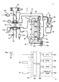
図1は、本発明の一実施形態が適用されたシステム1の全体構成を示す概略図である。図1を参照すると、本実施形態におけるシステム1は、エンジン2の制御パラメータの設定を行うためのベンチテストシステムであって、エンジン2と、燃料噴射装置3と、吸排気装置4と、本発明のパラメータ設定装置としての制御装置5と、を備えている。
<Overall system configuration>
FIG. 1 is a schematic diagram showing an overall configuration of a
本実施形態のエンジン2は、圧縮点火機関としてのディーゼルエンジンである。また、本実施形態においては、エンジン2には、複数(図1では4つ)の燃焼室21が、直列に配列形成されている。
The
<燃料噴射装置>
燃料噴射装置3は、燃焼室21と同数の複数のインジェクタ31を備えている。すなわち、各インジェクタ31は、各燃焼室21に対応するように配置されている。本実施形態のインジェクタ31は、周知のピエゾ式構成を有していて、燃焼室21内に燃料を直接的に噴射し得るように構成されている。
<Fuel injection device>
The
本実施形態の燃料噴射装置3は、周知のコモンレール式燃料噴射装置であって、各インジェクタ31は、コモンレール32と、燃料供給管33を介して接続されている。また、コモンレール32と燃料タンク34との間の燃料供給通路35には、燃料ポンプ36が介装されている。
The
<吸排気装置>
吸気マニホールド41は、各燃焼室21に空気(再循環された排出ガスを含む)を供給し得るように、エンジン2に装着されている。吸気マニホールド41は、エアクリーナ42と、吸気管43を介して接続されている。吸気管43には、スロットル44が介装されている。スロットル44は、ステッピングモータ等からなるスロットルアクチュエータ44aによって駆動されるようになっている。
<Intake and exhaust device>
The
排気マニホールド45は、各燃焼室21からの排出ガスを受容し得るように、エンジン2に装着されている。排気マニホールド45は、排気管46と接続されている。
The
吸気管43と排気管46との間には、ターボチャージャ47が介装されている。すなわち、吸気管43は、ターボチャージャ47のコンプレッサ47a側と接続されていて、排気管46は、ターボチャージャ47のタービン47b側と接続されている。
A
本実施形態におけるターボチャージャ47は、いわゆる可変ノズル方式のものである。すなわち、タービンロータ47b1と対向する位置には、可動式のベーンノズル47b2が設けられている。このベーンノズル47b2は、ベーンノズルアクチュエータ47b3によって駆動されるようになっている。
The
吸気マニホールド41と排気マニホールド45との間には、EGR(排気ガス再循環:Exhaust Gas Recirculation)装置48が介装されている。EGR装置48は、EGR通路48aと、EGR弁48bと、EGR弁アクチュエータ48cと、を備えている。
An EGR (Exhaust Gas Recirculation)
EGR通路48aは、EGRガス(再循環排出ガス)の通路であって、吸気マニホールド41と排気マニホールド45とを接続するように設けられている。このEGR通路48aには、EGR弁48bが介装されている。EGR弁48bは、EGR弁アクチュエータ48cによって駆動されることで、EGRガスの吸気マニホールド41への供給量(EGR率)を制御するようになっている。
The
<制御装置>
制御装置5は、エンジン2、燃料噴射装置3、及び吸排気装置4を備えた、システム1の動作を制御するものである。この制御装置5は、本発明のNOx−燃費ポテンシャル取得手段、NOx発生率目標値設定手段、制御パラメータ決定手段、初期設定手段、更新対象決定手段、及びNOx発生率目標値更新手段を構成する、電子制御ユニット(ECU)50を備えている。
<Control device>
The
ECU50は、CPU(マイクロプロセッサ)50aと、ROM(リードオンリーメモリ)50bと、RAM(ランダムアクセスメモリ)50cと、バックアップRAM50dと、インターフェース50eと、バス50fと、を備えている。CPU50a、ROM50b、RAM50c、バックアップRAM50d、及びインターフェース50eは、バス50fによって互いに接続されている。
The
CPU50aは、システム1における各部の動作を制御するためのルーチン(プログラム)を実行するように構成されている。ROM51bには、CPU50aが実行するルーチン、テーブル(ルックアップテーブル、マップ)、及びパラメータ等が予め格納されている。RAM50cは、CPU50aがルーチンを実行する際に、必要に応じてデータを一時的に格納し得るように構成されている。バックアップRAM50dは、電源が投入された状態でCPU50aがルーチンを実行する際にデータが格納されるとともに、この格納されたデータが電源遮断後も保持され得るように構成されている。
The
インターフェース50eは、後述する各種のセンサと電気的に接続されていて、これらのセンサからの検出信号をCPU50aに伝達し得るように構成されている。また、インターフェース50eは、インジェクタ31、燃料ポンプ36、スロットルアクチュエータ44a、ベーンノズルアクチュエータ47b3、EGR弁アクチュエータ48c、等の動作部と電気的に接続されていて、これらの動作部を動作させるための動作信号をCPU50aからこれらの動作部に伝達し得るように構成されている。すなわち、制御装置5は、インターフェース50eを介して上述の各センサからの検出信号を受け取り、当該検出信号に応じたCPU50aの演算結果に基づいて、各動作部に向けて動作信号を送出するように構成されている。
The
エアフローメータ51は、ターボチャージャ47のコンプレッサ47aよりも下流側にて、吸気管43に介装されている。このエアフローメータ51は、吸気管43内を流れる吸入空気の単位時間あたりの質量流量に応じた出力電圧を発生するように構成されている。
The
排出ガスセンサ52は、ターボチャージャ47のタービン47bよりも下流側にて、排気管46に介装されている。この排出ガスセンサ52は、排出ガス中の各成分(NOx等)の濃度に応じた出力電圧を発生するように構成されている。
The
コモンレール32には、レール圧センサ53が介装されている。このレール圧センサ53は、コモンレール32内の圧力に応じた出力電圧を発生するように構成されている。また、燃料供給通路35には、燃料流量センサ54が介装されている。この燃料流量センサ54は、燃料供給通路35を流れる燃料の流量に応じた出力電圧を発生するように構成されている。
A
クランク角度センサ55は、エンジン2のクランクシャフト(図示せず)が所定角度(例えば10°)回転する毎に幅狭のパルスを出力するとともに、当該クランクシャフトが360°回転する毎に幅広のパルスを出力するように構成されている。
The
アクセル開度センサ56は、運転者によって操作されるアクセルペダル56aの操作量(踏み込み量)に応じた出力電圧を発生するように構成されている。
The
また、インターフェース50eは、動力計57と電気的に接続されている。動力計57は、エンジン2のクランクシャフト(図示せず)と連結されていて、エンジン2の負荷を調整するようになっている。
The
<実施形態の構成による制御パラメータ設定動作の概要>
次に、本実施形態のシステム1による、エンジン2の制御パラメータの設定動作の概要について説明する。
<Outline of Control Parameter Setting Operation According to Configuration of Embodiment>
Next, the outline of the control parameter setting operation of the
本実施形態のエンジン2は、圧縮点火機関としてのディーゼルエンジンである。このエンジン2におけるNOx排出量低減手段として、本実施形態においては、EGRや、燃料噴射時期の遅角が用いられる。但し、これらにより、燃焼速度や等容度が低下することで、燃料消費率が悪化する。すなわち、NOx排出量と燃料消費率とは、トレードオフの関係となる。
The
ところで、NOx排出量等の排出ガス規制は、10・15モードやディーゼル13モード等の運転モード(車両走行モード)における総排出重量(あるいは単位距離走行あたりの排出重量)に基づいて行われる。但し、エミッション量や燃料消費率の特性は、回転領域及び負荷領域によって異なる。このため、各回転・負荷領域毎にNOx排出量等のエミッション量の個別目標値を割り付けつつ、その積算値が規制値内に収まり且つ燃費が所定範囲内となるように、制御パラメータ設定動作が行われる。 By the way, exhaust gas regulations such as NOx emission amount are performed based on the total discharge weight (or discharge weight per unit distance travel) in the operation mode (vehicle travel mode) such as the 10.15 mode and the diesel 13 mode. However, the characteristics of the emission amount and the fuel consumption rate vary depending on the rotation region and the load region. Therefore, the control parameter setting operation is performed so that the individual target value of the emission amount such as the NOx emission amount is assigned to each rotation / load region, and the integrated value is within the regulation value and the fuel consumption is within the predetermined range. Done.
<<NOx−燃費ポテンシャルの取得>>
図2は、回転・負荷領域毎のNOx発生率と燃料消費率との関係を概念的に示すグラフである(なお、図2においては、図示の便宜上、回転・負荷領域が4つに区分されているように示されている。しかしながら、かかる図示には、本発明をかかる内容に限定する意図はない。)。
<< NOx-Acquisition of fuel economy potential >>
FIG. 2 is a graph conceptually showing the relationship between the NOx generation rate and the fuel consumption rate for each rotation / load region (in FIG. 2, the rotation / load region is divided into four for convenience of illustration). However, such illustrations are not intended to limit the invention to such contents).
図2に示されているように、所定の運転モードにてNOx排出量規制及び目標燃費を満たすような、NOx排出量の個別目標値の割り付けパターンは、何通りも存在する(例えば、図中の丸記号の組み合わせ、三角記号の組み合わせ、×記号の組み合わせ、等。)。ここで、図中の丸記号の組み合わせが、NOx排出量及び燃費がともに最適になる組み合わせであるとすると、これを確実に探索することは極めて困難である。よって、従来の方法及び装置によれば、NOx排出量の個別目標値の割り付けパターンは、図中三角記号の組み合わせとなったり、×記号の組み合わせとなったりすることが通常である。 As shown in FIG. 2, there are various allocation patterns of individual target values of NOx emissions that satisfy the NOx emissions regulations and target fuel consumption in a predetermined operation mode (for example, in the figure). Circle symbol combinations, triangle symbol combinations, x symbol combinations, etc.). Here, if the combination of the circle symbols in the figure is a combination that optimizes both the NOx emission amount and the fuel consumption, it is extremely difficult to search for this reliably. Therefore, according to the conventional method and apparatus, the allocation pattern of the individual target value of the NOx emission amount is usually a combination of triangular symbols or a combination of X symbols in the figure.
これに対し、本実施形態においては、まず、NOx−燃費ポテンシャルが、複数の回転・負荷領域について取得される。このNOx−燃費ポテンシャルは、燃料消費率及びNOx発生率を座標軸とする平面上における、NOx発生率の最低値の、燃料消費率に対する変化軌跡として規定される(図中の曲線参照)。なお、図中の各点は、各回転・負荷領域にて、制御パラメータ(EGR弁48bやベーンノズル47b2の開度等)の多数の組み合わせを用いてエンジン2を運転した場合の、実現可能な燃料消費率及びNOx発生率を示すものとする。
On the other hand, in the present embodiment, first, NOx-fuel economy potential is acquired for a plurality of rotation / load regions. This NOx-fuel efficiency potential is defined as a change locus of the minimum value of the NOx generation rate with respect to the fuel consumption rate on a plane having the fuel consumption rate and the NOx generation rate as coordinate axes (see the curve in the figure). Each point in the figure represents a fuel that can be realized when the
本実施形態においては、NOx−燃費ポテンシャルは、以下のようにして取得される。 In the present embodiment, the NOx-fuel efficiency potential is acquired as follows.
NOx発生量を低減する要因として最も効果(感度)が大きいのはEGRであり、その次が燃料噴射時期の遅角である。その反面、燃費の悪化については、逆に、燃料噴射時期の遅角の影響の方がEGRの影響よりも大きい。また、EGRに対する影響が最も大きいのはEGR弁48bの開度であり、次がベーンノズル47b2の開度であり、その次がスロットル44の開度である。
EGR has the greatest effect (sensitivity) as a factor for reducing the amount of NOx generated, and the next is the delay of the fuel injection timing. On the other hand, regarding the deterioration of fuel consumption, the influence of retarding the fuel injection timing is larger than that of EGR. The greatest influence on EGR is the opening of the
そこで、本実施形態のNOx−燃費ポテンシャルの取得に際しては、NOx発生量が多く燃費が極めて良好な初期状態が設定された後、まずEGRを増量する方向に制御パラメータが操作され、次に燃料噴射時期が操作される。このとき、EGR増量操作の優先順位は、(1)EGR弁48b、(2)ベーンノズル47b2、(3)スロットル44、とする。但し、空気過剰率λがスモーク限界x未満となった場合には、新気を導入する必要性から、EGR弁48bとベーンノズル47b2との優先順位が変更される。
Therefore, when obtaining the NOx-fuel efficiency potential of the present embodiment, after setting an initial state in which the amount of NOx generated is large and the fuel efficiency is extremely good, the control parameter is first operated in the direction of increasing the EGR, and then the fuel injection is performed. Time is manipulated. At this time, the priority order of the EGR increase operation is (1)
このような手順によれば、NOx−燃費ポテンシャルの取得処理が、自動的且つより効率的に行われ得る。 According to such a procedure, the NOx-fuel efficiency potential acquisition process can be performed automatically and more efficiently.
<<NOx−燃費ポテンシャルを用いたNOx発生率個別目標値の決定>>
上述のようにして取得されたNOx−燃費ポテンシャルを用いて、NOx排出量と燃費との背反がより少なくなるような制御パラメータの設定が行われる。
<< NOx-Determination of NOx generation rate individual target value using fuel efficiency potential >>
Using the NOx-fuel efficiency potential acquired as described above, control parameters are set such that the contradiction between the NOx emission amount and the fuel efficiency is reduced.
すなわち、図2に示されているように、各回転・負荷領域におけるNOx−燃費ポテンシャルは、NOx発生率を一定にした場合の最低燃料消費率、あるいは、燃料消費率を一定にした場合の最低NOx発生率を示す曲線となる。よって、各回転・負荷領域にて、NOx発生量目標値と燃料消費率目標値とを、NOx−燃費ポテンシャル上の点となるように割り付けることで、NOx排出量と燃費との背反がより少なくなるような制御パラメータ設定結果が得られる。 That is, as shown in FIG. 2, the NOx-fuel efficiency potential in each rotation / load region is the minimum fuel consumption rate when the NOx generation rate is constant, or the minimum when the fuel consumption rate is constant. It becomes a curve showing the NOx generation rate. Therefore, by allocating the NOx generation amount target value and the fuel consumption rate target value so as to be points on the NOx-fuel efficiency potential in each rotation / load region, there is less contradiction between the NOx emission amount and the fuel efficiency. A control parameter setting result is obtained.
具体的には、まず、各回転・負荷領域にて、NOx発生率が最も高くなる側(図2における右側:このときトレードオフとして燃費が最も良くなる)のNOx−燃費ポテンシャル上の点が、初期値として設定される。 Specifically, first, in each rotation / load region, the point on the NOx-fuel consumption potential on the side where the NOx generation rate is the highest (right side in FIG. 2: the fuel consumption becomes the best as a trade-off at this time) Set as initial value.
次に、各点における勾配(の絶対値)が最小、すなわち、NOx発生率を現在の目標値から所定量低減させたときの燃料消費率の増加割合が最小となるような、NOx−燃費ポテンシャルが決定(検索)される。 Next, the NOx-fuel consumption potential is such that the gradient at each point (the absolute value thereof) is minimum, that is, the increase rate of the fuel consumption rate is minimized when the NOx generation rate is reduced by a predetermined amount from the current target value. Is determined (searched).
続いて、決定(検索)されたNOx−燃費ポテンシャルに対応する回転・負荷領域にて、NOx発生率が現在の目標値から低減するように(図2における左側に)、NOx−燃費ポテンシャル上の点が所定量移動させられる。 Subsequently, in the rotation / load region corresponding to the determined (searched) NOx-fuel efficiency potential, the NOx occurrence rate is reduced from the current target value (on the left side in FIG. 2) on the NOx-fuel efficiency potential. The point is moved a predetermined amount.
かかる動作が、NOx排出量が規制値を満たすまで繰り返される。これにより、NOx排出量及び燃費がともに最適になるように、各回転・負荷領域におけるNOx発生率個別目標値が割り付けられる。そして、これに基づいて、NOx排出量及び燃費がともに最適になるような制御パラメータ設定結果が、確実且つ簡易に得られる。 Such an operation is repeated until the NOx emission amount satisfies the regulation value. Thereby, the NOx generation rate individual target value in each rotation / load region is assigned so that both the NOx emission amount and the fuel consumption are optimized. Based on this, a control parameter setting result that optimizes both the NOx emission amount and the fuel consumption can be obtained reliably and easily.
<実施形態の構成による制御パラメータ設定動作の具体例>
次に、本実施形態のシステム1による、エンジン2の制御パラメータ設定動作の一つの具体例について、フローチャートを用いて説明する。なお、各図のフローチャートにおいては、「ステップ」は“S”と略記されている。
<Specific Example of Control Parameter Setting Operation According to Configuration of Embodiment>
Next, one specific example of the control parameter setting operation of the
<<NOx−燃費ポテンシャル取得>>
図3ないし図6は、図1に示されている本実施形態の制御装置5による、NOx−燃費ポテンシャル取得ルーチンの一具体例を示すフローチャートである。なお、本実施形態においては、ECU50(CPU50a)によるルーチン300の実行によって、本発明のNOx−燃費ポテンシャル取得手段が実現されている。
<< NOx-Fuel consumption potential acquisition >>
3 to 6 are flowcharts showing a specific example of the NOx-fuel efficiency potential acquisition routine by the
このルーチン300は、ある1つの回転・負荷領域に対応するNOx−燃費ポテンシャル取得に対して、1通りずつ実行されるものとする。すなわち、回転・負荷領域が9つに分割される場合、各回転・負荷領域に対応して、ルーチン300が計9回実行される。これにより、各回転・負荷領域に対応して、9つのNOx−燃費ポテンシャルが取得される。このとき、ルーチン300の実行によるNOx−燃費ポテンシャル取得中は、エンジン回転数及び負荷が一定となるように、エンジン2の運転が制御されているものとする。
This routine 300 is executed one by one for NOx-fuel efficiency potential acquisition corresponding to a certain rotation / load region. That is, when the rotation / load region is divided into nine, the routine 300 is executed a total of nine times corresponding to each rotation / load region. Accordingly, nine NOx-fuel economy potentials are acquired corresponding to each rotation / load region. At this time, it is assumed that the operation of the
また、NOx−燃費ポテンシャルの取得動作における初期条件は、以下の通りである。
EGR弁48b:全閉
ベーンノズル47b2:ターボチャージャ47の諸元及び回転・負荷条件によって定まる燃費最適開度
スロットル44:全開
燃料噴射時期:MBT(最も発生トルクが大となる噴射時期)
The initial conditions in the NOx-fuel efficiency potential acquisition operation are as follows.
ルーチン300が起動されると、まず、ステップ310にて、空気過剰率λが所定のスモーク限界xよりも大きいか否かが判定される。ここで、空気過剰率λは、エアフローメータ51の出力と、EGR弁48bの開度と、燃料噴射量(周知の空燃比フィードバック制御によりECU50によって算出される指令燃料噴射時間)と、から求められる。
When the routine 300 is started, first, at step 310, it is determined whether or not the excess air ratio λ is larger than a predetermined smoke limit x. Here, the excess air ratio λ is obtained from the output of the
空気過剰率λがスモーク限界x以下である場合(ステップ310=No)、ステップ320以降の処理(EGR弁48bの操作)がスキップされ、処理が図4のフロー(ベーンノズル47b2の操作)に進行する(図中(2)参照:上述の優先順位変更)。一方、空気過剰率λがスモーク限界xよりも大きい場合(ステップ310=Yes)、処理がステップ320以降に進行する。
When the excess air ratio λ is equal to or less than the smoke limit x (step 310 = No), the processing after step 320 (operation of the
ステップ320においては、EGR弁48bが全開であるか否かが判定される。上述の初期条件においては、EGR弁48bは全閉であるので(ステップ320=No)、処理がステップ330以降に進行する。なお、ステップ320の判定が「Yes」である場合、ステップ330以降の処理がスキップされ、処理が図4のフローに進行する(図中(2)参照)。
In step 320, it is determined whether or not the
ステップ330においては、EGR弁48bが1ステップ分だけ開かれる(このときベーンノズル47b2の開度は上述の燃費最適開度とされる)。なお、ここでいう「1ステップ分」は、EGR弁48bの開度を調整(変更)する場合のEGR弁アクチュエータ48cの駆動量の最小単位をいうものとする。次に、処理がステップ340に進行し、空気過剰率λがスモーク限界xよりも大きいか否かが再度判定される。
In step 330, the
空気過剰率λがスモーク限界xよりも大きい場合(ステップ340=Yes)、処理がステップ350に進行して、燃料噴射時期がMBTに設定される。続いて、ステップ360にて、NOx発生率及び燃料消費率が計測され、処理が再度ルーチン300の最初のステップに戻る。なお、NOx発生率は、排出ガスセンサ52の出力に基づいて取得される。また、燃料消費率は、レール圧センサ53及び燃料流量センサ54の出力と、インジェクタ31への通電時間と、に基づいて取得される。
When the excess air ratio λ is larger than the smoke limit x (step 340 = Yes), the process proceeds to step 350, and the fuel injection timing is set to MBT. Subsequently, at
空気過剰率λがスモーク限界x以下である場合(ステップ340=No)、処理がステップ370に進行し、直前の操作が戻される。すなわち、EGR弁48bが1ステップ分だけ閉じられる。その後、ステップ310の判定が「No」の場合及びステップ320の判定が「Yes」の場合と同様に処理が進行する(図中(2)参照)。
When the excess air ratio λ is equal to or less than the smoke limit x (step 340 = No), the process proceeds to step 370, and the immediately preceding operation is returned. That is, the
処理が図4のフローに進行した場合(図中上方の(2)参照)、ステップ410にて、ベーンノズル47b2が全開であるか否かが判定される。上述の初期条件においては、ベーンノズル47b2の開度は上述の燃費最適開度であるので(ステップ410=No)、処理がステップ420以降に進行する。なお、ステップ410の判定が「Yes」である場合、ステップ420以降の処理がスキップされ、処理が図5のフロー(スロットル44の操作)に進行する(図中(3)参照)。
When the process proceeds to the flow of FIG. 4 (see (2) in the upper part of the figure), in step 410, it is determined whether or not the vane nozzle 47b2 is fully opened. Under the above-mentioned initial conditions, the opening degree of the vane nozzle 47b2 is the above-described optimum fuel economy opening degree (step 410 = No), and thus the process proceeds to step 420 and thereafter. When the determination in step 410 is “Yes”, the processing after
ステップ420においては、ベーンノズル47b2が1ステップ分だけ閉じられる。なお、ここでいう「1ステップ分」は、ベーンノズル47b2の開度を調整(変更)する場合のベーンノズルアクチュエータ47b3の駆動量の最小単位をいうものとする。
In
次に、処理がステップ430に進行し、空気過剰率λがスモーク限界xよりも大きいか否かが再度判定される。空気過剰率λがスモーク限界xよりも大きい場合(ステップ430=Yes)、処理がステップ440に進行して、燃料噴射時期がMBTに設定される。続いて、ステップ450にて、NOx発生率及び燃料消費率が計測され、処理が再度ルーチン300の最初のステップに戻る。
Next, the process proceeds to step 430, and it is determined again whether or not the excess air ratio λ is larger than the smoke limit x. When the excess air ratio λ is larger than the smoke limit x (step 430 = Yes), the process proceeds to step 440, and the fuel injection timing is set to MBT. Subsequently, at
空気過剰率λがスモーク限界x以下である場合(ステップ430=No)、処理がステップ460に進行し、空気過剰率λがスモーク限界xと等しくなるように、EGR弁48bの開度が設定される。次に、処理がステップ470に進行し、前回計測時よりも酸素濃度が下がっているか否かが、排出ガスセンサ52の出力に基づいて判定される。
When the excess air ratio λ is equal to or less than the smoke limit x (step 430 = No), the process proceeds to step 460, and the opening degree of the
前回計測時よりも酸素濃度が下がっている場合(ステップ470=Yes)、処理がステップ440及び450に進行し、NOx発生率及び燃料消費率が計測され、処理が再度ルーチン300の最初のステップに戻る。前回計測時よりも酸素濃度が下がっていない場合(ステップ470=No)、処理がステップ480に進行して燃料噴射時期がMBTに設定され、処理がステップ410に戻る。
If the oxygen concentration is lower than the previous measurement (step 470 = Yes), the process proceeds to
処理が図5のフローに進行した場合(図中(3)参照)、ステップ510にて、スロットル44が全閉であるか否かが判定される。上述の初期条件においては、スロットル44は全開であるので(ステップ510=No)、処理がステップ520以降に進行する。なお、ステップ510の判定が「Yes」である場合、スロットルアクチュエータ44a等のスロットル制御系の異常により誤ってスロットル44が全閉になったことが推定される。よって、この場合、ステップ520以降の処理がスキップされて異常処理が行われ、本ルーチンが終了する。
When the process proceeds to the flow of FIG. 5 (see (3) in the figure), it is determined in step 510 whether or not the
ステップ520においては、スロットル44が1ステップ分だけ閉じられる。次に、処理がステップ530に進行し、空気過剰率λがスモーク限界xよりも大きいか否かが再度判定される。
In step 520, the
空気過剰率λがスモーク限界xよりも大きい場合(ステップ530=Yes)、処理がステップ540及び550に進行して、燃料噴射時期がMBTに設定された後にNOx発生率及び燃料消費率が計測され、処理が再度ルーチン300の最初のステップに戻る。 When the excess air ratio λ is larger than the smoke limit x (step 530 = Yes), the process proceeds to steps 540 and 550, and the NOx generation rate and the fuel consumption rate are measured after the fuel injection timing is set to MBT. The process returns to the first step of the routine 300 again.
空気過剰率λがスモーク限界x以下である場合(ステップ530=No)、処理がステップ560に進行し、直前の操作が戻される。すなわち、スロットル44が1ステップ分だけ開かれる。その後、処理が図6のフロー(燃料噴射時期操作)に進行する(図中(4)参照)。
When the excess air ratio λ is equal to or less than the smoke limit x (step 530 = No), the process proceeds to step 560, and the immediately preceding operation is returned. That is, the
処理が図6のフローに進行した場合(図中(4)参照)、ステップ610にて、失火余裕度yが、「所定値y0+1ステップ分」未満であるか否かが判定される。ここで、失火余裕度とは、今回の燃料噴射(主噴射)時期の、失火限界時期(失火が発生しない範囲内で最も遅角側の主噴射時期)からの進角側への偏差をいうものとする。また、「1ステップ分」は、燃料噴射時期を調整(変更)する場合の最小単位をいうものとする。
When the process proceeds to the flow of FIG. 6 (see (4) in the figure), in
失火余裕度が充分ある場合、すなわち、yが「所定値y0+1ステップ分」以上である場合(ステップ610=No)、処理がステップ620に進行し、燃料噴射時期が1ステップ分遅角され、その後ステップ630にてNOx発生率及び燃料消費率が計測され、処理が再度ルーチン300の最初のステップに戻る。一方、yが「所定値y0+1ステップ分」未満である場合(ステップ610=Yes)、本ルーチンが終了する。このとき、ある回転・負荷領域(回転・負荷条件)におけるNOx−燃費ポテンシャルの取得処理が終了する。 If the misfire margin is sufficient, that is, if y is greater than or equal to “predetermined value y0 + 1 step” (step 610 = No), the process proceeds to step 620 and the fuel injection timing is delayed by one step, and thereafter In step 630, the NOx generation rate and the fuel consumption rate are measured, and the process returns to the first step of the routine 300 again. On the other hand, when y is less than “predetermined value y0 + 1 step” (step 610 = Yes), this routine ends. At this time, the NOx-fuel efficiency potential acquisition process in a certain rotation / load region (rotation / load condition) ends.
<<NOx−燃費ポテンシャルを用いたNOx発生率個別目標値の決定>>
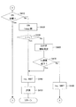
図7は、図1に示されている本実施形態の制御装置5による、NOx発生率個別目標値の決定(割り付け)ルーチンの一具体例を示すフローチャートである。
<< NOx-Determination of NOx generation rate individual target value using fuel efficiency potential >>
FIG. 7 is a flowchart showing a specific example of a routine for determining (allocating) the NOx generation rate individual target value by the
なお、以下の記述における各記号の意義は、下記の通りである。
dk:k番目の回転・負荷領域の運転モード中頻度[kWh]
=k番目の回転・負荷領域の、所定の運転モード中の時間[h]
×エンジン回転数及び負荷から求められる仕事[kW]
xk:k番目の回転・負荷領域のNOx発生率の個別目標値[g/kWh]
QNOx_t:モードトータルNOx量(所定の運転モードにおけるNOx発生総量)
=Σdkxk
A:所定の運転モードにおけるNOx発生量の総量目標値[g]
fk:k番目の回転・負荷領域のNOx−燃費ポテンシャル[g/kWh]
X=(x1,x2,・・・,xn)
g(X):モードトータル燃費ポテンシャル関数[g]
=Σdkfk(xk)
In addition, the meaning of each symbol in the following description is as follows.
d k : Frequency during operation mode of the k-th rotation / load region [kWh]
= Time during the predetermined operation mode in the k-th rotation / load region [h]
× Work required from engine speed and load [kW]
x k : Individual target value [g / kWh] of the NOx generation rate in the k-th rotation / load region
QNOx_t: mode total NOx amount (total NOx generation amount in a predetermined operation mode)
= Σd k x k
A: Total amount target value of NOx generation amount in a predetermined operation mode [g]
f k : NOx-fuel efficiency potential [g / kWh] in the k-th rotation / load region
X = (x 1 , x 2 ,..., X n )
g (X): Mode total fuel consumption potential function [g]
= Σd k f k (x k )
本ルーチン700が起動されると、まず、ステップ710にて、ベクトルXの大きさが最大となるように、x1,x2,・・・,xnの初期値が設定される。すなわち、各回転・負荷領域における、NOx発生率が最も高くなる側(図2における右側:このときトレードオフとして燃費が最も良くなる)のNOx−燃費ポテンシャル上の点が、初期状態として設定される。 When the routine 700 is started, first, in step 710, initial values of x 1 , x 2 ,..., X n are set so that the size of the vector X is maximized. That is, the point on the NOx-fuel consumption potential on the side where the NOx generation rate is the highest in each rotation / load region (the right side in FIG. 2: the fuel consumption becomes the best as a trade-off at this time) is set as the initial state. .
次に、ステップ720にて、モードトータルNOx量(QNOx_t)が所定値Aより多いか否かが判定される。本ルーチンの起動後初回の処理においては、ステップ720の判定は「Yes」となるので、処理がステップ730に進行し、x1,x2,・・・,xnのうちのNOx−燃費ポテンシャルの勾配(接線の傾き)の絶対値が最小の点、すなわち、NOx発生率xkを所定量低減させたときの燃料消費率の増加割合が最小となるようなNOx−燃費ポテンシャルfkが、探索(決定)される。 Next, at step 720, it is determined whether or not the mode total NOx amount (QNOx_t) is greater than a predetermined value A. In the processing start after the first routine, the determination of step 720 is "Yes", NOx-fuel potential of the processing proceeds to step 730, x 1, x 2, ···, x n gradient (tangent slope) of the absolute value of the minimum point, i.e., the NOx- fuel potential f k as the increase rate of the fuel consumption rate becomes the minimum when the NOx generation rate x k is reduced a predetermined amount, Searched (determined).
続いて、ステップ740にて、探索されたk番目の回転・負荷領域におけるNOx発生率の個別目標値xkが、所定量増加させられる。その後、処理がステップ720に戻る。 Subsequently, at step 740, the individual target value x k of the NOx generation rate in the searched k-th rotation and the load regions can be increased a predetermined amount. Thereafter, the process returns to step 720.
上述のステップ720ないし740の処理が繰り返されることで、各回転・負荷領域におけるNOx発生率の個別目標値xkと燃料消費率との組み合わせがNOx−燃費ポテンシャル上の点となるという条件下で、燃費が可及的に悪化しないようにしつつモードトータルNOx量が徐々に減少させられる。 Step 720 without the above that the process of 740 is repeated, under the condition that the combination of the individual target value x k and the fuel consumption rate of NOx generation rate of each rotation and load region is a point on the NOx- fuel potential The mode total NOx amount is gradually decreased while preventing the fuel consumption from being deteriorated as much as possible.
その後、ステップ720の判定結果が「No」に転じた時点で、処理がステップ750に進行する。ステップ750においては、決定された各回転・負荷領域におけるNOx−燃費ポテンシャル上の点(NOx発生率の個別目標値xkの割り付け)に基づいて、各回転・負荷領域における制御パラメータ(EGR弁開度、VN開度、スロットル開度、燃料噴射時期、等)が設定される。そして、本ルーチンの処理が終了する。 Thereafter, when the determination result at step 720 turns to “No”, the process proceeds to step 750. In step 750, based on the point on the NOx- fuel potential in each rotation-load region determined (assignment of individual target value x k of the NOx generation rate) control parameters in each rotation-load region (EGR valve opening Degree, VN opening, throttle opening, fuel injection timing, etc.) are set. Then, the processing of this routine ends.
かかるルーチン700の処理によれば、所定の運転モードにおけるNOx発生量の総量目標値Aを満たしつつ、燃費が最適となるように、各回転・負荷領域におけるNOx−燃費ポテンシャル上の点の決定すなわちNOx発生率の個別目標値xkの割り付けが行われる。 According to the processing of the routine 700, determination of a point on the NOx-fuel consumption potential in each rotation / load region so as to optimize the fuel consumption while satisfying the total NOx generation target value A in the predetermined operation mode, that is, assignment of the individual target value x k of the NOx generation rate is performed.
そして、このようにして決定されたNOx−燃費ポテンシャル上の点に基づいて、各回転・負荷領域における制御パラメータが設定される。したがって、本ルーチン700の処理によれば、NOx排出量及び燃費がともに最適になるような、制御パラメータ設定結果が、確実且つ簡易に得られる。 Then, based on the point on the NOx-fuel consumption potential determined in this way, control parameters in each rotation / load region are set. Therefore, according to the processing of this routine 700, a control parameter setting result that optimizes both the NOx emission amount and the fuel consumption can be obtained reliably and easily.
なお、本実施形態においては、ECU50(CPU50a)によるルーチン700の実行によって、本発明のNOx発生率目標値設定手段が実現されているものとする。同様に、ステップ710の処理によって、本発明の初期設定手段が実現されている。また、ステップ730の処理によって、本発明の更新対象決定手段が実現されている。また、ステップ740の処理によって、本発明のNOx発生率目標値更新手段が実現されている。また、ステップ750の処理によって、本発明の制御パラメータ決定手段が実現されている。
In the present embodiment, it is assumed that the NOx generation rate target value setting means of the present invention is realized by execution of the routine 700 by the ECU 50 (
<変形例の例示列挙>
なお、上述の実施形態は、上述した通り、出願人が取り敢えず本願の出願時点において最良であると考えた本発明の代表的な実施形態を単に例示したものにすぎない。よって、本発明はもとより上述の実施形態に何ら限定されるものではない。
<List of examples of modification>
Note that, as described above, the above-described embodiments are merely examples of typical embodiments of the present invention that the applicant has considered to be the best at the time of filing of the present application. Therefore, the present invention is not limited to the above-described embodiment.
したがって、本発明の本質的部分を変更しない範囲内において、上述の実施形態に対して種々の変形が施され得ることは、当然である。 Therefore, it goes without saying that various modifications can be made to the above-described embodiment within the scope not changing the essential part of the present invention.
以下、代表的な変形例について、幾つか例示する。もっとも、言うまでもなく、変形例とて、以下に列挙されたもの限定されるものではない。また、複数の変形例が、技術的に矛盾しない範囲内において、適宜、複合的に適用され得る。 Hereinafter, some typical modifications will be exemplified. However, it goes without saying that the modifications are not limited to those listed below. In addition, a plurality of modified examples can be applied in a composite manner as appropriate within a technically consistent range.
本発明(特に、本発明の課題を解決するための手段を構成する各構成要素における、作用的・機能的に表現されているもの)は、上述の実施形態や、下記変形例の記載に基づいて限定解釈されてはならない。このような限定解釈は、(先願主義の下で出願を急ぐ)出願人の利益を不当に害する反面、模倣者を不当に利するものであって、許されない。 The present invention (especially those expressed functionally and functionally in the constituent elements constituting the means for solving the problems of the present invention) is based on the above-described embodiment and the description of the following modifications. Should not be interpreted as limited. Such a limited interpretation is unacceptable and improper for imitators, while improperly harming the applicant's interests (rushing to file under a prior application principle).
(A)本発明は、上記の実施形態にて開示された具体的な装置構成に限定されない。 (A) The present invention is not limited to the specific apparatus configuration disclosed in the above embodiment.
例えば、本システム1は、エンジン2を搭載した機械(車両等)であってもよい。すなわち、本発明の制御パラメータ設定作業は、ベンチテストシステムにおいても行われ得るし、機械搭載(車載)状態でも行われ得る。また、エンジン開発時(適合作業時)にも行われ得るし、生産エンジンや生産車両の出荷前テストや出荷後点検の際にも行われ得る。
For example, the
また、気筒数や気筒配列方式についても、特段の限定はない。 Further, there is no particular limitation on the number of cylinders and the cylinder arrangement method.
さらに、本発明は、ターボチャージャ47が可変式でなくても、あるいはターボチャージャ47がなくても、適用可能である。同様に、本発明は、スロットル44がなくても適用可能である。
Furthermore, the present invention can be applied even if the
(B)本発明は、上記の実施形態にて開示された具体的な処理に限定されない。 (B) The present invention is not limited to the specific processing disclosed in the above embodiment.
例えば、NOx−燃費ポテンシャルの取得は、上記の実施形態のような制御装置5による自動取得(図3ないし図6のフローチャート参照)ではなく、実験計画法等を用いた手動取得でもよい。
For example, the NOx-fuel consumption potential may be acquired not by automatic acquisition by the
また、x1,x2,・・・,xnの初期値は、ベクトルXの大きさが最大とならなくても、モードトータルの燃料消費量が所定の燃費目標値未満になるように設定され得る。 In addition, the initial values of x 1 , x 2 ,..., X n are set so that the total mode fuel consumption is less than a predetermined fuel consumption target value even if the magnitude of the vector X is not maximized. Can be done.
(C)その他、特段に言及されていない変形例についても、本発明の本質的部分を変更しない範囲内において、本発明の範囲内に含まれることは当然である。 (C) Other modifications not specifically mentioned are naturally included in the scope of the present invention as long as they do not change the essential part of the present invention.
また、本発明の課題を解決するための手段を構成する各要素における、作用・機能的に表現されている要素は、上述の実施形態や変形例にて開示されている具体的構造の他、当該作用・機能を実現可能ないかなる構造をも含む。さらに、本明細書にて引用した各公報の内容(明細書及び図面を含む)は、本明細書の一部を構成するものとして援用され得る。 In addition, in each element constituting the means for solving the problems of the present invention, elements expressed functionally and functionally include the specific structures disclosed in the above-described embodiments and modifications, It includes any structure that can realize this action / function. Furthermore, the contents (including the specification and drawings) of each publication cited in the present specification may be incorporated as part of the specification.
1…システム 2…エンジン 21…燃焼室
3…燃料噴射装置 31…インジェクタ 32…コモンレール
4…吸排気装置 44…スロットル 44a…スロットルアクチュエータ
47…ターボチャージャ 47b2…ベーンノズル 47b3…VNアクチュエータ
48…EGR装置 48b…EGR弁 48c…EGR弁アクチュエータ
5…制御装置 50…ECU 50a…CPU
51…エアフローメータ 52…排出ガスセンサ 53…レール圧センサ
54…燃料流量センサ 55…クランク角度センサ 57…動力計
DESCRIPTION OF
DESCRIPTION OF
Claims (2)
単位時間単位出力あたりのNOx発生量であるNOx発生率及び燃料消費率を座標軸とする平面上における前記燃料消費率の最低値の前記NOx発生率に対する変化軌跡として規定されるNOx−燃費ポテンシャルを、機関回転数及び機関負荷についての複数の条件毎に取得する、NOx−燃費ポテンシャル取得手段と、
前記内燃機関の排出ガス規制における排出ガス試験測定用運転モードにしたがって前記内燃機関を運転させたときのNOx発生総量を所定の総量目標値以下にしつつ燃料消費量を最小にするように、複数の前記条件の各々に対応する前記NOx−燃費ポテンシャル上の点を決定することで、複数の前記条件の各々における前記NOx発生率の個別目標値を設定する、NOx発生率目標値設定手段と、
前記NOx発生率目標値設定手段によって決定された複数の前記点に基づいて、複数の前記条件の各々における前記制御パラメータを決定する、制御パラメータ決定手段と、
を備えたことを特徴とする、内燃機関の制御パラメータの設定装置。 A control parameter setting device for an internal combustion engine,
NOx-fuel efficiency potential defined as a change locus with respect to the NOx generation rate of the minimum value of the fuel consumption rate on a plane having the NOx generation rate and the fuel consumption rate as coordinate axes as the NOx generation amount per unit time unit output, NOx-fuel efficiency potential acquisition means for acquiring a plurality of conditions for the engine speed and engine load;
A plurality of NOx generation amounts when the internal combustion engine is operated according to the exhaust gas test measurement operation mode in the exhaust gas regulations of the internal combustion engine are set to be equal to or less than a predetermined total amount target value while minimizing fuel consumption. NOx generation rate target value setting means for setting an individual target value of the NOx generation rate in each of the plurality of conditions by determining a point on the NOx-fuel economy potential corresponding to each of the conditions;
Control parameter determining means for determining the control parameter in each of the plurality of conditions based on the plurality of points determined by the NOx occurrence rate target value setting means;
A control parameter setting device for an internal combustion engine, comprising:
前記NOx発生率目標値設定手段は、
複数の前記条件の各々に対応する前記NOx−燃費ポテンシャル上の前記点の初期状態を設定する、初期設定手段と、
複数の前記条件の各々に対応する前記NOx−燃費ポテンシャルのうちの、前記点における前記NOx発生率を低減させたときの前記燃料消費率の増加割合が最小のものを決定する、更新対象決定手段と、
前記更新対象決定手段によって決定された前記NOx−燃費ポテンシャル上の前記点を、前記NOx発生率が低減する方向に移動させることで、当該NOx−燃費ポテンシャルに対応する前記条件における前記NOx発生率の前記個別目標値を更新する、NOx発生率目標値更新手段と、
を備えたことを特徴とする、内燃機関の制御パラメータの設定装置。 A control parameter setting device for an internal combustion engine according to claim 1,
The NOx occurrence rate target value setting means includes:
Initial setting means for setting an initial state of the point on the NOx-fuel economy potential corresponding to each of a plurality of the conditions;
Update target determination means for determining the NOx-fuel economy potential corresponding to each of the plurality of conditions that has the smallest increase rate of the fuel consumption rate when the NOx generation rate at the point is reduced When,
By moving the point on the NOx-fuel consumption potential determined by the update target determining means in a direction in which the NOx generation rate is reduced, the NOx generation rate in the condition corresponding to the NOx-fuel consumption potential is increased. NOx occurrence rate target value updating means for updating the individual target value;
A control parameter setting device for an internal combustion engine, comprising:
Priority Applications (1)
| Application Number | Priority Date | Filing Date | Title |
|---|---|---|---|
| JP2008317910A JP5115464B2 (en) | 2008-12-15 | 2008-12-15 | Device for setting control parameters of internal combustion engine |
Applications Claiming Priority (1)
| Application Number | Priority Date | Filing Date | Title |
|---|---|---|---|
| JP2008317910A JP5115464B2 (en) | 2008-12-15 | 2008-12-15 | Device for setting control parameters of internal combustion engine |
Publications (2)
| Publication Number | Publication Date |
|---|---|
| JP2010138864A JP2010138864A (en) | 2010-06-24 |
| JP5115464B2 true JP5115464B2 (en) | 2013-01-09 |
Family
ID=42349192
Family Applications (1)
| Application Number | Title | Priority Date | Filing Date |
|---|---|---|---|
| JP2008317910A Expired - Fee Related JP5115464B2 (en) | 2008-12-15 | 2008-12-15 | Device for setting control parameters of internal combustion engine |
Country Status (1)
| Country | Link |
|---|---|
| JP (1) | JP5115464B2 (en) |
Families Citing this family (2)
| Publication number | Priority date | Publication date | Assignee | Title |
|---|---|---|---|---|
| JP6755167B2 (en) * | 2016-12-05 | 2020-09-16 | いすゞ自動車株式会社 | Control device |
| JP7364000B1 (en) | 2022-09-12 | 2023-10-18 | いすゞ自動車株式会社 | NOx generation amount control device |
Family Cites Families (13)
| Publication number | Priority date | Publication date | Assignee | Title |
|---|---|---|---|---|
| DE19747231A1 (en) * | 1997-10-25 | 1999-04-29 | Bosch Gmbh Robert | Method for injecting fuel into the combustion chambers of an air-compressing, self-igniting internal combustion engine |
| JP2002206456A (en) * | 2001-01-12 | 2002-07-26 | Toyota Motor Corp | Method and system for adapting engine control parameter |
| JP3551160B2 (en) * | 2001-03-30 | 2004-08-04 | トヨタ自動車株式会社 | Vehicle control device |
| JP3959980B2 (en) * | 2001-04-26 | 2007-08-15 | 三菱ふそうトラック・バス株式会社 | Data analysis method and apparatus based on experiment design method, data analysis program based on experiment design method, and computer-readable recording medium recording the program |
| JP4706134B2 (en) * | 2001-06-15 | 2011-06-22 | トヨタ自動車株式会社 | Control device for internal combustion engine |
| JP3951967B2 (en) * | 2002-08-01 | 2007-08-01 | トヨタ自動車株式会社 | Automatic adapting device |
| JP2006118515A (en) * | 2002-08-01 | 2006-05-11 | Toyota Motor Corp | Automatic compliance device |
| JP4182980B2 (en) * | 2002-08-01 | 2008-11-19 | トヨタ自動車株式会社 | Automatic adaptation device for internal combustion engine |
| JP4305257B2 (en) * | 2004-04-14 | 2009-07-29 | トヨタ自動車株式会社 | Automatic adapting device |
| JP4362572B2 (en) * | 2005-04-06 | 2009-11-11 | 独立行政法人 宇宙航空研究開発機構 | Problem processing method and apparatus for solving robust optimization problem |
| JP4419918B2 (en) * | 2005-06-21 | 2010-02-24 | トヨタ自動車株式会社 | Internal combustion engine adaptation method |
| US7296555B2 (en) * | 2005-08-25 | 2007-11-20 | General Electric Company | System and method for operating a turbo-charged engine |
| JP4928484B2 (en) * | 2008-02-29 | 2012-05-09 | 株式会社小野測器 | Method, computer and program for calculating engine design variables |
-
2008
- 2008-12-15 JP JP2008317910A patent/JP5115464B2/en not_active Expired - Fee Related
Also Published As
| Publication number | Publication date |
|---|---|
| JP2010138864A (en) | 2010-06-24 |
Similar Documents
| Publication | Publication Date | Title |
|---|---|---|
| US7150264B2 (en) | Control device for internal combustion engine | |
| US7236874B2 (en) | Torque control apparatus and vehicle control system having the same | |
| EP2198139B1 (en) | Control apparatus and control method for internal combustion engine | |
| JP4277897B2 (en) | Control device for internal combustion engine | |
| US7457700B2 (en) | Method and device for operating an internal combustion engine | |
| US9863343B2 (en) | Method and device for operating an exhaust gas recirculation of a self-ignition internal combustion engine, in particular of a motor vehicle | |
| JP2005307847A (en) | Air amount calculation device for internal combustion engine | |
| US9341134B2 (en) | Control apparatus for internal combustion engine | |
| US8170776B2 (en) | Method and device for controlling an internal combustion engine | |
| CN112166245B (en) | Control device for internal combustion engine and control method for internal combustion engine | |
| US20100138077A1 (en) | Vehicle control method and vehicle control device | |
| US9046042B2 (en) | Method and device for controlling a variable valve train of an internal combustion engine | |
| US9068519B2 (en) | Control apparatus for internal combustion engine | |
| JP5115464B2 (en) | Device for setting control parameters of internal combustion engine | |
| US6240894B1 (en) | Control system for cylinder injection type internal combustion engine | |
| JP4859731B2 (en) | Control device for internal combustion engine | |
| US6227163B1 (en) | Fuel injection control system for cylinder injection type internal combustion engine | |
| JP2007177783A (en) | Control device for internal combustion engine | |
| US10982600B2 (en) | Method and device for controlling the residual gas mass remaining in the cylinder of an internal combustion engine after a gas exchange process and/or the purge air mass introduced during a gas exchange process | |
| JP2020094532A (en) | Control device of internal combustion engine | |
| CN104963781A (en) | Mass flow rate determination | |
| JP4305257B2 (en) | Automatic adapting device | |
| US20160369729A1 (en) | Control apparatus and control method for internal combustion engine | |
| JP6234810B2 (en) | Engine control device | |
| US7225619B2 (en) | Method for operating an internal combustion engine having an exhaust-gas turbocharger |
Legal Events
| Date | Code | Title | Description |
|---|---|---|---|
| A621 | Written request for application examination |
Free format text: JAPANESE INTERMEDIATE CODE: A621 Effective date: 20111031 |
|
| TRDD | Decision of grant or rejection written | ||
| A01 | Written decision to grant a patent or to grant a registration (utility model) |
Free format text: JAPANESE INTERMEDIATE CODE: A01 Effective date: 20120918 |
|
| A01 | Written decision to grant a patent or to grant a registration (utility model) |
Free format text: JAPANESE INTERMEDIATE CODE: A01 |
|
| A977 | Report on retrieval |
Free format text: JAPANESE INTERMEDIATE CODE: A971007 Effective date: 20120920 |
|
| A61 | First payment of annual fees (during grant procedure) |
Free format text: JAPANESE INTERMEDIATE CODE: A61 Effective date: 20121001 |
|
| R151 | Written notification of patent or utility model registration |
Ref document number: 5115464 Country of ref document: JP Free format text: JAPANESE INTERMEDIATE CODE: R151 |
|
| FPAY | Renewal fee payment (event date is renewal date of database) |
Free format text: PAYMENT UNTIL: 20151026 Year of fee payment: 3 |
|
| LAPS | Cancellation because of no payment of annual fees |