EP3550125A1 - Système de dosage d'additifs de carburant passifs - Google Patents
Système de dosage d'additifs de carburant passifs Download PDFInfo
- Publication number
- EP3550125A1 EP3550125A1 EP19166494.5A EP19166494A EP3550125A1 EP 3550125 A1 EP3550125 A1 EP 3550125A1 EP 19166494 A EP19166494 A EP 19166494A EP 3550125 A1 EP3550125 A1 EP 3550125A1
- Authority
- EP
- European Patent Office
- Prior art keywords
- fuel
- membrane
- passive
- dosing system
- cartridge
- Prior art date
- Legal status (The legal status is an assumption and is not a legal conclusion. Google has not performed a legal analysis and makes no representation as to the accuracy of the status listed.)
- Granted
Links
- 239000002816 fuel additive Substances 0.000 title claims abstract description 48
- 239000000446 fuel Substances 0.000 claims abstract description 114
- 239000012528 membrane Substances 0.000 claims abstract description 66
- 239000000654 additive Substances 0.000 claims abstract description 48
- 230000000996 additive effect Effects 0.000 claims abstract description 36
- 230000001419 dependent effect Effects 0.000 claims abstract description 5
- 239000002828 fuel tank Substances 0.000 claims description 22
- 239000012510 hollow fiber Substances 0.000 claims description 13
- 238000011144 upstream manufacturing Methods 0.000 claims description 9
- 239000000295 fuel oil Substances 0.000 claims description 7
- 238000000034 method Methods 0.000 claims description 6
- 239000011148 porous material Substances 0.000 claims description 6
- 238000004891 communication Methods 0.000 claims description 3
- 239000000839 emulsion Substances 0.000 claims description 3
- 230000005484 gravity Effects 0.000 claims description 3
- 239000000243 solution Substances 0.000 claims description 3
- 239000000725 suspension Substances 0.000 claims description 3
- 230000009467 reduction Effects 0.000 claims description 2
- 230000004044 response Effects 0.000 claims description 2
- QVGXLLKOCUKJST-UHFFFAOYSA-N atomic oxygen Chemical compound [O] QVGXLLKOCUKJST-UHFFFAOYSA-N 0.000 description 5
- 239000001301 oxygen Substances 0.000 description 5
- 229910052760 oxygen Inorganic materials 0.000 description 5
- 230000003204 osmotic effect Effects 0.000 description 4
- 230000006641 stabilisation Effects 0.000 description 4
- 238000011105 stabilization Methods 0.000 description 4
- 238000006701 autoxidation reaction Methods 0.000 description 3
- 239000007789 gas Substances 0.000 description 3
- 238000002156 mixing Methods 0.000 description 3
- 230000008901 benefit Effects 0.000 description 2
- 239000000571 coke Substances 0.000 description 2
- 238000005516 engineering process Methods 0.000 description 2
- 150000002605 large molecules Chemical class 0.000 description 2
- 229920002521 macromolecule Polymers 0.000 description 2
- 239000003921 oil Substances 0.000 description 2
- 238000007254 oxidation reaction Methods 0.000 description 2
- 239000012466 permeate Substances 0.000 description 2
- 230000008569 process Effects 0.000 description 2
- 239000004642 Polyimide Substances 0.000 description 1
- 238000009825 accumulation Methods 0.000 description 1
- 239000003963 antioxidant agent Substances 0.000 description 1
- 235000006708 antioxidants Nutrition 0.000 description 1
- 238000013459 approach Methods 0.000 description 1
- 230000004888 barrier function Effects 0.000 description 1
- 230000015572 biosynthetic process Effects 0.000 description 1
- 239000000919 ceramic Substances 0.000 description 1
- 238000006243 chemical reaction Methods 0.000 description 1
- 238000004939 coking Methods 0.000 description 1
- 239000002283 diesel fuel Substances 0.000 description 1
- 239000002270 dispersing agent Substances 0.000 description 1
- 239000000835 fiber Substances 0.000 description 1
- 125000005842 heteroatom Chemical group 0.000 description 1
- 238000002347 injection Methods 0.000 description 1
- 239000007924 injection Substances 0.000 description 1
- 239000003350 kerosene Substances 0.000 description 1
- 239000007788 liquid Substances 0.000 description 1
- 238000012423 maintenance Methods 0.000 description 1
- 239000006078 metal deactivator Substances 0.000 description 1
- 238000012986 modification Methods 0.000 description 1
- 230000004048 modification Effects 0.000 description 1
- 150000002989 phenols Chemical class 0.000 description 1
- 229920002492 poly(sulfone) Polymers 0.000 description 1
- 229920000515 polycarbonate Polymers 0.000 description 1
- 239000004417 polycarbonate Substances 0.000 description 1
- 229920001721 polyimide Polymers 0.000 description 1
- 229920000642 polymer Polymers 0.000 description 1
- 229920006254 polymer film Polymers 0.000 description 1
- 238000010248 power generation Methods 0.000 description 1
- 239000002243 precursor Substances 0.000 description 1
- 230000002265 prevention Effects 0.000 description 1
- 150000003254 radicals Chemical class 0.000 description 1
- 230000002940 repellent Effects 0.000 description 1
- 239000005871 repellent Substances 0.000 description 1
- 229920006395 saturated elastomer Polymers 0.000 description 1
- 229920002379 silicone rubber Polymers 0.000 description 1
- 239000000126 substance Substances 0.000 description 1
- 238000012546 transfer Methods 0.000 description 1
- 239000002966 varnish Substances 0.000 description 1
- XLYOFNOQVPJJNP-UHFFFAOYSA-N water Substances O XLYOFNOQVPJJNP-UHFFFAOYSA-N 0.000 description 1
Images

Classifications
-
- F—MECHANICAL ENGINEERING; LIGHTING; HEATING; WEAPONS; BLASTING
- F02—COMBUSTION ENGINES; HOT-GAS OR COMBUSTION-PRODUCT ENGINE PLANTS
- F02C—GAS-TURBINE PLANTS; AIR INTAKES FOR JET-PROPULSION PLANTS; CONTROLLING FUEL SUPPLY IN AIR-BREATHING JET-PROPULSION PLANTS
- F02C7/00—Features, components parts, details or accessories, not provided for in, or of interest apart form groups F02C1/00 - F02C6/00; Air intakes for jet-propulsion plants
- F02C7/22—Fuel supply systems
-
- B—PERFORMING OPERATIONS; TRANSPORTING
- B64—AIRCRAFT; AVIATION; COSMONAUTICS
- B64D—EQUIPMENT FOR FITTING IN OR TO AIRCRAFT; FLIGHT SUITS; PARACHUTES; ARRANGEMENT OR MOUNTING OF POWER PLANTS OR PROPULSION TRANSMISSIONS IN AIRCRAFT
- B64D37/00—Arrangements in connection with fuel supply for power plant
- B64D37/34—Conditioning fuel, e.g. heating
-
- F—MECHANICAL ENGINEERING; LIGHTING; HEATING; WEAPONS; BLASTING
- F02—COMBUSTION ENGINES; HOT-GAS OR COMBUSTION-PRODUCT ENGINE PLANTS
- F02M—SUPPLYING COMBUSTION ENGINES IN GENERAL WITH COMBUSTIBLE MIXTURES OR CONSTITUENTS THEREOF
- F02M25/00—Engine-pertinent apparatus for adding non-fuel substances or small quantities of secondary fuel to combustion-air, main fuel or fuel-air mixture
-
- F—MECHANICAL ENGINEERING; LIGHTING; HEATING; WEAPONS; BLASTING
- F02—COMBUSTION ENGINES; HOT-GAS OR COMBUSTION-PRODUCT ENGINE PLANTS
- F02M—SUPPLYING COMBUSTION ENGINES IN GENERAL WITH COMBUSTIBLE MIXTURES OR CONSTITUENTS THEREOF
- F02M37/00—Apparatus or systems for feeding liquid fuel from storage containers to carburettors or fuel-injection apparatus; Arrangements for purifying liquid fuel specially adapted for, or arranged on, internal-combustion engines
- F02M37/0047—Layout or arrangement of systems for feeding fuel
- F02M37/007—Layout or arrangement of systems for feeding fuel characterised by its use in vehicles, in stationary plants or in small engines, e.g. hand held tools
-
- F—MECHANICAL ENGINEERING; LIGHTING; HEATING; WEAPONS; BLASTING
- F02—COMBUSTION ENGINES; HOT-GAS OR COMBUSTION-PRODUCT ENGINE PLANTS
- F02M—SUPPLYING COMBUSTION ENGINES IN GENERAL WITH COMBUSTIBLE MIXTURES OR CONSTITUENTS THEREOF
- F02M37/00—Apparatus or systems for feeding liquid fuel from storage containers to carburettors or fuel-injection apparatus; Arrangements for purifying liquid fuel specially adapted for, or arranged on, internal-combustion engines
- F02M37/0076—Details of the fuel feeding system related to the fuel tank
- F02M37/0082—Devices inside the fuel tank other than fuel pumps or filters
-
- F—MECHANICAL ENGINEERING; LIGHTING; HEATING; WEAPONS; BLASTING
- F02—COMBUSTION ENGINES; HOT-GAS OR COMBUSTION-PRODUCT ENGINE PLANTS
- F02C—GAS-TURBINE PLANTS; AIR INTAKES FOR JET-PROPULSION PLANTS; CONTROLLING FUEL SUPPLY IN AIR-BREATHING JET-PROPULSION PLANTS
- F02C7/00—Features, components parts, details or accessories, not provided for in, or of interest apart form groups F02C1/00 - F02C6/00; Air intakes for jet-propulsion plants
- F02C7/22—Fuel supply systems
- F02C7/224—Heating fuel before feeding to the burner
-
- F—MECHANICAL ENGINEERING; LIGHTING; HEATING; WEAPONS; BLASTING
- F02—COMBUSTION ENGINES; HOT-GAS OR COMBUSTION-PRODUCT ENGINE PLANTS
- F02M—SUPPLYING COMBUSTION ENGINES IN GENERAL WITH COMBUSTIBLE MIXTURES OR CONSTITUENTS THEREOF
- F02M37/00—Apparatus or systems for feeding liquid fuel from storage containers to carburettors or fuel-injection apparatus; Arrangements for purifying liquid fuel specially adapted for, or arranged on, internal-combustion engines
- F02M37/04—Feeding by means of driven pumps
-
- F—MECHANICAL ENGINEERING; LIGHTING; HEATING; WEAPONS; BLASTING
- F05—INDEXING SCHEMES RELATING TO ENGINES OR PUMPS IN VARIOUS SUBCLASSES OF CLASSES F01-F04
- F05D—INDEXING SCHEME FOR ASPECTS RELATING TO NON-POSITIVE-DISPLACEMENT MACHINES OR ENGINES, GAS-TURBINES OR JET-PROPULSION PLANTS
- F05D2220/00—Application
- F05D2220/30—Application in turbines
- F05D2220/32—Application in turbines in gas turbines
- F05D2220/323—Application in turbines in gas turbines for aircraft propulsion, e.g. jet engines
-
- F—MECHANICAL ENGINEERING; LIGHTING; HEATING; WEAPONS; BLASTING
- F05—INDEXING SCHEMES RELATING TO ENGINES OR PUMPS IN VARIOUS SUBCLASSES OF CLASSES F01-F04
- F05D—INDEXING SCHEME FOR ASPECTS RELATING TO NON-POSITIVE-DISPLACEMENT MACHINES OR ENGINES, GAS-TURBINES OR JET-PROPULSION PLANTS
- F05D2260/00—Function
- F05D2260/60—Fluid transfer
- F05D2260/607—Preventing clogging or obstruction of flow paths by dirt, dust, or foreign particles
-
- Y—GENERAL TAGGING OF NEW TECHNOLOGICAL DEVELOPMENTS; GENERAL TAGGING OF CROSS-SECTIONAL TECHNOLOGIES SPANNING OVER SEVERAL SECTIONS OF THE IPC; TECHNICAL SUBJECTS COVERED BY FORMER USPC CROSS-REFERENCE ART COLLECTIONS [XRACs] AND DIGESTS
- Y02—TECHNOLOGIES OR APPLICATIONS FOR MITIGATION OR ADAPTATION AGAINST CLIMATE CHANGE
- Y02T—CLIMATE CHANGE MITIGATION TECHNOLOGIES RELATED TO TRANSPORTATION
- Y02T50/00—Aeronautics or air transport
- Y02T50/60—Efficient propulsion technologies, e.g. for aircraft
Definitions
- the present disclosure relates to a fuel system with on-board delivery of additives, and more particularly to a passive fuel additives dosing system.
- Aircraft fuel systems are often utilized as a heat sink by absorbing heat from engine accessories.
- air-saturated fuel is heated to temperatures above about 120 degrees C (250 degrees F)
- free radical species coke precursors
- auto-oxidation autoxidation
- the temperature at which autoxidation begins differs for different fuels.
- These objectionable deposits may foul surfaces for heat exchange and clog fuel system components.
- the increased rate of these auto-oxidation reactions becomes problematic for typical aircraft fuel system maintenance intervals.
- the dissolved oxygen and other heteroatoms limit the amount of heat that can be rejected to fuel.
- Next generation aircraft will have greater heat loads and less fuel flow to reject heat due to more efficient engine technology.
- Fuel stabilization technologies require removal of dissolved oxygen, which is a root cause of carbonaceous deposits.
- One method for dissolved oxygen removal is a membrane-based device, but other approaches can also be deployed.
- additives can provide an increase in fuel temperature up to certain limits.
- Blending a very small quantity of additives in a large volume of fuel is accomplished with "dosing pumps" or similar equipment, which are common in the chemical and process industries.
- the additives are typically designed for injection into fuel at refueling truck loading racks. While the performance of the additive is proven, logistic challenges may prevent broad implementation.
- blending additives into the fuel off-board aircraft may be avoided in some situations such as, for example, naval aircraft which are because of potential interference with coalescing filters, which are utilized for water-contaminated fuel supplies.
- a passive fuel additives dosing system includes a cartridge; a membrane-based contactor within the cartridge; a fuel inlet to the cartridge; a fuel outlet from the cartridge; and an additive within the membrane-based contactor, the membrane-based contactor arranged within the cartridge such that, with fuel in the cartridge, a fuel contact area with the membrane-based contactor is dependent on a fuel flow rate to passively dispense a proportional amount of the additive into the fuel.
- a further embodiment of any of the foregoing embodiments of the present disclosure includes a bundle of hollow-fibers.
- a further embodiment of any of the foregoing embodiments of the present disclosure includes that a bore of each of the hollow-fibers contains the additive.
- a further embodiment of any of the foregoing embodiments of the present disclosure includes that the additive is in a concentrated solution, suspension, or emulsion form.
- a further embodiment of any of the foregoing embodiments of the present disclosure includes a porous membrane.
- a further embodiment of any of the foregoing embodiments of the present disclosure includes one of an organic and an inorganic membranes.
- a further embodiment of any of the foregoing embodiments of the present disclosure includes that an additive inlet for inserting the additives is located at a bottom of the membrane-based contactor and is connected to a manifold at a top of the membrane-based contactor such that the membrane-based contactor is supplied by the additives continuously by gravity.
- a further embodiment of any of the foregoing embodiments of the present disclosure includes that the fuel inlet is positioned with respect to the fuel outlet such that the fuel drains from the membrane-based contactor in response to a reduction in the fuel flow rate.
- a further embodiment of any of the foregoing embodiments of the present disclosure includes at least one of a flat sheet module, a spiral-wound module, and a plate-and-frame module within the cartridge.
- a further embodiment of any of the foregoing embodiments of the present disclosure includes that a layer of the membrane-based contactor has a thickness between 50 nanometers and about 4 microns with pores of an average pore diameter less than or equal to 0.06 microns.
- a fuel system for a vehicle includes a fuel tank; and a passive fuel additives dosing system within the fuel tank.
- a further embodiment of any of the foregoing embodiments of the present disclosure includes a cartridge; a membrane-based contactor within the cartridge; a fuel inlet to the cartridge; a fuel outlet from the cartridge; and an additive within the membrane-based contactor, the membrane-based contactor arranged within the cartridge such that, with fuel in the cartridge, a fuel contact area with the membrane-based contactor is dependent on a fuel flow rate to passively dispense a proportional amount of the additive into the fuel.
- a further embodiment of any of the foregoing embodiments of the present disclosure includes a cartridge; a fuel inlet to the cartridge; a fuel outlet from the cartridge; and means for passively dispensing a proportional amount of an additive into a fuel flow through the cartridge.
- a further embodiment of any of the foregoing embodiments of the present disclosure includes that the passive fuel additives dosing system is located at a bottom of the fuel tank, with the fuel outlet adjacent to a fuel drain in the fuel tank.
- a further embodiment of any of the foregoing embodiments of the present disclosure includes that the passive fuel additives dosing system is located downstream of a boost pump and upstream of an engine fuel-oil heat exchanger.
- a further embodiment of any of the foregoing embodiments of the present disclosure includes that the passive fuel additives dosing system is located downstream of an engine fuel-oil heat exchanger and upstream of a filter system.
- a further embodiment of any of the foregoing embodiments of the present disclosure includes that the passive fuel additives dosing system is located downstream of a filter system and upstream of a high pressure fuel pump.
- a method for delivering additive on-board a vehicle includes dosing a fuel with a fuel additive from a passive fuel additives dosing system in communication with a fuel tank during operation of the vehicle, a membrane-based contactor of the passive fuel additives dosing system passively dispensing the fuel additive proportional to a fuel flow rate.
- a further embodiment of any of the foregoing embodiments of the present disclosure includes locating the passive fuel additives dosing system within the fuel tank.
- a further embodiment of any of the foregoing embodiments of the present disclosure includes replacing the passive fuel additives dosing system as a cartridge.
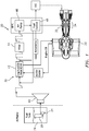
- FIG. 1 schematically illustrates a fuel system 20 for an engine 22.
- the engine 22 may be, for example but not limited to, a gas turbine engine utilized for propulsion of an aircraft, a gas turbine engine utilized as an auxiliary power unit (APU) or other system.
- APU auxiliary power unit
- control of the additive blending operation is performed on-board the vehicle as opposed to relying on ground operations. This also avoids interference with coalescing filters, etc.
- the fuel system 20 may generally include a tank pump 24 to supply fuel from a fuel tank 26 through a passive fuel additives dosing system 28 to a fuel subsystem 30, thence to a fuel manifold 32 in a combustor section 34 of the engine 22.
- the fuel subsystem 30, in one example, may include a boost pump 40, an engine fuel-oil heat exchanger 42, a filter system 44, a highpressure fuel pump 46 and control system 48.
- the fuel subsystem 30 may alternatively or additionally include various components such as multiple fuel tanks, air-oil coolers, fuel driven actuators fuel modules, solenoid valves, metering valves, shut-off valves, spill valves, and other filters.
- the passive fuel additives dosing system 28 will be described primarily as within the low pressure fuel tank 26, the passive fuel additives dosing system 28 may be directly associated with the fuel tank 26 and/or distributed elsewhere in the fuel system 20 such as downstream of the boost pump 40 and upstream of the engine fuel-oil heat exchanger 42; downstream of the engine fuel-oil heat exchanger 42 and upstream of the filter system 44; and/or downstream of the filter system 44 and upstream of the high pressure fuel pump 46.
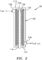
- the passive fuel additives dosing system 28 generally includes a cartridge 100, a membrane-based contactor 102 within the cartridge 100, and an additive 104 within the membrane-based contactor 102.
- the cartridge 100 includes a fuel inlet 106 and a fuel outlet 108 for communication with the fuel subsystem 30.
- the membrane-based contactor 102 is arranged within the cartridge 100 such that, with fuel in the cartridge 100, a fuel contact area with the membrane-based contactor 102 is dependent on a fuel flow rate to passively dispense a proportional amount of the additive 104 into the fuel.
- the membrane-based contactor 102 is sized and oriented within the cartridge 100 to facilitate metering of the fuel contact area with the membrane-based contactor 102 in relation to the fuel flow rate to passively dispense the additive 104.
- the fuel outlet 108 is arranged with respect to the fuel inlet 106 to facilitate metering of the fuel contact area.
- the fuel inlet 106 can be located adjacent a top 110 of the cartridge 100 and the fuel outlet 108 adjacent to a bottom 112 of the cartridge 100. This facilitates draining of the membrane-based contactor 102 once fuel flow has stopped such that osmotic pressure will not continue to drive additives into the fuel which may otherwise result in large concentrations of additives in the remaining volume of fuel. It should be appreciated that relative positional terms such as "top” and "bottom” are with respect to a normal operational attitude of the vehicle such as level flight.
- the membrane-based contactor 102 may include a non-porous or a porous membrane.
- a non-porous membrane may be a reverse selective membrane to permeate large molecules over smaller ones, based on differences in solubility rather than diffusivity.
- Suitable membranes include silicone rubbers, poly-methyl pentyl, and poly-trimethyl-silyl-propyl, and other such reverse selective types.
- Typical polymer non-porous membranes would be unsuitable for this application as membranes such as those typically used for aircraft fuel tank inerting (based on polyimides, polysulfones or polycarbonates) would result in very low permeance of the large molecules comprising the fuel additives package as well as membranes such as those used for fuel stabilization, which are inherently oleophobic (fuel and oil repellent).
- a porous membrane may comprise an oleophobic layer overcoating the outer diameter of a nanoporous polymer film to provide a barrier that facilitates prevention of the fuel from entering into the bore of each hollow fiber while the additives can exit therefrom.
- the porous membrane may have a thickness between about 50 nanometers and about 4 microns with pores of an average pore diameter less than or equal to 0.06 microns.
- the membrane-based contactor 102 may be formed as a bundle of hollow fibers, in which a bore of each fiber contains the additive in a solution, suspension, or emulsion form.
- the relatively large surface area afforded by hollow fibers facilitates effective release of the additive when the flow rate is high.
- the outside surface of each hollow fiber of the bundle of hollow fibers is wetted by the fuel that enters the cartridge 100 from the fuel inlet 106 and exits from the fuel outlet 108.
- Each hollow fiber may include a porous support and a non-porous or porous membrane on an outer diameter of the porous support.
- Other forms of the membrane-based contactor 102 maybe a flat sheet configuration ( FIG. 3 ), a spiral-wound configuration ( FIG. 4 ), or plate-and-frame configuration ( FIG. 5 ).
- examples include both organic (polymeric) and inorganic (e.g. ceramic) membranes.
- the additive can include anti-oxidants such as hindered phenols, metal deactivators, and dispersants that diffuse across the membrane-based contactor 102 due to the difference in osmotic pressure inside and outside of the hollow fibers.
- anti-oxidants such as hindered phenols, metal deactivators, and dispersants that diffuse across the membrane-based contactor 102 due to the difference in osmotic pressure inside and outside of the hollow fibers.
- some or all of the additive can be added as a concentrated liquid that is diluted to meet the specified application.
- the driving force for the additive to permeate the membrane-based contactor 102 is a concentration gradient (higher in the bore, lower in the fuel). Since the hollow fibers are always filled with the additive, the concentration difference between the inside (exposed to the additive) and the outside (exposed to flowing fuel) is essentially constant. Therefore, overall mass transfer is determined by the amount of membrane surface area wetted by the flowing fuel. This, in turn, is determined by the fuel flow rate and a recommended additive
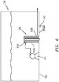
- the cartridge 100 in one embodiment, is located at a bottom 50 of the fuel tank 26 with the fuel outlet 108 adjacent to a tank fuel drain 52 in the fuel tank 26 to facilitate draining of fuel from the cartridge 100 ( FIG. 6 ).
- An additive inlet 114 FIG. 2 ) for refilling the additive is located at the bottom 112 of the cartridge 100.
- the additive inlet 114 communicates with a manifold 116 adjacent to the top 110 of the cartridge 100.
- the manifold 116 supplies additive by gravity such that the hollow fibers are always filled with the additive. Replenishment of the manifold 116 may occur over various intervals and may be conveniently performed at regular intervals as typical operators drain fuel tanks daily to avoid accumulation of water in the fuel tank. Alternatively, the entire cartridge 100 may be replaceable.
- the passive fuel additives dosing system 28 is a relatively uncomplicated, passive osmotic dispenser device that leverages osmotic pressure, as opposed to a power source with dosing properties tuned by the characteristics of the membrane-based contactor 102 as opposed to complex control systems.
Landscapes
- Engineering & Computer Science (AREA)
- Chemical & Material Sciences (AREA)
- Combustion & Propulsion (AREA)
- Mechanical Engineering (AREA)
- General Engineering & Computer Science (AREA)
- Aviation & Aerospace Engineering (AREA)
- Separation Using Semi-Permeable Membranes (AREA)
Applications Claiming Priority (1)
| Application Number | Priority Date | Filing Date | Title |
|---|---|---|---|
| US15/942,982 US10823072B2 (en) | 2018-04-02 | 2018-04-02 | Passive fuel additives dosing system |
Publications (2)
| Publication Number | Publication Date |
|---|---|
| EP3550125A1 true EP3550125A1 (fr) | 2019-10-09 |
| EP3550125B1 EP3550125B1 (fr) | 2024-02-14 |
Family
ID=66049042
Family Applications (1)
| Application Number | Title | Priority Date | Filing Date |
|---|---|---|---|
| EP19166494.5A Active EP3550125B1 (fr) | 2018-04-02 | 2019-04-01 | Système de dosage d'additifs de carburant passifs |
Country Status (2)
| Country | Link |
|---|---|
| US (1) | US10823072B2 (fr) |
| EP (1) | EP3550125B1 (fr) |
Families Citing this family (1)
| Publication number | Priority date | Publication date | Assignee | Title |
|---|---|---|---|---|
| US11193420B2 (en) * | 2018-11-16 | 2021-12-07 | United Technologies Corporation | System and method for monitoring fuel additives |
Citations (3)
| Publication number | Priority date | Publication date | Assignee | Title |
|---|---|---|---|---|
| US20040026291A1 (en) * | 2001-08-24 | 2004-02-12 | Drozd Joseph C. | Controlled release additives in fuel systems |
| US6835218B1 (en) * | 2001-08-24 | 2004-12-28 | Dober Chemical Corp. | Fuel additive compositions |
| US20060086738A1 (en) * | 2002-08-01 | 2006-04-27 | Briggs & Stratton Corporation | Cap for a fuel container |
Family Cites Families (17)
| Publication number | Priority date | Publication date | Assignee | Title |
|---|---|---|---|---|
| US4346689A (en) | 1980-12-09 | 1982-08-31 | Neely Noah A | Controlled fuel injection system |
| US6315815B1 (en) | 1999-12-16 | 2001-11-13 | United Technologies Corporation | Membrane based fuel deoxygenator |
| US6623636B2 (en) | 2000-05-08 | 2003-09-23 | Honeywell International Inc. | Staged oil filter incorporating timed release oil conditioner |
| AUPQ984500A0 (en) | 2000-09-01 | 2000-09-28 | National Valve & Engineering Company Pty. Limited | Multi-additive injection system for aviation fuel |
| US6709492B1 (en) | 2003-04-04 | 2004-03-23 | United Technologies Corporation | Planar membrane deoxygenator |
| US7744827B2 (en) | 2004-02-13 | 2010-06-29 | United Technologies Corporation | Catalytic treatment of fuel to impart coking resistance |
| US7431818B2 (en) | 2004-03-26 | 2008-10-07 | United Technologies Corporation | Electrochemical fuel deoxygenation system |
| US7393388B2 (en) | 2005-05-13 | 2008-07-01 | United Technologies Corporation | Spiral wound fuel stabilization unit for fuel de-oxygenation |
| US8648596B2 (en) | 2006-10-31 | 2014-02-11 | Active Spectrum, Inc. | Method of and apparatus for analysis of the composition of a sample by electron spin resonance (ESR) spectrometry employing carrier suppression |
| US8210826B2 (en) | 2006-04-15 | 2012-07-03 | William Freeman | Controlled liquid injection and blending apparatus |
| US7950216B2 (en) | 2007-01-30 | 2011-05-31 | Pratt & Whitney Canada Corp. | Gas turbine engine fuel control system |
| US8702995B2 (en) | 2008-05-27 | 2014-04-22 | Dober Chemical Corp. | Controlled release of microbiocides |
| US8468982B2 (en) | 2009-03-09 | 2013-06-25 | GM Global Technology Operations LLC | Systems and methods for dispensing oil and fuel additives |
| US20100242490A1 (en) | 2009-03-31 | 2010-09-30 | General Electric Company | Additive delivery systems and methods |
| FR2971016B1 (fr) | 2011-02-02 | 2015-08-07 | Filtrauto | Dispositif de distribution d'un additif |
| CA2848075C (fr) | 2011-09-07 | 2018-12-04 | Afton Chemical Corporation | Systeme de distribution d'additifs de moteur aerien |
| KR101376464B1 (ko) | 2012-11-28 | 2014-03-19 | (주) 유니크코리아엔아이 | 디젤선박 연비향상을 위한 첨가제 농도측정용 센서모듈 |
-
2018
- 2018-04-02 US US15/942,982 patent/US10823072B2/en active Active
-
2019
- 2019-04-01 EP EP19166494.5A patent/EP3550125B1/fr active Active
Patent Citations (3)
| Publication number | Priority date | Publication date | Assignee | Title |
|---|---|---|---|---|
| US20040026291A1 (en) * | 2001-08-24 | 2004-02-12 | Drozd Joseph C. | Controlled release additives in fuel systems |
| US6835218B1 (en) * | 2001-08-24 | 2004-12-28 | Dober Chemical Corp. | Fuel additive compositions |
| US20060086738A1 (en) * | 2002-08-01 | 2006-04-27 | Briggs & Stratton Corporation | Cap for a fuel container |
Also Published As
| Publication number | Publication date |
|---|---|
| US20190301368A1 (en) | 2019-10-03 |
| EP3550125B1 (fr) | 2024-02-14 |
| US10823072B2 (en) | 2020-11-03 |
Similar Documents
| Publication | Publication Date | Title |
|---|---|---|
| EP3034409B1 (fr) | Système de désoxygénation de carburant d'aéronef | |
| US10478780B2 (en) | Separating device for separating at least one undesired fluid from a liquid, membrane of a separating device, filter, filter element, and liquid system | |
| EP1810741B1 (fr) | Désoxygénateur de combustible avec circuit de carburant non planaire et membrane perméable à l'oxygène | |
| US4790941A (en) | Fluid decontamination system | |
| US4850498A (en) | Fluid decontamination system | |
| JPH01138364A (ja) | 燃料送出し装置 | |
| EP3550125B1 (fr) | Système de dosage d'additifs de carburant passifs | |
| EP2570469A1 (fr) | Fractionnement de carburant au moyen de la distillation sur membrane | |
| US4844804A (en) | Fluid decontamination system | |
| US20190209971A1 (en) | Fuel fractioning unit for inert gas generating system | |
| KR20090043549A (ko) | 가스 동력 내부 연소 엔진용 오일 분리기 | |
| EP2784299A1 (fr) | Stabilisation de carburant diesel pour une combustion améliorée | |
| US20180274505A1 (en) | Fuel filter system with water emulsifier | |
| US11879388B2 (en) | System and method for monitoring fuel additives | |
| EP3398670A1 (fr) | Systèmes à vide pour dégazer des combustibles hydrocarbonés liquides | |
| EP3434752A1 (fr) | Système de désoxygénation de réservoir de carburant | |
| EP3434347A1 (fr) | Système de désoxygénation de réservoir de carburant | |
| EP1538330B1 (fr) | System d'alimentation de carburant auto-purgant pour un moteur diesel avec pompe d'alimentation remplissée par gravitation | |
| US20220401895A1 (en) | Process for reducing injector deposits | |
| Ayrancı | Design and performance evaluation of a fuel filter | |
| US20200197835A1 (en) | Composite hollow fiber membranes for jet fuel de-oxygenation | |
| EP3539880A1 (fr) | Atténuation de la cavitation dans des systèmes d'inertage de réservoir de carburant à oxydation catalytique | |
| DE10338227A1 (de) | Fahrzeug mit einer Vorrichtung zur Abtrennung einzelner Kraftstoffkomponenten aus einem Kraftstoffgemisch | |
| WO2016174299A1 (fr) | Dispositif d'alimentation en carburant destiné à un moteur à combustion interne et procédé de filtration de carburant dans un dispositif d'alimentation en carburant d'un moteur à combustion interne | |
| WO2008008749A2 (fr) | Dispositifs et procédés pour séparer de l'eau à partir d'un mélange liquide comprenant un hydrocarbure liquide |
Legal Events
| Date | Code | Title | Description |
|---|---|---|---|
| PUAI | Public reference made under article 153(3) epc to a published international application that has entered the european phase |
Free format text: ORIGINAL CODE: 0009012 |
|
| STAA | Information on the status of an ep patent application or granted ep patent |
Free format text: STATUS: THE APPLICATION HAS BEEN PUBLISHED |
|
| AK | Designated contracting states |
Kind code of ref document: A1 Designated state(s): AL AT BE BG CH CY CZ DE DK EE ES FI FR GB GR HR HU IE IS IT LI LT LU LV MC MK MT NL NO PL PT RO RS SE SI SK SM TR |
|
| AX | Request for extension of the european patent |
Extension state: BA ME |
|
| STAA | Information on the status of an ep patent application or granted ep patent |
Free format text: STATUS: REQUEST FOR EXAMINATION WAS MADE |
|
| 17P | Request for examination filed |
Effective date: 20200406 |
|
| RBV | Designated contracting states (corrected) |
Designated state(s): AL AT BE BG CH CY CZ DE DK EE ES FI FR GB GR HR HU IE IS IT LI LT LU LV MC MK MT NL NO PL PT RO RS SE SI SK SM TR |
|
| RAP1 | Party data changed (applicant data changed or rights of an application transferred) |
Owner name: RAYTHEON TECHNOLOGIES CORPORATION |
|
| STAA | Information on the status of an ep patent application or granted ep patent |
Free format text: STATUS: EXAMINATION IS IN PROGRESS |
|
| 17Q | First examination report despatched |
Effective date: 20210722 |
|
| GRAP | Despatch of communication of intention to grant a patent |
Free format text: ORIGINAL CODE: EPIDOSNIGR1 |
|
| STAA | Information on the status of an ep patent application or granted ep patent |
Free format text: STATUS: GRANT OF PATENT IS INTENDED |
|
| INTG | Intention to grant announced |
Effective date: 20230908 |
|
| RAP3 | Party data changed (applicant data changed or rights of an application transferred) |
Owner name: RTX CORPORATION |
|
| GRAS | Grant fee paid |
Free format text: ORIGINAL CODE: EPIDOSNIGR3 |
|
| GRAA | (expected) grant |
Free format text: ORIGINAL CODE: 0009210 |
|
| STAA | Information on the status of an ep patent application or granted ep patent |
Free format text: STATUS: THE PATENT HAS BEEN GRANTED |
|
| AK | Designated contracting states |
Kind code of ref document: B1 Designated state(s): AL AT BE BG CH CY CZ DE DK EE ES FI FR GB GR HR HU IE IS IT LI LT LU LV MC MK MT NL NO PL PT RO RS SE SI SK SM TR |
|
| REG | Reference to a national code |
Ref country code: GB Ref legal event code: FG4D |
|
| REG | Reference to a national code |
Ref country code: CH Ref legal event code: EP |
|
| REG | Reference to a national code |
Ref country code: DE Ref legal event code: R096 Ref document number: 602019046390 Country of ref document: DE |
|
| REG | Reference to a national code |
Ref country code: IE Ref legal event code: FG4D |
|
| PGFP | Annual fee paid to national office [announced via postgrant information from national office to epo] |
Ref country code: GB Payment date: 20240320 Year of fee payment: 6 |