EP3549830A1 - Side air bag device - Google Patents
Side air bag device Download PDFInfo
- Publication number
- EP3549830A1 EP3549830A1 EP17877994.8A EP17877994A EP3549830A1 EP 3549830 A1 EP3549830 A1 EP 3549830A1 EP 17877994 A EP17877994 A EP 17877994A EP 3549830 A1 EP3549830 A1 EP 3549830A1
- Authority
- EP
- European Patent Office
- Prior art keywords
- expansion part
- seat frame
- side expansion
- cushion
- outer side
- Prior art date
- Legal status (The legal status is an assumption and is not a legal conclusion. Google has not performed a legal analysis and makes no representation as to the accuracy of the status listed.)
- Granted
Links
Images



Classifications
-
- B—PERFORMING OPERATIONS; TRANSPORTING
- B60—VEHICLES IN GENERAL
- B60R—VEHICLES, VEHICLE FITTINGS, OR VEHICLE PARTS, NOT OTHERWISE PROVIDED FOR
- B60R21/00—Arrangements or fittings on vehicles for protecting or preventing injuries to occupants or pedestrians in case of accidents or other traffic risks
- B60R21/02—Occupant safety arrangements or fittings, e.g. crash pads
- B60R21/16—Inflatable occupant restraints or confinements designed to inflate upon impact or impending impact, e.g. air bags
- B60R21/20—Arrangements for storing inflatable members in their non-use or deflated condition; Arrangement or mounting of air bag modules or components
- B60R21/207—Arrangements for storing inflatable members in their non-use or deflated condition; Arrangement or mounting of air bag modules or components in vehicle seats
-
- B—PERFORMING OPERATIONS; TRANSPORTING
- B60—VEHICLES IN GENERAL
- B60N—SEATS SPECIALLY ADAPTED FOR VEHICLES; VEHICLE PASSENGER ACCOMMODATION NOT OTHERWISE PROVIDED FOR
- B60N2/00—Seats specially adapted for vehicles; Arrangement or mounting of seats in vehicles
- B60N2/24—Seats specially adapted for vehicles; Arrangement or mounting of seats in vehicles for particular purposes or particular vehicles
- B60N2/42—Seats specially adapted for vehicles; Arrangement or mounting of seats in vehicles for particular purposes or particular vehicles the seat constructed to protect the occupant from the effect of abnormal g-forces, e.g. crash or safety seats
- B60N2/427—Seats or parts thereof displaced during a crash
-
- B—PERFORMING OPERATIONS; TRANSPORTING
- B60—VEHICLES IN GENERAL
- B60R—VEHICLES, VEHICLE FITTINGS, OR VEHICLE PARTS, NOT OTHERWISE PROVIDED FOR
- B60R21/00—Arrangements or fittings on vehicles for protecting or preventing injuries to occupants or pedestrians in case of accidents or other traffic risks
- B60R21/02—Occupant safety arrangements or fittings, e.g. crash pads
- B60R21/16—Inflatable occupant restraints or confinements designed to inflate upon impact or impending impact, e.g. air bags
- B60R21/23—Inflatable members
- B60R21/231—Inflatable members characterised by their shape, construction or spatial configuration
- B60R21/23138—Inflatable members characterised by their shape, construction or spatial configuration specially adapted for side protection
-
- B—PERFORMING OPERATIONS; TRANSPORTING
- B60—VEHICLES IN GENERAL
- B60R—VEHICLES, VEHICLE FITTINGS, OR VEHICLE PARTS, NOT OTHERWISE PROVIDED FOR
- B60R21/00—Arrangements or fittings on vehicles for protecting or preventing injuries to occupants or pedestrians in case of accidents or other traffic risks
- B60R21/02—Occupant safety arrangements or fittings, e.g. crash pads
- B60R21/16—Inflatable occupant restraints or confinements designed to inflate upon impact or impending impact, e.g. air bags
- B60R21/23—Inflatable members
- B60R21/237—Inflatable members characterised by the way they are folded
-
- B—PERFORMING OPERATIONS; TRANSPORTING
- B60—VEHICLES IN GENERAL
- B60R—VEHICLES, VEHICLE FITTINGS, OR VEHICLE PARTS, NOT OTHERWISE PROVIDED FOR
- B60R21/00—Arrangements or fittings on vehicles for protecting or preventing injuries to occupants or pedestrians in case of accidents or other traffic risks
- B60R21/02—Occupant safety arrangements or fittings, e.g. crash pads
- B60R21/16—Inflatable occupant restraints or confinements designed to inflate upon impact or impending impact, e.g. air bags
- B60R2021/161—Inflatable occupant restraints or confinements designed to inflate upon impact or impending impact, e.g. air bags characterised by additional means for controlling deployment trajectory
-
- B—PERFORMING OPERATIONS; TRANSPORTING
- B60—VEHICLES IN GENERAL
- B60R—VEHICLES, VEHICLE FITTINGS, OR VEHICLE PARTS, NOT OTHERWISE PROVIDED FOR
- B60R21/00—Arrangements or fittings on vehicles for protecting or preventing injuries to occupants or pedestrians in case of accidents or other traffic risks
- B60R21/02—Occupant safety arrangements or fittings, e.g. crash pads
- B60R21/16—Inflatable occupant restraints or confinements designed to inflate upon impact or impending impact, e.g. air bags
- B60R21/23—Inflatable members
- B60R21/231—Inflatable members characterised by their shape, construction or spatial configuration
- B60R21/23138—Inflatable members characterised by their shape, construction or spatial configuration specially adapted for side protection
- B60R2021/23146—Inflatable members characterised by their shape, construction or spatial configuration specially adapted for side protection seat mounted
-
- B—PERFORMING OPERATIONS; TRANSPORTING
- B60—VEHICLES IN GENERAL
- B60R—VEHICLES, VEHICLE FITTINGS, OR VEHICLE PARTS, NOT OTHERWISE PROVIDED FOR
- B60R21/00—Arrangements or fittings on vehicles for protecting or preventing injuries to occupants or pedestrians in case of accidents or other traffic risks
- B60R21/02—Occupant safety arrangements or fittings, e.g. crash pads
- B60R21/16—Inflatable occupant restraints or confinements designed to inflate upon impact or impending impact, e.g. air bags
- B60R21/20—Arrangements for storing inflatable members in their non-use or deflated condition; Arrangement or mounting of air bag modules or components
- B60R21/201—Packaging straps or envelopes for inflatable members
Definitions
- the present invention relates to a side airbag device that is provided at a vehicle seat.
- an airbag device is mostly equipped with a vehicle as the standard equipment.
- the airbag device is a safety device being operated in an emergency such as a vehicle collision and protects an occupant by expanding and deploying an airbag cushion (simply described as a "cushion” below) with a gas pressure so as to receive the occupant.
- a front airbag device is provided at a center of a steering wheel so that a driver can be protected from a collision occurred from the forward and backward directions.
- a curtain airbag device is provided near a ceiling above a side window and a side airbag device is provided at a side part of a seat.
- Patent Document 1 a vehicle seat that is equipped with a side airbag device is disclosed in Patent Document 1.
- the folded side airbag 36 is provided inside the seatback 12 and at an outside of the side frame 16A in the vehicle width direction, that is, at an opposite side with respect to an occupant.
- Patent Document 1 Japanese Patent Publication Number 2016-112927 .
- a side airbag device further improvement of an occupant restraint force is required.
- a deployment position of an airbag cushion is set at a position being closer to an occupant.
- a seat pad that is obtained by utilizing such as a urethane material is filled inside the seatback. Therefore, because a storage space of the airbag cushion of the side airbag device is extremely limited, it is difficult to devise methods for the improvement of the occupant restraint force.
- An object of the present invention is to provide a side airbag device that can be efficiently stored inside a seatback and can also improve the occupant restraint force.
- a configuration of a side airbag device includes: a seat frame that is along a side surface of a seatback of a vehicle seat, the seat frame being built in the seatback; an inflator that is attached to an occupant side of the seat frame; and an airbag cushion that receives a gas from the inflator so as to be expanded and deployed.
- the airbag cushion includes: an inner side expansion part that is stored at the occupant side of the seat frame and the inner side expansion part is connected to the inflator; and an outer side expansion part that is continuously provided with the inner side expansion part, the outer side expansion part is stored at an opposite side of the seat frame with respect to the occupant side, and the outer side expansion part receives the gas from the inner side expansion part so as to be expanded and deployed.
- the airbag cushion is stored by being divided into at the occupant side and at the opposite side of the occupant with respect to the seat frame, the limited space of the inside of the seatback can be efficiently utilized. As a result, it can be applied to various vehicle seats so as to have a high versatility. Further, because the installation space can be made narrow, the miniaturization of the vehicle seat can also be realized.
- the airbag cushion that has the configuration explained above starts to be expanded from the inner side expansion part that is stored at the occupant side of the seat frame, a reaction force directed from the seat frame toward the occupant side can be obtained at an early stage.
- the inner side expansion part is also the basis of the airbag cushion, and according to the configuration explained above, the airbag cushion after being expanded is also located at the position being closer to the occupant. Therefore, according to the configuration explained above, the occupant restraint force can be improved.
- the outer side expansion part is stored in the seatback in a state in which the outer side expansion part directly comes in contact with the seat frame or a state in which the outer side expansion part indirectly comes in contact with the seat frame by sandwiching another member between the outer side expansion part and the seat frame. According to this configuration, when the outer side expansion part is expanded, the reaction force can be efficiently obtained by the seat frame, and an acceleration of the expansion and deployment and the improvement of the occupant restraint force can be realized.
- the airbag cushion device explained above may have a first folded-back part that is located between the inner side expansion part and the outer side expansion part, and the airbag cushion is folded back along a front edge of the seat frame with respect to the first folded-back part. According to this configuration, the airbag cushion can be efficiently stored in the seatback.
- the outer side expansion part explained above may include an outer contact part that directly comes in contact with a predetermined area of the seat frame extending from the front edge of the seat frame toward a vehicle rear or indirectly comes in contact with the predetermined area by sandwiching another member between the outer contact part and the predetermined area, and a second folded-back part with which the outer side expansion part is folded back from a rear end at a vehicle rear side of the outer contact part toward a vehicle front.
- the outer side expansion part pushes the seat frame.
- the outer side expansion part becomes possible to efficiently receive the reaction force by the seat frame.
- the outer side expansion part since the outer side expansion part is expanded and deployed by receiving the reaction force by the seat frame, the acceleration of the expansion and deployment of the entirety of the airbag cushion and the improvement of the occupant restraint force can be realized.
- the outer side expansion part explained above may include an upstream region that extends from the front edge of the seat frame toward the vehicle rear, and a downstream region that is stored between the upstream region and the seat frame.
- the downstream region receives the gas from the upstream region so as to be expanded. According to this configuration, when the gas is flown from the upstream region to the downstream region, the downstream region pushes the seat frame. As a result, the reaction force can also be efficiently obtained by the seat frame, and the acceleration of the expansion and deployment and the improvement of the occupant restraint force can be realized.
- the outer side expansion part explained above may also include a part that is wound. According to this configuration, the outer side expansion part can be efficiently stored in the limited space of the inside of the seatback.
- the outer side expansion part explained above may also include a part that is folded in bellows. According to this configuration, the outer side expansion part can also be efficiently stored in the limited space of the inside of the seatback.
- the inner side expansion part explained above may include an inner contact part that directly comes in contact with the seat frame or indirectly comes in contact with the seat frame by sandwiching another member between the inner contact part and the seat frame and extends from a position to which the inflator is attached toward the front edge of the seat frame, a third folded-back part with which the inner side expansion part is folded back from a front edge at the vehicle front side of the inner contact part toward the vehicle rear, and an inner folding part that further extends from the third folded-back part toward the front edge.
- the inner side contact part pushes the seat frame.
- the inner side contact part becomes possible to efficiently obtain the reaction force directed from the seat frame toward the occupant side.
- the inner side expansion part is located at the upstream side of the flow of the gas in the airbag cushion. Therefore, according to the configuration explained above, because the reaction force directed toward the occupant side can be obtained at an initial stage of the expansion and deployment of the airbag cushion, the acceleration of the expansion and deployment of the entirety of the airbag cushion and the further improvement of the occupant restraint force can be realized.
- the inner side expansion part explained above may also include a part that is wound. According to this configuration, the inner side expansion part can be efficiently stored in the limited space of the inside of the seatback.
- the inner side expansion part explained above may also include a part that is folded in bellows. According to this configuration, the inner side expansion part can also be efficiently stored in the limited space of the inside of the seatback.
- a front edge of the seat frame explained above may be rounded. According to this configuration, the airbag cushion can be stored in the seatback and operated without being damaged.
- a thickness in a vehicle width direction of the front edge of the seat frame may be larger than a thickness in the vehicle width direction of a region rearwardly located from the front edge. According to this configuration, the airbag cushion can also be stored in the seatback and operated without being damaged.
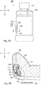
- Fig. 1 is a diagram that exemplarily shows a side airbag device 100 according to an embodiment of the present invention.
- Fig. 1A exemplarily shows the side airbag device 100 and a vehicle seat (a seat 102) that is located on the left side of a vehicle and in which the side airbag device 100 is utilized when viewed from an inner side (a compartment side) in a vehicle width direction.
- a vehicle seat a seat 102
- the vehicle front and rear (longitudinal) direction denotes the arrows F (Forward) and B (Back)
- the vehicle vertical direction denotes the arrows U (Up) and D (Down).
- a seat frame 106 is exemplarily shown by omitting a cover and a seat pad (for instance, a urethane material).
- the seat frame 106 is a member that becomes a framework of the seatback 104 and is built in the seatback 104 along a side surface and an upper edge of the seatback 104.
- An airbag cushion (a cushion 108) is a part being formed in a bag shape by which an occupant is received upon an emergency event such as the occurrence of an impact on the vehicle, and is expanded and deployed in a flat shape toward a side of the occupant (not shown) that sits on the seat 102 by receiving a gas from an inflator 110.
- the cushion 108 is formed in the bag shape by sewing or adhering two stacked base cloths that configure a periphery of the cushion 108, or by spinning and weaving by utilizing the OPW (One-Piece Woven).
- the cushion 108 is built in the vicinity of the side portion of the seat 102.
- the cushion 108 is installed on the seat frame 106 via the inflator 110.
- the cushion 108 and the inflator 110 are installed at a side of a center of the seat frame 106 in the vehicle width direction of the seat 102, i.e., the occupant side of the seat frame 106.
- the inflator 110 is a gas generator and operates by receiving an operation signal that is transmitted from the vehicle side at the occurrence of the impact so as to supply the gas to an inside of the cushion 108.
- the inflator 110 that is adopted in the present embodiment is a cylinder type (a cylindrical type) and is installed at a vehicle rear side of the inside of the cushion 108 in a state in which the longitudinal direction of the inflator 110 aligns with the vertical direction.
- a stud bolt 112 (refer to Fig. 2B ) is provided at the inflator 110. The stud bolt 112 is fastened to the seat frame 106 by penetrating through the cushion 108.
- the inflators that are spread through the market at the present time, such as a model in which a gas generating agent is filled and a gas is generated by burning the gas generating agent, a model in which a compressed gas is filled and a gas is supplied without generating heat, and a hybrid model in which a combustion gas and a compressed gas are used. Any kinds of the inflators can be utilized as the inflator 110.
- Fig. 1B is a diagram that exemplarily shows a state in which the cushion 108 shown in Fig. 1A is stored.
- the airbag cushion 108 is stored inside the seatback 104 in the state in which its size is reduced by being wound and folded.
- the cushion is stored as the cushion sandwiches the seat frame 106 so as to be efficiently stored in the limited space of the inside of the seatback 104.
- the cover 136 maintains the state of the cushion 108 inside the seatback 104 in which the size of the cushion 108 is reduced by being wound and folded.
- the cover 136 can be realized in various forms, such as a configuration of the wrapping by the same material as a base cloth of the cushion 108 or a nonwoven fabric and a configuration of a case-type that is formed by including a resin and a metal. Further, the cover 136 may have a configuration in which the entirety of the cushion 108 is covered. However, the cover 136 can maintain the cushion 108 when the cover 136 has a configuration in which only an area of the predetermined part is covered.
- the cushion 108 can be released by fracturing the cover 136 when the cushion 108 is expanded and deployed.
- the cover 136 is formed by such as the base cloth or the nonwoven fabric
- the fragile part can be realized by such as a broken-line-shaped slit, a nick-shaped notch, an oblong hole-shaped slot, and in addition, a configuration in which ends of the cloths are crimped each other.
- the cover 136 is a container-shaped configuration that is formed by the resin molding, it can also be realized by providing a tear line that is reduced in thickness so as to induce the breakage.
- Fig. 2 is a diagram that exemplarily shows the cushion 108 being in the stored state shown in Fig. 1B when viewed from each of directions.
- Fig. 2A exemplarily shows the seat 102 shown in Fig. 1B when viewed from the vehicle rear side.
- the cushion 108 is stored by being divided into an inner side expansion part 114 at the occupant side and an outer side expansion part 116 at an opposite side of the occupant side with respect to the seat frame 106 so as to sandwich the seat frame 106.
- Fig. 2B is a cross-sectional view along the A - A line of such as the cushion 108 being in the stored state shown in Fig. 2A .
- the inner side expansion part 114 is connected to the inflator 110 and receives the gas from the inflator 110 at the beginning within the cushion 108 so as to be expanded.
- the outer side expansion part 116 is continuously provided with the inner side expansion part 114 and receives the gas from the inner side expansion part 114 so as to be expanded and deployed.
- the cushion 108 being in the stored state is held at the seat frame 106 by being covered with the cover 136 explained above, the cushion 108 can be built in the seatback 104 in a state in which the inner side expansion part 114 and outer side expansion part 116 are formed.
- the cushion 108 is folded back along a front edge 118 of the seat frame 106 between the inner side expansion part 114 and outer side expansion part 116 so that a first folded-back part 115 is provided. According to this configuration, it is possible that the cushion 108 is efficiently stored at the both sides that sandwich the seat frame 106 in the inside of the seatback 104.
- the cushion 108 is stored by being divided into at the occupant side and at the opposite side with respect to the seat frame 106, the limited space of the inside of the seatback 104 in which such as a seat pad 120 is filled can be efficiently utilized.
- the side airbag device 100 can be applied to various vehicle seats that have a wide space or a narrow space with respect to a periphery of the seat frame 106 so as to have a high versatility. Further, because the installation space can be made narrow, the miniaturization of the vehicle seat can also be realized.
- the front edge 118 of the seat frame 106 is bent so as to be rounded.
- a thickness in the vehicle width direction of a region of the front edge 118 is larger to some extent than a thickness in the vehicle width direction of a region rearwardly located from the front edge 118, for instance, such region corresponding to a region that extends in the front and rear direction of the seat and to which the stud bolt 112 of the inflator 110 is fasten.
- the side airbag device 100 because the inner side expansion part 114 and the outer side expansion part 116 are separately stored, it is possible to not only be efficiently stored inside the seatback 104 that is narrow but also improve the acceleration of the expansion and deployment and the occupant restraint force. A further configuration according to the side airbag device 100 will be explained with reference to Fig. 3 below.
- Fig. 3 is a diagram that exemplarily shows a process in which the cushion 108 shown in Fig. 2B is expanded and deployed.
- Fig. 3A exemplarily shows an overview of the cushion 108 being in the stored state shown in Fig. 3B .
- substantial parts of the outer side expansion part 116 are wound so as to reduce (shrink) in size.
- the outer side expansion part 116 can be efficiently stored in the limited space of the inside of the seatback 104.
- Fig. 3B exemplarily shows a state immediately after the inflator 110 shown in Fig. 3A operated.
- the inner side expansion part 114 and the outer side expansion part 116 start to be expanded and deployed.
- the cover 136 is broken at the predetermined fragile part and releases the cushion 108.
- the inner side expansion part 114 that is stored at the occupant side of the seat frame 106 starts to be expanded. At this time, because the inner side expansion part 114 pushes a side surface 122 of the inner side of the seat frame 106 directly or indirectly through the cover 136, the inner side expansion part 114 can receive a reaction force 124. Because the inner side expansion part 114 is located at an upstream of the flow of the gas in the cushion 108, the cushion 108 can receive the reaction force 124 directed from the seat frame 106 toward the occupant side by the inner side expansion part 114 at an early stage.
- the cushion 108 can efficiently push aside, for instance, the seat pad 120 (refer to Fig. 2B ) and the cover 126 so that the cushion 108 can be expanded and deployed more rapidly.
- the outer side expansion part 116 is stored in the seatback 104 in a state in which the outer side expansion part 116 directly comes in contact with the side surface 128 of the outer side of the seat frame 106 or in a state in which the outer side expansion part 116 indirectly comes in contact with the side surface 128 via the cover 136 that is another member.
- the outer side expansion part 116 when the outer side expansion part 116 is expanded, the outer side expansion part 116 can efficiently receive a reaction force 130 by pushing the side surface 128 of the seat frame 106 directly or indirectly through the cover 136. Even when the outer side expansion part 116 receives the reaction force 130 by the seat frame 106, the cushion 108 can be expanded and deployed more rapidly.
- Fig. 3C exemplarily shows a state in which the cushion 108 shown in Fig. 3A is further expanded and deployed.
- the cushion 108 is rapidly expanded and deployed from the inside of the seatback 104 (refer to Fig. 2B ) toward the side of the occupant by utilizing such as the reaction force 124 that the inner side expansion part 114 receives by the seat frame 106 (refer to Fig. 3B ), the reaction force 130 that the outer side expansion part 116 receives by the seat frame 106, and in addition, a force 132 for making the first folded-back part 115 to disappear that is located between the inner side expansion part 114 and the outer side expansion part 116.
- the cushion 108 can perform to push the occupant toward the direction away from the vehicle collision side at an early stage in a detection of an impact and a pre-detection of the impact, that is, the cushion 108 can perform a pre-push function.
- the pre-push function because the occupant is push back to some extent before the entirety of the cushion 108 is expanded, the impact is reduced when the occupant is restrained by the entirety of the cushion 108 so that the injury value of the occupant can be suppressed.
- the inner side expansion part 114 is provided at the occupant side of the seat frame 106, and the inner side expansion part 114 is also the basis of the cushion 108. Therefore, after the cushion 108 is expanded, the cushion 108 is also located at the occupant side of the seat frame 106, that is, the cushion 108 is positioned closer to the occupant. According to this configuration, the occupant restraint force can also be improved.
- Fig. 4 is a diagram that exemplarily shows first and second variations of the cushion 108 shown in Fig. 3 .
- Fig. 4A corresponds to Fig. 3A and exemplarily shows a cushion 140 according to the first variation.
- the cushion 140 is different from the cushion 108 shown in Fig. 3A with respect to a configuration relating to a reduction (shrinkage) method of an outer side expansion part 142.
- the explanations thereof are omitted by accompanying the same reference numerals.
- the basic configuration and functions of these elements are the same as the already explained elements.
- an outer side contact part 143 that comes in contact with a predetermined area of the side surface 128 extending from the front edge 118 toward the vehicle rear is formed at the outer side expansion part 142.
- the outer side contact part 143 is in a state in which the outer side contact part 143 directly comes in contact with the side surface 128 or in a state in which the outer side contact part 143 indirectly comes in contact with the side surface 128 via the cover 136 that is another member.
- a second folded-back part 144 is also formed at the outer side expansion part 142.
- the second folded-back part 144 is formed by being folded back from a rear end at the vehicle rear side of the outer side contact part 143 toward the vehicle front.
- Fig. 4B exemplarily shows a state immediately after the inflator 110 shown in Fig. 4A operated.
- the outer side contact part 143 is expanded first, and thereafter the second folded-back part 144 is expanded so as to make the folded-back to disappear.
- the rest of the outer side expansion part 142 can be expanded and deployed while the rest of the outer side expansion part 142 receives the reaction force 130 by more efficiently pushing the side surface 128 of the seat frame 106.
- the cushion 140 can be expanded and deployed more rapidly from the inside of the seatback 104 (refer to Fig. 2B ) toward the side of the occupant by having the outer side contact part 143 and the second folded-back part 144 so that the occupant restraint force can be improved.
- Fig. 4C corresponds to Fig. 3A and exemplarily shows a cushion 160 according to the second variation.
- the cushion 160 is also different from the cushion 108 shown in Fig. 3A with respect to a configuration relating to a reduction (shrinkage) method of an outer side expansion part 162.
- an upstream region 164 extends from the front edge 118 of the seat frame 106 toward the vehicle rear and is located at the outermost position in the vehicle width direction of the outer side expansion part 162.
- a downstream region 166 that is wound is stored between the upstream region 164 and the seat frame 106.
- the downstream region 166 is a region that is expanded by receiving the gas from the upstream region 164 and is stored in a state in which the downstream region 166 directly comes in contact with the side surface 128 of the seat frame 106 or in a state in which the downstream region 166 indirectly comes in contact with the side surface 128 via the cover 136.
- Fig. 4D exemplarily shows a state immediately after the inflator 110 shown in Fig. 4A operated.
- the outer side expansion part 162 when the gas is flown from the upstream region 164 into the downstream region 164, the downstream region 166 is expanded while the downstream region 166 pushes the side surface 128 of the seat frame 106 directly or indirectly through the cover 136.
- the outer side expansion part 162 can also more efficiently push the side surface 128 of the seat frame 106 so as to receive the reaction force 130.
- the cushion 160 can be expanded and deployed more rapidly from the inside of the seatback 104 (refer to Fig. 2B ) toward the side of the occupant by the upstream region 164 and the downstream region 166 so that the occupant restraint force can be improved.
- Fig. 5 is a diagram that exemplarily shows third and fourth variations of the cushion 108 shown in Fig. 3 .
- Fig. 5A corresponds to Fig. 3A and exemplarily shows a cushion 180 according to the third variation.
- the cushion 180 is also different from the cushion 108 shown in Fig. 3A with respect to a configuration relating to a reduction (shrinkage) method of an outer side expansion part 182.
- the outer side expansion part 182 As exemplarily shown in Fig. 5A , with respect to the outer side expansion part 182, substantial parts are folded in bellows so as to reduce (shrink) in size, and the outer side expansion part 182 are stored in a state in which the outer side expansion part 182 directly comes in contact with the side surface 128 of the seat frame 106 or in a state in which the outer side expansion part 182 indirectly comes in contact with the side surface 128 via the cover 136. According to this configuration, in the same manner as the outer side expansion part 116 that is wound and shown in Fig. 3A , the outer side expansion part 182 can be efficiently stored in the limited space of the inside of the seatback 104 (refer to Fig. 2B ).
- Fig. 5B exemplarily shows a state immediately after the inflator 110 shown in Fig. 5A operated.
- the outer side expansion part 182 because the outer side expansion part 182 is stored in the state in which the outer side expansion part 182 directly or indirectly comes in contact with the side surface 128 of the outside of the seat frame 106, the outer side expansion part 182 can also efficiently receive the reaction force 130 by pushing the side surface 128 of the seat frame 106 directly or indirectly through the cover 136 when the outer side expansion part 182 is expanded. Because the outer side expansion part 182 receives the reaction force 130 by the seat frame 106, the cushion 180 can be expanded and deployed more rapidly.
- the outer side contact part 143 and the second folded-back part 144 shown in Fig. 4A can also be provided in combination with the configuration.
- the outer side expansion part 182 that is folded in bellows can also efficiently receive the reaction force 130 by the seat frame 106.
- the upstream region 164 shown in Fig. 4C is provided and the part being folded in bellows is stored at a corresponding position of the downstream region 166. According to this configuration, the outer side expansion part 182 can also efficiently receive the reaction force 130 by the seat frame 106.
- Fig. 5C is a diagram that exemplarily shows a fourth variation of the cushion 108 shown in Fig. 3 .
- Fig. 5C corresponds to Fig. 3A and exemplarily shows a cushion 200 according to the fourth variation.
- the cushion 200 not only the outer side expansion part 182 are folded in bellows but also an inner side expansion part 202 are folded in bellows. Although the part being folded in bellows is included in the inner side expansion part 202, the cushion 200 can be efficiently stored in the limited space of the inside of the seatback 104 (refer to Fig. 2B ).
- Fig. 5D exemplarily shows a state immediately after the inflator 110 shown in Fig. 5C operated.
- the cushion 200 starts to be expanded from the inner side expansion part 202 that is stored at the occupant side of the seat frame 106.
- the inner side expansion part 202 can be expanded while the inner side expansion part 202 makes the part being folded in bellows to be eliminated (disappear) and receives the reaction force 124 by pushing the side surface 122 of the inner side of the seat frame 106 directly or indirectly through the cover 136.
- the cushion 200 can receive the reaction force 130 directed from the seat frame 106 toward the occupant side by the inner side expansion part 202 at an early stage. Because the inner side expansion part 202 receives the reaction force 130 by the seat frame 106, the cushion 200 can efficiently push aside, for instance, the seat pad 120 (refer to Fig. 2B ) and the cover 126 so that the cushion 200 can be expanded and deployed more rapidly.
- the outer side contact part 143 and the second folded-back part 144 shown in Fig. 4A are combined with the configuration or that the part being folded in bellows is stored at a corresponding position of the downstream region 166 by combining the upstream region 164 shown in Fig. 4C .
- the inner side expansion part 202 can also be provided in combination with the outer side expansion part 116 shown in Fig. 3A , the outer side expansion part 142 shown in Fig. 4B , and the outer side expansion part 162 shown in Fig. 4C .
- Fig. 6 is a diagram that exemplarily shows a fifth variation of the cushion 108 shown in Fig. 3 .
- Fig. 6A corresponds to Fig. 3A and exemplarily shows a cushion 220 according to the fifth variation.
- the cushion 220 not only the outer side expansion part 116 is stored by being wound but also an inner side expansion part 222 is stored by being wound.
- the inner side expansion part 222 includes the part (an inner folding part 224) being reduced in size by winding and folding, the cushion 220 can be efficiently stored in the limited space of the inside of the seatback 104 (refer to Fig. 2B ).
- An inner side contact part 225 and a third folded-back part 226 are also provided at the inner side expansion part 222.
- the inner side contact part 225 extends from a position of the seat frame 106 to which the inflator 110 is attached toward the front edge 118 of the seat frame 106 while the inner side contact part 225 directly comes in contact with the side surface 122 of the seat frame 106 or indirectly comes in contact with the side surface 122 via the cover 136 that is another member.
- the third folded-back part 226 is formed by being folded back from the front edge at the vehicle front of the inner side contact part 225 toward the vehicle rear.
- the inner folding part 224 is provided at a distal position of the third folded-back part 226 and the base cloth of the inner side expansion part 222 extends from the third folded-back part 226 toward the front edge 118 again.
- the inner side contact part 225 when the gas is flown into the inner side expansion part 222, because the inner side contact part 225 is expanded first so that the third folded-back part 226 is expanded so as to eliminate the folded-back, the inner side contact part 225 pushes the side surface 128 of the seat frame 106 directly or indirectly through the cover 136. As a result, it becomes possible that the reaction force 130 directed from the seat frame 106 toward the occupant side is efficiently received immediately after starting the inflow of the gas. Therefore, according to the configuration explained above, because the reaction force 124 directed toward the occupant side can be obtained at the initial stage of the expansion and deployment of the cushion 220, the acceleration of the expansion and deployment and the further improvement of the occupant restraint force can be realized.
- the inner side expansion part 222 can also be provided in combination with any of the outer side expansion parts 116, 142, 162, and 182 explained above. Further, the inner side contact part 225 and the third folded-back part 226 can be provided in combination with the inner side expansion part 222 that is folded in bellows shown in Fig. 5C .
- Fig. 7 is a diagram that exemplarily shows a variation of the seat frame 106 shown in Fig. 3A .
- a seat frame 230 is different from the seat frame 106 shown in Fig. 3A with respect to a configuration of a front edge 232.
- the front edge 232 of the seat frame 230 is thicker in the vehicle width direction.
- a chamfer 234 is provided so as to eliminate an acute angle.
- a thickness in the vehicle width direction of a region of the front edge 232 in which the chamfer 234 is provided is larger to some extent than a thickness in the vehicle width direction of a region rearwardly located from the front edge 232, for instance, such region corresponding to a region that extends in the front and rear direction of the seat and to which the stud bolt 112 of the inflator 110 is fasten.
- the front edge 118 (refer to Fig.
- the cushion 108 can be efficiently stored in the seatback 104 (refer to Fig. 2B ) and can operate without being damaged.
- the present invention can be utilized to a side airbag device that is provided in a vehicle seat.
Landscapes
- Engineering & Computer Science (AREA)
- Mechanical Engineering (AREA)
- Aviation & Aerospace Engineering (AREA)
- Transportation (AREA)
- Air Bags (AREA)
- Seats For Vehicles (AREA)
Abstract
Description
- The present invention relates to a side airbag device that is provided at a vehicle seat.
- In the recent years, an airbag device is mostly equipped with a vehicle as the standard equipment. The airbag device is a safety device being operated in an emergency such as a vehicle collision and protects an occupant by expanding and deploying an airbag cushion (simply described as a "cushion" below) with a gas pressure so as to receive the occupant.
- There are various kinds of airbag devices according to the installation positions and the use. For instance, a front airbag device is provided at a center of a steering wheel so that a driver can be protected from a collision occurred from the forward and backward directions. In addition, in order to protect an occupant from an impact in a vehicle width direction by such as a side collision, a curtain airbag device is provided near a ceiling above a side window and a side airbag device is provided at a side part of a seat.
- For instance, a vehicle seat that is equipped with a side airbag device is disclosed in Patent Document 1. In the technology in Patent Documents 1, the folded side airbag 36 is provided inside the seatback 12 and at an outside of the side frame 16A in the vehicle width direction, that is, at an opposite side with respect to an occupant.
- Patent Document 1: Japanese Patent Publication Number
2016-112927 - At the present time, with respect to a side airbag device, further improvement of an occupant restraint force is required. In order to improve the occupant restraint force, it is considered to take the measures that, for instance, a deployment position of an airbag cushion is set at a position being closer to an occupant. However, as shown in, for example,
Fig. 3 and others in Patent Document 1, a seat pad that is obtained by utilizing such as a urethane material is filled inside the seatback. Therefore, because a storage space of the airbag cushion of the side airbag device is extremely limited, it is difficult to devise methods for the improvement of the occupant restraint force. - The present invention attempts to solve these problems. An object of the present invention is to provide a side airbag device that can be efficiently stored inside a seatback and can also improve the occupant restraint force.
- In order to solve the above problems, a configuration of a side airbag device according to the present invention includes: a seat frame that is along a side surface of a seatback of a vehicle seat, the seat frame being built in the seatback; an inflator that is attached to an occupant side of the seat frame; and an airbag cushion that receives a gas from the inflator so as to be expanded and deployed. The airbag cushion includes: an inner side expansion part that is stored at the occupant side of the seat frame and the inner side expansion part is connected to the inflator; and an outer side expansion part that is continuously provided with the inner side expansion part, the outer side expansion part is stored at an opposite side of the seat frame with respect to the occupant side, and the outer side expansion part receives the gas from the inner side expansion part so as to be expanded and deployed.
- According to the configuration explained above, because the airbag cushion is stored by being divided into at the occupant side and at the opposite side of the occupant with respect to the seat frame, the limited space of the inside of the seatback can be efficiently utilized. As a result, it can be applied to various vehicle seats so as to have a high versatility. Further, because the installation space can be made narrow, the miniaturization of the vehicle seat can also be realized.
- In addition, because the airbag cushion that has the configuration explained above starts to be expanded from the inner side expansion part that is stored at the occupant side of the seat frame, a reaction force directed from the seat frame toward the occupant side can be obtained at an early stage. The inner side expansion part is also the basis of the airbag cushion, and according to the configuration explained above, the airbag cushion after being expanded is also located at the position being closer to the occupant. Therefore, according to the configuration explained above, the occupant restraint force can be improved.
- In the side airbag device, the outer side expansion part is stored in the seatback in a state in which the outer side expansion part directly comes in contact with the seat frame or a state in which the outer side expansion part indirectly comes in contact with the seat frame by sandwiching another member between the outer side expansion part and the seat frame. According to this configuration, when the outer side expansion part is expanded, the reaction force can be efficiently obtained by the seat frame, and an acceleration of the expansion and deployment and the improvement of the occupant restraint force can be realized.
- The airbag cushion device explained above may have a first folded-back part that is located between the inner side expansion part and the outer side expansion part, and the airbag cushion is folded back along a front edge of the seat frame with respect to the first folded-back part. According to this configuration, the airbag cushion can be efficiently stored in the seatback.
- The outer side expansion part explained above may include an outer contact part that directly comes in contact with a predetermined area of the seat frame extending from the front edge of the seat frame toward a vehicle rear or indirectly comes in contact with the predetermined area by sandwiching another member between the outer contact part and the predetermined area, and a second folded-back part with which the outer side expansion part is folded back from a rear end at a vehicle rear side of the outer contact part toward a vehicle front. According to this configuration, when the gas is flown into the outer side expansion part, due to the expansion of the outer side contact part and due to the expansion so as to make the second folded-back part to disappear, the outer side expansion part pushes the seat frame. As a result, the outer side expansion part becomes possible to efficiently receive the reaction force by the seat frame. Further, since the outer side expansion part is expanded and deployed by receiving the reaction force by the seat frame, the acceleration of the expansion and deployment of the entirety of the airbag cushion and the improvement of the occupant restraint force can be realized.
- The outer side expansion part explained above may include an upstream region that extends from the front edge of the seat frame toward the vehicle rear, and a downstream region that is stored between the upstream region and the seat frame. The downstream region receives the gas from the upstream region so as to be expanded. According to this configuration, when the gas is flown from the upstream region to the downstream region, the downstream region pushes the seat frame. As a result, the reaction force can also be efficiently obtained by the seat frame, and the acceleration of the expansion and deployment and the improvement of the occupant restraint force can be realized.
- The outer side expansion part explained above may also include a part that is wound. According to this configuration, the outer side expansion part can be efficiently stored in the limited space of the inside of the seatback.
- The outer side expansion part explained above may also include a part that is folded in bellows. According to this configuration, the outer side expansion part can also be efficiently stored in the limited space of the inside of the seatback.
- The inner side expansion part explained above may include an inner contact part that directly comes in contact with the seat frame or indirectly comes in contact with the seat frame by sandwiching another member between the inner contact part and the seat frame and extends from a position to which the inflator is attached toward the front edge of the seat frame, a third folded-back part with which the inner side expansion part is folded back from a front edge at the vehicle front side of the inner contact part toward the vehicle rear, and an inner folding part that further extends from the third folded-back part toward the front edge.
- According to the configuration explained above, when the gas is flown into the inner side expansion part, due to the expansion of the inner side contact part and due to the expansion so as to make the third folded-back part to disappear, the inner side contact part pushes the seat frame. As a result, the inner side contact part becomes possible to efficiently obtain the reaction force directed from the seat frame toward the occupant side. In particular, the inner side expansion part is located at the upstream side of the flow of the gas in the airbag cushion. Therefore, according to the configuration explained above, because the reaction force directed toward the occupant side can be obtained at an initial stage of the expansion and deployment of the airbag cushion, the acceleration of the expansion and deployment of the entirety of the airbag cushion and the further improvement of the occupant restraint force can be realized.
- The inner side expansion part explained above may also include a part that is wound. According to this configuration, the inner side expansion part can be efficiently stored in the limited space of the inside of the seatback.
- The inner side expansion part explained above may also include a part that is folded in bellows. According to this configuration, the inner side expansion part can also be efficiently stored in the limited space of the inside of the seatback.
- With respect to the side airbag device, a front edge of the seat frame explained above may be rounded. According to this configuration, the airbag cushion can be stored in the seatback and operated without being damaged.
- With respect to the seat frame explained above, a thickness in a vehicle width direction of the front edge of the seat frame may be larger than a thickness in the vehicle width direction of a region rearwardly located from the front edge. According to this configuration, the airbag cushion can also be stored in the seatback and operated without being damaged.
- According to the present invention, it becomes possible to provide a side airbag device that can be efficiently stored in a seatback and can also achieve the improvement of the occupant restraint force.
-
-
Figs. 1A and 1B are diagrams that exemplarily show a side airbag device according to an embodiment of the present invention. -
Figs. 2A and 2B are diagrams that exemplarily show a cushion being in a stored state shown inFig. 1B viewed from each of directions. -
Figs. 3A, 3B, and 3C are diagrams that exemplarily show a process in which the cushion shown inFig. 2B is expanded and deployed. -
Figs. 4A, 4B, 4C, and 4D are diagrams that exemplarily show first and second variations of the cushion shown inFig. 3 . -
Figs. 5A, 5B, 5C, and 5D are diagrams that exemplarily show third and fourth variations of the cushion shown inFig. 3 . -
Figs. 6A and 6B are diagrams that exemplarily show a fifth variation of the cushion shown inFig. 3 . -
Fig. 7 is a diagram that exemplarily shows a variation of a seat frame shown inFig. 3A . - 100 - Side Airbag Device, 102 - Seat, 104 - Seatback, 106 - Seat Frame, 108 - Cushion, 110 - Inflator, 112 - Stud Bolt, 114 - Inner Side Expansion Part, 115 - First Folded-back Part, 116 - Outer Side Expansion Part, 118 - Front Edge of Seat Frame, 120 - Seat Pad, 122 - Side Surface of Inner Side of Seat Frame, 124 - Reaction Force that Inner Side Expansion Part Obtains, 126 - Cover, 128 - Side Surface of Outer Side of Seat Frame, 130 - Reaction Force that Outer Side Expansion Part Obtains, 132 - Force for Making Folded-back between Inner Side Expansion Part and Outer Side Expansion Part to Disappear, 136 - Cover, 140 - Cushion of First Variation, 142 - Outer Side Expansion Part of First Variation, 143 - Outer Side Contact Part, 144 - Second Folded-back Part, 160 - Cushion of Second Variation, 162 - Outer Side Expansion Part of Second Variation, 164 - Upstream Region, 166 - Downstream Region, 180 - Cushion of Third Variation, 182 - Outer Side Expansion Part of Third Variation, 200 - Cushion of Fourth Variation, 202 - Inner Side Expansion Part of Fourth Variation, 220 - Cushion of Fifth Variation, 222 - Inner Side Expansion Part of Fifth Variation, 224 - Inner Folding Part, 225 - Inner Side Contact Part, 226 - Third Folded-back Part, 230 - Seat Frame of Variation, and 232 - Front Edge of Variation.
- Preferred embodiments of the present invention will be explained in detail below with reference to the attached drawings. The dimensions, materials, other concrete numerical values, and other that are disclosed in the embodiments are merely examples for facilitating understanding of the invention, and unless otherwise stated, they do not limit the present invention. Further, in the specification and the drawings, with respect to the elements having substantially the same functions and configurations, redundant explanations are omitted by accompanying the same reference numerals. Further, the elements that are not directly related to the present invention are not shown in the drawings.
-
Fig. 1 is a diagram that exemplarily shows aside airbag device 100 according to an embodiment of the present invention.Fig. 1A exemplarily shows theside airbag device 100 and a vehicle seat (a seat 102) that is located on the left side of a vehicle and in which theside airbag device 100 is utilized when viewed from an inner side (a compartment side) in a vehicle width direction. With respect toFig. 1A and all other drawings according to the present invention, the vehicle front and rear (longitudinal) direction denotes the arrows F (Forward) and B (Back), the vehicle width direction that corresponds to the left and right respectively denotes the arrows L (Left) and R (Right), and the vehicle vertical direction denotes the arrows U (Up) and D (Down). - In
Fig. 1A , with respect to aseatback 104 of aseat 102, only aseat frame 106 is exemplarily shown by omitting a cover and a seat pad (for instance, a urethane material). Theseat frame 106 is a member that becomes a framework of theseatback 104 and is built in theseatback 104 along a side surface and an upper edge of theseatback 104. - An airbag cushion (a cushion 108) is a part being formed in a bag shape by which an occupant is received upon an emergency event such as the occurrence of an impact on the vehicle, and is expanded and deployed in a flat shape toward a side of the occupant (not shown) that sits on the
seat 102 by receiving a gas from aninflator 110. Thecushion 108 is formed in the bag shape by sewing or adhering two stacked base cloths that configure a periphery of thecushion 108, or by spinning and weaving by utilizing the OPW (One-Piece Woven). - In the present embodiment, the
cushion 108 is built in the vicinity of the side portion of theseat 102. Thecushion 108 is installed on theseat frame 106 via theinflator 110. In particular, in the present embodiment, thecushion 108 and the inflator 110 are installed at a side of a center of theseat frame 106 in the vehicle width direction of theseat 102, i.e., the occupant side of theseat frame 106. - The
inflator 110 is a gas generator and operates by receiving an operation signal that is transmitted from the vehicle side at the occurrence of the impact so as to supply the gas to an inside of thecushion 108. The inflator 110 that is adopted in the present embodiment is a cylinder type (a cylindrical type) and is installed at a vehicle rear side of the inside of thecushion 108 in a state in which the longitudinal direction of theinflator 110 aligns with the vertical direction. A stud bolt 112 (refer toFig. 2B ) is provided at theinflator 110. Thestud bolt 112 is fastened to theseat frame 106 by penetrating through thecushion 108. - There are some kinds of the inflators that are spread through the market at the present time, such as a model in which a gas generating agent is filled and a gas is generated by burning the gas generating agent, a model in which a compressed gas is filled and a gas is supplied without generating heat, and a hybrid model in which a combustion gas and a compressed gas are used. Any kinds of the inflators can be utilized as the
inflator 110. -
Fig. 1B is a diagram that exemplarily shows a state in which thecushion 108 shown inFig. 1A is stored. As exemplarily shown inFig. 1B , theairbag cushion 108 is stored inside theseatback 104 in the state in which its size is reduced by being wound and folded. In the present embodiment, the cushion is stored as the cushion sandwiches theseat frame 106 so as to be efficiently stored in the limited space of the inside of theseatback 104. - With respect to the
cushion 108 being in a stored state, its periphery is covered by acover 136. Thecover 136 maintains the state of thecushion 108 inside theseatback 104 in which the size of thecushion 108 is reduced by being wound and folded. Thecover 136 can be realized in various forms, such as a configuration of the wrapping by the same material as a base cloth of thecushion 108 or a nonwoven fabric and a configuration of a case-type that is formed by including a resin and a metal. Further, thecover 136 may have a configuration in which the entirety of thecushion 108 is covered. However, thecover 136 can maintain thecushion 108 when thecover 136 has a configuration in which only an area of the predetermined part is covered. - Because a predetermined fragile part is provided in the
cover 136, thecushion 108 can be released by fracturing thecover 136 when thecushion 108 is expanded and deployed. When thecover 136 is formed by such as the base cloth or the nonwoven fabric, the fragile part can be realized by such as a broken-line-shaped slit, a nick-shaped notch, an oblong hole-shaped slot, and in addition, a configuration in which ends of the cloths are crimped each other. Further, when thecover 136 is a container-shaped configuration that is formed by the resin molding, it can also be realized by providing a tear line that is reduced in thickness so as to induce the breakage. -
Fig. 2 is a diagram that exemplarily shows thecushion 108 being in the stored state shown inFig. 1B when viewed from each of directions.Fig. 2A exemplarily shows theseat 102 shown inFig. 1B when viewed from the vehicle rear side. As exemplarily shown inFig. 2B , thecushion 108 is stored by being divided into an innerside expansion part 114 at the occupant side and an outerside expansion part 116 at an opposite side of the occupant side with respect to theseat frame 106 so as to sandwich theseat frame 106. -
Fig. 2B is a cross-sectional view along the A - A line of such as thecushion 108 being in the stored state shown inFig. 2A . As exemplarily shown inFig. 2B , the innerside expansion part 114 is connected to theinflator 110 and receives the gas from the inflator 110 at the beginning within thecushion 108 so as to be expanded. The outerside expansion part 116 is continuously provided with the innerside expansion part 114 and receives the gas from the innerside expansion part 114 so as to be expanded and deployed. Because thecushion 108 being in the stored state is held at theseat frame 106 by being covered with thecover 136 explained above, thecushion 108 can be built in theseatback 104 in a state in which the innerside expansion part 114 and outerside expansion part 116 are formed. - The
cushion 108 is folded back along afront edge 118 of theseat frame 106 between the innerside expansion part 114 and outerside expansion part 116 so that a first folded-back part 115 is provided. According to this configuration, it is possible that thecushion 108 is efficiently stored at the both sides that sandwich theseat frame 106 in the inside of theseatback 104. - As explained above, in the present embodiment, because the
cushion 108 is stored by being divided into at the occupant side and at the opposite side with respect to theseat frame 106, the limited space of the inside of theseatback 104 in which such as aseat pad 120 is filled can be efficiently utilized. Theside airbag device 100 can be applied to various vehicle seats that have a wide space or a narrow space with respect to a periphery of theseat frame 106 so as to have a high versatility. Further, because the installation space can be made narrow, the miniaturization of the vehicle seat can also be realized. - With respect to the
side airbag device 100, thefront edge 118 of theseat frame 106 is bent so as to be rounded. As a result, with respect to theseat frame 106, a thickness in the vehicle width direction of a region of thefront edge 118 is larger to some extent than a thickness in the vehicle width direction of a region rearwardly located from thefront edge 118, for instance, such region corresponding to a region that extends in the front and rear direction of the seat and to which thestud bolt 112 of theinflator 110 is fasten. When thecushion 108 is stored by being divided into the innerside expansion part 114 and the outerside expansion part 116 and when thecushion 108 is expanded and deployed, thisfront edge 118 does not give a burden to thecushion 108. Therefore, thecushion 108 can be efficiently stored in theseatback 104 and can operate without being damaged. - With respect to the
side airbag device 100, because the innerside expansion part 114 and the outerside expansion part 116 are separately stored, it is possible to not only be efficiently stored inside theseatback 104 that is narrow but also improve the acceleration of the expansion and deployment and the occupant restraint force. A further configuration according to theside airbag device 100 will be explained with reference toFig. 3 below. -
Fig. 3 is a diagram that exemplarily shows a process in which thecushion 108 shown inFig. 2B is expanded and deployed.Fig. 3A exemplarily shows an overview of thecushion 108 being in the stored state shown inFig. 3B . As exemplarily shown inFig. 3A , substantial parts of the outerside expansion part 116 are wound so as to reduce (shrink) in size. As a result, the outerside expansion part 116 can be efficiently stored in the limited space of the inside of theseatback 104. -
Fig. 3B exemplarily shows a state immediately after the inflator 110 shown inFig. 3A operated. As show inFig. 3A , when the gas is supplied from theinflator 110, the innerside expansion part 114 and the outerside expansion part 116 start to be expanded and deployed. By this force, thecover 136 is broken at the predetermined fragile part and releases thecushion 108. - With respect to the
cushion 108, first of all, the innerside expansion part 114 that is stored at the occupant side of theseat frame 106 starts to be expanded. At this time, because the innerside expansion part 114 pushes aside surface 122 of the inner side of theseat frame 106 directly or indirectly through thecover 136, the innerside expansion part 114 can receive areaction force 124. Because the innerside expansion part 114 is located at an upstream of the flow of the gas in thecushion 108, thecushion 108 can receive thereaction force 124 directed from theseat frame 106 toward the occupant side by the innerside expansion part 114 at an early stage. Because of thereaction force 124 that the innerside expansion part 114 receives by theseat frame 106, thecushion 108 can efficiently push aside, for instance, the seat pad 120 (refer toFig. 2B ) and thecover 126 so that thecushion 108 can be expanded and deployed more rapidly. - As exemplarily shown in
Fig. 3A , in the present embodiment, the outerside expansion part 116 is stored in theseatback 104 in a state in which the outerside expansion part 116 directly comes in contact with theside surface 128 of the outer side of theseat frame 106 or in a state in which the outerside expansion part 116 indirectly comes in contact with theside surface 128 via thecover 136 that is another member. According to this configuration, as exemplarily shown inFig. 3B , when the outerside expansion part 116 is expanded, the outerside expansion part 116 can efficiently receive areaction force 130 by pushing theside surface 128 of theseat frame 106 directly or indirectly through thecover 136. Even when the outerside expansion part 116 receives thereaction force 130 by theseat frame 106, thecushion 108 can be expanded and deployed more rapidly. -
Fig. 3C exemplarily shows a state in which thecushion 108 shown inFig. 3A is further expanded and deployed. As explained above, thecushion 108 is rapidly expanded and deployed from the inside of the seatback 104 (refer toFig. 2B ) toward the side of the occupant by utilizing such as thereaction force 124 that the innerside expansion part 114 receives by the seat frame 106 (refer toFig. 3B ), thereaction force 130 that the outerside expansion part 116 receives by theseat frame 106, and in addition, aforce 132 for making the first folded-back part 115 to disappear that is located between the innerside expansion part 114 and the outerside expansion part 116. - As explained above, because the
cushion 108 is rapidly exposed from theseatback 104, thecushion 108 can perform to push the occupant toward the direction away from the vehicle collision side at an early stage in a detection of an impact and a pre-detection of the impact, that is, thecushion 108 can perform a pre-push function. According to the pre-push function, because the occupant is push back to some extent before the entirety of thecushion 108 is expanded, the impact is reduced when the occupant is restrained by the entirety of thecushion 108 so that the injury value of the occupant can be suppressed. - The inner
side expansion part 114 is provided at the occupant side of theseat frame 106, and the innerside expansion part 114 is also the basis of thecushion 108. Therefore, after thecushion 108 is expanded, thecushion 108 is also located at the occupant side of theseat frame 106, that is, thecushion 108 is positioned closer to the occupant. According to this configuration, the occupant restraint force can also be improved. -
Fig. 4 is a diagram that exemplarily shows first and second variations of thecushion 108 shown inFig. 3 .Fig. 4A corresponds toFig. 3A and exemplarily shows acushion 140 according to the first variation. Thecushion 140 is different from thecushion 108 shown inFig. 3A with respect to a configuration relating to a reduction (shrinkage) method of an outerside expansion part 142. In the following descriptions, with respect to the elements that are already explained, the explanations thereof are omitted by accompanying the same reference numerals. Further, when there are the elements that have different reference numerals and when these elements have the same names with the elements that are already explained, the basic configuration and functions of these elements are the same as the already explained elements. - As exemplarily shown in
Fig. 4A , an outerside contact part 143 that comes in contact with a predetermined area of theside surface 128 extending from thefront edge 118 toward the vehicle rear is formed at the outerside expansion part 142. The outerside contact part 143 is in a state in which the outerside contact part 143 directly comes in contact with theside surface 128 or in a state in which the outerside contact part 143 indirectly comes in contact with theside surface 128 via thecover 136 that is another member. - A second folded-
back part 144 is also formed at the outerside expansion part 142. The second folded-back part 144 is formed by being folded back from a rear end at the vehicle rear side of the outerside contact part 143 toward the vehicle front. -
Fig. 4B exemplarily shows a state immediately after the inflator 110 shown inFig. 4A operated. When the gas is flown into the outerside expansion part 142, the outerside contact part 143 is expanded first, and thereafter the second folded-back part 144 is expanded so as to make the folded-back to disappear. As a result, the rest of the outerside expansion part 142 can be expanded and deployed while the rest of the outerside expansion part 142 receives thereaction force 130 by more efficiently pushing theside surface 128 of theseat frame 106. As explained above, thecushion 140 can be expanded and deployed more rapidly from the inside of the seatback 104 (refer toFig. 2B ) toward the side of the occupant by having the outerside contact part 143 and the second folded-back part 144 so that the occupant restraint force can be improved. -
Fig. 4C corresponds toFig. 3A and exemplarily shows acushion 160 according to the second variation. Thecushion 160 is also different from thecushion 108 shown inFig. 3A with respect to a configuration relating to a reduction (shrinkage) method of an outerside expansion part 162. - As exemplarily shown in
Fig. 4C , with respect to the outerside expansion part 162, anupstream region 164 extends from thefront edge 118 of theseat frame 106 toward the vehicle rear and is located at the outermost position in the vehicle width direction of the outerside expansion part 162. Further, adownstream region 166 that is wound is stored between theupstream region 164 and theseat frame 106. Thedownstream region 166 is a region that is expanded by receiving the gas from theupstream region 164 and is stored in a state in which thedownstream region 166 directly comes in contact with theside surface 128 of theseat frame 106 or in a state in which thedownstream region 166 indirectly comes in contact with theside surface 128 via thecover 136. -
Fig. 4D exemplarily shows a state immediately after the inflator 110 shown inFig. 4A operated. With respect to the outerside expansion part 162, when the gas is flown from theupstream region 164 into thedownstream region 164, thedownstream region 166 is expanded while thedownstream region 166 pushes theside surface 128 of theseat frame 106 directly or indirectly through thecover 136. As a result, the outerside expansion part 162 can also more efficiently push theside surface 128 of theseat frame 106 so as to receive thereaction force 130. Thecushion 160 can be expanded and deployed more rapidly from the inside of the seatback 104 (refer toFig. 2B ) toward the side of the occupant by theupstream region 164 and thedownstream region 166 so that the occupant restraint force can be improved. -
Fig. 5 is a diagram that exemplarily shows third and fourth variations of thecushion 108 shown inFig. 3 .Fig. 5A corresponds toFig. 3A and exemplarily shows acushion 180 according to the third variation. Thecushion 180 is also different from thecushion 108 shown inFig. 3A with respect to a configuration relating to a reduction (shrinkage) method of an outerside expansion part 182. - As exemplarily shown in
Fig. 5A , with respect to the outerside expansion part 182, substantial parts are folded in bellows so as to reduce (shrink) in size, and the outerside expansion part 182 are stored in a state in which the outerside expansion part 182 directly comes in contact with theside surface 128 of theseat frame 106 or in a state in which the outerside expansion part 182 indirectly comes in contact with theside surface 128 via thecover 136. According to this configuration, in the same manner as the outerside expansion part 116 that is wound and shown inFig. 3A , the outerside expansion part 182 can be efficiently stored in the limited space of the inside of the seatback 104 (refer toFig. 2B ). -
Fig. 5B exemplarily shows a state immediately after the inflator 110 shown inFig. 5A operated. With respect to thecushion 180, because the outerside expansion part 182 is stored in the state in which the outerside expansion part 182 directly or indirectly comes in contact with theside surface 128 of the outside of theseat frame 106, the outerside expansion part 182 can also efficiently receive thereaction force 130 by pushing theside surface 128 of theseat frame 106 directly or indirectly through thecover 136 when the outerside expansion part 182 is expanded. Because the outerside expansion part 182 receives thereaction force 130 by theseat frame 106, thecushion 180 can be expanded and deployed more rapidly. - With respect to the
cushion 180 shown inFig. 5A , the outerside contact part 143 and the second folded-back part 144 shown inFig. 4A can also be provided in combination with the configuration. By combining the second folded-back part 144 and so on, the outerside expansion part 182 that is folded in bellows can also efficiently receive thereaction force 130 by theseat frame 106. Further, with respect to thecushion 180, it is also possible that theupstream region 164 shown inFig. 4C is provided and the part being folded in bellows is stored at a corresponding position of thedownstream region 166. According to this configuration, the outerside expansion part 182 can also efficiently receive thereaction force 130 by theseat frame 106. -
Fig. 5C is a diagram that exemplarily shows a fourth variation of thecushion 108 shown inFig. 3 .Fig. 5C corresponds toFig. 3A and exemplarily shows acushion 200 according to the fourth variation. With respect to thecushion 200, not only the outerside expansion part 182 are folded in bellows but also an innerside expansion part 202 are folded in bellows. Although the part being folded in bellows is included in the innerside expansion part 202, thecushion 200 can be efficiently stored in the limited space of the inside of the seatback 104 (refer toFig. 2B ). -
Fig. 5D exemplarily shows a state immediately after the inflator 110 shown inFig. 5C operated. As exemplarily shown inFig. 5D , thecushion 200 starts to be expanded from the innerside expansion part 202 that is stored at the occupant side of theseat frame 106. At this time, the innerside expansion part 202 can be expanded while the innerside expansion part 202 makes the part being folded in bellows to be eliminated (disappear) and receives thereaction force 124 by pushing theside surface 122 of the inner side of theseat frame 106 directly or indirectly through thecover 136. Because the innerside expansion part 202 is located at an upstream of the flow of the gas in thecushion 200, thecushion 200 can receive thereaction force 130 directed from theseat frame 106 toward the occupant side by the innerside expansion part 202 at an early stage. Because the innerside expansion part 202 receives thereaction force 130 by theseat frame 106, thecushion 200 can efficiently push aside, for instance, the seat pad 120 (refer toFig. 2B ) and thecover 126 so that thecushion 200 can be expanded and deployed more rapidly. - With respect to the
cushion 200 shown inFig. 5C , in the same manner as thecushion 180 shown inFig. 5A , it is also possible that the outerside contact part 143 and the second folded-back part 144 shown inFig. 4A are combined with the configuration or that the part being folded in bellows is stored at a corresponding position of thedownstream region 166 by combining theupstream region 164 shown inFig. 4C . Further, the innerside expansion part 202 can also be provided in combination with the outerside expansion part 116 shown inFig. 3A , the outerside expansion part 142 shown inFig. 4B , and the outerside expansion part 162 shown inFig. 4C . -
Fig. 6 is a diagram that exemplarily shows a fifth variation of thecushion 108 shown inFig. 3 .Fig. 6A corresponds toFig. 3A and exemplarily shows acushion 220 according to the fifth variation. With respect to thecushion 220, not only the outerside expansion part 116 is stored by being wound but also an innerside expansion part 222 is stored by being wound. Although the innerside expansion part 222 includes the part (an inner folding part 224) being reduced in size by winding and folding, thecushion 220 can be efficiently stored in the limited space of the inside of the seatback 104 (refer toFig. 2B ). - An inner
side contact part 225 and a third folded-back part 226 are also provided at the innerside expansion part 222. The innerside contact part 225 extends from a position of theseat frame 106 to which theinflator 110 is attached toward thefront edge 118 of theseat frame 106 while the innerside contact part 225 directly comes in contact with theside surface 122 of theseat frame 106 or indirectly comes in contact with theside surface 122 via thecover 136 that is another member. - The third folded-
back part 226 is formed by being folded back from the front edge at the vehicle front of the innerside contact part 225 toward the vehicle rear. Theinner folding part 224 is provided at a distal position of the third folded-back part 226 and the base cloth of the innerside expansion part 222 extends from the third folded-back part 226 toward thefront edge 118 again. - According to the configuration explained above, when the gas is flown into the inner
side expansion part 222, because the innerside contact part 225 is expanded first so that the third folded-back part 226 is expanded so as to eliminate the folded-back, the innerside contact part 225 pushes theside surface 128 of theseat frame 106 directly or indirectly through thecover 136. As a result, it becomes possible that thereaction force 130 directed from theseat frame 106 toward the occupant side is efficiently received immediately after starting the inflow of the gas. Therefore, according to the configuration explained above, because thereaction force 124 directed toward the occupant side can be obtained at the initial stage of the expansion and deployment of thecushion 220, the acceleration of the expansion and deployment and the further improvement of the occupant restraint force can be realized. - Further, in the same manner as the inner
side expansion part 202 shown inFig. 5C , the innerside expansion part 222 can also be provided in combination with any of the outerside expansion parts side contact part 225 and the third folded-back part 226 can be provided in combination with the innerside expansion part 222 that is folded in bellows shown inFig. 5C . Variation of Seat Frame -
Fig. 7 is a diagram that exemplarily shows a variation of theseat frame 106 shown inFig. 3A . A seat frame 230 is different from theseat frame 106 shown inFig. 3A with respect to a configuration of afront edge 232. - The
front edge 232 of the seat frame 230 is thicker in the vehicle width direction. In addition, achamfer 234 is provided so as to eliminate an acute angle. In other words, with respect to the seat frame 230, a thickness in the vehicle width direction of a region of thefront edge 232 in which thechamfer 234 is provided is larger to some extent than a thickness in the vehicle width direction of a region rearwardly located from thefront edge 232, for instance, such region corresponding to a region that extends in the front and rear direction of the seat and to which thestud bolt 112 of theinflator 110 is fasten. In the same manner as the front edge 118 (refer toFig. 3A ) that is rounded, when thecushion 108 is stored by being divided into the innerside expansion part 114 and the outerside expansion part 116 and when thecushion 108 is expanded and deployed, thisfront edge 232 also does not give a burden to thecushion 108. Therefore, thecushion 108 can be efficiently stored in the seatback 104 (refer toFig. 2B ) and can operate without being damaged. - Although the preferred embodiments of the present invention have been described with reference to the attached drawings, the above-described embodiments are preferred examples of the present invention, and other embodiments can also be carried out in various ways. Unless there is a limited description in the specification, the present invention should not be limited to the detailed shape, size, configuration, and arrangement of parts shown in the attached drawings. Further, the expressions and terms used in the specification are for illustrative purposes, and unless there is a limited description, the same are not limited thereto.
- Accordingly, it will be apparent to one of ordinary skill in the art to conceive various modifications within the scope of the claims. All such modifications are intended to be included within the technical scope of the present invention.
- The present invention can be utilized to a side airbag device that is provided in a vehicle seat.
Claims (12)
- A side airbag device comprising:a seat frame that is along a side surface of a seatback of a vehicle seat, the seat frame being built in the seatback;an inflator that is attached to an occupant side of the seat frame; andan airbag cushion that receives a gas from the inflator so as to be expanded and deployed,wherein the airbag cushion includes:an inner side expansion part that is stored at the occupant side of the seat frame, the inner side expansion part being connected to the inflator; andan outer side expansion part that is continuously provided with the inner side expansion part, the outer side expansion part being stored at an opposite side of the seat frame with respect to the occupant side, the outer side expansion part receiving the gas from the inner side expansion part so as to be expanded and deployed.
- The side airbag device according to claim 1,
wherein the outer side expansion part is stored in the seatback in a state in which the outer side expansion part directly comes in contact with the seat frame or a state in which the outer side expansion part indirectly comes in contact with the seat frame by sandwiching another member between the outer side expansion part and the seat frame. - The side airbag device according to claims 1 or 2,
wherein the airbag cushion has a first folded-back part that is located between the inner side expansion part and the outer side expansion part, and the airbag cushion is folded back along a front edge of the seat frame with respect to the first folded-back part. - The side airbag device according to claim 3,
wherein the outer side expansion part includes:an outer contact part that directly comes in contact with a predetermined area of the seat frame extending from the front edge of the seat frame toward a vehicle rear or indirectly comes in contact with the predetermined area by sandwiching another member between the outer contact part and the predetermined area; anda second folded-back part with which the outer side expansion part is folded back from a rear end at a vehicle rear side of the outer contact part toward a vehicle front. - The side airbag device according to claim 3,
wherein the outer side expansion part includes:an upstream region that extends from the front edge of the seat frame toward a vehicle rear; anda downstream region that is stored between the upstream region and the seat frame, the downstream region receiving the gas from the upstream region so as to be expanded. - The side airbag device according to any one of claims 1-5,
wherein the outer side expansion part includes a part that is wound. - The side airbag device according to any one of claims 1-6,
wherein the outer side expansion part includes a part that is folded in bellows. - The side airbag device according to any one of claims 1-7,
wherein the inner side expansion part includes:an inner contact part that directly comes in contact with the seat frame or indirectly comes in contact with the seat frame by sandwiching another member between the inner contact part and the seat frame and extends from a position to which the inflator is attached toward a front edge of the seat frame;a third folded-back part with which the inner side expansion part is folded back from a front edge at a vehicle front side of the inner contact part toward a vehicle rear; andan inner folding part that further extends from the third folded-back part toward the front edge. - The side airbag device according to any one of claims 1-8,
wherein the inner side expansion part includes a part that is wound. - The side airbag device according to any one of claims 1-9,
wherein the inner side expansion part includes a part that is folded in bellows. - The side airbag device according to any one of claims 1-10,
wherein a front edge of the seat frame is rounded. - The side airbag device according to any one of claims 1-11,
wherein a thickness in a vehicle width direction of a front edge of the seat frame is larger than a thickness in the vehicle width direction of a region rearwardly located from the front edge.
Applications Claiming Priority (2)
| Application Number | Priority Date | Filing Date | Title |
|---|---|---|---|
| JP2016235919 | 2016-12-05 | ||
| PCT/JP2017/040792 WO2018105324A1 (en) | 2016-12-05 | 2017-11-13 | Side air bag device |
Publications (3)
| Publication Number | Publication Date |
|---|---|
| EP3549830A1 true EP3549830A1 (en) | 2019-10-09 |
| EP3549830A4 EP3549830A4 (en) | 2020-04-22 |
| EP3549830B1 EP3549830B1 (en) | 2024-09-18 |
Family
ID=62491813
Family Applications (1)
| Application Number | Title | Priority Date | Filing Date |
|---|---|---|---|
| EP17877994.8A Active EP3549830B1 (en) | 2016-12-05 | 2017-11-13 | Side air bag device |
Country Status (4)
| Country | Link |
|---|---|
| US (1) | US11104287B2 (en) |
| EP (1) | EP3549830B1 (en) |
| JP (1) | JP6783874B2 (en) |
| WO (1) | WO2018105324A1 (en) |
Cited By (1)
| Publication number | Priority date | Publication date | Assignee | Title |
|---|---|---|---|---|
| EP4005880A1 (en) * | 2020-11-27 | 2022-06-01 | Autoliv Development AB | Side airbag device and method of manufacturing a side airbag device |
Families Citing this family (13)
| Publication number | Priority date | Publication date | Assignee | Title |
|---|---|---|---|---|
| JP7073534B2 (en) * | 2018-12-21 | 2022-05-23 | オートリブ ディベロップメント エービー | A method for manufacturing a side airbag device, a vehicle seat equipped with the side airbag device, and a side airbag device. |
| JP2021054243A (en) * | 2019-09-30 | 2021-04-08 | 豊田合成株式会社 | Far-side airbag device |
| EP4063201B1 (en) * | 2019-11-20 | 2025-02-26 | Autoliv Development AB | Internal seat frame comprising a side airbag device |
| JP7446790B2 (en) * | 2019-11-22 | 2024-03-11 | 株式会社ダイセル | Airbag devices and vehicle seats |
| KR102729838B1 (en) * | 2020-02-16 | 2024-11-14 | 아우토리브 디벨롭먼트 아베 | Airbag devices and vehicle seats |
| JP7312908B2 (en) * | 2020-04-09 | 2023-07-21 | オートリブ ディベロップメント エービー | side airbag device |
| JP7356949B2 (en) * | 2020-05-01 | 2023-10-05 | 株式会社Subaru | Vehicle occupant protection device |
| WO2022080286A1 (en) * | 2020-10-13 | 2022-04-21 | オートリブ ディベロップメント エービー | Side airbag device |
| JP7517186B2 (en) * | 2021-02-02 | 2024-07-17 | トヨタ自動車株式会社 | Vehicle side airbag device, side airbag folding method, and passenger protection device |
| CN117083205A (en) * | 2021-02-17 | 2023-11-17 | 奥托立夫开发公司 | Side airbag device |
| CN116940483A (en) * | 2021-03-31 | 2023-10-24 | 奥托立夫开发公司 | Side airbag device and method for manufacturing same |
| JP7591485B2 (en) * | 2021-10-23 | 2024-11-28 | オートリブ ディベロップメント エービー | Airbag device and manufacturing method |
| JP7728718B2 (en) * | 2022-03-02 | 2025-08-25 | 豊田合成株式会社 | Far side airbag device |
Family Cites Families (15)
| Publication number | Priority date | Publication date | Assignee | Title |
|---|---|---|---|---|
| JP4760533B2 (en) * | 2006-05-26 | 2011-08-31 | 豊田合成株式会社 | Airbag device |
| US7669888B2 (en) * | 2007-07-19 | 2010-03-02 | Toyoda Gosei Co., Ltd. | Side airbag apparatus |
| JP4962185B2 (en) | 2007-07-19 | 2012-06-27 | 豊田合成株式会社 | Side airbag device |
| CN102099227B (en) | 2008-07-15 | 2014-04-16 | 高田-彼得里公开股份有限公司 | Vehicle seat arrangement and airbag arrangement for motor vehicle and method for protecting a vehicle occupant |
| EP2319734B1 (en) * | 2009-11-04 | 2014-10-22 | Autoliv Development AB | A Safety Arrangement |
| CN103228491B (en) * | 2011-01-27 | 2015-03-25 | 丰田自动车株式会社 | Automobile seat containing side-airbag device |
| EP2567870B1 (en) * | 2011-09-09 | 2015-03-25 | Autoliv Development AB | Vehicle seat with an airbag unit |
| JP5942772B2 (en) * | 2012-10-18 | 2016-06-29 | トヨタ自動車株式会社 | Vehicle seat with side airbag device |
| GB2508005B (en) * | 2012-11-16 | 2018-07-18 | Ford Global Tech Llc | Bag-in-bag safety restraint with directional inflation |
| JP6079765B2 (en) | 2014-12-11 | 2017-02-15 | トヨタ自動車株式会社 | Vehicle seat with side airbag device |
| JP6323438B2 (en) * | 2015-12-16 | 2018-05-16 | トヨタ自動車株式会社 | Vehicle seat with side airbag device |
| JP6428666B2 (en) * | 2016-02-10 | 2018-11-28 | トヨタ自動車株式会社 | Vehicle seat with side airbag device |
| JP2017144781A (en) * | 2016-02-15 | 2017-08-24 | トヨタ自動車株式会社 | Seat cushion air bag structure |
| JP6414157B2 (en) * | 2016-07-22 | 2018-10-31 | トヨタ自動車株式会社 | Vehicle occupant restraint system |
| JP6561942B2 (en) * | 2016-08-22 | 2019-08-21 | トヨタ自動車株式会社 | Vehicle seat with side airbag device |
-
2017
- 2017-11-13 US US16/466,090 patent/US11104287B2/en active Active
- 2017-11-13 EP EP17877994.8A patent/EP3549830B1/en active Active
- 2017-11-13 WO PCT/JP2017/040792 patent/WO2018105324A1/en not_active Ceased
- 2017-11-13 JP JP2018554883A patent/JP6783874B2/en active Active
Cited By (1)
| Publication number | Priority date | Publication date | Assignee | Title |
|---|---|---|---|---|
| EP4005880A1 (en) * | 2020-11-27 | 2022-06-01 | Autoliv Development AB | Side airbag device and method of manufacturing a side airbag device |
Also Published As
| Publication number | Publication date |
|---|---|
| EP3549830A4 (en) | 2020-04-22 |
| US11104287B2 (en) | 2021-08-31 |
| JP6783874B2 (en) | 2020-11-11 |
| WO2018105324A1 (en) | 2018-06-14 |
| JPWO2018105324A1 (en) | 2019-10-24 |
| EP3549830B1 (en) | 2024-09-18 |
| US20200062207A1 (en) | 2020-02-27 |
Similar Documents
| Publication | Publication Date | Title |
|---|---|---|
| EP3549830B1 (en) | Side air bag device | |
| KR102362655B1 (en) | side airbag device | |
| US20180222435A1 (en) | Vehicle seat with side airbag device | |
| JP6426553B2 (en) | Occupant protection device | |
| EP3844034B1 (en) | Knee airbag assemblies | |
| JP2009143379A (en) | Side airbag device | |
| EP3357765A1 (en) | Side airbag device | |
| US11766983B2 (en) | Side airbag device | |
| JP6823079B2 (en) | Side airbag device | |
| CN109963754B (en) | side air bag device | |
| CN112009418B (en) | Side airbag device | |
| JP6454404B2 (en) | Airbag device | |
| JP2019137100A (en) | Side airbag device | |
| JPH0986327A (en) | Energy absorption structure on the vehicle body side | |
| JP5888103B2 (en) | Airbag device for vehicle | |
| JP6009655B2 (en) | Airbag device | |
| JP6017270B2 (en) | Airbag device | |
| JP6379444B2 (en) | Airbag device | |
| JP2017095057A (en) | Side airbag device | |
| JP2023142900A (en) | Vehicle airbag device | |
| JP2014121966A (en) | Air bag device | |
| JP2014148198A (en) | Curtain airbag device |
Legal Events
| Date | Code | Title | Description |
|---|---|---|---|
| STAA | Information on the status of an ep patent application or granted ep patent |
Free format text: STATUS: THE INTERNATIONAL PUBLICATION HAS BEEN MADE |
|
| PUAI | Public reference made under article 153(3) epc to a published international application that has entered the european phase |
Free format text: ORIGINAL CODE: 0009012 |
|
| STAA | Information on the status of an ep patent application or granted ep patent |
Free format text: STATUS: REQUEST FOR EXAMINATION WAS MADE |
|
| 17P | Request for examination filed |
Effective date: 20190702 |
|
| AK | Designated contracting states |
Kind code of ref document: A1 Designated state(s): AL AT BE BG CH CY CZ DE DK EE ES FI FR GB GR HR HU IE IS IT LI LT LU LV MC MK MT NL NO PL PT RO RS SE SI SK SM TR |
|
| AX | Request for extension of the european patent |
Extension state: BA ME |
|
| DAV | Request for validation of the european patent (deleted) | ||
| DAX | Request for extension of the european patent (deleted) | ||
| A4 | Supplementary search report drawn up and despatched |
Effective date: 20200324 |
|
| RIC1 | Information provided on ipc code assigned before grant |
Ipc: B60N 2/427 20060101ALI20200318BHEP Ipc: B60R 21/201 20110101ALN20200318BHEP Ipc: B60R 21/207 20060101AFI20200318BHEP |
|
| STAA | Information on the status of an ep patent application or granted ep patent |
Free format text: STATUS: EXAMINATION IS IN PROGRESS |
|
| 17Q | First examination report despatched |
Effective date: 20201030 |
|
| GRAP | Despatch of communication of intention to grant a patent |
Free format text: ORIGINAL CODE: EPIDOSNIGR1 |
|
| STAA | Information on the status of an ep patent application or granted ep patent |
Free format text: STATUS: GRANT OF PATENT IS INTENDED |
|
| RIC1 | Information provided on ipc code assigned before grant |
Ipc: B60R 21/201 20110101ALN20240320BHEP Ipc: B60N 2/427 20060101ALI20240320BHEP Ipc: B60R 21/207 20060101AFI20240320BHEP |
|
| INTG | Intention to grant announced |
Effective date: 20240409 |
|
| GRAS | Grant fee paid |
Free format text: ORIGINAL CODE: EPIDOSNIGR3 |
|
| GRAA | (expected) grant |
Free format text: ORIGINAL CODE: 0009210 |
|
| STAA | Information on the status of an ep patent application or granted ep patent |
Free format text: STATUS: THE PATENT HAS BEEN GRANTED |
|
| AK | Designated contracting states |
Kind code of ref document: B1 Designated state(s): AL AT BE BG CH CY CZ DE DK EE ES FI FR GB GR HR HU IE IS IT LI LT LU LV MC MK MT NL NO PL PT RO RS SE SI SK SM TR |
|
| REG | Reference to a national code |
Ref country code: GB Ref legal event code: FG4D |
|
| REG | Reference to a national code |
Ref country code: CH Ref legal event code: EP |
|
| REG | Reference to a national code |
Ref country code: IE Ref legal event code: FG4D |
|
| REG | Reference to a national code |
Ref country code: DE Ref legal event code: R096 Ref document number: 602017084973 Country of ref document: DE |
|
| REG | Reference to a national code |
Ref country code: LT Ref legal event code: MG9D |
|
| PG25 | Lapsed in a contracting state [announced via postgrant information from national office to epo] |
Ref country code: NO Free format text: LAPSE BECAUSE OF FAILURE TO SUBMIT A TRANSLATION OF THE DESCRIPTION OR TO PAY THE FEE WITHIN THE PRESCRIBED TIME-LIMIT Effective date: 20241218 |
|
| PG25 | Lapsed in a contracting state [announced via postgrant information from national office to epo] |
Ref country code: GR Free format text: LAPSE BECAUSE OF FAILURE TO SUBMIT A TRANSLATION OF THE DESCRIPTION OR TO PAY THE FEE WITHIN THE PRESCRIBED TIME-LIMIT Effective date: 20241219 Ref country code: FI Free format text: LAPSE BECAUSE OF FAILURE TO SUBMIT A TRANSLATION OF THE DESCRIPTION OR TO PAY THE FEE WITHIN THE PRESCRIBED TIME-LIMIT Effective date: 20240918 |
|
| PG25 | Lapsed in a contracting state [announced via postgrant information from national office to epo] |
Ref country code: BG Free format text: LAPSE BECAUSE OF FAILURE TO SUBMIT A TRANSLATION OF THE DESCRIPTION OR TO PAY THE FEE WITHIN THE PRESCRIBED TIME-LIMIT Effective date: 20240918 |
|
| PG25 | Lapsed in a contracting state [announced via postgrant information from national office to epo] |
Ref country code: LV Free format text: LAPSE BECAUSE OF FAILURE TO SUBMIT A TRANSLATION OF THE DESCRIPTION OR TO PAY THE FEE WITHIN THE PRESCRIBED TIME-LIMIT Effective date: 20240918 |
|
| PG25 | Lapsed in a contracting state [announced via postgrant information from national office to epo] |
Ref country code: HR Free format text: LAPSE BECAUSE OF FAILURE TO SUBMIT A TRANSLATION OF THE DESCRIPTION OR TO PAY THE FEE WITHIN THE PRESCRIBED TIME-LIMIT Effective date: 20240918 |
|
| REG | Reference to a national code |
Ref country code: NL Ref legal event code: MP Effective date: 20240918 |
|
| PG25 | Lapsed in a contracting state [announced via postgrant information from national office to epo] |
Ref country code: RS Free format text: LAPSE BECAUSE OF FAILURE TO SUBMIT A TRANSLATION OF THE DESCRIPTION OR TO PAY THE FEE WITHIN THE PRESCRIBED TIME-LIMIT Effective date: 20241218 |
|
| PG25 | Lapsed in a contracting state [announced via postgrant information from national office to epo] |
Ref country code: RS Free format text: LAPSE BECAUSE OF FAILURE TO SUBMIT A TRANSLATION OF THE DESCRIPTION OR TO PAY THE FEE WITHIN THE PRESCRIBED TIME-LIMIT Effective date: 20241218 Ref country code: NO Free format text: LAPSE BECAUSE OF FAILURE TO SUBMIT A TRANSLATION OF THE DESCRIPTION OR TO PAY THE FEE WITHIN THE PRESCRIBED TIME-LIMIT Effective date: 20241218 Ref country code: LV Free format text: LAPSE BECAUSE OF FAILURE TO SUBMIT A TRANSLATION OF THE DESCRIPTION OR TO PAY THE FEE WITHIN THE PRESCRIBED TIME-LIMIT Effective date: 20240918 Ref country code: HR Free format text: LAPSE BECAUSE OF FAILURE TO SUBMIT A TRANSLATION OF THE DESCRIPTION OR TO PAY THE FEE WITHIN THE PRESCRIBED TIME-LIMIT Effective date: 20240918 Ref country code: GR Free format text: LAPSE BECAUSE OF FAILURE TO SUBMIT A TRANSLATION OF THE DESCRIPTION OR TO PAY THE FEE WITHIN THE PRESCRIBED TIME-LIMIT Effective date: 20241219 Ref country code: FI Free format text: LAPSE BECAUSE OF FAILURE TO SUBMIT A TRANSLATION OF THE DESCRIPTION OR TO PAY THE FEE WITHIN THE PRESCRIBED TIME-LIMIT Effective date: 20240918 Ref country code: BG Free format text: LAPSE BECAUSE OF FAILURE TO SUBMIT A TRANSLATION OF THE DESCRIPTION OR TO PAY THE FEE WITHIN THE PRESCRIBED TIME-LIMIT Effective date: 20240918 |
|
| REG | Reference to a national code |
Ref country code: AT Ref legal event code: MK05 Ref document number: 1724443 Country of ref document: AT Kind code of ref document: T Effective date: 20240918 |
|
| PG25 | Lapsed in a contracting state [announced via postgrant information from national office to epo] |
Ref country code: NL Free format text: LAPSE BECAUSE OF FAILURE TO SUBMIT A TRANSLATION OF THE DESCRIPTION OR TO PAY THE FEE WITHIN THE PRESCRIBED TIME-LIMIT Effective date: 20240918 |
|
| PG25 | Lapsed in a contracting state [announced via postgrant information from national office to epo] |
Ref country code: IS Free format text: LAPSE BECAUSE OF FAILURE TO SUBMIT A TRANSLATION OF THE DESCRIPTION OR TO PAY THE FEE WITHIN THE PRESCRIBED TIME-LIMIT Effective date: 20250118 Ref country code: PT Free format text: LAPSE BECAUSE OF FAILURE TO SUBMIT A TRANSLATION OF THE DESCRIPTION OR TO PAY THE FEE WITHIN THE PRESCRIBED TIME-LIMIT Effective date: 20250120 |
|
| PG25 | Lapsed in a contracting state [announced via postgrant information from national office to epo] |
Ref country code: RO Free format text: LAPSE BECAUSE OF FAILURE TO SUBMIT A TRANSLATION OF THE DESCRIPTION OR TO PAY THE FEE WITHIN THE PRESCRIBED TIME-LIMIT Effective date: 20240918 Ref country code: SM Free format text: LAPSE BECAUSE OF FAILURE TO SUBMIT A TRANSLATION OF THE DESCRIPTION OR TO PAY THE FEE WITHIN THE PRESCRIBED TIME-LIMIT Effective date: 20240918 |
|
| PG25 | Lapsed in a contracting state [announced via postgrant information from national office to epo] |
Ref country code: ES Free format text: LAPSE BECAUSE OF FAILURE TO SUBMIT A TRANSLATION OF THE DESCRIPTION OR TO PAY THE FEE WITHIN THE PRESCRIBED TIME-LIMIT Effective date: 20240918 |
|
| PG25 | Lapsed in a contracting state [announced via postgrant information from national office to epo] |
Ref country code: EE Free format text: LAPSE BECAUSE OF FAILURE TO SUBMIT A TRANSLATION OF THE DESCRIPTION OR TO PAY THE FEE WITHIN THE PRESCRIBED TIME-LIMIT Effective date: 20240918 Ref country code: AT Free format text: LAPSE BECAUSE OF FAILURE TO SUBMIT A TRANSLATION OF THE DESCRIPTION OR TO PAY THE FEE WITHIN THE PRESCRIBED TIME-LIMIT Effective date: 20240918 |
|
| PG25 | Lapsed in a contracting state [announced via postgrant information from national office to epo] |
Ref country code: PL Free format text: LAPSE BECAUSE OF FAILURE TO SUBMIT A TRANSLATION OF THE DESCRIPTION OR TO PAY THE FEE WITHIN THE PRESCRIBED TIME-LIMIT Effective date: 20240918 Ref country code: CZ Free format text: LAPSE BECAUSE OF FAILURE TO SUBMIT A TRANSLATION OF THE DESCRIPTION OR TO PAY THE FEE WITHIN THE PRESCRIBED TIME-LIMIT Effective date: 20240918 |
|
| PG25 | Lapsed in a contracting state [announced via postgrant information from national office to epo] |
Ref country code: IT Free format text: LAPSE BECAUSE OF FAILURE TO SUBMIT A TRANSLATION OF THE DESCRIPTION OR TO PAY THE FEE WITHIN THE PRESCRIBED TIME-LIMIT Effective date: 20240918 Ref country code: SK Free format text: LAPSE BECAUSE OF FAILURE TO SUBMIT A TRANSLATION OF THE DESCRIPTION OR TO PAY THE FEE WITHIN THE PRESCRIBED TIME-LIMIT Effective date: 20240918 |
|
| REG | Reference to a national code |
Ref country code: DE Ref legal event code: R097 Ref document number: 602017084973 Country of ref document: DE |
|
| REG | Reference to a national code |
Ref country code: CH Ref legal event code: PL |
|
| PG25 | Lapsed in a contracting state [announced via postgrant information from national office to epo] |
Ref country code: MC Free format text: LAPSE BECAUSE OF FAILURE TO SUBMIT A TRANSLATION OF THE DESCRIPTION OR TO PAY THE FEE WITHIN THE PRESCRIBED TIME-LIMIT Effective date: 20240918 |
|
| PG25 | Lapsed in a contracting state [announced via postgrant information from national office to epo] |
Ref country code: DK Free format text: LAPSE BECAUSE OF FAILURE TO SUBMIT A TRANSLATION OF THE DESCRIPTION OR TO PAY THE FEE WITHIN THE PRESCRIBED TIME-LIMIT Effective date: 20240918 |
|
| PG25 | Lapsed in a contracting state [announced via postgrant information from national office to epo] |
Ref country code: LU Free format text: LAPSE BECAUSE OF NON-PAYMENT OF DUE FEES Effective date: 20241113 |
|
| REG | Reference to a national code |
Ref country code: CH Ref legal event code: PL |
|
| PG25 | Lapsed in a contracting state [announced via postgrant information from national office to epo] |
Ref country code: CH Free format text: LAPSE BECAUSE OF NON-PAYMENT OF DUE FEES Effective date: 20241130 |
|
| PLBE | No opposition filed within time limit |
Free format text: ORIGINAL CODE: 0009261 |
|
| STAA | Information on the status of an ep patent application or granted ep patent |
Free format text: STATUS: NO OPPOSITION FILED WITHIN TIME LIMIT |
|
| 26N | No opposition filed |
Effective date: 20250619 |
|
| REG | Reference to a national code |
Ref country code: BE Ref legal event code: MM Effective date: 20241130 |
|
| PG25 | Lapsed in a contracting state [announced via postgrant information from national office to epo] |
Ref country code: SE Free format text: LAPSE BECAUSE OF FAILURE TO SUBMIT A TRANSLATION OF THE DESCRIPTION OR TO PAY THE FEE WITHIN THE PRESCRIBED TIME-LIMIT Effective date: 20240918 |
|
| PG25 | Lapsed in a contracting state [announced via postgrant information from national office to epo] |
Ref country code: BE Free format text: LAPSE BECAUSE OF NON-PAYMENT OF DUE FEES Effective date: 20241130 |
|
| PG25 | Lapsed in a contracting state [announced via postgrant information from national office to epo] |
Ref country code: IE Free format text: LAPSE BECAUSE OF NON-PAYMENT OF DUE FEES Effective date: 20241113 |
|
| PGFP | Annual fee paid to national office [announced via postgrant information from national office to epo] |
Ref country code: DE Payment date: 20251126 Year of fee payment: 9 |
|
| PGFP | Annual fee paid to national office [announced via postgrant information from national office to epo] |
Ref country code: GB Payment date: 20251125 Year of fee payment: 9 |
|
| PGFP | Annual fee paid to national office [announced via postgrant information from national office to epo] |
Ref country code: FR Payment date: 20251124 Year of fee payment: 9 |
|
| PG25 | Lapsed in a contracting state [announced via postgrant information from national office to epo] |
Ref country code: HU Free format text: LAPSE BECAUSE OF FAILURE TO SUBMIT A TRANSLATION OF THE DESCRIPTION OR TO PAY THE FEE WITHIN THE PRESCRIBED TIME-LIMIT; INVALID AB INITIO Effective date: 20171113 |
|
| PG25 | Lapsed in a contracting state [announced via postgrant information from national office to epo] |
Ref country code: CY Free format text: LAPSE BECAUSE OF FAILURE TO SUBMIT A TRANSLATION OF THE DESCRIPTION OR TO PAY THE FEE WITHIN THE PRESCRIBED TIME-LIMIT; INVALID AB INITIO Effective date: 20171113 |