EP3549808A1 - Landwirtschaftliche arbeitsmaschine - Google Patents
Landwirtschaftliche arbeitsmaschine Download PDFInfo
- Publication number
- EP3549808A1 EP3549808A1 EP19151767.1A EP19151767A EP3549808A1 EP 3549808 A1 EP3549808 A1 EP 3549808A1 EP 19151767 A EP19151767 A EP 19151767A EP 3549808 A1 EP3549808 A1 EP 3549808A1
- Authority
- EP
- European Patent Office
- Prior art keywords
- pwr
- rel
- eff
- efficiency
- values
- Prior art date
- Legal status (The legal status is an assumption and is not a legal conclusion. Google has not performed a legal analysis and makes no representation as to the accuracy of the status listed.)
- Granted
Links
Images




Classifications
-
- B—PERFORMING OPERATIONS; TRANSPORTING
- B60—VEHICLES IN GENERAL
- B60K—ARRANGEMENT OR MOUNTING OF PROPULSION UNITS OR OF TRANSMISSIONS IN VEHICLES; ARRANGEMENT OR MOUNTING OF PLURAL DIVERSE PRIME-MOVERS IN VEHICLES; AUXILIARY DRIVES FOR VEHICLES; INSTRUMENTATION OR DASHBOARDS FOR VEHICLES; ARRANGEMENTS IN CONNECTION WITH COOLING, AIR INTAKE, GAS EXHAUST OR FUEL SUPPLY OF PROPULSION UNITS IN VEHICLES
- B60K35/00—Instruments specially adapted for vehicles; Arrangement of instruments in or on vehicles
- B60K35/10—Input arrangements, i.e. from user to vehicle, associated with vehicle functions or specially adapted therefor
-
- B—PERFORMING OPERATIONS; TRANSPORTING
- B60—VEHICLES IN GENERAL
- B60K—ARRANGEMENT OR MOUNTING OF PROPULSION UNITS OR OF TRANSMISSIONS IN VEHICLES; ARRANGEMENT OR MOUNTING OF PLURAL DIVERSE PRIME-MOVERS IN VEHICLES; AUXILIARY DRIVES FOR VEHICLES; INSTRUMENTATION OR DASHBOARDS FOR VEHICLES; ARRANGEMENTS IN CONNECTION WITH COOLING, AIR INTAKE, GAS EXHAUST OR FUEL SUPPLY OF PROPULSION UNITS IN VEHICLES
- B60K35/00—Instruments specially adapted for vehicles; Arrangement of instruments in or on vehicles
- B60K35/20—Output arrangements, i.e. from vehicle to user, associated with vehicle functions or specially adapted therefor
- B60K35/28—Output arrangements, i.e. from vehicle to user, associated with vehicle functions or specially adapted therefor characterised by the type of the output information, e.g. video entertainment or vehicle dynamics information; characterised by the purpose of the output information, e.g. for attracting the attention of the driver
-
- B—PERFORMING OPERATIONS; TRANSPORTING
- B60—VEHICLES IN GENERAL
- B60K—ARRANGEMENT OR MOUNTING OF PROPULSION UNITS OR OF TRANSMISSIONS IN VEHICLES; ARRANGEMENT OR MOUNTING OF PLURAL DIVERSE PRIME-MOVERS IN VEHICLES; AUXILIARY DRIVES FOR VEHICLES; INSTRUMENTATION OR DASHBOARDS FOR VEHICLES; ARRANGEMENTS IN CONNECTION WITH COOLING, AIR INTAKE, GAS EXHAUST OR FUEL SUPPLY OF PROPULSION UNITS IN VEHICLES
- B60K2360/00—Indexing scheme associated with groups B60K35/00 or B60K37/00 relating to details of instruments or dashboards
- B60K2360/16—Type of output information
- B60K2360/167—Vehicle dynamics information
-
- B—PERFORMING OPERATIONS; TRANSPORTING
- B60—VEHICLES IN GENERAL
- B60K—ARRANGEMENT OR MOUNTING OF PROPULSION UNITS OR OF TRANSMISSIONS IN VEHICLES; ARRANGEMENT OR MOUNTING OF PLURAL DIVERSE PRIME-MOVERS IN VEHICLES; AUXILIARY DRIVES FOR VEHICLES; INSTRUMENTATION OR DASHBOARDS FOR VEHICLES; ARRANGEMENTS IN CONNECTION WITH COOLING, AIR INTAKE, GAS EXHAUST OR FUEL SUPPLY OF PROPULSION UNITS IN VEHICLES
- B60K2360/00—Indexing scheme associated with groups B60K35/00 or B60K37/00 relating to details of instruments or dashboards
- B60K2360/16—Type of output information
- B60K2360/168—Target or limit values
-
- B—PERFORMING OPERATIONS; TRANSPORTING
- B60—VEHICLES IN GENERAL
- B60K—ARRANGEMENT OR MOUNTING OF PROPULSION UNITS OR OF TRANSMISSIONS IN VEHICLES; ARRANGEMENT OR MOUNTING OF PLURAL DIVERSE PRIME-MOVERS IN VEHICLES; AUXILIARY DRIVES FOR VEHICLES; INSTRUMENTATION OR DASHBOARDS FOR VEHICLES; ARRANGEMENTS IN CONNECTION WITH COOLING, AIR INTAKE, GAS EXHAUST OR FUEL SUPPLY OF PROPULSION UNITS IN VEHICLES
- B60K2360/00—Indexing scheme associated with groups B60K35/00 or B60K37/00 relating to details of instruments or dashboards
- B60K2360/16—Type of output information
- B60K2360/174—Economic driving
-
- Y—GENERAL TAGGING OF NEW TECHNOLOGICAL DEVELOPMENTS; GENERAL TAGGING OF CROSS-SECTIONAL TECHNOLOGIES SPANNING OVER SEVERAL SECTIONS OF THE IPC; TECHNICAL SUBJECTS COVERED BY FORMER USPC CROSS-REFERENCE ART COLLECTIONS [XRACs] AND DIGESTS
- Y02—TECHNOLOGIES OR APPLICATIONS FOR MITIGATION OR ADAPTATION AGAINST CLIMATE CHANGE
- Y02T—CLIMATE CHANGE MITIGATION TECHNOLOGIES RELATED TO TRANSPORTATION
- Y02T10/00—Road transport of goods or passengers
- Y02T10/80—Technologies aiming to reduce greenhouse gasses emissions common to all road transportation technologies
- Y02T10/84—Data processing systems or methods, management, administration
Definitions
- the present invention relates to an agricultural working machine, in particular a tractor, according to the preamble of claim 1.
- a drive train with a drive motor and a transmission which also serves to drive at least one working unit for carrying out or supporting agricultural operations or processes, which part of the agricultural machine or with this connectable and drivable by a power take-off shaft of the transmission is.
- the agricultural working machine comprises a control unit for determining operating parameters of at least the drive motor and a display device for visualizing the operating parameters determined by the control unit.
- the visualization of the operating parameters serves to give an operator an overview of the current operating situation and to be able to identify potential for improvement of the performance of the working machine.
- From the DE 10 2013 110 610 A1 is a designed as a combine agricultural machine with a control unit and a display device for displaying parameters of the machine known, the control unit generates a total efficiency as a single value, which is displayed to the operator, for the operator due to the representation immediately an identification of a power-limiting work unit is possible.
- a system for displaying and controlling a work machine tractor with a display device for displaying performance parameters for an operator of the work machine is known.
- the system includes a processor that provides a simulation system that allows the operator to experiment with different settings. Due to the large number of changeable parameters, the use of the system requires the operator to have a high level of understanding of the technical relationships in order to arrive at meaningful results. Consequently, this system is only slightly suitable for a simple and clear optimization of the actual settings of the working machine.
- a disadvantage of the aforementioned prior art is also that the operator is not displayed a direct relationship between performance and efficiency of the drive train to allow the operator to set an optimal operating point for a current driving condition.
- the present invention has for its object to provide an agricultural machine of the type mentioned above, which allows an operator to access the connection of the operating parameters of the drive train, in particular at least the drive motor in a quickly detectable and easily understood way to the settings of the machine improve.
- an agricultural working machine in particular a tractor, comprising a drive train, at least one drive motor and a transmission, for operating the work machine and for driving at least one working aggregate for carrying out or supporting agricultural operations or processes, and a control unit for determining of operating parameters of at least the drive motor and a display device for visualizing the determined operating parameters.
- the invention provides for the control unit to be set up for this purpose to determine, for a current operating state of the work machine, values for an efficiency and a power transmitted by the drive train, in each case to generate a current relative value of the efficiency and the power by comparing the determined values with stored and / or generated maximum values of the efficiency and the power; and represent these relative values in a comparative representation by the display device.
- the comparative representation of the current relative values of efficiency and power with the maximum values of the efficiency and power of the drive train has the advantage that when operating at full load and especially in the partial load range of the drive motor, the relationship between power and efficiency is shown directly and easily understandable.
- An operator of the working machine opens up by the comparative representation of the simpler target conflict between efficiency and performance of the drive train and in particular the drive motor during operation of the machine and the influence of the operation of the machine in the low part load range on the engine efficiency.
- this simplified visualization of the conflict of objectives is important in order to operate the work machine more efficiently.
- the control unit can preferably be set up to determine values for an engine efficiency and an engine power transmitted by the drive engine for a current operating state of the work machine and in each case a current relative value of the engine efficiency and the engine power by comparing the determined values with the maximum values of the engine efficiency and the engine power to generate.
- the maximum values of the efficiency and the power as a function of the respective drive train, in particular at least by the drive motor, can be predefinable and stored in the control unit as start values. It is also conceivable to deposit these maximum values in the form of a characteristic diagram.
- the respectively determined maximum values of the efficiency and the power can preferably be stored by the control unit and can be used as comparison values for the current values of efficiency and power for generating the relative values. This has the advantage that such a very accurate, engine-specific display of the relative values can be made possible.
- control unit can be set up to determine ranges of values within which an optimization of the setting of the working machine is possible, and to represent them in conjunction with the respective current relative value of the efficiency and the power. In this way, the operator of the machine can be given a simple guide to the extent to which an optimization of the operation of the machine is possible.
- the ranges of values determined by the control unit may be related to the operation, e.g. Plowing, mowing, etc., or taking into account environmental conditions, such as working on wet floors, etc., be stored in the control unit.
- the display of the relative values of the efficiency and the power can be abstracted by a combined graphical representation.
- the operator can immediately see the efficiency and the power in relation to the maximum possible efficiency and the maximum power and in this way judge the current operating point of at least the drive motor in terms of efficiency and performance.
- the combined graphical representation can take place by means of at least two substantially identical basic geometrical shapes, wherein the at least two basic shapes can be displayed superimposed on one another by the display device.
- the operator can estimate at a glance from the superimposed representation, with which power and efficiency is worked in relation to the maximum power and the maximum efficiency of the drive train in the currently set operating point.
- the representation of the one basic form which represents the maximum values of the efficiency and the power
- the representation of the other basic form which represents the current relative values of the efficiency and the power
- the superimposed representation can take place in such a way that the dynamically represented basic form superimposes the statically represented basic form.
- the representation of the relative values of the efficiency and the power can be abstracted using in each case at least two substantially identical basic geometrical shapes, wherein the basic forms of the display device can be represented facing one another.
- the relative values and the maximum values of the efficiency and the power are each displayed separately from one another by means of the two associated basic shapes by the display device.
- a representation next to each other or nested in each other is conceivable.
- control unit can be set up to determine a power limit and to abstract it by means of the display device, which of the visualization of the possibility of the operation of the drive motor is used in a first or a second mode.
- the operator can be visually signaled, for example, whether an operation of a power take-off shaft connected to the work unit at a reduced speed of the power take-off shaft at a reduced speed of the drive motor is possible, creating a low-consumption operation of the machine is made possible.
- control unit can be set up to control the display device in order to display the current relative values together with at least one preceding, past relative value of the efficiency and / or the power.
- at least one visualization element can be provided which, after a change in the setting of at least the drive motor, represents the previous relative values of the efficiency and / or the power.
- control unit can be set up to control the display device, to visualize the relative values of the efficiency and the power in a comparative representation by means of symbols or pictograms by pictorial analogies.
- pictorial analogies is a very intuitive way to capture the information displayed quickly and clearly. In contrast to the use of basic geometric shapes, there are no abstract forms that can leave room for further interpretation.
- Fig. 1 is an agricultural machine 1, here in the form of a tractor, with a drive train comprising at least one drive motor 2 and a gear 2a, for operating the work machine 1 and for driving at least one working unit 10, which is an example of a plow , to carry out or support agricultural processes, here a tillage, shown.
- the agricultural working machine 1 has a control unit 4, which can detect different operating parameters of the working machine 1 and / or of the working unit 10 by means of a detection device 5, which has different sensor devices 9.
- the sensor devices 5 can, to name just a few examples serve, the output drive torque of the drive motor 2 of the agricultural machine 1, the speed at the drive shaft of the drive motor 2, one or more output speeds of the transmission 2a, the vehicle speed, the speed at a To detect the output shaft 3 of the transmission 2a, etc.
- the control unit 4 comprises a computing device 6, and / or operating parameters manually enter and / or select what the control unit 4, in particular a display device 8, preferably in the form of a touch screen has.
- the control unit 4 of the agricultural work machine 1 further comprises a database 7 which are contained in the computing device 6, in which the operating parameters determined by a sensor device 9 and the computing device 6 are retrievably stored.
- a database 7 which are contained in the computing device 6, in which the operating parameters determined by a sensor device 9 and the computing device 6 are retrievably stored.
- the computing device 6 and / or the database 7 as well as the display device 8 is not necessarily part of the agricultural machine. 1 must or must, but alternatively or additionally also outside the control unit 4 and / or the agricultural machine 1, that is externally, can be provided or can.
- the proposed agricultural work machine 1 allows by means of its control unit 4, the detection of a variety of operating parameters and based on the detected operating parameters forming different performance characteristics of the drive train, which the current efficiency or a current efficiency in relation to a maximum efficiency and a current performance in relation to a maximum power of the drive train play.
- At least performance characteristics of the drive motor 2 are preferably formed by the control unit 4, which reflect the current efficiency or a current engine efficiency Eff in relation to a maximum engine efficiency Eff_max and a current engine power PWR in relation to a maximum engine power PWR_max.
- the computing device 6 and / or the database 7 can also be arranged externally, for example on a mobile input and display device or on an external computer of the farm or a contractor.
- control unit 4 is adapted to determine values for the engine efficiency Eff and the engine power PWR for a current operating state of the work machine 1 and by comparing the determined values with stored and / or generated maximum values of the engine efficiency Eff and the engine power PWR one each generate current relative value of the engine efficiency Eff_rel and the engine power PWR_rel, and to represent these relative values Eff_rel, PWR_rel in a comparative representation by the display device 8.
- the maximum values of the engine efficiency Eff_max and the engine power PWR_max can be predefinable as a function of the respective drive motor 2 and stored in the database 7 of the control unit 4 as start values. It is also conceivable to deposit the maximum values of the engine efficiency Eff_max and the engine power PWR_max in the form of a characteristic diagram.
- the respectively determined maximum values of the engine efficiency Eff_max and the engine power PWR_max can preferably be stored by the control unit 4 and used as comparison values for the current values of engine efficiency Eff and engine power PWR for generating the relative values Eff_rel and PWR_rel. This has the advantage that a very accurate, engine-specific display of the relative values Eff_rel and PWR_rel can be made possible.
- the control unit 4 is adapted to determine ranges of values within which an optimization of the setting of the work machine 1 is possible, and in conjunction with the respective current relative value, the engine efficiency Eff_rel and the engine power PWR_rel represent. In this way, the operator of the work machine 1 is given a simple orientation aid to what extent an optimization of the operation of the work machine 1 is possible.
- the value ranges determined by the control unit 4 can be retrievable in the control unit 4, for example for plowing by the implement 10, or taking into account environmental conditions, for example working on wet floors, etc.
- the display of the generated by the computer relative values of the engine efficiency Eff_rel and the engine power PWR_rel is abstracted by a combined graphical representation by the display device 8.
- Abstracted means in this context that the comparative representation is not in the form of numbers, but the operator can directly Motor utilization and the engine efficiency Eff and the engine power PWR in relation to the maximum possible engine efficiency Eff_rel and the maximum engine power PWR_max see and assess in this way the current operating point of the drive motor 2 in terms of the engine efficiency Eff and the engine power PWR.
- the combined graphical representation is provided using at least two substantially identical basic geometric shapes 11, 12 or 13, 14, 15, 16, wherein the at least two basic shapes 11, 12 and 13, 15, 14, 16 of the display device. 8 overlapping each other can be displayed.
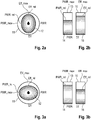
- FIG. 2a shows an operating situation in which the drive motor 2 is operated close to the maximum engine efficiency Eff_max, while the
- Motor power PWR is low. This is illustrated by a first geometric basic shape 11 in the form of a circle 11 and by a second substantially circular geometric basic shape 12. While the first basic shape 11 by their radial extent in the horizontal and vertical directions, the determined maximum values Eff_max and PWR_max for the engine efficiency and the Motor performance reflects the second basic form 12 by their radial extent in the horizontal and vertical directions, the relative values Eff_rel and PWR_rel for the engine efficiency and engine performance. While the radial distance between the relative value Eff_rel and the maximum value Eff_max for the motor efficiency in the vertical direction is small, the horizontal distance between the relative value PWR_rel and the maximum value PWR_max for the engine power points to the low available engine power PWR in this operating situation.
- the operator can easily make a picture of how the current setting of the working machine 1 has a simple effect based on the shape of the second basic shape 12 deviating from the first basic shape 11. Also, any geometric basic shapes deviating from the circular shape are conceivable in order to simplify the determined maximum values Eff_max and PWR_max for the engine efficiency and the engine power and in relation thereto the relative values Eff_rel and PWR_rel for the engine efficiency and the engine power in the manner described above.
- Fig. 2b show two bar graphs side by side, which are each visualized by two basic geometric shapes 13, 14 and 15, 16.
- the respective first basic form 13, 15 represents the maximum value PWR_max or Eff_max
- the respective second basic form 14, 16 represents the relative value PWR_rel or Eff_rel.
- the operator can also directly perceive the current engine power PWR and the engine efficiency Eff in relation to the possible maximum values PWR_max and Eff_max on the basis of the respective distance between the first basic shape 13, 15 and the superimposed second basic shape 14, 16 ,
- Fig. 3a is a second operational situation through a pie chart and in Fig. 3b is illustrated by a corresponding bar graph in which the adjustment of the drive motor 2 of the work machine allows operation with approximately maximum motor power PWR_max but reduced motor efficiency Eff. While the vertical extent of the second basic shape 12 for the relative value PWR_rel of the engine output is approximately equal to the diameter of the first basic shape 11, the distance between the second basic shape 12 is the relative value PWR_rel of the engine efficiency and the first basic shape 11 is the maximum value Eff_max of the engine efficiency relatively large.
- a third operating situation according to the first and second embodiments is illustrated, in which the setting of the drive motor 2 allows operation with a relative to the maximum motor power PWR_max relative value PWR_max of the engine power, while the motor efficiency Eff is low, which is due to the large distance between the Maximum value Eff_max and Eff_rel is clarified. This may be the case, for example, during operation of the work machine 1 at higher speeds or with an additional power decrease at the power take-off shaft 3.
- a fourth operating situation according to the first and second embodiment is illustrated, which represents an operation of the drive motor 2 in the Tellast Scheme.
- This operating situation is characterized by a low engine power PWR and a low engine efficiency Eff, as can be seen from the corresponding with the fourth operating situation pie or bar graphs.
- the representation of the engine power PWR is supplemented by a power limit PWR_Grenz, which serves to visually signal to the operator whether an operation of a working unit 10 connected to the power take-off shaft 3 at a reduced speed of the power take-off shaft 3 is possible at a reduced speed of the drive motor 2, whereby a low-consumption operation of the work machine 1 is made possible.
- a third and a fourth embodiment for the visualization of the relative values PWR_rel and Eff_rel are shown in conjunction with the determined maximum values Eff_max and PWR_max for the engine efficiency and the engine power.
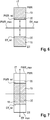
- the visualization takes place in a single combined graphical representation by visualizing a first basic shape 17 with two second basic shapes 18, 19, which are shown overlapping the first basic shape, by the display device 8.
- the second basic shapes 18, 19 have according to the in Fig. 6 illustrated third embodiment, a common target point, which is formed by the maximum values Eff_max and PWR_max, while the outer ends of the first basic form 17 form the respective origin.
- FIG Fig. 6 illustrated third embodiment a common target point, which is formed by the maximum values Eff_max and PWR_max, while the outer ends of the first basic form 17 form the respective origin.
- the second basic shapes 18, 19 have a common origin, while the outer ends of the first basic shape 17 represent the respective maximum values Eff_max and PWR_max. According to the respective embodiment, the respective second basic shape 18, 19 within the first basic shape 17 changes by expansion or contraction in the direction of the corresponding maximum value Eff_max or PWR_max or of the respective origin.
- FIG. 8 A fifth embodiment for the visualization of the relative values PWR_rel and Eff_rel is shown in conjunction with the maximum values Eff_max and PWR_max for the engine efficiency and the engine power.
- the presentation is based on an analogue pointer instrument.
- two basic geometric shapes 20, 21 and 22, 23 are provided, which essentially correspond to a circular ring segment and are shown overlapping one another.
- the respective first basic form 20, 22 gives the determined maximum values Eff_max and PWR_max for the engine efficiency and the engine power again.
- the respective second basic form 21, 23 illustrates the relative values Eff_rel and PWR_rel for the engine efficiency and the engine power by virtue of their proportional extent in the circumferential direction of the respective first basic form.
- Fig. 9 shows a very simplified sixth embodiment for the graphical visualization of the relative values PWR_rel and Eff_rel in conjunction with the maximum values Eff_max and PWR_max for the engine efficiency and the engine power.
- a coordinate system 24 is shown schematically in which the determined maximum values Eff_max and PWR_max are represented as a linear function 25.
- a value pair for the relative values Eff_rel and PWR_rel resulting from the current setting of the working machine 1 or the drive motor 2 is represented in the form of a point 26 in the coordinate system 24. From the location of the point 26 with respect to the course of the function 25, the operator can recognize the current setting of the drive motor 2 in relation to the engine efficiency Eff and the engine power PWR.
- the 10a and 10b show a seventh and eighth embodiment for visualizing the relative values PWR_rel and Eff_rel in conjunction with the maximum values Eff_max and PWR_max for the engine efficiency and the engine performance.
- pictorial symbols or icons 27a, 27b, 28a, 28b and 29 to 34 are used instead of basic geometric shapes in order to represent the relative values PWR_rel and Eff_rel in a comparative representation by the display device 8.
- pictorial analogies creates a very intuitive possibility of capturing the information presented. In contrast to the use of geometric basic forms, no abstract forms are presented, leaving room for further interpretation.
- Symbol 27a shows a small tree symbolizing a small relative value PWR_rel
- symbol 27b shows a large tree representing a large relative value PWR_rel
- the symbol 28b, a tree with leaves represents a large relative value Eff_rel.
- the eighth embodiment according to Fig. 10b shows a finer gradation between the respective relative values PWR_rel and Eff_rel through the use of a higher number of pictorial symbols 29, 30, 31 for the relative values PWR_rel and 32, 33, 34 relative values Eff_rel.
- a graphic picture element 36 is provided, which additionally illustrates the increasing profile of the relative values PWR_rel and Eff_rel.
- At least one additional visualization element 35 can be provided which, after a change in the setting of the drive motor 2, represents the previous relative values PWR_rel and Eff_rel. As a result, the operator understands the effect of a change made by her setting comprehensible.
Landscapes
- Engineering & Computer Science (AREA)
- Chemical & Material Sciences (AREA)
- Combustion & Propulsion (AREA)
- Transportation (AREA)
- Mechanical Engineering (AREA)
- Lifting Devices For Agricultural Implements (AREA)
Abstract
Description
- Die vorliegende Erfindung betrifft eine landwirtschaftliche Arbeitsmaschine, insbesondere einen Traktor, gemäß dem Oberbegriff des Anspruches 1.
- Für das Betreiben einer landwirtschaftlichen Arbeitsmaschine ist ein Antriebsstrang mit einem Antriebsmotor sowie einem Getriebe vorgesehen, welcher auch zum Antreiben zumindest eines Arbeitsaggregates zur Durchführung oder Unterstützung landwirtschaftlicher Arbeitsvorgänge oder Prozesse dient, welches Teil der landwirtschaftlichen Arbeitsmaschine oder mit dieser verbindbar und durch eine Nebenabtriebswelle des Getriebes antreibbar ist. Die landwirtschaftliche Arbeitsmaschine umfasst eine Steuereinheit zur Bestimmung von Betriebsparametern zumindest des Antriebsmotors und eine Anzeigevorrichtung zur Visualisierung der durch die Steuereinheit bestimmen Betriebsparameter. Die Visualisierung der Betriebsparameter dient dazu, einer Bedienperson einen Überblick über die aktuelle Betriebssituation zu geben sowie mögliche Verbesserungspotentiale der Leistungsfähigkeit der Arbeitsmaschine erkennen zu können.
- Aus der
DE 10 2013 110 610 A1 ist eine als Mähdrescher ausgebildete landwirtschaftliche Arbeitsmaschine mit einer Steuereinheit und einer Anzeigevorrichtung zur Anzeige von Parametern der Arbeitsmaschine bekannt, wobei die Steuereinheit eine Gesamteffizienz als einen Einzelwert generiert, welcher der Bedienperson angezeigt wird, wobei für die Bedienerperson aufgrund der Darstellung unmittelbar eine Identifikation eines leistungsbegrenzenden Arbeitsaggregates möglich ist. - Aus der
EP 2 734 026 A1 ist ein System zur Anzeige und Steuerung einer Arbeitsmaschine Traktors mit einem Anzeigeorgan zur Anzeige von Performance-Parametern für eine Bedienperson der Arbeitsmaschine bekannt. Das System umfasst einen Prozessor, der ein Simulationssystem bereitstellt, welcher dem Bediener das Ausprobieren unterschiedlicher Einstellungen ermöglicht. Aufgrund der Vielzahl an veränderbaren Parametern setzt das Nutzen des Systems bei der Bedienperson ein hohes Verständnis der technischen Zusammenhänge voraus, um zu sinnvollen Ergebnissen zu gelangen. Folglich ist dieses System nur in geringem Maße für eine einfache und anschauliche Optimierung der tatsächlichen Einstellungen der Arbeitsmaschine geeignet. - Nachteilig an dem vorgenannten Stand der Technik ist zudem, dass der Bedienperson ein unmittelbarer Zusammenhang zwischen einer Leistung und einem Wirkungsgrad des Antriebstranges nicht angezeigt wird, um der Bedienerperson das Einstellen eines optimalen Betriebspunktes für einen aktuellen Fahrzustand zu ermöglichen.
- Somit liegt der vorliegenden Erfindung die Aufgabe zugrunde, eine landwirtschaftliche Arbeitsmaschine der eingangs genannten Art bereitzustellen, welche einer Bedienperson den Zusammenhang der Betriebsparameter des Antriebsstranges, insbesondere zumindest des Antriebsmotors, auf schnell erfassbare und leicht verständliche Weise zugänglich werden lässt, um die Einstellungen der Arbeitsmaschine zu verbessern.
- Diese Ausgabe wird durch die Merkmale des unabhängigen Anspruches 1 gelöst.
- Vorteilhafte Weiterbildungen sind Gegenstand der Unteransprüche.
- Gemäß dem Anspruch 1 wird eine landwirtschaftliche Arbeitsmaschine, insbesondere Traktor, vorgeschlagen, mit einem Antriebsstrang, zumindest einen Antriebsmotor sowie ein Getriebe umfassend, zum Betreiben der Arbeitsmaschine und zum Antreiben zumindest eines Arbeitsaggregates zur Durchführung oder Unterstützung landwirtschaftlicher Arbeitsvorgänge oder Prozesse, sowie einer Steuereinheit zur Bestimmung von Betriebsparametern zumindest des Antriebsmotors und einer Anzeigevorrichtung zur Visualisierung der bestimmen Betriebsparameter. Um einer Bedienperson den Zusammenhang der Betriebsparameter des Antriebsstranges auf schnell erfassbare und leicht verständliche Weise zugänglich zu machen, um die Einstellungen der Arbeitsmaschine zur Erreichung eines höheren Wirkungsgrades und/oder einer höheren Leistung verbessern zu können, ist erfindungsgemäß vorgesehen, dass die Steuereinheit dazu eingerichtet ist, für einen aktuellen Betriebszustand der Arbeitsmaschine Werte für einen Wirkungsgrad und eine durch den Antriebsstrang übertragene Leistung zu ermitteln, durch Vergleich der ermittelten Werte mit hinterlegten und/oder generierten Maximalwerten des Wirkungsgrades und der Leistung jeweils einen aktuellen Relativwert des Wirkungsgrades und der Leistung zu generieren, und diese Relativwerte in vergleichender Darstellung durch die Anzeigevorrichtung darzustellen. Die vergleichende Darstellung der aktuellen Relativwerte des Wirkungsgrades und der Leistung mit den Maximalwerten des Wirkungsgrades und der Leistung des Antriebsstranges hat den Vorteil, dass bei einem Betrieb in Volllast und besonders im Teillastbereich des Antriebsmotors der Zusammenhang zwischen Leistung und Wirkungsgrad unmittelbar und leicht verständlich dargestellt wird. Einer Bedienperson der Arbeitsmaschine erschließt sich durch die vergleichende Darstellung einfacher der Zielkonflikt zwischen Wirkungsgrad und Leistung des Antriebsstranges und insbesondere des Antriebsmotors während des laufenden Betriebs der Arbeitsmaschine sowie der Einfluss des Betriebs der Arbeitsmaschine im niedrigen Teillastbereich auf den Motorwirkungsgrad. Insbesondere im Fall des Betriebs im niedrigen Teillastbereich, welcher sich ungünstig auf den Motorwirkungsgrad auswirkt, ist diese vereinfachte Visualisierung des Zielkonflikts bedeutsam, um die Arbeitsmaschine effizienter betreiben zu können.
- Bevorzugt kann die Steuereinheit dazu eingerichtet sein, für einen aktuellen Betriebszustand der Arbeitsmaschine Werte für einen Motorwirkungsgrad und eine durch den Antriebsmotor übertragene Motorleistung zu ermitteln und durch Vergleich der ermittelten Werte mit den Maximalwerten des Motorwirkungsgrades und der Motorleistung jeweils einen aktuellen Relativwert des Motorwirkungsgrades und der Motorleistung zu generieren.
- Dabei können die Maximalwerte des Wirkungsgrades und der Leistung in Abhängigkeit vom jeweiligen Antriebsstrang, insbesondere zumindest von dem Antriebsmotor, vorgebbar und in der Steuereinheit als Startwerte hinterlegbar sein. Denkbar ist auch eine Hinterlegung dieser Maximalwerte in Form eines Kennfeldes.
- Bevorzugt können die jeweils ermittelten Maximalwerte des Wirkungsgrades und der Leistung von der Steuereinheit abspeicherbar und als Vergleichswerte für die aktuellen Werte von Wirkungsgrad und Leistung zur Generierung der Relativwerte heranziehbar sein. Dies hat den Vorteil, dass so eine sehr genaue, motorspezifische Anzeige der Relativwerte ermöglicht werden kann.
- Gemäß einer Weiterbildung kann die Steuereinheit dazu eingerichtet sein, Wertebereiche, innerhalb derer eine Optimierung der Einstellung der Arbeitsmaschine möglich ist, zu bestimmen und in Verbindung mit dem jeweils aktuellen Relativwert des Wirkungsgrades und der Leistung darzustellen. Auf diese Weise kann der Bedienperson der Arbeitsmaschine eine einfache Orientierungshilfe gegeben werden, in welchem Umfang eine Optimierung des Betriebs der Arbeitsmaschine möglich ist. Die von der Steuereinheit bestimmten Wertebereiche können arbeitsvorgangsbezogen, z.B. Pflügen, Mähen, etc., oder unter Berücksichtigung von Umweltbedingungen, beispielsweise dem Arbeiten auf nassen Böden etc., in der Steuereinheit hinterlegbar sein.
- Insbesondere kann die Anzeige der Relativwerte des Wirkungsgrades und der Leistung abstrahiert durch eine kombinierte grafische Darstellung erfolgen. Die Bedienperson kann unmittelbar den Wirkungsgrad und die Leistung in Relation zu dem maximal möglichen Wirkungsgrad und der maximalen Leistung sehen und auf diese Weise den aktuellen Betriebspunkt zumindest des Antriebsmotors im Hinblick auf den Wirkungsgrad und die Leistung beurteilen.
- Hierbei kann die kombinierte grafische Darstellung mittels zumindest zweier im Wesentlichen gleicher geometrischer Grundformen erfolgen, wobei die zumindest zwei Grundformen von der Anzeigevorrichtung einander überlagernd darstellbar sind. Die Bedienperson kann aus der überlagerten Darstellung auf einen Blick abschätzen, mit welcher Leistung und welchem Wirkungsgrad in Relation zur maximalen Leistung und zum maximalen Wirkungsgrad des Antriebsstranges in dem aktuell eingestellten Betriebspunkt gearbeitet wird.
- Insbesondere kann die Darstellung der einen Grundform, welche die Maximalwerte des Wirkungsgrades und der Leistung wiedergibt, statisch erfolgen, während die Darstellung der anderen Grundform, welche die aktuellen Relativwerte des Wirkungsgrades und der Leistung wiedergibt, dynamisch erfolgt. Eine Anpassung der Einstellung zumindest des Antriebsmotors an wenigstens eine sich ändernde Betriebsbedingung, wie beispielsweise ein Wechsel des Arbeitsaggregates, oder das Verlassen des Teillastbereiches hin zum Betrieb unter Volllast, führt zu einer zeitnahen Aktualisierung der Darstellung. Insbesondere kann die überlagernde Darstellung in der Weise erfolgen, dass die dynamisch dargestellte Grundform die statisch dargestellte Grundform überlagert.
- Alternativ kann die Darstellung der Relativwerte des Wirkungsgrades und der Leistung abstrahiert unter Verwendung jeweils zumindest zweier im Wesentlichen gleicher geometrischer Grundformen erfolgen, wobei die Grundformen von der Anzeigevorrichtung einander gegenüberstellend darstellbar sind. Hierzu werden die Relativwerte und die Maximalwerte des Wirkungsgrades und der Leistung jeweils separiert voneinander mittels der beiden zugehörigen Grundformen durch die Anzeigevorrichtung angezeigt. Dabei ist eine Darstellung nebeneinander oder ineinander verschachtelt denkbar.
- Gemäß einer Weiterbildung kann die Steuereinheit dazu eingerichtet sein, einen Leistungsgrenzwert zu bestimmen und mittels der Anzeigevorrichtung abstrahiert darzustellen, welcher der Visualisierung der Möglichkeit des Betriebs des Antriebsmotors in einer ersten oder einer zweiten Betriebsart dient. Durch die Darstellung des Leistungsgrenzwertes kann der Bedienperson optisch signalisiert werden, ob beispielsweise ein Betrieb eines an der Nebenabtriebswelle angeschlossenen Arbeitsaggregates mit reduzierter Drehzahl der Nebenabtriebswelle bei einer zugleich abgesenkten Drehzahl des Antriebsmotors möglich ist, wodurch ein verbrauchsärmerer Betrieb der Arbeitsmaschine ermöglicht wird.
- Des Weiteren kann die Steuereinheit dazu eingerichtet sein, die Anzeigevorrichtung anzusteuern, um die aktuellen Relativwerte zusammen mit zumindest einem vorangehenden, in der Vergangenheit liegenden Relativwert des Wirkungsgrades und/oder der Leistung darzustellen. Hierzu kann zumindest ein Visualisierungselement vorgesehen sein, welches nach einer Änderung der Einstellung zumindest des Antriebsmotors die vorherigen Relativwerte des Wirkungsgrades und/oder der Leistung darstellt.
- Gemäß einer Weiterbildung kann die Steuereinheit dazu eingerichtet sein, die Anzeigevorrichtung anzusteuern, die Relativwerte des Wirkungsgrades und der Leistung in vergleichender Darstellung mittels Symbolen oder Piktogrammen durch bildhafte Analogien zu visualisieren. Die Verwendung bildhafter Analogien stellt eine sehr intuitive Möglichkeit dar, die dargestellten Informationen schnell und eindeutig zu erfassen. Im Unterschied zu der Verwendung von geometrischen Grundformen sind keine abstrakten Formen dargestellt, die einen Raum für eine weitergehende Interpretation lassen können.
- Die vorliegende Erfindung wird nachstehend anhand eines in den Zeichnungen dargestellten Ausführungsbeispieles näher erläutert.
- Es zeigen:
- Fig. 1
- eine schematische Ansicht einer landwirtschaftlichen Arbeitsmaschine;
- Fig. 2a, 2b
- eine erste und eine zweite Ausführungsform zur Visualisierung von Relativwerten in Zusammenschau mit ermittelten Maximalwerten für Motorwirkungsgrad und Motorleistung in einer ersten Betriebssituation der Arbeitsmaschine;
- Fig.3a, 3b
- die erste und zweite Ausführungsform zur Visualisierung von Relativwerten in einer zweiten Betriebssituation der Arbeitsmaschine;
- Fig.4a, 4b
- die erste und zweite Ausführungsform zur Visualisierung von Relativwerten in einer dritten Betriebssituation der Arbeitsmaschine;
- Fig.5a, 5b
- die erste und zweite Ausführungsform zur Visualisierung von Relativwerten in einer vierten Betriebssituation der Arbeitsmaschine;
- Fig. 6
- eine dritte Ausführungsform zur Visualisierung der Relativwerte in Zusammenschau mit den ermittelten Maximalwerten für den Motorwirkungsgrad und die Motorleistung;
- Fig. 7
- eine vierte Ausführungsformen zur Visualisierung der Relativwerte in Zusammenschau mit den ermittelten Maximalwerten für den Motorwirkungsgrad und die Motorleistung;
- Fig. 8
- eine fünfte Ausführungsform zur Visualisierung der Relativwerte in Zusammenschau mit den ermittelten Maximalwerten für den Motorwirkungsgrad und die Motorleistung;
- Fig. 9
- eine sechste Ausführungsform zur Visualisierung der Relativwerte in Zusammenschau mit den ermittelten Maximalwerten für den Motorwirkungsgrad und die Motorleistung; und
- Fig. 10a, 10b
- eine siebte und achte Ausführungsform zur Visualisierung der Relativwerte in Zusammenschau mit den ermittelten Maximalwerten für den Motorwirkungsgrad und die Motorleistung.
- In
Fig. 1 ist eine landwirtschaftliche Arbeitsmaschine 1, hier in Form eines Traktors, mit einem Antriebsstrang, der zumindest einen Antriebsmotor 2 und ein Getriebe 2a umfasst, zum Betreiben der Arbeitsmaschine 1 und zum Antreiben zumindest eines Arbeitsaggregates 10, bei dem es sich hier beispielhaft um einen Pflug handelt, zur Durchführung oder Unterstützung landwirtschaftlicher Prozesse, hier eine Bodenbearbeitung, dargestellt. Die landwirtschaftliche Arbeitsmaschine 1 weist eine Steuereinheit 4 auf, die mittels einer Erfassungseinrichtung 5, die verschiedene Sensoreinrichtungen 9 aufweist, unterschiedliche Betriebsparameter der Arbeitsmaschine 1 und/oder des Arbeitsaggregates 10 erfassen kann. Die Sensoreinrichtungen 5 können, um nur einige Beispiele zu nennen, dazu dienen, das abgegebene Antriebsdrehmoment des Antriebsmotors 2 der landwirtschaftlichen Arbeitsmaschine 1, die Drehzahl an der Antriebswelle des Antriebsmotors 2, eine oder mehrere Abtriebsdrehzahlen des Getriebes 2a, die Fahrgeschwindigkeit, die Drehzahl an einer Nebenabtriebswelle 3 des Getriebes 2a etc. zu erfassen. Neben einer automatischen Erfassung von Betriebsparametern mittels einer Sensoreinrichtung 9 ist es auch denkbar, Betriebsparameter durch Berechnung aus sensorisch erfassten Betriebsparametern, zum Beispiel die abgegebene Antriebsleistung aus Antriebsdrehmoment und Drehzahl, zu erhalten, wozu die Steuereinheit 4 eine Recheneinrichtung 6 umfasst, und/oder Betriebsparameter manuell einzugeben und/oder auszuwählen, wozu die Steuereinheit 4 insbesondere eine Anzeigevorrichtung 8, vorzugsweise in Form eines Touchscreens, aufweist. - Die Steuereinheit 4 der landwirtschaftlichen Arbeitsmaschine 1 weist ferner eine Datenbank 7 auf welche in der Recheneinrichtung 6 enthalten, in der die von einer Sensoreinrichtung 9 sowie der Recheneinrichtung 6 bestimmen Betriebsparameter abrufbar hinterlegt sind. Der Vollständigkeit halber sei darauf hingewiesen, dass die Recheneinrichtung 6 und/oder die Datenbank 7 genauso wie die Anzeigevorrichtung 8 nicht zwingend Bestandteil der landwirtschaftlichen Arbeitsmaschine 1 sein muss bzw. müssen, sondern alternativ oder zusätzlich auch außerhalb der Steuereinheit 4 und/oder der landwirtschaftlichen Arbeitsmaschine 1, das heißt extern, vorgesehen sein kann bzw. können.
- Die vorschlagsgemäße landwirtschaftliche Arbeitsmaschine 1 erlaubt mittels ihrer Steuereinheit 4 die Erfassung einer Vielzahl von Betriebsparametern und basierend auf den erfassten Betriebsparametern das Bilden unterschiedlicher Leistungskennzahlen des Antriebsstranges, welche die aktuelle Effizienz respektive einen aktuellen Wirkungsgrad in Relation zu einem maximalen Wirkungsgrad sowie eine aktuelle Leistung in Relation zu einer maximalen Leistung des Antriebsstranges wiedergeben. Bevorzugt werden von der Steuereinheit 4 zumindest Leistungskennzahlen des Antriebsmotors 2 gebildet, welche die aktuelle Effizienz respektive einen aktuellen Motorwirkungsgrad Eff in Relation zu einem maximalen Motorwirkungsgrad Eff_max sowie eine aktuelle Motorleistung PWR in Relation zu einer maximalen Motorleistung PWR_max wiedergeben.
- So kann beispielsweise die Visualisierung der Leistungskennzahlen auch auf einer separaten Anzeigeeinrichtung innerhalb einer Fahrerkabine der landwirtschaftlichen Arbeitsmaschine 1, auf einem mobilen Eingabe- und Anzeigegerät (smart device), auf einem externen Anzeigegerät eines Rechners des landwirtschaftlichen Betriebs oder eines Lohnunternehmers, auf einem externen Anzeigegerät einer anderen landwirtschaftlichen Arbeitsmaschine, auf einem externen Anzeigegerät eines Arbeitsaggregats 3 (zum Beispiel einer Ballenpresse) und/oder auf einem externen Anzeigegerät einer landwirtschaftlichen Einrichtung erfolgen. Die Recheneinrichtung 6 und/oder die Datenbank 7 kann bzw. können ebenfalls extern angeordnet sein, beispielsweise auf einem mobilen Eingabe- und Anzeigegerät oder auf einem externen Rechner des landwirtschaftlichen Betriebs oder eines Lohnunternehmers.
- Um einer Bedienperson der landwirtschaftlichen Arbeitsmaschine 1 den Zusammenhang zwischen der Antriebsleistung und dem Wirkungsgrad des Antriebsmotors 2 in einer leicht verständlichen und schnell erfassbaren Weise anzuzeigen, ist vorgesehen, dass die Steuereinheit 4 dazu eingerichtet ist, für einen aktuellen Betriebszustand der Arbeitsmaschine 1 Werte für den Motorwirkungsgrad Eff und die Motorleistung PWR zu ermitteln und durch Vergleich der ermittelten Werte mit hinterlegten und/oder generierten Maximalwerten des Motorwirkungsgrades Eff und der Motorleistung PWR jeweils einen aktuellen Relativwert des Motorwirkungsgrades Eff_rel und der Motorleistung PWR_rel zu generieren, und diese Relativwerte Eff_rel, PWR_rel in vergleichender Darstellung durch die Anzeigevorrichtung 8 darzustellen.
- Dies dient dazu, der Bedienperson das Optimieren des Betriebs der Arbeitsmaschine 1 durch eine geeignete Anpassung von Einstellungen zu erleichtern, indem die Zusammenhänge zwischen der Motorleistung PWR und dem Motorwirkungsgrad EFF möglichst anschaulich durch die Anzeigevorrichtung 8 visualisiert werden.
- Dazu können die Maximalwerte des Motorwirkungsgrades Eff_max und der Motorleistung PWR_max in Abhängigkeit vom jeweiligen Antriebsmotor 2 vorgebbar und in der Datenbank 7 der Steuereinheit 4 als Startwerte hinterlegbar sein. Denkbar ist auch eine Hinterlegung der Maximalwerte des Motorwirkungsgrades Eff_max und der Motorleistung PWR_max in Form eines Kennfeldes.
- Bevorzugt können die jeweils ermittelten Maximalwerte des Motorwirkungsgrades Eff_max und der Motorleistung PWR_max von der Steuereinheit 4 abspeicherbar und als Vergleichswerte für die aktuellen Werte von Motorwirkungsgrad Eff und Motorleistung PWR zur Generierung der Relativwerte Eff_rel und PWR_rel heranziehbar sein. Dies hat den Vorteil, dass so eine sehr genaue, motorspezifische Anzeige der Relativwerte Eff_rel und PWR_rel ermöglicht werden kann.
- Die Steuereinheit 4 ist dazu eingerichtet sein, Wertebereiche, innerhalb derer eine Optimierung der Einstellung der Arbeitsmaschine 1 möglich ist, zu bestimmen und in Verbindung mit dem jeweils aktuellen Relativwert dem Motorwirkungsgrad Eff_rel und der Motorleistung PWR_rel darzustellen. Auf diese Weise wird der Bedienperson der Arbeitsmaschine 1 eine einfache Orientierungshilfe gegeben, in welchem Umfang eine Optimierung des Betriebs der Arbeitsmaschine 1 möglich ist. Die von der Steuereinheit 4 bestimmten Wertebereiche lassen sich arbeitsvorgangsbezogen, z.B. für das Pflügen durch das Arbeitsgerät 10, oder unter Berücksichtigung von Umweltbedingungen, beispielsweise dem Arbeiten auf nassen Böden etc., in der Steuereinheit 4 abrufbar hinterlegen.
- Die Anzeige der durch die Recheneinrichtung generierten Relativwerte des Motorwirkungsgrades Eff_rel und der Motorleistung PWR_rel erfolgt abstrahiert durch eine kombinierte grafische Darstellung durch die Anzeigevorrichtung 8. Abstrahiert heißt in diesem Zusammenhang, dass die vergleichende Darstellung nicht in Form von Zahlen erfolgt, sondern die Bedienperson kann unmittelbar die Motorauslastung bzw. den Motorwirkungsgrad Eff und die Motorleistung PWR in Relation zu dem maximal möglichen Motorwirkungsgrad Eff_rel und der maximalen Motorleistung PWR_max sehen und auf diese Weise den aktuellen Betriebspunkt des Antriebsmotors 2 im Hinblick auf den Motorwirkungsgrad Eff und die Motorleistung PWR beurteilen.
- Hierfür ist die kombinierte grafische Darstellung unter Verwendung zumindest zweier im Wesentlichen gleicher geometrischer Grundformen 11, 12 bzw. 13, 14, 15, 16 vorgesehen, wobei die zumindest zwei Grundformen 11, 12 bzw. 13, 15, 14, 16 von der Anzeigevorrichtung 8 einander überlagernd darstellbar sind.
- So sind in den
Fig.2a bis Fig. 5b beispielhaft verschiedene Betriebssituationen der Arbeitsmaschine 1 dargestellt, welche jeweils in Form eines Kreisdiagramms - linke Abbildung - und eines Balkendiagramms - rechte Abbildung - mittels der Anzeigevorrichtung 8 dargestellt werden. - Die Darstellung in
Fig. 2a zeigt eine Betriebssituation, in welcher der Antriebsmotor 2 nahe am maximalen Motorwirkungsgrad Eff_max betrieben wird, während die - Motorleistung PWR gering ist. Veranschaulicht wird dies durch eine erste geometrische Grundform 11 in Form eines Kreises 11 und durch eine zweite im Wesentlichen kreisförmige geometrische Grundform 12. Während die erste Grundform 11 durch ihre radiale Ausdehnung in horizontaler und vertikaler Richtung die ermittelten Maximalwerte Eff_max und PWR_max für den Motorwirkungsgrad und die Motorleistung wiedergibt, veranschaulicht die zweite Grundform 12 durch ihre radiale Ausdehnung in horizontaler und vertikaler Richtung die Relativwerte Eff_rel und PWR_rel für den Motorwirkungsgrad und die Motorleistung. Während der radiale Abstand zwischen dem Relativwert Eff_rel und dem Maximalwert Eff_max für den Motorwirkungsgrad in vertikaler Richtung gering ist, weist der horizontale Abstand zwischen dem Relativwert PWR_rel und dem Maximalwert PWR_max für die Motorleistung auf die geringe zur Verfügung stehende Motorleistung PWR in dieser Betriebssituation hin. Die Bedienperson kann sich auf einfache Weise anhand der von der ersten Grundform 11 abweichenden Form der zweiten Grundform 12 unmittelbar ein Bild davon machen, wie sich die aktuelle Einstellung der Arbeitsmaschine 1 auswirkt. Es sind auch beliebige, von der Kreisform abweichende geometrische Grundformen denkbar, um die ermittelten Maximalwerte Eff_max und PWR_max für den Motorwirkungsgrad und die Motorleistung und in Relation hierzu die Relativwerte Eff_rel und PWR_rel für den Motorwirkungsgrad und die Motorleistung in der vorstehend beschriebenen Weise vereinfacht darzustellen.
- Die alternative Darstellung in
Fig. 2b zeigen zwei Balkendiagramme nebeneinander, welche jeweils durch zwei geometrische Grundformen 13, 14 und 15, 16 visualisiert werden. In analoger Weise zu dem Kreisdiagramm gibt die jeweilige erste Grundform 13, 15 den Maximalwert PWR_max bzw. Eff_max wieder, während die jeweilige zweite Grundform 14, 16 den Relativwert PWR_rel bzw. Eff_rel repräsentiert. Auch gemäß dieser alternativen Darstellung kann die Bedienperson anhand des jeweiligen Abstands zwischen der ersten Grundform 13, 15 und der von dieser überlagert dargestellten zweiten Grundform 14, 16 unmittelbar die aktuelle Motorleistung PWR und den Motorwirkungsgrad Eff in Relation zu den möglichen Maximalwerten PWR_max bzw. Eff_max wahrnehmen. Somit ist es der Bedienperson ohne weiteres möglich, die aktuelle Einstellung des Antriebsmotors 2 im Zusammenhang mit dem Motorwirkungsgrad Eff und der Motorleistung PWR zu beurteilen. - In
Fig. 3a ist eine zweite Betriebssituation durch ein Kreisdiagramm und inFig. 3b durch ein korrespondierendes Balkendiagramm veranschaulicht, in welcher die Einstellung des Antriebsmotors 2 der Arbeitsmaschine einen Betrieb mit annähernd maximaler Motorleistung PWR_max aber reduziertem Motorwirkungsgrad Eff ermöglicht. Während die Ausdehnung in vertikaler Richtung der zweiten Grundform 12 für den Relativwert PWR_rel der Motorleistung annähernd dem Durchmesser der ersten Grundform 11 entspricht, ist der Abstand zwischen der zweiten Grundform 12 für den Relativwert PWR_rel des Motorwirkungsgrades und der ersten Grundform 11 für den Maximalwert Eff_max des Motorwirkungsgrades relativ groß. - In
Fig. 4a und 4b ist jeweils eine dritte Betriebssituation gemäß der ersten und zweiten Ausführungsform veranschaulicht, in welcher die Einstellung des Antriebsmotors 2 einen Betrieb mit einem über der maximalen Motorleistung PWR_max liegenden Relativwert PWR_max der Motorleistung ermöglicht, während die Motoreffizienz Eff gering ist, was durch den großen Abstand zwischen dem Maximalwert Eff_max und Eff_rel verdeutlicht wird. Dies kann beispielsweise bei einem Betrieb der Arbeitsmaschine 1 mit höheren Geschwindigkeiten oder bei einer zusätzlichen Leistungsabnahme an der Nebenabtriebswelle 3 der Fall sein. - In
Fig. 5a und 5b ist jeweils eine vierte Betriebssituation gemäß der ersten und zweiten Ausführungsform veranschaulicht, welche einen Betrieb des Antriebsmotors 2 im Tellastbereich darstellt. Diese Betriebssituation zeichnet sich durch eine geringe Motorleistung PWR sowie einen geringen Motorwirkungsrad Eff aus, wie aus den mit der vierten Betriebssituation korrespondierenden Kreis- bzw. Balkendiagrammen zu entnehmen ist. Zusätzlich wird die Darstellung der Motorleistung PWR ergänzt durch einen Leistungsgrenzwert PWR_Grenz, welcher dazu dient, der Bedienperson optisch zu signalisieren, ob ein Betrieb eines an der Nebenabtriebswelle 3 angeschlossenen Arbeitsaggregates 10 mit reduzierter Drehzahl der Nebenabtriebswelle 3 bei einer abgesenkten Drehzahl des Antriebsmotors 2 möglich ist, wodurch ein verbrauchsärmerer Betrieb der Arbeitsmaschine 1 ermöglicht wird. - In den
Fig. 6 und 7 sind eine dritte und eine vierte Ausführungsform zur Visualisierung der Relativwerte PWR_rel und Eff_rel in Zusammenschau mit den ermittelten Maximalwerten Eff_max und PWR_max für den Motorwirkungsgrad und die Motorleistung gezeigt. Die Visualisierung erfolgt in einer einzelnen kombinierten grafischen Darstellung, indem eine erste Grundform 17 mit zwei die erste Grundform überlagernd dargestellten zweiten Grundformen 18, 19 von der Anzeigevorrichtung 8 visualisiert werden. Die zweiten Grundformen 18, 19 weisen gemäß der inFig. 6 dargestellten dritten Ausführungsform einen gemeinsamen Zielpunkt auf, der von den Maximalwerten Eff_max und PWR_max gebildet wird, während die äußeren Enden der ersten Grundform 17 den jeweiligen Ursprung bilden. Gemäß der Darstellung der vierten Ausführungsform inFig. 7 weisen die zweiten Grundformen 18, 19 einen gemeinsamen Ursprung auf, während die äußeren Enden der ersten Grundform 17 den jeweiligen Maximalwert Eff_max bzw. PWR_max darstellen. Entsprechend der jeweiligen Ausführungsform verändert sich die jeweilige zweite Grundform 18, 19 innerhalb der ersten Grundform 17 durch Ausdehnung oder Zusammenziehen in Richtung des entsprechenden Maximalwertes Eff_max bzw. PWR_max bzw. des jeweiligen Ursprungs. - In
Fig. 8 ist eine fünfte Ausführungsform zur Visualisierung der Relativwerte PWR_rel und Eff_rel in Zusammenschau mit den Maximalwerten Eff_max und PWR_max für den Motorwirkungsgrad und die Motorleistung gezeigt. Die Darstellung erfolgt in Anlehnung an ein analoges Zeigerinstrument. Zur Visualisierung sind wiederum jeweils zwei geometrische Grundformen 20, 21 und 22, 23 vorgesehen, die im Wesentlichen einem Kreisringsegment entsprechen und einander überlagernd dargestellt werden. Die jeweilige erste Grundform 20, 22 gibt die ermittelten Maximalwerte Eff_max und PWR_max für den Motorwirkungsgrad und die Motorleistung wieder. Die jeweilige zweite Grundform 21, 23 veranschaulicht durch ihre anteilige Ausdehnung in Umfangsrichtung der jeweiligen ersten Grundform die Relativwerte Eff_rel und PWR_rel für den Motorwirkungsgrad und die Motorleistung. -
Fig. 9 zeigt eine sehr vereinfachte sechste Ausführungsform zur grafischen Visualisierung der Relativwerte PWR_rel und Eff_rel in Zusammenschau mit den Maximalwerten Eff_max und PWR_max für den Motorwirkungsgrad und die Motorleistung. Dazu wird ein Koordinatensystem 24 schematisch dargestellt, in der die ermittelten Maximalwerte Eff_max und PWR_max als eine lineare Funktion 25 dargestellt sind. Ein sich aus der aktuellen Einstellung der Arbeitsmaschine 1 respektive des Antriebsmotors 2 ergebendes Wertepaar für die Relativwerte Eff_rel und PWR_rel wird in Form eines Punktes 26 in dem Koordinatensystem 24 dargestellt. Aus der Lage des Punktes 26 in Bezug auf den Verlauf der Funktion 25 kann die Bedienperson erkennen, die aktuelle Einstellung des Antriebsmotors 2 im Zusammenhang mit dem Motorwirkungsgrad Eff und der Motorleistung PWR beurteilen. - Die
Fig. 10a und 10b zeigen eine siebte und achte Ausführungsform zur Visualisierung der Relativwerte PWR_rel und Eff_rel in Zusammenschau mit den Maximalwerten Eff_max und PWR_max für den Motorwirkungsgrad und die Motorleistung. Hierbei werden anstelle von geometrischen Grundformen bildhafte Symbole bzw. Piktogramme 27a, 27b, 28a, 28b, bzw. 29 bis 34 verwendet, um die Relativwerte PWR_rel und Eff_rel in vergleichender Darstellung durch die Anzeigevorrichtung 8 darzustellen. Durch die Verwendung bildhafter Analogien wird eine sehr intuitive Möglichkeit geschaffen, die dargestellten Informationen zu erfassen. Im Unterschied zu der Verwendung von geometrischen Grundformen sind keine abstrakten Formen dargestellt, die einen Raum für eine weitergehende Interpretation lassen. Symbol 27a zeigt einen kleinen Baum, was einen kleinen Relativwert PWR_rel symbolisiert, während Symbol 27b einen groß gewachsenen Baum zeigt, der für einen großen Relativwert PWR_rel steht. In entsprechender Weise veranschaulicht das als Baum ohne Blätter dargestellte Symbol 28a einen kleinen Relativwert Eff_rel, während das Symbol 28b, ein Baum mit Blättern, einen großen Relativwert Eff_rel darstellt. - Die achte Ausführungsform gemäß
Fig. 10b zeigt eine feinere Abstufung zwischen den jeweiligen Relativwerten PWR_rel und Eff_rel durch die Verwendung einer höheren Anzahl von bildhaften Symbolen 29, 30, 31 für die Relativwerte PWR_rel und 32, 33, 34 Relativwerten Eff_rel. Zusätzlich ist unterhalb der Symbole gemäß der siebten und achten Ausführungsform ein grafisches Bildelement 36 vorgesehen, welches den ansteigenden Verlauf der Relativwerte PWR_rel und Eff_rel zusätzlich verdeutlicht. - Bei den vorstehend beschriebenen Ausführungsformen kann zumindest ein zusätzliches Visualisierungselement 35 vorgesehen sein, welches nach einer Änderung der Einstellung des Antriebsmotors 2 die vorherigen Relativwerte PWR_rel und Eff_rel darstellt. Dadurch wird der Bedienperson die Auswirkung einer von ihr vorgenommenen Einstellungsänderung nachvollziehbar verdeutlicht.
Bezugszeichenliste 1 Arbeitsmaschine 29 Symbol 2 Antriebsmotor 30 Symbol 3 Nebenabtriebswelle 31 Symbol 4 Steuereinheit 32 Symbol 5 Erfassungseinrichtung 33 Symbol 6 Recheneinrichtung 34 Symbol 7 Datenbank 35 Visualisierungselement 8 Anzeigevorrichtung 36 Bildelement 9 Sensoreinrichtung PWR Motorleistung 10 Arbeitsgerät PWR_max Maximalwert Motorleistung 11 Geometrische Grundform PWR_rel Relativwert Motorleistung 12 Geometrische Grundform PWR_Grenz Leistungsgrenzwert 13 Geometrische Grundform Eff Motorwirkungsgrad 14 Geometrische Grundform Eff_max Maximalwert Motorwirkungsgrad 15 Geometrische Grundform Eff_rel Relativwert Motorwirkungsgrad 16 Geometrische Grundform 17 Geometrische Grundform 18 Geometrische Grundform 19 Geometrische Grundform 20 Geometrische Grundform 21 Geometrische Grundform 22 Geometrische Grundform 23 Geometrische Grundform 24 Koordinatensystem 25 Funktion 26 Wertepaar 27a Symbol 27b Symbol 28a Symbol 28b Symbol
Claims (12)
- Landwirtschaftliche Arbeitsmaschine (1), insbesondere Traktor, mit einem Antriebsstrang, zumindest einen Antriebsmotor (2) sowie ein Getriebe (2a) umfassend, zum Betreiben der Arbeitsmaschine (1) und zum Antreiben zumindest eines Arbeitsaggregates (10) zur Durchführung oder Unterstützung landwirtschaftlicher Arbeitsvorgänge oder Prozesse, sowie einer Steuereinheit (4) zur Bestimmung von Betriebsparametern zumindest des Antriebsmotors (2) und einer Anzeigevorrichtung (8) zur Visualisierung der bestimmen Betriebsparameter, dadurch gekennzeichnet, dass die Steuereinheit (4) dazu eingerichtet ist, für einen aktuellen Betriebszustand der Arbeitsmaschine (1) Werte für einen Wirkungsgrad (Eff) und eine durch den Antriebsstrang übertragene Leistung (PWR) zu ermitteln, durch Vergleich der ermittelten Werte mit hinterlegten und/oder generierten Maximalwerten des Wirkungsgrades (Eff_max) und der Leistung (PWR_max) jeweils einen aktuellen Relativwert des Wirkungsgrades (Eff_rel) und der Leistung (PWR_rel) zu generieren, und diese Relativwerte (Eff_rel, PWR_rel) in vergleichender Darstellung durch die Anzeigevorrichtung (8) darzustellen.
- Landwirtschaftliche Arbeitsmaschine (1) nach Anspruch 1, dadurch gekennzeichnet, dass die Steuereinheit (4) dazu eingerichtet sein, für einen aktuellen Betriebszustand der Arbeitsmaschine (1) Werte für einen Motorwirkungsgrad (Eff) und eine durch den Antriebsmotor (2) übertragene Motorleistung (PWR) zu ermitteln und durch Vergleich der ermittelten Werte mit den Maximalwerten des Motorwirkungsgrades (Eff_max) und der Motorleistung (PWR_max) jeweils einen aktuellen Relativwert des Motorwirkungsgrades (Eff_rel) und der Motorleistung (PWR_rel) zu generieren.
- Landwirtschaftliche Arbeitsmaschine (1) nach Anspruch 1 oder 2, dadurch gekennzeichnet, dass die Maximalwerte des Wirkungsgrades (Eff_max) und der Leistung (PWR_max) in Abhängigkeit vom jeweiligen Antriebsmotor (2) und/oder Getriebe (2a) vorgebbar und in der Steuereinheit (4) als Startwerte hinterlegbar sind.
- Landwirtschaftliche Arbeitsmaschine (1) nach einem der Ansprüche 1 bis 3, dadurch gekennzeichnet, dass die jeweils ermittelten Maximalwerte des Wirkungsgrades (Eff_max) und der Leistung (PWR_max) von der Steuereinheit (4) abspeicherbar und als Vergleichswerte für die aktuellen Werte von Wirkungsgrad (Eff) und Leistung (PWR) zur Generierung der Relativwerte (Eff_rel, PWR_rel heranziehbar sind.
- Landwirtschaftliche Arbeitsmaschine (1) nach einem der vorangehenden Ansprüche, dadurch gekennzeichnet, dass die Steuereinheit (4) dazu eingerichtet ist, Wertebereiche, innerhalb derer eine Optimierung der Einstellung der Arbeitsmaschine (1) möglich ist, zu bestimmen und in Verbindung mit dem jeweils aktuellen Relativwert des Wirkungsgrades (Eff_rel) und der Leistung (PWR_rel) darzustellen.
- Landwirtschaftliche Arbeitsmaschine (1) nach einem der vorangehenden Ansprüche, dadurch gekennzeichnet, dass die Anzeige der Relativwerte des Wirkungsgrades (Eff_rel) und der Leistung (PWR_rel) abstrahiert durch eine kombinierte grafische Darstellung erfolgt.
- Landwirtschaftliche Arbeitsmaschine (1) nach Anspruch 6, dadurch gekennzeichnet, dass die kombinierte grafische Darstellung unter Verwendung zumindest zweier im Wesentlichen gleicher geometrischer Grundformen (11, 12) erfolgt, wobei die zumindest zwei Grundformen (11, 12) von der Anzeigevorrichtung (8) einander überlagernd darstellbar sind.
- Landwirtschaftliche Arbeitsmaschine (1) nach Anspruch 7, dadurch gekennzeichnet, dass die Darstellung der einen Grundform (11), welche die Maximalwerte des Wirkungsgrades (Eff_max) und der Motorleistung (PWR_max) wiedergibt, statisch erfolgt, während die Darstellung der anderen Grundform (12), welche die aktuellen Relativwerte des Wirkungsgrades (Eff_rel) und der Leistung (PWR_rel) wiedergibt, dynamisch erfolgt.
- Landwirtschaftliche Arbeitsmaschine (1) nach einem der Ansprüche 1 bis 6, dadurch gekennzeichnet, dass die Darstellung der Relativwerte des Wirkungsgrades (Eff_rel) und der Leistung (PWR_rel) abstrahiert unter Verwendung jeweils zumindest zweier im Wesentlichen gleicher geometrischer Grundformen (13, 14 und 15, 16) erfolgt, wobei die Grundformen (13, 14 und 15, 16) von der Anzeigevorrichtung (8) einander gegenüberstellend darstellbar sind.
- Landwirtschaftliche Arbeitsmaschine (1) nach einem der vorangehenden Ansprüche, dadurch gekennzeichnet, dass die Steuereinheit (4) dazu eingerichtet sein, einen Leistungsgrenzwert (PWR_Grenz) zu bestimmen und mittels der Anzeigevorrichtung (8) abstrahiert darzustellen, welcher der Visualisierung der Möglichkeit des Betriebs des Antriebsmotors (2) in einer ersten oder einer zweiten Betriebsart dient.
- Landwirtschaftliche Arbeitsmaschine (1) nach einem der vorangehenden Ansprüche, dadurch gekennzeichnet, dass die Steuereinheit (4) dazu eingerichtet ist, die Anzeigevorrichtung (8) anzusteuern, um die aktuellen Relativwerte (Eff_rel, PWR_rel) zusammen mit zumindest einem vorangehenden, in der Vergangenheit liegenden Relativwert des Wirkungsgrades und/oder der Leistung darzustellen.
- Landwirtschaftliche Arbeitsmaschine (1) nach einem der vorangehenden Ansprüche, dadurch gekennzeichnet, dass die Steuereinheit (1) dazu eingerichtet ist, die Anzeigevorrichtung (8) anzusteuern, die Relativwerte (EFF_rel, PWR_rel) in vergleichender Darstellung mittels Symbolen (27a, 27a, 28a, 28b; 29 -34) oder Piktogrammen durch bildhafte Analogien zu visualisieren.
Applications Claiming Priority (1)
| Application Number | Priority Date | Filing Date | Title |
|---|---|---|---|
| DE102018107577.4A DE102018107577A1 (de) | 2018-03-29 | 2018-03-29 | Landwirtschaftliche Arbeitsmaschine |
Publications (2)
| Publication Number | Publication Date |
|---|---|
| EP3549808A1 true EP3549808A1 (de) | 2019-10-09 |
| EP3549808B1 EP3549808B1 (de) | 2022-06-01 |
Family
ID=65030945
Family Applications (1)
| Application Number | Title | Priority Date | Filing Date |
|---|---|---|---|
| EP19151767.1A Active EP3549808B1 (de) | 2018-03-29 | 2019-01-15 | Landwirtschaftliche arbeitsmaschine |
Country Status (2)
| Country | Link |
|---|---|
| EP (1) | EP3549808B1 (de) |
| DE (1) | DE102018107577A1 (de) |
Citations (4)
| Publication number | Priority date | Publication date | Assignee | Title |
|---|---|---|---|---|
| EP2734026A1 (de) | 2011-07-22 | 2014-05-28 | AGCO International GmbH | Steuerungs-/anzeigesysteme für einen traktor |
| EP2734027A1 (de) * | 2011-07-22 | 2014-05-28 | AGCO International GmbH | Steuersystem für einen traktor |
| US20140378274A1 (en) * | 2010-01-21 | 2014-12-25 | Kubota Corporation | Speed Change System for Work Vehicle |
| DE102013110610A1 (de) | 2013-09-26 | 2015-03-26 | Claas Selbstfahrende Erntemaschinen Gmbh | Landwirtschaftliche Arbeitsmaschine mit einer Anzeigevorrichtung |
-
2018
- 2018-03-29 DE DE102018107577.4A patent/DE102018107577A1/de not_active Withdrawn
-
2019
- 2019-01-15 EP EP19151767.1A patent/EP3549808B1/de active Active
Patent Citations (4)
| Publication number | Priority date | Publication date | Assignee | Title |
|---|---|---|---|---|
| US20140378274A1 (en) * | 2010-01-21 | 2014-12-25 | Kubota Corporation | Speed Change System for Work Vehicle |
| EP2734026A1 (de) | 2011-07-22 | 2014-05-28 | AGCO International GmbH | Steuerungs-/anzeigesysteme für einen traktor |
| EP2734027A1 (de) * | 2011-07-22 | 2014-05-28 | AGCO International GmbH | Steuersystem für einen traktor |
| DE102013110610A1 (de) | 2013-09-26 | 2015-03-26 | Claas Selbstfahrende Erntemaschinen Gmbh | Landwirtschaftliche Arbeitsmaschine mit einer Anzeigevorrichtung |
Also Published As
| Publication number | Publication date |
|---|---|
| EP3549808B1 (de) | 2022-06-01 |
| DE102018107577A1 (de) | 2019-10-02 |
Similar Documents
| Publication | Publication Date | Title |
|---|---|---|
| EP3300978B1 (de) | Landwirtschaftliche arbeitsmaschine | |
| DE102009011015B4 (de) | Verfahren zur Anzeige einer Restreichweite eines Kraftfahrzeugs | |
| WO2012059162A2 (de) | Verfahren und vorrichtung zum anzeigen von werten in einem fahrzeug | |
| EP3139235B1 (de) | Verfahren zum betreiben von landwirtschaftlichen arbeitsmaschinen | |
| EP2215408B1 (de) | Kochfeld mit einer hausgerätanzeigevorrichtung | |
| EP3434087B1 (de) | Verfahren zum unterstützen eines maschinenbedieners beim einstellen einer landwirtschaftlichen bodenbearbeitungsmaschine | |
| DE102013011688A1 (de) | Datenanzeigevorrichtung für Maschinenwerkzeuge zur Anzeige von Daten aufgrund vorgegebener Zustände | |
| EP3276579A1 (de) | Verfahren und system zur bestimmung eines belastungszustandes eines, insbesondere landwirtschaftlichen, fahrzeuges | |
| DE102013221757B4 (de) | Einrichtung und Verfahren zur Analyse und/oder Dokumentation des Betriebs eines Arbeitsfahrzeugs | |
| DE4239530C2 (de) | Variabler Zapfwellenantrieb | |
| EP3549808B1 (de) | Landwirtschaftliche arbeitsmaschine | |
| DE10112008A1 (de) | Bildverarbeitungsvorrichtung und computerlesbares Speichermedium | |
| EP3354509B1 (de) | Anzeigevorrichtung zur darstellung einer aktuellen drehzahl eines kraftfahrzeugs | |
| EP4133925B1 (de) | Verfahren für den betrieb eines landwirtschaftlichen gespanns | |
| EP3783842A1 (de) | System und verfahren zur datenkommunikation innerhalb landwirtschaftlicher arbeitsmaschinen oder arbeitskombinationen | |
| EP4018276B1 (de) | Erweiterte trendanzeige von prozessdaten und sekundäralarmen | |
| EP2803254A1 (de) | Kontrollsystem für Anbaugeräte einer landwirtschaftlichen Arbeitsmaschine | |
| EP2686769B1 (de) | Anzeigevorrichtung mit schrittmotor und watchdogtimer | |
| EP4103364A1 (de) | Graphisch unterstützte anpassung von roboter-steuerprogrammen | |
| EP1937504B1 (de) | Landwirtschaftliches mobilfahrzeug | |
| EP3906764A1 (de) | Landwirtschaftliches assistenzsystem | |
| EP4000374B1 (de) | System zur anzeige von anzeigeobjekten | |
| EP4331344B1 (de) | Verfahren zum bestimmen eines verschleisszustands einer selbstfahrenden landwirtschaftlichen erntemaschine | |
| EP4075367A1 (de) | Computersystem zur verbindung mit einer landwirtschaftlichen arbeitsmaschine | |
| EP3732950B1 (de) | Verfahren für den betrieb einer selbstfahrenden landwirtschaftlichen arbeitsmaschine |
Legal Events
| Date | Code | Title | Description |
|---|---|---|---|
| PUAI | Public reference made under article 153(3) epc to a published international application that has entered the european phase |
Free format text: ORIGINAL CODE: 0009012 |
|
| STAA | Information on the status of an ep patent application or granted ep patent |
Free format text: STATUS: THE APPLICATION HAS BEEN PUBLISHED |
|
| AK | Designated contracting states |
Kind code of ref document: A1 Designated state(s): AL AT BE BG CH CY CZ DE DK EE ES FI FR GB GR HR HU IE IS IT LI LT LU LV MC MK MT NL NO PL PT RO RS SE SI SK SM TR |
|
| AX | Request for extension of the european patent |
Extension state: BA ME |
|
| STAA | Information on the status of an ep patent application or granted ep patent |
Free format text: STATUS: REQUEST FOR EXAMINATION WAS MADE |
|
| 17P | Request for examination filed |
Effective date: 20200409 |
|
| RBV | Designated contracting states (corrected) |
Designated state(s): AL AT BE BG CH CY CZ DE DK EE ES FI FR GB GR HR HU IE IS IT LI LT LU LV MC MK MT NL NO PL PT RO RS SE SI SK SM TR |
|
| GRAP | Despatch of communication of intention to grant a patent |
Free format text: ORIGINAL CODE: EPIDOSNIGR1 |
|
| STAA | Information on the status of an ep patent application or granted ep patent |
Free format text: STATUS: GRANT OF PATENT IS INTENDED |
|
| RIC1 | Information provided on ipc code assigned before grant |
Ipc: B62D 49/00 20060101ALI20211126BHEP Ipc: B60K 37/06 20060101AFI20211126BHEP |
|
| INTG | Intention to grant announced |
Effective date: 20211223 |
|
| GRAS | Grant fee paid |
Free format text: ORIGINAL CODE: EPIDOSNIGR3 |
|
| GRAA | (expected) grant |
Free format text: ORIGINAL CODE: 0009210 |
|
| STAA | Information on the status of an ep patent application or granted ep patent |
Free format text: STATUS: THE PATENT HAS BEEN GRANTED |
|
| AK | Designated contracting states |
Kind code of ref document: B1 Designated state(s): AL AT BE BG CH CY CZ DE DK EE ES FI FR GB GR HR HU IE IS IT LI LT LU LV MC MK MT NL NO PL PT RO RS SE SI SK SM TR |
|
| REG | Reference to a national code |
Ref country code: GB Ref legal event code: FG4D Free format text: NOT ENGLISH |
|
| REG | Reference to a national code |
Ref country code: AT Ref legal event code: REF Ref document number: 1495174 Country of ref document: AT Kind code of ref document: T Effective date: 20220615 Ref country code: CH Ref legal event code: EP Ref country code: DE Ref legal event code: R096 Ref document number: 502019004474 Country of ref document: DE |
|
| REG | Reference to a national code |
Ref country code: IE Ref legal event code: FG4D Free format text: LANGUAGE OF EP DOCUMENT: GERMAN |
|
| REG | Reference to a national code |
Ref country code: LT Ref legal event code: MG9D |
|
| REG | Reference to a national code |
Ref country code: NL Ref legal event code: MP Effective date: 20220601 |
|
| PG25 | Lapsed in a contracting state [announced via postgrant information from national office to epo] |
Ref country code: SE Free format text: LAPSE BECAUSE OF FAILURE TO SUBMIT A TRANSLATION OF THE DESCRIPTION OR TO PAY THE FEE WITHIN THE PRESCRIBED TIME-LIMIT Effective date: 20220601 Ref country code: NO Free format text: LAPSE BECAUSE OF FAILURE TO SUBMIT A TRANSLATION OF THE DESCRIPTION OR TO PAY THE FEE WITHIN THE PRESCRIBED TIME-LIMIT Effective date: 20220901 Ref country code: LT Free format text: LAPSE BECAUSE OF FAILURE TO SUBMIT A TRANSLATION OF THE DESCRIPTION OR TO PAY THE FEE WITHIN THE PRESCRIBED TIME-LIMIT Effective date: 20220601 Ref country code: HR Free format text: LAPSE BECAUSE OF FAILURE TO SUBMIT A TRANSLATION OF THE DESCRIPTION OR TO PAY THE FEE WITHIN THE PRESCRIBED TIME-LIMIT Effective date: 20220601 Ref country code: GR Free format text: LAPSE BECAUSE OF FAILURE TO SUBMIT A TRANSLATION OF THE DESCRIPTION OR TO PAY THE FEE WITHIN THE PRESCRIBED TIME-LIMIT Effective date: 20220902 Ref country code: FI Free format text: LAPSE BECAUSE OF FAILURE TO SUBMIT A TRANSLATION OF THE DESCRIPTION OR TO PAY THE FEE WITHIN THE PRESCRIBED TIME-LIMIT Effective date: 20220601 Ref country code: ES Free format text: LAPSE BECAUSE OF FAILURE TO SUBMIT A TRANSLATION OF THE DESCRIPTION OR TO PAY THE FEE WITHIN THE PRESCRIBED TIME-LIMIT Effective date: 20220601 Ref country code: BG Free format text: LAPSE BECAUSE OF FAILURE TO SUBMIT A TRANSLATION OF THE DESCRIPTION OR TO PAY THE FEE WITHIN THE PRESCRIBED TIME-LIMIT Effective date: 20220901 |
|
| PG25 | Lapsed in a contracting state [announced via postgrant information from national office to epo] |
Ref country code: RS Free format text: LAPSE BECAUSE OF FAILURE TO SUBMIT A TRANSLATION OF THE DESCRIPTION OR TO PAY THE FEE WITHIN THE PRESCRIBED TIME-LIMIT Effective date: 20220601 Ref country code: PL Free format text: LAPSE BECAUSE OF FAILURE TO SUBMIT A TRANSLATION OF THE DESCRIPTION OR TO PAY THE FEE WITHIN THE PRESCRIBED TIME-LIMIT Effective date: 20220601 Ref country code: LV Free format text: LAPSE BECAUSE OF FAILURE TO SUBMIT A TRANSLATION OF THE DESCRIPTION OR TO PAY THE FEE WITHIN THE PRESCRIBED TIME-LIMIT Effective date: 20220601 |
|
| PG25 | Lapsed in a contracting state [announced via postgrant information from national office to epo] |
Ref country code: NL Free format text: LAPSE BECAUSE OF FAILURE TO SUBMIT A TRANSLATION OF THE DESCRIPTION OR TO PAY THE FEE WITHIN THE PRESCRIBED TIME-LIMIT Effective date: 20220601 |
|
| PG25 | Lapsed in a contracting state [announced via postgrant information from national office to epo] |
Ref country code: SM Free format text: LAPSE BECAUSE OF FAILURE TO SUBMIT A TRANSLATION OF THE DESCRIPTION OR TO PAY THE FEE WITHIN THE PRESCRIBED TIME-LIMIT Effective date: 20220601 Ref country code: SK Free format text: LAPSE BECAUSE OF FAILURE TO SUBMIT A TRANSLATION OF THE DESCRIPTION OR TO PAY THE FEE WITHIN THE PRESCRIBED TIME-LIMIT Effective date: 20220601 Ref country code: RO Free format text: LAPSE BECAUSE OF FAILURE TO SUBMIT A TRANSLATION OF THE DESCRIPTION OR TO PAY THE FEE WITHIN THE PRESCRIBED TIME-LIMIT Effective date: 20220601 Ref country code: PT Free format text: LAPSE BECAUSE OF FAILURE TO SUBMIT A TRANSLATION OF THE DESCRIPTION OR TO PAY THE FEE WITHIN THE PRESCRIBED TIME-LIMIT Effective date: 20221003 Ref country code: EE Free format text: LAPSE BECAUSE OF FAILURE TO SUBMIT A TRANSLATION OF THE DESCRIPTION OR TO PAY THE FEE WITHIN THE PRESCRIBED TIME-LIMIT Effective date: 20220601 Ref country code: CZ Free format text: LAPSE BECAUSE OF FAILURE TO SUBMIT A TRANSLATION OF THE DESCRIPTION OR TO PAY THE FEE WITHIN THE PRESCRIBED TIME-LIMIT Effective date: 20220601 |
|
| PG25 | Lapsed in a contracting state [announced via postgrant information from national office to epo] |
Ref country code: IS Free format text: LAPSE BECAUSE OF FAILURE TO SUBMIT A TRANSLATION OF THE DESCRIPTION OR TO PAY THE FEE WITHIN THE PRESCRIBED TIME-LIMIT Effective date: 20221001 |
|
| REG | Reference to a national code |
Ref country code: DE Ref legal event code: R097 Ref document number: 502019004474 Country of ref document: DE |
|
| PG25 | Lapsed in a contracting state [announced via postgrant information from national office to epo] |
Ref country code: AL Free format text: LAPSE BECAUSE OF FAILURE TO SUBMIT A TRANSLATION OF THE DESCRIPTION OR TO PAY THE FEE WITHIN THE PRESCRIBED TIME-LIMIT Effective date: 20220601 |
|
| PLBE | No opposition filed within time limit |
Free format text: ORIGINAL CODE: 0009261 |
|
| STAA | Information on the status of an ep patent application or granted ep patent |
Free format text: STATUS: NO OPPOSITION FILED WITHIN TIME LIMIT |
|
| PG25 | Lapsed in a contracting state [announced via postgrant information from national office to epo] |
Ref country code: DK Free format text: LAPSE BECAUSE OF FAILURE TO SUBMIT A TRANSLATION OF THE DESCRIPTION OR TO PAY THE FEE WITHIN THE PRESCRIBED TIME-LIMIT Effective date: 20220601 |
|
| 26N | No opposition filed |
Effective date: 20230302 |
|
| PG25 | Lapsed in a contracting state [announced via postgrant information from national office to epo] |
Ref country code: SI Free format text: LAPSE BECAUSE OF FAILURE TO SUBMIT A TRANSLATION OF THE DESCRIPTION OR TO PAY THE FEE WITHIN THE PRESCRIBED TIME-LIMIT Effective date: 20220601 |
|
| P01 | Opt-out of the competence of the unified patent court (upc) registered |
Effective date: 20230516 |
|
| REG | Reference to a national code |
Ref country code: CH Ref legal event code: PL |
|
| GBPC | Gb: european patent ceased through non-payment of renewal fee |
Effective date: 20230115 |
|
| PG25 | Lapsed in a contracting state [announced via postgrant information from national office to epo] |
Ref country code: LU Free format text: LAPSE BECAUSE OF NON-PAYMENT OF DUE FEES Effective date: 20230115 |
|
| REG | Reference to a national code |
Ref country code: BE Ref legal event code: MM Effective date: 20230131 |
|
| PG25 | Lapsed in a contracting state [announced via postgrant information from national office to epo] |
Ref country code: LI Free format text: LAPSE BECAUSE OF NON-PAYMENT OF DUE FEES Effective date: 20230131 Ref country code: GB Free format text: LAPSE BECAUSE OF NON-PAYMENT OF DUE FEES Effective date: 20230115 Ref country code: CH Free format text: LAPSE BECAUSE OF NON-PAYMENT OF DUE FEES Effective date: 20230131 |
|
| REG | Reference to a national code |
Ref country code: DE Ref legal event code: R079 Ref document number: 502019004474 Country of ref document: DE Free format text: PREVIOUS MAIN CLASS: B60K0037060000 Ipc: B60K0035100000 |
|
| PG25 | Lapsed in a contracting state [announced via postgrant information from national office to epo] |
Ref country code: BE Free format text: LAPSE BECAUSE OF NON-PAYMENT OF DUE FEES Effective date: 20230131 |
|
| PG25 | Lapsed in a contracting state [announced via postgrant information from national office to epo] |
Ref country code: IT Free format text: LAPSE BECAUSE OF FAILURE TO SUBMIT A TRANSLATION OF THE DESCRIPTION OR TO PAY THE FEE WITHIN THE PRESCRIBED TIME-LIMIT Effective date: 20220601 Ref country code: IE Free format text: LAPSE BECAUSE OF NON-PAYMENT OF DUE FEES Effective date: 20230115 |
|
| PG25 | Lapsed in a contracting state [announced via postgrant information from national office to epo] |
Ref country code: MC Free format text: LAPSE BECAUSE OF FAILURE TO SUBMIT A TRANSLATION OF THE DESCRIPTION OR TO PAY THE FEE WITHIN THE PRESCRIBED TIME-LIMIT Effective date: 20220601 |
|
| PG25 | Lapsed in a contracting state [announced via postgrant information from national office to epo] |
Ref country code: MC Free format text: LAPSE BECAUSE OF FAILURE TO SUBMIT A TRANSLATION OF THE DESCRIPTION OR TO PAY THE FEE WITHIN THE PRESCRIBED TIME-LIMIT Effective date: 20220601 |
|
| PG25 | Lapsed in a contracting state [announced via postgrant information from national office to epo] |
Ref country code: BG Free format text: LAPSE BECAUSE OF FAILURE TO SUBMIT A TRANSLATION OF THE DESCRIPTION OR TO PAY THE FEE WITHIN THE PRESCRIBED TIME-LIMIT Effective date: 20220601 |
|
| PG25 | Lapsed in a contracting state [announced via postgrant information from national office to epo] |
Ref country code: BG Free format text: LAPSE BECAUSE OF FAILURE TO SUBMIT A TRANSLATION OF THE DESCRIPTION OR TO PAY THE FEE WITHIN THE PRESCRIBED TIME-LIMIT Effective date: 20220601 |
|
| REG | Reference to a national code |
Ref country code: AT Ref legal event code: MM01 Ref document number: 1495174 Country of ref document: AT Kind code of ref document: T Effective date: 20240115 |
|
| PG25 | Lapsed in a contracting state [announced via postgrant information from national office to epo] |
Ref country code: AT Free format text: LAPSE BECAUSE OF NON-PAYMENT OF DUE FEES Effective date: 20240115 |
|
| PG25 | Lapsed in a contracting state [announced via postgrant information from national office to epo] |
Ref country code: CY Free format text: LAPSE BECAUSE OF FAILURE TO SUBMIT A TRANSLATION OF THE DESCRIPTION OR TO PAY THE FEE WITHIN THE PRESCRIBED TIME-LIMIT; INVALID AB INITIO Effective date: 20190115 |
|
| PG25 | Lapsed in a contracting state [announced via postgrant information from national office to epo] |
Ref country code: HU Free format text: LAPSE BECAUSE OF FAILURE TO SUBMIT A TRANSLATION OF THE DESCRIPTION OR TO PAY THE FEE WITHIN THE PRESCRIBED TIME-LIMIT; INVALID AB INITIO Effective date: 20190115 |
|
| PG25 | Lapsed in a contracting state [announced via postgrant information from national office to epo] |
Ref country code: TR Free format text: LAPSE BECAUSE OF FAILURE TO SUBMIT A TRANSLATION OF THE DESCRIPTION OR TO PAY THE FEE WITHIN THE PRESCRIBED TIME-LIMIT Effective date: 20220601 |
|
| PGFP | Annual fee paid to national office [announced via postgrant information from national office to epo] |
Ref country code: DE Payment date: 20260121 Year of fee payment: 8 |
|
| PGFP | Annual fee paid to national office [announced via postgrant information from national office to epo] |
Ref country code: AT Payment date: 20260410 Year of fee payment: 5 |
|
| PGFP | Annual fee paid to national office [announced via postgrant information from national office to epo] |
Ref country code: FR Payment date: 20260123 Year of fee payment: 8 |