EP3549790A1 - Tyre - Google Patents
Tyre Download PDFInfo
- Publication number
- EP3549790A1 EP3549790A1 EP19161015.3A EP19161015A EP3549790A1 EP 3549790 A1 EP3549790 A1 EP 3549790A1 EP 19161015 A EP19161015 A EP 19161015A EP 3549790 A1 EP3549790 A1 EP 3549790A1
- Authority
- EP
- European Patent Office
- Prior art keywords
- tyre
- sipes
- lateral grooves
- axial direction
- bent
- Prior art date
- Legal status (The legal status is an assumption and is not a legal conclusion. Google has not performed a legal analysis and makes no representation as to the accuracy of the status listed.)
- Granted
Links
- 238000012360 testing method Methods 0.000 description 20
- 230000000694 effects Effects 0.000 description 8
- 230000003247 decreasing effect Effects 0.000 description 2
- 238000010008 shearing Methods 0.000 description 1
- 238000010998 test method Methods 0.000 description 1
Images


Classifications
-
- B—PERFORMING OPERATIONS; TRANSPORTING
- B60—VEHICLES IN GENERAL
- B60C—VEHICLE TYRES; TYRE INFLATION; TYRE CHANGING; CONNECTING VALVES TO INFLATABLE ELASTIC BODIES IN GENERAL; DEVICES OR ARRANGEMENTS RELATED TO TYRES
- B60C11/00—Tyre tread bands; Tread patterns; Anti-skid inserts
- B60C11/03—Tread patterns
- B60C11/0306—Patterns comprising block rows or discontinuous ribs
-
- B—PERFORMING OPERATIONS; TRANSPORTING
- B60—VEHICLES IN GENERAL
- B60C—VEHICLE TYRES; TYRE INFLATION; TYRE CHANGING; CONNECTING VALVES TO INFLATABLE ELASTIC BODIES IN GENERAL; DEVICES OR ARRANGEMENTS RELATED TO TYRES
- B60C11/00—Tyre tread bands; Tread patterns; Anti-skid inserts
- B60C11/03—Tread patterns
- B60C11/12—Tread patterns characterised by the use of narrow slits or incisions, e.g. sipes
- B60C11/1204—Tread patterns characterised by the use of narrow slits or incisions, e.g. sipes with special shape of the sipe
- B60C11/1218—Three-dimensional shape with regard to depth and extending direction
-
- B—PERFORMING OPERATIONS; TRANSPORTING
- B60—VEHICLES IN GENERAL
- B60C—VEHICLE TYRES; TYRE INFLATION; TYRE CHANGING; CONNECTING VALVES TO INFLATABLE ELASTIC BODIES IN GENERAL; DEVICES OR ARRANGEMENTS RELATED TO TYRES
- B60C11/00—Tyre tread bands; Tread patterns; Anti-skid inserts
- B60C11/03—Tread patterns
- B60C11/12—Tread patterns characterised by the use of narrow slits or incisions, e.g. sipes
- B60C11/1204—Tread patterns characterised by the use of narrow slits or incisions, e.g. sipes with special shape of the sipe
-
- B—PERFORMING OPERATIONS; TRANSPORTING
- B60—VEHICLES IN GENERAL
- B60C—VEHICLE TYRES; TYRE INFLATION; TYRE CHANGING; CONNECTING VALVES TO INFLATABLE ELASTIC BODIES IN GENERAL; DEVICES OR ARRANGEMENTS RELATED TO TYRES
- B60C11/00—Tyre tread bands; Tread patterns; Anti-skid inserts
- B60C11/03—Tread patterns
- B60C11/12—Tread patterns characterised by the use of narrow slits or incisions, e.g. sipes
- B60C11/1236—Tread patterns characterised by the use of narrow slits or incisions, e.g. sipes with special arrangements in the tread pattern
-
- B—PERFORMING OPERATIONS; TRANSPORTING
- B60—VEHICLES IN GENERAL
- B60C—VEHICLE TYRES; TYRE INFLATION; TYRE CHANGING; CONNECTING VALVES TO INFLATABLE ELASTIC BODIES IN GENERAL; DEVICES OR ARRANGEMENTS RELATED TO TYRES
- B60C11/00—Tyre tread bands; Tread patterns; Anti-skid inserts
- B60C11/03—Tread patterns
- B60C11/12—Tread patterns characterised by the use of narrow slits or incisions, e.g. sipes
- B60C11/1259—Depth of the sipe
- B60C11/1263—Depth of the sipe different within the same sipe
-
- B—PERFORMING OPERATIONS; TRANSPORTING
- B60—VEHICLES IN GENERAL
- B60C—VEHICLE TYRES; TYRE INFLATION; TYRE CHANGING; CONNECTING VALVES TO INFLATABLE ELASTIC BODIES IN GENERAL; DEVICES OR ARRANGEMENTS RELATED TO TYRES
- B60C11/00—Tyre tread bands; Tread patterns; Anti-skid inserts
- B60C11/03—Tread patterns
- B60C2011/0337—Tread patterns characterised by particular design features of the pattern
- B60C2011/0339—Grooves
- B60C2011/0358—Lateral grooves, i.e. having an angle of 45 to 90 degees to the equatorial plane
- B60C2011/0372—Lateral grooves, i.e. having an angle of 45 to 90 degees to the equatorial plane with particular inclination angles
-
- B—PERFORMING OPERATIONS; TRANSPORTING
- B60—VEHICLES IN GENERAL
- B60C—VEHICLE TYRES; TYRE INFLATION; TYRE CHANGING; CONNECTING VALVES TO INFLATABLE ELASTIC BODIES IN GENERAL; DEVICES OR ARRANGEMENTS RELATED TO TYRES
- B60C11/00—Tyre tread bands; Tread patterns; Anti-skid inserts
- B60C11/03—Tread patterns
- B60C2011/0337—Tread patterns characterised by particular design features of the pattern
- B60C2011/0386—Continuous ribs
- B60C2011/0388—Continuous ribs provided at the equatorial plane
-
- B—PERFORMING OPERATIONS; TRANSPORTING
- B60—VEHICLES IN GENERAL
- B60C—VEHICLE TYRES; TYRE INFLATION; TYRE CHANGING; CONNECTING VALVES TO INFLATABLE ELASTIC BODIES IN GENERAL; DEVICES OR ARRANGEMENTS RELATED TO TYRES
- B60C11/00—Tyre tread bands; Tread patterns; Anti-skid inserts
- B60C11/03—Tread patterns
- B60C11/12—Tread patterns characterised by the use of narrow slits or incisions, e.g. sipes
- B60C11/1204—Tread patterns characterised by the use of narrow slits or incisions, e.g. sipes with special shape of the sipe
- B60C2011/1209—Tread patterns characterised by the use of narrow slits or incisions, e.g. sipes with special shape of the sipe straight at the tread surface
-
- B—PERFORMING OPERATIONS; TRANSPORTING
- B60—VEHICLES IN GENERAL
- B60C—VEHICLE TYRES; TYRE INFLATION; TYRE CHANGING; CONNECTING VALVES TO INFLATABLE ELASTIC BODIES IN GENERAL; DEVICES OR ARRANGEMENTS RELATED TO TYRES
- B60C11/00—Tyre tread bands; Tread patterns; Anti-skid inserts
- B60C11/03—Tread patterns
- B60C11/12—Tread patterns characterised by the use of narrow slits or incisions, e.g. sipes
- B60C11/1204—Tread patterns characterised by the use of narrow slits or incisions, e.g. sipes with special shape of the sipe
- B60C2011/1213—Tread patterns characterised by the use of narrow slits or incisions, e.g. sipes with special shape of the sipe sinusoidal or zigzag at the tread surface
-
- B—PERFORMING OPERATIONS; TRANSPORTING
- B60—VEHICLES IN GENERAL
- B60C—VEHICLE TYRES; TYRE INFLATION; TYRE CHANGING; CONNECTING VALVES TO INFLATABLE ELASTIC BODIES IN GENERAL; DEVICES OR ARRANGEMENTS RELATED TO TYRES
- B60C11/00—Tyre tread bands; Tread patterns; Anti-skid inserts
- B60C11/03—Tread patterns
- B60C11/12—Tread patterns characterised by the use of narrow slits or incisions, e.g. sipes
- B60C11/1204—Tread patterns characterised by the use of narrow slits or incisions, e.g. sipes with special shape of the sipe
- B60C2011/1227—Tread patterns characterised by the use of narrow slits or incisions, e.g. sipes with special shape of the sipe having different shape within the pattern
-
- B—PERFORMING OPERATIONS; TRANSPORTING
- B60—VEHICLES IN GENERAL
- B60C—VEHICLE TYRES; TYRE INFLATION; TYRE CHANGING; CONNECTING VALVES TO INFLATABLE ELASTIC BODIES IN GENERAL; DEVICES OR ARRANGEMENTS RELATED TO TYRES
- B60C11/00—Tyre tread bands; Tread patterns; Anti-skid inserts
- B60C11/03—Tread patterns
- B60C11/12—Tread patterns characterised by the use of narrow slits or incisions, e.g. sipes
- B60C11/1259—Depth of the sipe
- B60C2011/1268—Depth of the sipe being different from sipe to sipe
Definitions
- the present invention relates to a tyre capable of improving durability performance while exerting both steering stability performance on a dry road surface and on-ice/on-snow performance.
- Patent Literature 1 Japanese Unexamined Patent Application Publication No. 2016-203703
- Patent Literature 1 has disclosed a tyre having land regions defined between main grooves extending continuously in a tyre circumferential direction and having improved on-ice/on-snow performance by provision of a plurality of lateral grooves and a plurality of sipes extending from the main grooves to terminate within the land region, for example.
- the tyre disclosed in the Patent Literature 1 is provided with the sipes connecting between the lateral grooves and the sipes crossing the land region, therefore, it is possible that rigidity of the land region is decreased, thereby, there has been room for improvement for the steering stability performance on a dry road surface. Further, each of the sipes crossing the land region provided in the tyre disclosed in the Patent Literature 1 has a constant depth, therefore, the land region is likely to be damaged when excessive load is applied to the land region, thereby, there has been room for improvement.
- the present invention was made in view of the above, and a primary object thereof is to provide a tyre capable of improving the durability performance while exerting both of the steering stability performance on a dry road surface and the on-ice/on-snow performance.
- a tyre comprises a tread portion comprising a land region divided by a first edge extending in a tyre circumferential direction and a second edge extending in the tyre circumferential direction, wherein the land region is provided with a plurality of sipes each extending between the first edge and the second edge, the plurality of the sipes includes inclined sipes and bent sipes, the inclined sipes are inclined in a first direction with respect to a tyre axial direction, each of the bent sipes includes first inclined elements inclined in the first direction with respect to the tyre axial direction and a second inclined element inclined in a direction opposite to the first inclined elements with respect to the tyre axial direction, each of the inclined sipes is configured to have a depth larger at a center portion thereof than at both end portions thereof, and each of the bent sipes is configured to have a depth smaller at a center portion thereof than at both end portions thereof.
- the inclined sipes and the bent sipes are arranged alternately in the tyre circumferential direction.
- each of the inclined sipes extends linearly.
- each of the bent sipes is composed of the first inclined elements and the second inclined element configured to be linear.
- each of the bent sipes the end portions are formed by the first inclined elements and the center portion is formed by the second inclined element.
- first inclined elements forming the end portions have an equal length to each other in the tyre axial direction.
- a length in the tyre axial direction of the second inclined element is larger than a length in the tyre axial direction of each of the first inclined elements.
- a length in the tyre axial direction of the second inclined element is in a range of from 110% to 135% of a length in the tyre axial direction of the center portion of each of the inclined sipes.
- the inclined sipes and the first inclined elements extend in parallel to each other.
- the land region is provided with first lateral grooves and second lateral grooves, each of the first lateral grooves extends from the first edge to terminate within the land region, each of the second lateral grooves extends from the second edge to terminate within the land region, and the first lateral grooves and the second lateral grooves are arranged alternately in the tyre circumferential direction.
- At least one of the first lateral groove and the second lateral groove is arranged on an extended line of a corresponding one of the first inclined elements of the bent sipe.
- a length in the tyre axial direction of each of the second lateral grooves is equal to a length in the tyre axial direction of each of the first lateral grooves.
- the land region is arranged on a tyre equator.
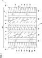
- Fig. 1 is a development view of a tread portion 2 of a tyre 1 according to an embodiment of the present invention.
- the tyre 1 in this embodiment can be used for various tyres such as a pneumatic tyre for a passenger car and for heavy load, and a non-pneumatic tyre not filled with pressurized air therein, for example.
- the tyre 1 in this embodiment is suitably used as a pneumatic tyre for a passenger car, for example.
- the tyre 1 in this embodiment has a tread portion 2 which is to be in contact with a road surface during running. It is preferred that the tread portion 2 has a land region 5 divided by a first edge 3 extending in the tyre circumferential direction and a second edge 4 extending in the tyre circumferential direction.
- the land region 5 in this embodiment will be described below with a crown land region 13 as a representative example of the land region 5.
- Fig. 2 is an enlarged view of the land region 5.
- the land region 5 is provided with a plurality of sipes 6 extending between the first edge 3 and the second edge 4.
- the land region 5 configured as such can ensure a large edge effect by the plurality of the sipes 6, therefore, it is possible that the on-ice/on-snow performance of the tyre 1 is improved.
- the plurality of the sipes 6 in this embodiment includes inclined sipes 7 and bent sipes 8.
- Each of the inclined sipes 7 is inclined in a first direction with respect to a tyre axial direction, for example.
- each of the bent sipes 8 includes first inclined elements 8A inclined in the first direction with respect to the tyre axial direction and a second inclined element 8B inclined in an opposite direction to the first direction.
- the plurality of the sipes 6 in this embodiment includes the inclined sipes 7 and the bent sipes 8, therefore, the land region 5 is less liable to be twisted, thereby, it is possible that damage of the land region 5 is suppressed even when an excessive load is applied thereto. Therefore, the durability performance of the tyre 1 in this embodiment is improved. Further, it is possible that the bent sipes 8 disperse a load applied to the land region 5 tyre axial direction by the first inclined elements 8A and the second inclined element 8B, therefore, the rigidity of the land region 5 is increased, thereby, it is possible that the steering stability performance on a dry road surface of the tyre 1 is improved.
- Fig. 3 is a cross-sectional view taken along A-A line of Fig. 2 .
- each of the inclined sipes 7 in this embodiment is configured to have a larger depth at a center portion (7b) thereof than at both end portions (7a) thereof.
- the depth of each of the inclined sipes 7 configured as such is not constant, therefore, decrease in the rigidity of the land region 5 is suppressed, thereby, it is possible that the steering stability performance on a dry road surface of the tyre 1 is improved.
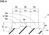
- Fig. 4 is a cross-sectional view taken along B-B line of Fig. 2 .
- each of the bent sipes 8 in this embodiment is configured to have a smaller depth at a center portion (8b) thereof than at both end portions (8a) thereof.
- the depth of each of the bent sipes 8 configured as such is not constant, therefore, decrease in the rigidity of the land region 5 is suppressed, thereby, it is possible that the steering stability performance on a dry road surface of the tyre 1 is improved.
- the inclined sipes 7 and the bent sipes 8 are arranged alternately in the tyre circumferential direction.
- the land region 5 provided with the inclined sipes 7 and the bent sipes 8 configured as such distribution of the rigidity thereof is made uniform, therefore, it is possible that the durability performance of the tyre 1 is further improved.
- each of the inclined sipes 7 extends linearly. It is preferred that each of the inclined sipes 7 is inclined at an angle ⁇ 1 in a range of from 25 to 30 degrees with respect to the tyre axial direction.
- the inclined sipes 7 configured as such exert larger edge effect in the tyre circumferential direction during running on an icy/snowy road surface, therefore, it is possible that the on-ice/on-snow performance of the tyre 1 is improved.
- tyre 1 dimensions and the like of various parts of the tyre 1 are those measured under a standard state unless noted otherwise. Further, lengths of various parts of the tyre 1 are those measured on an outer surface positioned outermost in a tyre radial direction of the tread portion 2.
- the "standard state” is a state in which the tyre 1 is mounted on a standard rim, inflated to a standard inner pressure, and loaded with no tyre load.
- the "standard rim” is a wheel rim specified for the concerned tyre by a standard included in a standardization system on which the tyre is based, for example, the "normal wheel rim” in JATMA, "Design Rim” in TRA, and “Measuring Rim” in ETRTO.
- the "standard inner pressure” is air pressure specified for the concerned tyre by a standard included in a standardization system on which the tyre is based, for example, the “maximum air pressure” in JATMA, maximum value listed in the "TIRE LOAD LIMITS AT VARIOUS COLD INFLATION PRESSURES" table in TRA, and "INFLATION PRESSURE” in ETRTO.
- each of the bent sipes 8 is composed of the first inclined elements 8A and the second inclined element 8B configured to be linear. It is preferred that each of the first inclined elements 8A is inclined at an angle ⁇ 2 in a range of from 25 to 30 degrees with respect to the tyre axial direction. Further, it is preferred that the second inclined element 8B is inclined at an angle ⁇ 3 in a range of from 30 to 35 degrees with respect to the tyre axial direction.
- bent sipes 8 configured as such exert the edge effects in the tyre circumferential direction and the tyre axial direction in a good balance during running on an icy/snowy road surface, therefore, it is possible that the on-ice/on-snow performance of the tyre 1 is improved.
- the inclined sipes 7 and the first inclined elements 8A extend in parallel to each other. It is possible that the inclined sipes 7 and the first inclined elements 8A configured as such exert larger edge effect in the tyre circumferential direction during running on an icy/snowy road surface.
- both end portions (7a) has an equal length L1 in the tyre axial direction. Further, it is preferred that a length L2 in the tyre axial direction of the center portion (7b) is equal to the length L1 in the tyre axial direction of each of the end portions (7a).
- the inclined sipes 7 configured as such have a uniform change in the depth, therefore, the rigidity of the land region 5 is distributed in a good balance, thereby, it is possible that the durability performance of the tyre 1 is improved.
- each of the bent sipes 8 in this embodiment are composed of the first inclined elements 8A and the center portion (8b) is composed of the second inclined element 8B. It is preferred that each of the first inclined elements 8A forming the end portions (8a) has an equal length L3 in the tyre axial direction. Further, it is preferred that a length L4 in the tyre axial direction of the second inclined element 8B is larger than the length L3 in the tyre axial direction of each of the first inclined elements 8A.
- the length L4 in the tyre axial direction having a different inclination direction is large, therefore, the rigidity of the land region 5 is distributed in a good balance as a whole, thereby, it is possible that the durability performance of the tyre 1 is improved.
- the length L4 in the tyre axial direction of the second inclined element 8B is in a range of from 110% to 135% of the length L2 in the tyre axial direction of the center portion (7b) of each of the inclined sipes 7. It is possible that the inclined sipes 7 and the bent sipes 8 configured as such make the rigidity of the land region 5 proper in a good balance as a whole, therefore, it is possible that the steering stability performance on a dry road surface of the tyre 1 is improved.
- the land region 5 in this embodiment is provided with first lateral grooves 9 each extending from the first edge 3 to terminate within the land region 5 and second lateral grooves 10 each extending from the second edge 4 to terminate within the land region 5. It is preferred that the first lateral grooves 9 and the second lateral grooves 10 are arranged alternately in the tyre circumferential direction.
- the land region 5 configured as such is not provided with a lateral groove crossing the land region 5, therefore, the rigidity thereof is maintained, thereby, it is possible that the steering stability performance on a dry road surface of the tyre 1 is improved.
- the first lateral grooves 9 and the second lateral grooves 10 form snow blocks therein and shear them, therefore, the on-ice/on-snow performance of the tyre 1 is improved.
- a length L6 in the tyre axial direction of each of the second lateral grooves 10 in this embodiment is equal to a length L5 in the tyre axial direction of each of the first lateral grooves 9. It is preferred that the length L5 in the tyre axial direction of each of the first lateral grooves 9 and the length L6 in the tyre axial direction of each of the second lateral grooves 10 are each smaller than the length L1 in the tyre axial direction of the end portions (7a) of each of the inclined sipes 7.
- the length L5 in the tyre axial direction of each of the first lateral grooves 9 and the length L6 in the tyre axial direction of each of the second lateral grooves 10 are each larger than the length L3 in the tyre axial direction of the end portions (8a) of each of the bent sipes 8.
- the first lateral grooves 9 and the second lateral grooves 10 extend in parallel to each other, for example. It is possible that the first lateral grooves 9 and the second lateral grooves 10 configured as such improve the on-ice/on-snow performance of the tyre 1 in a good balance with respect to the tyre axial direction.
- an angle ⁇ 4 of each of the first lateral grooves 9 with respect to the tyre axial direction is in a range of from 25 to 30 degrees.
- an angle ⁇ 5 of each of the second lateral grooves 10 with respect to the tyre axial direction is in a range of from 25 to 30 degrees.
- each of the first lateral grooves 9 and the second lateral grooves 10 extends in parallel with the inclined sipes 7. It is possible that the first lateral grooves 9 and the second lateral grooves 10 configured as such, together with the inclined sipes 7, improve the on-ice/on-snow performance of the tyre 1.
- each combination of one first lateral groove 9, one second lateral groove 10, and one bent sipe 8 adjacent to each other at least one of the first lateral groove 9 and the second lateral groove 10 is arranged on an extended line of a corresponding one of the first inclined elements 8A of the bent sipe 8.
- Each of the first lateral groove 9 and the second lateral groove 10 in this embodiment is arranged on the extended line of a respective one of the first inclined elements 8A. It is possible that the first lateral grooves 9 and the second lateral grooves 10 configured as such, together with the first inclined elements 8A, further improve the on-ice/on-snow performance of the tyre 1.
- the tread portion 2 in this embodiment has crown vertical grooves 11 extending in the tyre circumferential direction adjacently to a tyre equator (C) on both sides thereof and shoulder vertical grooves 12 each extending in the tyre circumferential direction between a respective one of the crown vertical grooves 11 and its adjacent one of tread edges (Te).
- C tyre equator
- shoulder vertical grooves 12 each extending in the tyre circumferential direction between a respective one of the crown vertical grooves 11 and its adjacent one of tread edges (Te).
- the tread edges (Te) are defined as outermost ground contacting positions in the tyre axial direction of the tyre 1 when the tyre 1 in the standard state is in contact with a flat surface with zero camber angle by being loaded with a standard tyre load.
- the center position in the tyre axial direction between the tread edges (Te) is the tyre equator (C).
- the "standard tyre load” is a tyre load specified for the concerned tyre by a standard included in a standardization system on which the tyre is based, for example, the "maximum load capacity" in JATMA, maximum value listed in “TIRE LOAD LIMITS AT VARIOUS COLD INFLATION PRESSURES" table in TRA, and "LOAD CAPACITY" in ETRTO.
- Each of the crown vertical grooves 11 and the shoulder vertical grooves 12 has a groove width of 2% or more of a tread width TW, for example.
- the tread width TW is a distance in the tyre axial direction between the tread edges (Te) in the standard state.
- the tread portion 2 in this embodiment has a plurality of land regions divided by the crown vertical grooves 11 and the shoulder vertical grooves 12. It is preferred that the plurality of the land region includes the crown land region 13 defined between the crown vertical grooves 11, middle land regions 14 each defined between a respective one of the crown vertical grooves 11 and its adjacent one of the shoulder vertical grooves 12, and shoulder land regions 15 each defined between a respective one of the shoulder vertical grooves 12 and its adjacent one of the tread edges (Te).
- the land region 5 defined between the first edge 3 and the second edge 4 in this embodiment is the crown land region 13 arranged on the tyre equator (C).
- the crown land region 13 in this embodiment is provided with the inclined sipes 7, the bent sipes 8, the first lateral grooves 9, and the second lateral grooves 10 described above.
- a depth (d1) of each of the end portions (7a) of the inclined sipes 7 is in a range of from 40% to 50% of a depth (D) of each of the crown vertical grooves 11. Further, it is preferred that a depth (d2) of the center portion (7b) of each of the inclined sipes 7 is in a range of from 65% to 70% of the depth (D) of each of the crown vertical grooves 11. It is preferred that depth (d2) of the center portion (7b) of each of the inclined sipes 7 is larger than the depth (d1) of each of the end portions (7a) by 1 mm or more.
- the inclined sipes 7 configured as such make the rigidity of the crown land region 13 proper, therefore, it is possible that the steering stability performance of the tyre 1 on a dry road surface is improved.
- a depth (d3) of each of the end portions (8a) of the bent sipes 8 is in a range of from 65% to 70% of the depth (D) of each of the crown vertical grooves 11. Further, it is preferred that a depth (d4) of the center portion (8b) of each of the bent sipes 8 is in a range of from 40% to 50% of the depth (D) of each of the crown vertical grooves 11. It is preferred that depth (d4) of the center portion (8b) of each of the bent sipes 8 is smaller than the depth (d3) of each of the end portions (8a) by 1 mm or more.
- the bent sipes 8 configured as such make the rigidity of the crown land region 13 proper, therefore, it is possible that the steering stability performance of the tyre 1 on a dry road surface is improved.
- Fig. 5 is a cross-sectional view taken along C-C line of Fig. 1 .
- a depth (d5) of each of the first lateral grooves 9 is in a range of from 70% to 75% of the depth (D) of each of the crown vertical grooves 11.
- a depth (d6) of each of the second lateral grooves 10 is in a range of from 70% to 75% of the depth (D) of each of the crown vertical grooves 11.
- the depth (d5) of each of the first lateral grooves 9 and the depth (d6) of each of the second lateral grooves 10 are equal to each other. It is possible that the first lateral grooves 9 and the second lateral grooves 10 configured as such improve the on-ice/on-snow performance of the tyre 1 in a good balance with respect to the tyre axial direction.
- Fig. 6 is an enlarged view of one of the middle land regions 14. As shown in Fig. 6 , each of the middle land regions 14 in this embodiment is provided with first middle lateral grooves 16 and second middle lateral grooves 17 extending from a respective one of the shoulder vertical grooves 12 and third middle lateral grooves 18 extending from a respective one of the crown vertical grooves 11.
- Each of the first middle lateral grooves 16 includes a first middle element 16A, a second middle element 16B, and a third middle element 16C, for example.
- the first middle element 16A extends in the tyre axial direction from a respective one of the shoulder vertical grooves 12, the second middle element 16B is connected with the first middle element 16A and extends therefrom, and the third middle element 16C extends in the tyre circumferential direction from the second middle element 16B, for example.
- the first middle lateral grooves 16 configured as such can exert snow shearing force in the tyre circumferential direction and the tyre axial direction, therefore, it is possible that the on-ice/on-snow performance of the tyre 1 is improved.
- first middle element 16A and the second middle element 16B extend continuously in the tyre axial direction.
- the third middle element 16C in this embodiment extends in a curved manner with respect to the tyre circumferential direction.
- the first middle lateral grooves 16 configured as such do not cross the middle land regions 14, therefore, the decrease in the rigidity of the middle land regions 14 is suppressed, thereby, it is possible that the high steering stability performance of the tyre 1 on a dry road surface is maintained.
- a depth (d7) of each of the first middle elements 16A is in a range of from 70% to 75% of the depth (D) of each of the crown vertical grooves 11.
- Each of the second middle elements 16B in this embodiment has a depth (d8) smaller than the depth (d7) of each of the first middle elements 16A.
- each of the third middle elements 16C has a depth (d9) smaller than the depth (d8) of each of the second middle elements 16B.
- the middle land regions 14 are less liable to be twisted, thereby, damage of the middle land regions 14 is suppressed even when an excessive load is applied thereto, therefore, it is possible that the durability performance of the tyre 1 is improved.
- each of the second middle lateral grooves 17 extends from the shoulder vertical grooves 12 to terminate within a respective one of the middle land regions 14. It is preferred that each of the third middle lateral grooves 18 extends from a respective one of the crown vertical grooves 11 to terminate within a respective one of the middle land regions.
- the second middle lateral grooves 17 and the third middle lateral grooves 18 configured as such form snow blocks therein and shear them, therefore, the on-ice/on-snow performance of the tyre 1 is improved.
- each of the second middle lateral grooves 17 has a chamfered portion (17a) at an opening portion (17b) thereof with a respective one of the shoulder vertical grooves 12, for example. It is possible that the second middle lateral grooves 17 configured as such, together with the shoulder vertical grooves 12, improve the on-ice/on-snow performance of the tyre 1.
- each of the third middle lateral grooves 18 has a chamfered portion (18a) at an opening portion (18b) thereof with a respective one of the crown vertical grooves 11, for example. It is preferred that the opening portion (18b) of each of the third middle lateral grooves 18 faces a respective one of the inclined sipes 7 of the crown land region 13 with a respective one of the crown vertical grooves 11 therebetween. It is possible that the third middle lateral grooves 18 configured as such, together with the crown vertical grooves 11 and the inclined sipes 7, improve the on-ice/on-snow performance tyre 1.
- Each of the second middle lateral grooves 17 is arranged on an extended line of the third middle element 16C of a respective one of the first middle lateral grooves 16, for example.
- Each of the third middle lateral grooves 18 in this embodiment is arranged on an extended line of a respective one of the second middle lateral grooves 17.
- each of the second middle lateral grooves 17 has a depth (d10) in a range of from 70% to 75% of the depth (D) of each of the crown vertical grooves 11.
- each of the third middle lateral grooves 18 has a depth (d11) in a range of from 70% to 75% of the depth (D) of each of the crown vertical grooves 11.
- the depth (d10) of each of the second middle lateral grooves 17 and the depth (d11) of each of the third middle lateral grooves 18 are equal to each other. It is possible that the second middle lateral grooves 17 and the third middle lateral grooves 18 configured as such improve the on-ice/on-snow performance of the tyre 1 in a good balance with respect to the tyre axial direction.
- each of the middle land regions 14 in this embodiment is provided with first middle sipes 19 and second middle sipes 20.
- Each of the first middle sipes 19 extends from a respective one of the shoulder vertical grooves 12 to terminate within a respective one of the middle land regions 14.
- Each of the second middle sipes 20 extends from a respective one of the crown vertical grooves 11 to terminate within a respective one of the middle land regions 14. It is preferred that each of the second middle sipes 20 is arranged on an extended line of a respective one of the first middle sipes 19.
- first middle sipes 19 and the second middle sipes 20 configured as such cooperate with each other to exert a large edge effect, therefore, both of the steering stability performance on a dry road surface and the on-ice/on-snow performance of the tyre 1 are exerted without decreasing the rigidity of the middle land regions 14.
- the third middle element 16C is arranged between the first middle sipe 19 and the second middle sipe 20 in this embodiment.
- the first middle lateral grooves 16, the first middle sipes 19, and the second middle sipes 20 configured as such cooperate with each other to improve the on-ice/on-snow performance of the tyre 1 while maintaining the rigidity of the middle land regions 14 high.
- each of the middle land regions 14 is provided with third middle sipes each connecting between a respective one of the first middle lateral grooves 16 and its adjacent one of the crown vertical grooves 11.
- Each of the third middle sipes connects between the second middle element 16B of a respective one of the first middle lateral grooves 16 and its adjacent one of the crown vertical grooves 11, for example. It is possible that the third middle sipes configured as such improve the on-ice/on-snow performance of the tyre 1 by the edge effect thereof, while maintaining the high rigidity of the middle land regions 14.
- the shoulder land regions 15 in this embodiment is provided with first shoulder lateral grooves 22, second shoulder lateral grooves 23, and shoulder sipes 24.
- Each of the first shoulder lateral grooves 22, the second shoulder lateral grooves 23, and the shoulder sipes 24 extends from a respective one of the tread edges (Te) in the tyre axial direction. It is preferred that each of the shoulder land regions 15 is provided with a narrow groove 25 extending continuously in the tyre circumferential direction.
- each of the first shoulder lateral grooves 22 in this embodiment extends from the tread edge (Te) and beyond the narrow groove 25 to the shoulder vertical groove 12. It is preferred that each of the first shoulder lateral grooves 22 has a chamfered portion (22a) at an opening portion (22b) thereof with its adjacent one of the shoulder vertical grooves 12.
- the first shoulder lateral grooves 22 configured as such form snow blocks therein and shear them, therefore, the on-ice/on-snow performance of the tyre 1 is improved. Further, it is possible that the first shoulder lateral grooves 22 cooperate with the shoulder vertical grooves 12 to improve the on-ice/on-snow performance of the tyre 1.
- Each of the second shoulder lateral grooves 23 in this embodiment extends from a respective one of the tread edges (Te) to a respective one of the narrow grooves 25.
- the second shoulder lateral grooves 23 configured as such form snow blocks therein and shear them, therefore, the on-ice/on-snow performance of the tyre 1 is improved.
- the second shoulder lateral grooves 23 do not cross the shoulder land regions 15, therefore, the rigidity of the shoulder land regions 15 is increased, thereby, it is possible that the steering stability performance of the tyre 1 on a dry road surface is improved.
- first shoulder lateral grooves 22 and the second shoulder lateral grooves 23 are arranged alternately in the tyre circumferential direction.
- the shoulder land regions 15 provided with the first shoulder lateral grooves 22 and the second shoulder lateral grooves 23 configured as such disperses the rigidity thereof in a good balance, therefore, It is possible that the durability performance of the tyre 1 is improved.
- Each of the shoulder sipes 24 in this embodiment extends from a respective one of the tread edges (Te) to its adjacent one of the narrow grooves 25. At least one shoulder sipe 24, two shoulder sipes 24 in this embodiment, is arranged between each pair of the first shoulder lateral groove 22 and the second shoulder lateral groove 23 adjacent to each other in the tyre circumferential direction. It is possible that the shoulder sipes 24 configured as such improve the on-ice/on-snow performance of the tyre 1 by the edge effect thereof while maintaining the rigidity of the shoulder land regions 15 high.
- a groove width of each of the narrow grooves 25 is smaller than 2% of the tread width TW, for example. It is possible that the narrow grooves 25 configured as such exert large edge effect in the tyre axial direction and improve the on-ice/on-snow performance of the tyre 1 while maintaining the rigidity of the shoulder land regions 15 high.
- Tyres having the basic pattern shown in Fig. 1 were made by way of test according to the specifications listed in Table 1. Each of the test tyres was tested for the steering stability performance, the on-ice/on-snow performance, and the durability performance. Common specifications of each of the test tyres and the test methods were as follows. Tyre size: 215/60R16 Tyre rim: 16 x 6.5J
- test tyres were mounted on all wheels of a test vehicle of front wheel drive mid-size passenger car and then inflated to a tyre inner pressure of 240 kPa. While a test driver drove the test vehicle on a dry road surface, the steering stability performance was evaluated by the driver's feeling. The test results are indicated by an index based on Reference 1 being 100, wherein the larger the numerical value, the better the steering stability performance is.
- test tyres were mounted on all wheels of the test vehicle of front wheel drive mid-size passenger car and then inflated to the tyre inner pressure of 240 kPa. While the test driver drove the test vehicle on an icy/snowy road surface, the steering stability performance was evaluated by the driver's feeling. The test results are indicated by an index based on the Reference 1 being 100, wherein the larger the numerical value, the better the on-ice/on-snow performance is.
- test tyres were inflated to a tyre inner pressure of 220 kPa and mounted on a bench durability testing machine. Each of the test tyres was run at a speed equivalent to 120 km/h, and the durability performance was evaluated while the tyre load applied to the test tyre was changed stepwise. The test results are indicated by an index based on the Reference 1 being 100, wherein the larger the numerical value, the better the durability performance is.
Abstract
Description
- The present invention relates to a tyre capable of improving durability performance while exerting both steering stability performance on a dry road surface and on-ice/on-snow performance.
- Conventionally, tyres having improved steering stability performance on an icy and snowy road surface (hereinafter referred to as "on-ice/on-snow performance") have been known. Japanese Unexamined Patent Application Publication No.
2016-203703 - However, the tyre disclosed in the Patent Literature 1 is provided with the sipes connecting between the lateral grooves and the sipes crossing the land region, therefore, it is possible that rigidity of the land region is decreased, thereby, there has been room for improvement for the steering stability performance on a dry road surface. Further, each of the sipes crossing the land region provided in the tyre disclosed in the Patent Literature 1 has a constant depth, therefore, the land region is likely to be damaged when excessive load is applied to the land region, thereby, there has been room for improvement.
- The present invention was made in view of the above, and a primary object thereof is to provide a tyre capable of improving the durability performance while exerting both of the steering stability performance on a dry road surface and the on-ice/on-snow performance.
- In one aspect of the present invention, a tyre comprises a tread portion comprising a land region divided by a first edge extending in a tyre circumferential direction and a second edge extending in the tyre circumferential direction, wherein the land region is provided with a plurality of sipes each extending between the first edge and the second edge, the plurality of the sipes includes inclined sipes and bent sipes, the inclined sipes are inclined in a first direction with respect to a tyre axial direction, each of the bent sipes includes first inclined elements inclined in the first direction with respect to the tyre axial direction and a second inclined element inclined in a direction opposite to the first inclined elements with respect to the tyre axial direction, each of the inclined sipes is configured to have a depth larger at a center portion thereof than at both end portions thereof, and each of the bent sipes is configured to have a depth smaller at a center portion thereof than at both end portions thereof.
- In another aspect of the invention, it is preferred that the inclined sipes and the bent sipes are arranged alternately in the tyre circumferential direction.
- In another aspect of the invention, it is preferred that each of the inclined sipes extends linearly.
- In another aspect of the invention, it is preferred that each of the bent sipes is composed of the first inclined elements and the second inclined element configured to be linear.
- In another aspect of the invention, it is preferred that in each of the bent sipes, the end portions are formed by the first inclined elements and the center portion is formed by the second inclined element.
- In another aspect of the invention, it is preferred that the first inclined elements forming the end portions have an equal length to each other in the tyre axial direction.
- In another aspect of the invention, it is preferred that a length in the tyre axial direction of the second inclined element is larger than a length in the tyre axial direction of each of the first inclined elements.
- In another aspect of the invention, it is preferred that a length in the tyre axial direction of the second inclined element is in a range of from 110% to 135% of a length in the tyre axial direction of the center portion of each of the inclined sipes.
- In another aspect of the invention, it is preferred that the inclined sipes and the first inclined elements extend in parallel to each other.
- In another aspect of the invention, it is preferred that the land region is provided with first lateral grooves and second lateral grooves, each of the first lateral grooves extends from the first edge to terminate within the land region, each of the second lateral grooves extends from the second edge to terminate within the land region, and the first lateral grooves and the second lateral grooves are arranged alternately in the tyre circumferential direction.
- In another aspect of the invention, it is preferred that in a combination of one first lateral groove, one second lateral groove, and one bent sipe adjacent to each other, at least one of the first lateral groove and the second lateral groove is arranged on an extended line of a corresponding one of the first inclined elements of the bent sipe.
- In another aspect of the invention, it is preferred that a length in the tyre axial direction of each of the second lateral grooves is equal to a length in the tyre axial direction of each of the first lateral grooves.
- In another aspect of the invention, it is preferred that the land region is arranged on a tyre equator.
-
-
Fig. 1 is a development view of a tread portion of a tyre as an embodiment of the present invention. -
Fig. 2 is an enlarged view of a land region (crown land region). -
Fig. 3 is a cross-sectional view taken along A-A line ofFig. 2 . -
Fig. 4 is a cross-sectional view taken along B-B line ofFig. 2 . -
Fig. 5 is a cross-sectional view taken along C-C line ofFig. 1 . -
Fig. 6 is an enlarged view of a middle land region. - An embodiment of the present invention will now be described in conjunction with accompanying drawings.
-
Fig. 1 is a development view of atread portion 2 of a tyre 1 according to an embodiment of the present invention. The tyre 1 in this embodiment can be used for various tyres such as a pneumatic tyre for a passenger car and for heavy load, and a non-pneumatic tyre not filled with pressurized air therein, for example. The tyre 1 in this embodiment is suitably used as a pneumatic tyre for a passenger car, for example. - As shown in
Fig. 1 , the tyre 1 in this embodiment has atread portion 2 which is to be in contact with a road surface during running. It is preferred that thetread portion 2 has aland region 5 divided by afirst edge 3 extending in the tyre circumferential direction and asecond edge 4 extending in the tyre circumferential direction. Although not particularly limited, theland region 5 in this embodiment will be described below with acrown land region 13 as a representative example of theland region 5. -
Fig. 2 is an enlarged view of theland region 5. As shown inFig. 2 , it is preferred that theland region 5 is provided with a plurality ofsipes 6 extending between thefirst edge 3 and thesecond edge 4. Theland region 5 configured as such can ensure a large edge effect by the plurality of thesipes 6, therefore, it is possible that the on-ice/on-snow performance of the tyre 1 is improved. - The plurality of the
sipes 6 in this embodiment includesinclined sipes 7 andbent sipes 8. Each of theinclined sipes 7 is inclined in a first direction with respect to a tyre axial direction, for example. It is preferred that each of thebent sipes 8 includes firstinclined elements 8A inclined in the first direction with respect to the tyre axial direction and a secondinclined element 8B inclined in an opposite direction to the first direction. - The plurality of the
sipes 6 in this embodiment includes theinclined sipes 7 and thebent sipes 8, therefore, theland region 5 is less liable to be twisted, thereby, it is possible that damage of theland region 5 is suppressed even when an excessive load is applied thereto. Therefore, the durability performance of the tyre 1 in this embodiment is improved. Further, it is possible that thebent sipes 8 disperse a load applied to theland region 5 tyre axial direction by the firstinclined elements 8A and the secondinclined element 8B, therefore, the rigidity of theland region 5 is increased, thereby, it is possible that the steering stability performance on a dry road surface of the tyre 1 is improved. -
Fig. 3 is a cross-sectional view taken along A-A line ofFig. 2 . As shown inFig. 3 , each of theinclined sipes 7 in this embodiment is configured to have a larger depth at a center portion (7b) thereof than at both end portions (7a) thereof. The depth of each of theinclined sipes 7 configured as such is not constant, therefore, decrease in the rigidity of theland region 5 is suppressed, thereby, it is possible that the steering stability performance on a dry road surface of the tyre 1 is improved. -
Fig. 4 is a cross-sectional view taken along B-B line ofFig. 2 . As shown inFig. 4 , each of thebent sipes 8 in this embodiment is configured to have a smaller depth at a center portion (8b) thereof than at both end portions (8a) thereof. The depth of each of thebent sipes 8 configured as such is not constant, therefore, decrease in the rigidity of theland region 5 is suppressed, thereby, it is possible that the steering stability performance on a dry road surface of the tyre 1 is improved. - As shown in
Figs. 2 to 4 , in theland region 5 provided with theinclined sipes 7 and thebent sipes 8 configured as such, a change in the depth of theinclined sipes 7 is different from a change in the depth of thebent sipes 8, therefore, theland region 5 is less liable to be twisted, thereby, it is possible that damage of theland region 5 is suppressed even when an excessive load is applied thereto. Therefore, in the tyre 1 in this embodiment, the durability performance is improved while both of the steering stability performance on a dry road surface and the on-ice/on-snow performance are exerted. - As shown in
Fig. 2 , it is preferred that theinclined sipes 7 and thebent sipes 8 are arranged alternately in the tyre circumferential direction. In theland region 5 provided with theinclined sipes 7 and thebent sipes 8 configured as such, distribution of the rigidity thereof is made uniform, therefore, it is possible that the durability performance of the tyre 1 is further improved. - It is preferred that each of the
inclined sipes 7 extends linearly. It is preferred that each of theinclined sipes 7 is inclined at an angle θ1 in a range of from 25 to 30 degrees with respect to the tyre axial direction. Theinclined sipes 7 configured as such exert larger edge effect in the tyre circumferential direction during running on an icy/snowy road surface, therefore, it is possible that the on-ice/on-snow performance of the tyre 1 is improved. - In this specification, dimensions and the like of various parts of the tyre 1 are those measured under a standard state unless noted otherwise. Further, lengths of various parts of the tyre 1 are those measured on an outer surface positioned outermost in a tyre radial direction of the
tread portion 2. Here, in a case of a pneumatic tyre, the "standard state" is a state in which the tyre 1 is mounted on a standard rim, inflated to a standard inner pressure, and loaded with no tyre load. - The "standard rim" is a wheel rim specified for the concerned tyre by a standard included in a standardization system on which the tyre is based, for example, the "normal wheel rim" in JATMA, "Design Rim" in TRA, and "Measuring Rim" in ETRTO.
- The "standard inner pressure" is air pressure specified for the concerned tyre by a standard included in a standardization system on which the tyre is based, for example, the "maximum air pressure" in JATMA, maximum value listed in the "TIRE LOAD LIMITS AT VARIOUS COLD INFLATION PRESSURES" table in TRA, and "INFLATION PRESSURE" in ETRTO.
- It is preferred that each of the
bent sipes 8 is composed of the firstinclined elements 8A and the secondinclined element 8B configured to be linear. It is preferred that each of the firstinclined elements 8A is inclined at an angle θ2 in a range of from 25 to 30 degrees with respect to the tyre axial direction. Further, it is preferred that the secondinclined element 8B is inclined at an angle θ3 in a range of from 30 to 35 degrees with respect to the tyre axial direction. It is possible that thebent sipes 8 configured as such exert the edge effects in the tyre circumferential direction and the tyre axial direction in a good balance during running on an icy/snowy road surface, therefore, it is possible that the on-ice/on-snow performance of the tyre 1 is improved. - It is preferred that the
inclined sipes 7 and the firstinclined elements 8A extend in parallel to each other. It is possible that theinclined sipes 7 and the firstinclined elements 8A configured as such exert larger edge effect in the tyre circumferential direction during running on an icy/snowy road surface. - As shown in
Fig. 2 andFig. 3 , it is preferred that both end portions (7a) has an equal length L1 in the tyre axial direction. Further, it is preferred that a length L2 in the tyre axial direction of the center portion (7b) is equal to the length L1 in the tyre axial direction of each of the end portions (7a). Theinclined sipes 7 configured as such have a uniform change in the depth, therefore, the rigidity of theland region 5 is distributed in a good balance, thereby, it is possible that the durability performance of the tyre 1 is improved. - As shown in
Fig. 2 andFig. 4 , in each of thebent sipes 8 in this embodiment, the end portions (8a) are composed of the firstinclined elements 8A and the center portion (8b) is composed of the secondinclined element 8B. It is preferred that each of the firstinclined elements 8A forming the end portions (8a) has an equal length L3 in the tyre axial direction. Further, it is preferred that a length L4 in the tyre axial direction of the secondinclined element 8B is larger than the length L3 in the tyre axial direction of each of the firstinclined elements 8A. In thebent sipes 8 configured as such, the length L4 in the tyre axial direction having a different inclination direction is large, therefore, the rigidity of theland region 5 is distributed in a good balance as a whole, thereby, it is possible that the durability performance of the tyre 1 is improved. - As shown in
Figs. 2 to 4 , it is preferred that the length L4 in the tyre axial direction of the secondinclined element 8B is in a range of from 110% to 135% of the length L2 in the tyre axial direction of the center portion (7b) of each of theinclined sipes 7. It is possible that theinclined sipes 7 and thebent sipes 8 configured as such make the rigidity of theland region 5 proper in a good balance as a whole, therefore, it is possible that the steering stability performance on a dry road surface of the tyre 1 is improved. - As shown in
Fig. 2 , theland region 5 in this embodiment is provided with firstlateral grooves 9 each extending from thefirst edge 3 to terminate within theland region 5 and secondlateral grooves 10 each extending from thesecond edge 4 to terminate within theland region 5. It is preferred that the firstlateral grooves 9 and the secondlateral grooves 10 are arranged alternately in the tyre circumferential direction. Theland region 5 configured as such is not provided with a lateral groove crossing theland region 5, therefore, the rigidity thereof is maintained, thereby, it is possible that the steering stability performance on a dry road surface of the tyre 1 is improved. Further, the firstlateral grooves 9 and the secondlateral grooves 10 form snow blocks therein and shear them, therefore, the on-ice/on-snow performance of the tyre 1 is improved. - A length L6 in the tyre axial direction of each of the second
lateral grooves 10 in this embodiment is equal to a length L5 in the tyre axial direction of each of the firstlateral grooves 9. It is preferred that the length L5 in the tyre axial direction of each of the firstlateral grooves 9 and the length L6 in the tyre axial direction of each of the secondlateral grooves 10 are each smaller than the length L1 in the tyre axial direction of the end portions (7a) of each of theinclined sipes 7. Further, it is preferred that the length L5 in the tyre axial direction of each of the firstlateral grooves 9 and the length L6 in the tyre axial direction of each of the secondlateral grooves 10 are each larger than the length L3 in the tyre axial direction of the end portions (8a) of each of thebent sipes 8. The firstlateral grooves 9 and the secondlateral grooves 10 extend in parallel to each other, for example. It is possible that the firstlateral grooves 9 and the secondlateral grooves 10 configured as such improve the on-ice/on-snow performance of the tyre 1 in a good balance with respect to the tyre axial direction. - It is preferred that an angle θ4 of each of the first
lateral grooves 9 with respect to the tyre axial direction is in a range of from 25 to 30 degrees. Further, it is preferred that an angle θ5 of each of the secondlateral grooves 10 with respect to the tyre axial direction is in a range of from 25 to 30 degrees. It is preferred that each of the firstlateral grooves 9 and the secondlateral grooves 10 extends in parallel with theinclined sipes 7. It is possible that the firstlateral grooves 9 and the secondlateral grooves 10 configured as such, together with theinclined sipes 7, improve the on-ice/on-snow performance of the tyre 1. - It is preferred that, in each combination of one first
lateral groove 9, one secondlateral groove 10, and onebent sipe 8 adjacent to each other, at least one of the firstlateral groove 9 and the secondlateral groove 10 is arranged on an extended line of a corresponding one of the firstinclined elements 8A of thebent sipe 8. Each of the firstlateral groove 9 and the secondlateral groove 10 in this embodiment is arranged on the extended line of a respective one of the firstinclined elements 8A. It is possible that the firstlateral grooves 9 and the secondlateral grooves 10 configured as such, together with the firstinclined elements 8A, further improve the on-ice/on-snow performance of the tyre 1. - As shown in
Fig. 1 , thetread portion 2 in this embodiment has crownvertical grooves 11 extending in the tyre circumferential direction adjacently to a tyre equator (C) on both sides thereof and shouldervertical grooves 12 each extending in the tyre circumferential direction between a respective one of the crownvertical grooves 11 and its adjacent one of tread edges (Te). - Here, in a case of a pneumatic tyre, the tread edges (Te) are defined as outermost ground contacting positions in the tyre axial direction of the tyre 1 when the tyre 1 in the standard state is in contact with a flat surface with zero camber angle by being loaded with a standard tyre load. The center position in the tyre axial direction between the tread edges (Te) is the tyre equator (C).
- The "standard tyre load" is a tyre load specified for the concerned tyre by a standard included in a standardization system on which the tyre is based, for example, the "maximum load capacity" in JATMA, maximum value listed in "TIRE LOAD LIMITS AT VARIOUS COLD INFLATION PRESSURES" table in TRA, and "LOAD CAPACITY" in ETRTO.
- Each of the crown
vertical grooves 11 and the shouldervertical grooves 12 has a groove width of 2% or more of a tread width TW, for example. Here, the tread width TW is a distance in the tyre axial direction between the tread edges (Te) in the standard state. - The
tread portion 2 in this embodiment has a plurality of land regions divided by the crownvertical grooves 11 and the shouldervertical grooves 12. It is preferred that the plurality of the land region includes thecrown land region 13 defined between the crownvertical grooves 11,middle land regions 14 each defined between a respective one of the crownvertical grooves 11 and its adjacent one of the shouldervertical grooves 12, andshoulder land regions 15 each defined between a respective one of the shouldervertical grooves 12 and its adjacent one of the tread edges (Te). - As shown in
Fig. 1 andFig. 2 , theland region 5 defined between thefirst edge 3 and thesecond edge 4 in this embodiment is thecrown land region 13 arranged on the tyre equator (C). Thereby, thecrown land region 13 in this embodiment is provided with theinclined sipes 7, thebent sipes 8, the firstlateral grooves 9, and the secondlateral grooves 10 described above. - As shown in
Fig. 3 , it is preferred that a depth (d1) of each of the end portions (7a) of theinclined sipes 7 is in a range of from 40% to 50% of a depth (D) of each of the crownvertical grooves 11. Further, it is preferred that a depth (d2) of the center portion (7b) of each of theinclined sipes 7 is in a range of from 65% to 70% of the depth (D) of each of the crownvertical grooves 11. It is preferred that depth (d2) of the center portion (7b) of each of theinclined sipes 7 is larger than the depth (d1) of each of the end portions (7a) by 1 mm or more. Theinclined sipes 7 configured as such make the rigidity of thecrown land region 13 proper, therefore, it is possible that the steering stability performance of the tyre 1 on a dry road surface is improved. - As shown in
Fig. 4 , it is preferred that a depth (d3) of each of the end portions (8a) of thebent sipes 8 is in a range of from 65% to 70% of the depth (D) of each of the crownvertical grooves 11. Further, it is preferred that a depth (d4) of the center portion (8b) of each of thebent sipes 8 is in a range of from 40% to 50% of the depth (D) of each of the crownvertical grooves 11. It is preferred that depth (d4) of the center portion (8b) of each of thebent sipes 8 is smaller than the depth (d3) of each of the end portions (8a) by 1 mm or more. Thebent sipes 8 configured as such make the rigidity of thecrown land region 13 proper, therefore, it is possible that the steering stability performance of the tyre 1 on a dry road surface is improved. -
Fig. 5 is a cross-sectional view taken along C-C line ofFig. 1 . As shown inFig. 5 , it is preferred that a depth (d5) of each of the firstlateral grooves 9 is in a range of from 70% to 75% of the depth (D) of each of the crownvertical grooves 11. It is preferred that a depth (d6) of each of the secondlateral grooves 10 is in a range of from 70% to 75% of the depth (D) of each of the crownvertical grooves 11. It is preferred that the depth (d5) of each of the firstlateral grooves 9 and the depth (d6) of each of the secondlateral grooves 10 are equal to each other. It is possible that the firstlateral grooves 9 and the secondlateral grooves 10 configured as such improve the on-ice/on-snow performance of the tyre 1 in a good balance with respect to the tyre axial direction. -
Fig. 6 is an enlarged view of one of themiddle land regions 14. As shown inFig. 6 , each of themiddle land regions 14 in this embodiment is provided with first middlelateral grooves 16 and second middlelateral grooves 17 extending from a respective one of the shouldervertical grooves 12 and third middlelateral grooves 18 extending from a respective one of the crownvertical grooves 11. - Each of the first middle
lateral grooves 16 includes a firstmiddle element 16A, a secondmiddle element 16B, and a thirdmiddle element 16C, for example. The firstmiddle element 16A extends in the tyre axial direction from a respective one of the shouldervertical grooves 12, the secondmiddle element 16B is connected with the firstmiddle element 16A and extends therefrom, and the thirdmiddle element 16C extends in the tyre circumferential direction from the secondmiddle element 16B, for example. The first middlelateral grooves 16 configured as such can exert snow shearing force in the tyre circumferential direction and the tyre axial direction, therefore, it is possible that the on-ice/on-snow performance of the tyre 1 is improved. - It is preferred that the first
middle element 16A and the secondmiddle element 16B extend continuously in the tyre axial direction. The thirdmiddle element 16C in this embodiment extends in a curved manner with respect to the tyre circumferential direction. The first middlelateral grooves 16 configured as such do not cross themiddle land regions 14, therefore, the decrease in the rigidity of themiddle land regions 14 is suppressed, thereby, it is possible that the high steering stability performance of the tyre 1 on a dry road surface is maintained. - As shown in
Fig. 5 , it is preferred that a depth (d7) of each of the firstmiddle elements 16A is in a range of from 70% to 75% of the depth (D) of each of the crownvertical grooves 11. Each of the secondmiddle elements 16B in this embodiment has a depth (d8) smaller than the depth (d7) of each of the firstmiddle elements 16A. It is preferred that each of the thirdmiddle elements 16C has a depth (d9) smaller than the depth (d8) of each of the secondmiddle elements 16B. By the first middlelateral grooves 16 configured as such, themiddle land regions 14 are less liable to be twisted, thereby, damage of themiddle land regions 14 is suppressed even when an excessive load is applied thereto, therefore, it is possible that the durability performance of the tyre 1 is improved. - As shown in
Fig. 6 , it is preferred that each of the second middlelateral grooves 17 extends from the shouldervertical grooves 12 to terminate within a respective one of themiddle land regions 14. It is preferred that each of the third middlelateral grooves 18 extends from a respective one of the crownvertical grooves 11 to terminate within a respective one of the middle land regions. The second middlelateral grooves 17 and the third middlelateral grooves 18 configured as such form snow blocks therein and shear them, therefore, the on-ice/on-snow performance of the tyre 1 is improved. - It is preferred that each of the second middle
lateral grooves 17 has a chamfered portion (17a) at an opening portion (17b) thereof with a respective one of the shouldervertical grooves 12, for example. It is possible that the second middlelateral grooves 17 configured as such, together with the shouldervertical grooves 12, improve the on-ice/on-snow performance of the tyre 1. - It is preferred that each of the third middle
lateral grooves 18 has a chamfered portion (18a) at an opening portion (18b) thereof with a respective one of the crownvertical grooves 11, for example. It is preferred that the opening portion (18b) of each of the third middlelateral grooves 18 faces a respective one of theinclined sipes 7 of thecrown land region 13 with a respective one of the crownvertical grooves 11 therebetween. It is possible that the third middlelateral grooves 18 configured as such, together with the crownvertical grooves 11 and theinclined sipes 7, improve the on-ice/on-snow performance tyre 1. - Each of the second middle
lateral grooves 17 is arranged on an extended line of the thirdmiddle element 16C of a respective one of the first middlelateral grooves 16, for example. Each of the third middlelateral grooves 18 in this embodiment is arranged on an extended line of a respective one of the second middlelateral grooves 17. Thereby, the first middlelateral grooves 16, the second middlelateral grooves 17, and the third middlelateral grooves 18 cooperate with each other to improve the on-ice/on-snow performance of the tyre 1. - As shown in
Fig. 5 , it is preferred that each of the second middlelateral grooves 17 has a depth (d10) in a range of from 70% to 75% of the depth (D) of each of the crownvertical grooves 11. It is preferred that each of the third middlelateral grooves 18 has a depth (d11) in a range of from 70% to 75% of the depth (D) of each of the crownvertical grooves 11. It is preferred that the depth (d10) of each of the second middlelateral grooves 17 and the depth (d11) of each of the third middlelateral grooves 18 are equal to each other. It is possible that the second middlelateral grooves 17 and the third middlelateral grooves 18 configured as such improve the on-ice/on-snow performance of the tyre 1 in a good balance with respect to the tyre axial direction. - As shown in
Fig. 6 , each of themiddle land regions 14 in this embodiment is provided with firstmiddle sipes 19 and secondmiddle sipes 20. Each of the firstmiddle sipes 19 extends from a respective one of the shouldervertical grooves 12 to terminate within a respective one of themiddle land regions 14. Each of the secondmiddle sipes 20 extends from a respective one of the crownvertical grooves 11 to terminate within a respective one of themiddle land regions 14. It is preferred that each of the secondmiddle sipes 20 is arranged on an extended line of a respective one of the firstmiddle sipes 19. It is possible that the firstmiddle sipes 19 and the secondmiddle sipes 20 configured as such cooperate with each other to exert a large edge effect, therefore, both of the steering stability performance on a dry road surface and the on-ice/on-snow performance of the tyre 1 are exerted without decreasing the rigidity of themiddle land regions 14. - In each combination of one third
middle element 16C, onefirst middle sipe 19 and onesecond middle sipe 20 adjacent to each other, the thirdmiddle element 16C is arranged between the firstmiddle sipe 19 and the secondmiddle sipe 20 in this embodiment. The first middlelateral grooves 16, the firstmiddle sipes 19, and the secondmiddle sipes 20 configured as such cooperate with each other to improve the on-ice/on-snow performance of the tyre 1 while maintaining the rigidity of themiddle land regions 14 high. - It is preferred that each of the
middle land regions 14 is provided with third middle sipes each connecting between a respective one of the first middlelateral grooves 16 and its adjacent one of the crownvertical grooves 11. Each of the third middle sipes connects between the secondmiddle element 16B of a respective one of the first middlelateral grooves 16 and its adjacent one of the crownvertical grooves 11, for example. It is possible that the third middle sipes configured as such improve the on-ice/on-snow performance of the tyre 1 by the edge effect thereof, while maintaining the high rigidity of themiddle land regions 14. - As shown in
Fig. 1 , theshoulder land regions 15 in this embodiment is provided with firstshoulder lateral grooves 22, secondshoulder lateral grooves 23, andshoulder sipes 24. Each of the firstshoulder lateral grooves 22, the secondshoulder lateral grooves 23, and theshoulder sipes 24 extends from a respective one of the tread edges (Te) in the tyre axial direction. It is preferred that each of theshoulder land regions 15 is provided with anarrow groove 25 extending continuously in the tyre circumferential direction. - In each of the
shoulder land regions 15, each of the firstshoulder lateral grooves 22 in this embodiment extends from the tread edge (Te) and beyond thenarrow groove 25 to the shouldervertical groove 12. It is preferred that each of the firstshoulder lateral grooves 22 has a chamfered portion (22a) at an opening portion (22b) thereof with its adjacent one of the shouldervertical grooves 12. The firstshoulder lateral grooves 22 configured as such form snow blocks therein and shear them, therefore, the on-ice/on-snow performance of the tyre 1 is improved. Further, it is possible that the firstshoulder lateral grooves 22 cooperate with the shouldervertical grooves 12 to improve the on-ice/on-snow performance of the tyre 1. - Each of the second
shoulder lateral grooves 23 in this embodiment extends from a respective one of the tread edges (Te) to a respective one of thenarrow grooves 25. The secondshoulder lateral grooves 23 configured as such form snow blocks therein and shear them, therefore, the on-ice/on-snow performance of the tyre 1 is improved. Further, the secondshoulder lateral grooves 23 do not cross theshoulder land regions 15, therefore, the rigidity of theshoulder land regions 15 is increased, thereby, it is possible that the steering stability performance of the tyre 1 on a dry road surface is improved. - It is preferred that the first
shoulder lateral grooves 22 and the secondshoulder lateral grooves 23 are arranged alternately in the tyre circumferential direction. Theshoulder land regions 15 provided with the firstshoulder lateral grooves 22 and the secondshoulder lateral grooves 23 configured as such disperses the rigidity thereof in a good balance, therefore, It is possible that the durability performance of the tyre 1 is improved. - Each of the
shoulder sipes 24 in this embodiment extends from a respective one of the tread edges (Te) to its adjacent one of thenarrow grooves 25. At least oneshoulder sipe 24, twoshoulder sipes 24 in this embodiment, is arranged between each pair of the firstshoulder lateral groove 22 and the secondshoulder lateral groove 23 adjacent to each other in the tyre circumferential direction. It is possible that theshoulder sipes 24 configured as such improve the on-ice/on-snow performance of the tyre 1 by the edge effect thereof while maintaining the rigidity of theshoulder land regions 15 high. - A groove width of each of the
narrow grooves 25 is smaller than 2% of the tread width TW, for example. It is possible that thenarrow grooves 25 configured as such exert large edge effect in the tyre axial direction and improve the on-ice/on-snow performance of the tyre 1 while maintaining the rigidity of theshoulder land regions 15 high. - While detailed description has been made of the tyres as especially preferred embodiments of the present invention, the present invention can be embodied in various forms without being limited to the illustrated embodiments.
- Tyres having the basic pattern shown in
Fig. 1 were made by way of test according to the specifications listed in Table 1. Each of the test tyres was tested for the steering stability performance, the on-ice/on-snow performance, and the durability performance.
Common specifications of each of the test tyres and the test methods were as follows.
Tyre size: 215/60R16
Tyre rim: 16 x 6.5J - Each of the test tyres was mounted on all wheels of a test vehicle of front wheel drive mid-size passenger car and then inflated to a tyre inner pressure of 240 kPa. While a test driver drove the test vehicle on a dry road surface, the steering stability performance was evaluated by the driver's feeling. The test results are indicated by an index based on Reference 1 being 100, wherein the larger the numerical value, the better the steering stability performance is.
- Each of the test tyres was mounted on all wheels of the test vehicle of front wheel drive mid-size passenger car and then inflated to the tyre inner pressure of 240 kPa. While the test driver drove the test vehicle on an icy/snowy road surface, the steering stability performance was evaluated by the driver's feeling. The test results are indicated by an index based on the Reference 1 being 100, wherein the larger the numerical value, the better the on-ice/on-snow performance is.
- Each of the test tyres was inflated to a tyre inner pressure of 220 kPa and mounted on a bench durability testing machine. Each of the test tyres was run at a speed equivalent to 120 km/h, and the durability performance was evaluated while the tyre load applied to the test tyre was changed stepwise. The test results are indicated by an index based on the Reference 1 being 100, wherein the larger the numerical value, the better the durability performance is.
- The test results are shown in Table 1.
Table 1 Ref.1 Ref.2 Ref.3 Ref.4 Ex.1 Ex.2 Ex.3 Magnitude relation between Depth (d1) at both End portions and Depth (d2) at Center portion of Inclined sipe d1=d2 d1<d2 d1<d2 d1<d2 d1<d2 d1<d2 d1<d2 Magnitude relation between Depth (d3) at both End portions and Depth (d4) at Center portion of Bent sipe d3>d4 d3=d4 d3<d4 d3>d4 d3>d4 d3>d4 d3>d4 Inclination direction of First inclined element and Second inclined element opposite opposite opposite same opposite opposite opposite Magnitude relation between Length L1 at both End portions and Length L2 at Center portion of Inclined sipe L1=L2 L1=L2 L1=L2 L1=L2 L1=L2 L1<L2 L1=L2 Magnitude relation between Length L3 at both End portions and Length L4 at Center portion of Bent sipe L3<L4 L3<L4 L3<L4 L3<L4 L3<L4 L3<L4 L3=L4 Steering stability performance [index] 100 100 85 100 105 100 100 On-ice/on-snow performance [index] 100 95 95 75 110 100 105 Durability performance [index] 100 95 105 100 120 110 105 - From the test results, it was confirmed that the durability performance is improved while both the steering stability performance on a dry road surface and the on-ice/on-snow performance are exerted in a good balance for the tyres as the Examples as compared with the tyres as the References.
Claims (13)
- A tyre comprising a tread portion comprising a land region divided by a first edge extending in a tyre circumferential direction and a second edge extending in the tyre circumferential direction, wherein
the land region is provided with a plurality of sipes each extending between the first edge and the second edge,
the plurality of the sipes includes inclined sipes and bent sipes,
the inclined sipes are inclined in a first direction with respect to a tyre axial direction,
each of the bent sipes includes first inclined elements inclined in the first direction with respect to the tyre axial direction and a second inclined element inclined in a direction opposite to the first inclined elements with respect to the tyre axial direction,
each of the inclined sipes is configured to have a depth larger at a center portion thereof than at both end portions thereof, and
each of the bent sipes is configured to have a depth smaller at a center portion thereof than at both end portions thereof. - The tyre according to claim 1, wherein
the inclined sipes and the bent sipes are arranged alternately in the tyre circumferential direction. - The tyre according to claim 1 or 2, wherein
each of the inclined sipes extends linearly. - The tyre according to any one of claims 1 to 3, wherein
each of the bent sipes is composed of the first inclined elements and the second inclined element configured to be linear. - The tyre according to any one of claims 1 to 4, wherein
in each of the bent sipes, the end portions are formed by the first inclined elements and the center portion is formed by the second inclined element. - The tyre according to claim 5, wherein
the first inclined elements forming the end portions have an equal length to each other in the tyre axial direction. - The tyre according to claim 5 or 6, wherein
a length in the tyre axial direction of the second inclined element is larger than a length in the tyre axial direction of each of the first inclined elements. - The tyre according to any one of claims 5 to 7, wherein
a length in the tyre axial direction of the second inclined element is in a range of from 110% to 135% of a length in the tyre axial direction of the center portion of each of the inclined sipes. - The tyre according to any one of claims 1 to 8, wherein
the inclined sipes and the first inclined elements extend in parallel to each other. - The tyre according to any one of claims 1 to 9, wherein
the land region is provided with first lateral grooves and second lateral grooves,
each of the first lateral grooves extends from the first edge to terminate within the land region,
each of the second lateral grooves extends from the second edge to terminate within the land region, and
the first lateral grooves and the second lateral grooves are arranged alternately in the tyre circumferential direction. - The tyre according to claim 10, wherein
in a combination of one first lateral groove, one second lateral groove, and one bent sipe adjacent to each other, at least one of the first lateral groove and the second lateral groove is arranged on an extended line of a corresponding one of the first inclined elements of the bent sipe. - The tyre according to claim 10 or 11, wherein
a length in the tyre axial direction of each of the second lateral grooves is equal to a length in the tyre axial direction of each of the first lateral grooves. - The tyre according to any one of claims 1 to 12, wherein
the land region is arranged on a tyre equator.
Applications Claiming Priority (1)
| Application Number | Priority Date | Filing Date | Title |
|---|---|---|---|
| JP2018074060A JP7056333B2 (en) | 2018-04-06 | 2018-04-06 | tire |
Publications (2)
| Publication Number | Publication Date |
|---|---|
| EP3549790A1 true EP3549790A1 (en) | 2019-10-09 |
| EP3549790B1 EP3549790B1 (en) | 2020-09-16 |
Family
ID=65717886
Family Applications (1)
| Application Number | Title | Priority Date | Filing Date |
|---|---|---|---|
| EP19161015.3A Active EP3549790B1 (en) | 2018-04-06 | 2019-03-06 | Tyre |
Country Status (5)
| Country | Link |
|---|---|
| US (1) | US11142026B2 (en) |
| EP (1) | EP3549790B1 (en) |
| JP (1) | JP7056333B2 (en) |
| KR (1) | KR102545452B1 (en) |
| CN (1) | CN110341391B (en) |
Families Citing this family (2)
| Publication number | Priority date | Publication date | Assignee | Title |
|---|---|---|---|---|
| US20230062051A1 (en) * | 2019-12-31 | 2023-03-02 | Sadi Kose | Tire having corkscrew sculpture with inverted central rib features |
| USD945355S1 (en) * | 2020-11-06 | 2022-03-08 | Sumitomo Rubber Industries, Ltd. | Tire for automobile |
Citations (9)
| Publication number | Priority date | Publication date | Assignee | Title |
|---|---|---|---|---|
| JPS61159203U (en) * | 1985-03-27 | 1986-10-02 | ||
| US5109904A (en) * | 1989-02-17 | 1992-05-05 | Sumitomo Rubber Industries, Ltd. | Snow tire |
| JP2010126076A (en) * | 2008-11-28 | 2010-06-10 | Bridgestone Corp | Tire |
| JP2010274846A (en) * | 2009-05-29 | 2010-12-09 | Bridgestone Corp | Tire |
| EP2639084A1 (en) * | 2012-03-15 | 2013-09-18 | Sumitomo Rubber Industries, Ltd. | Pneumatic tire |
| JP2015009789A (en) * | 2013-07-02 | 2015-01-19 | 住友ゴム工業株式会社 | Pneumatic tire |
| JP2016168991A (en) * | 2015-03-16 | 2016-09-23 | 住友ゴム工業株式会社 | Pneumatic tire |
| JP2016203703A (en) | 2015-04-17 | 2016-12-08 | 住友ゴム工業株式会社 | Pneumatic tire |
| EP3269565A1 (en) * | 2016-07-12 | 2018-01-17 | Sumitomo Rubber Industries, Ltd. | Tire |
Family Cites Families (15)
| Publication number | Priority date | Publication date | Assignee | Title |
|---|---|---|---|---|
| USD360859S (en) * | 1994-01-28 | 1995-08-01 | The Goodyear Tire & Rubber Company | Tire tread |
| JP4165728B2 (en) * | 2000-08-02 | 2008-10-15 | 東洋ゴム工業株式会社 | Pneumatic tire |
| JP4793129B2 (en) * | 2006-06-23 | 2011-10-12 | 横浜ゴム株式会社 | Pneumatic tire |
| JP5393404B2 (en) | 2009-11-05 | 2014-01-22 | 株式会社ブリヂストン | tire |
| JP5771398B2 (en) * | 2011-01-11 | 2015-08-26 | 株式会社ブリヂストン | Pneumatic tire |
| JP5291739B2 (en) * | 2011-03-02 | 2013-09-18 | 住友ゴム工業株式会社 | Pneumatic tire |
| JP5342622B2 (en) * | 2011-09-13 | 2013-11-13 | 住友ゴム工業株式会社 | Pneumatic tire |
| WO2013051053A1 (en) * | 2011-10-03 | 2013-04-11 | 株式会社ブリヂストン | Heavy duty pneumatic tire |
| JP5498466B2 (en) * | 2011-10-20 | 2014-05-21 | 住友ゴム工業株式会社 | Heavy duty tire |
| CN104349915B (en) * | 2013-01-23 | 2016-01-20 | 横滨橡胶株式会社 | Air-inflation tyre |
| EP2905150B1 (en) * | 2013-05-27 | 2016-01-06 | Sumitomo Rubber Industries Limited | Pneumatic tire |
| JP5997729B2 (en) * | 2014-07-17 | 2016-09-28 | 住友ゴム工業株式会社 | Pneumatic tire |
| EP3017963B1 (en) * | 2014-11-06 | 2019-05-29 | Sumitomo Rubber Industries Limited | Pneumatic tire |
| JP6473393B2 (en) * | 2015-07-13 | 2019-02-20 | 住友ゴム工業株式会社 | Pneumatic tire |
| JP6891572B2 (en) * | 2016-04-12 | 2021-06-18 | 住友ゴム工業株式会社 | Pneumatic tires |
-
2018
- 2018-04-06 JP JP2018074060A patent/JP7056333B2/en active Active
-
2019
- 2019-03-06 KR KR1020190025707A patent/KR102545452B1/en active IP Right Grant
- 2019-03-06 EP EP19161015.3A patent/EP3549790B1/en active Active
- 2019-03-11 US US16/297,761 patent/US11142026B2/en active Active
- 2019-03-15 CN CN201910197144.3A patent/CN110341391B/en active Active
Patent Citations (9)
| Publication number | Priority date | Publication date | Assignee | Title |
|---|---|---|---|---|
| JPS61159203U (en) * | 1985-03-27 | 1986-10-02 | ||
| US5109904A (en) * | 1989-02-17 | 1992-05-05 | Sumitomo Rubber Industries, Ltd. | Snow tire |
| JP2010126076A (en) * | 2008-11-28 | 2010-06-10 | Bridgestone Corp | Tire |
| JP2010274846A (en) * | 2009-05-29 | 2010-12-09 | Bridgestone Corp | Tire |
| EP2639084A1 (en) * | 2012-03-15 | 2013-09-18 | Sumitomo Rubber Industries, Ltd. | Pneumatic tire |
| JP2015009789A (en) * | 2013-07-02 | 2015-01-19 | 住友ゴム工業株式会社 | Pneumatic tire |
| JP2016168991A (en) * | 2015-03-16 | 2016-09-23 | 住友ゴム工業株式会社 | Pneumatic tire |
| JP2016203703A (en) | 2015-04-17 | 2016-12-08 | 住友ゴム工業株式会社 | Pneumatic tire |
| EP3269565A1 (en) * | 2016-07-12 | 2018-01-17 | Sumitomo Rubber Industries, Ltd. | Tire |
Also Published As
| Publication number | Publication date |
|---|---|
| US20190308465A1 (en) | 2019-10-10 |
| KR20190117369A (en) | 2019-10-16 |
| CN110341391B (en) | 2022-06-14 |
| JP2019182147A (en) | 2019-10-24 |
| KR102545452B1 (en) | 2023-06-19 |
| CN110341391A (en) | 2019-10-18 |
| JP7056333B2 (en) | 2022-04-19 |
| US11142026B2 (en) | 2021-10-12 |
| EP3549790B1 (en) | 2020-09-16 |
Similar Documents
| Publication | Publication Date | Title |
|---|---|---|
| EP3260308B1 (en) | Tire | |
| EP3178668B1 (en) | Pneumatic tire | |
| EP2578418B1 (en) | Pneumatic tire | |
| EP3042792B1 (en) | Pneumatic tire | |
| EP3260307B1 (en) | Tire | |
| EP3539798B1 (en) | Tyre | |
| EP3098089A1 (en) | Winter tire | |
| US11511567B2 (en) | Tyre | |
| EP3342605B1 (en) | Tire | |
| EP3549791B1 (en) | Tyre | |
| EP3552844B1 (en) | Tyre | |
| EP3098090A1 (en) | Winter tire | |
| EP3564047B1 (en) | Tyre | |
| US10981418B2 (en) | Tire | |
| EP3456552A1 (en) | Tire | |
| EP3403852A1 (en) | Tire | |
| EP3575110B1 (en) | Tyre | |
| EP3530488A1 (en) | Tyre for winter | |
| EP3546249B1 (en) | Tyre | |
| EP3549790B1 (en) | Tyre | |
| EP3988336B1 (en) | Tire | |
| EP4000961A1 (en) | Tyre | |
| EP4039506A1 (en) | Tire | |
| EP4201709A1 (en) | Tire |
Legal Events
| Date | Code | Title | Description |
|---|---|---|---|
| PUAI | Public reference made under article 153(3) epc to a published international application that has entered the european phase |
Free format text: ORIGINAL CODE: 0009012 |
|
| STAA | Information on the status of an ep patent application or granted ep patent |
Free format text: STATUS: THE APPLICATION HAS BEEN PUBLISHED |
|
| AK | Designated contracting states |
Kind code of ref document: A1 Designated state(s): AL AT BE BG CH CY CZ DE DK EE ES FI FR GB GR HR HU IE IS IT LI LT LU LV MC MK MT NL NO PL PT RO RS SE SI SK SM TR |
|
| AX | Request for extension of the european patent |
Extension state: BA ME |
|
| STAA | Information on the status of an ep patent application or granted ep patent |
Free format text: STATUS: REQUEST FOR EXAMINATION WAS MADE |
|
| 17P | Request for examination filed |
Effective date: 20191206 |
|
| RBV | Designated contracting states (corrected) |
Designated state(s): AL AT BE BG CH CY CZ DE DK EE ES FI FR GB GR HR HU IE IS IT LI LT LU LV MC MK MT NL NO PL PT RO RS SE SI SK SM TR |
|
| GRAP | Despatch of communication of intention to grant a patent |
Free format text: ORIGINAL CODE: EPIDOSNIGR1 |
|
| STAA | Information on the status of an ep patent application or granted ep patent |
Free format text: STATUS: GRANT OF PATENT IS INTENDED |
|
| RIC1 | Information provided on ipc code assigned before grant |
Ipc: B60C 11/12 20060101ALN20200325BHEP Ipc: B60C 11/03 20060101AFI20200325BHEP |
|
| RIC1 | Information provided on ipc code assigned before grant |
Ipc: B60C 11/12 20060101ALN20200401BHEP Ipc: B60C 11/03 20060101AFI20200401BHEP |
|
| INTG | Intention to grant announced |
Effective date: 20200417 |
|
| GRAS | Grant fee paid |
Free format text: ORIGINAL CODE: EPIDOSNIGR3 |
|
| GRAA | (expected) grant |
Free format text: ORIGINAL CODE: 0009210 |
|
| STAA | Information on the status of an ep patent application or granted ep patent |
Free format text: STATUS: THE PATENT HAS BEEN GRANTED |
|
| AK | Designated contracting states |
Kind code of ref document: B1 Designated state(s): AL AT BE BG CH CY CZ DE DK EE ES FI FR GB GR HR HU IE IS IT LI LT LU LV MC MK MT NL NO PL PT RO RS SE SI SK SM TR |
|
| REG | Reference to a national code |
Ref country code: GB Ref legal event code: FG4D |
|
| REG | Reference to a national code |
Ref country code: CH Ref legal event code: EP |
|
| REG | Reference to a national code |
Ref country code: DE Ref legal event code: R096 Ref document number: 602019000670 Country of ref document: DE |
|
| REG | Reference to a national code |
Ref country code: IE Ref legal event code: FG4D |
|
| REG | Reference to a national code |
Ref country code: AT Ref legal event code: REF Ref document number: 1313825 Country of ref document: AT Kind code of ref document: T Effective date: 20201015 |
|
| PG25 | Lapsed in a contracting state [announced via postgrant information from national office to epo] |
Ref country code: BG Free format text: LAPSE BECAUSE OF FAILURE TO SUBMIT A TRANSLATION OF THE DESCRIPTION OR TO PAY THE FEE WITHIN THE PRESCRIBED TIME-LIMIT Effective date: 20201216 Ref country code: HR Free format text: LAPSE BECAUSE OF FAILURE TO SUBMIT A TRANSLATION OF THE DESCRIPTION OR TO PAY THE FEE WITHIN THE PRESCRIBED TIME-LIMIT Effective date: 20200916 Ref country code: GR Free format text: LAPSE BECAUSE OF FAILURE TO SUBMIT A TRANSLATION OF THE DESCRIPTION OR TO PAY THE FEE WITHIN THE PRESCRIBED TIME-LIMIT Effective date: 20201217 Ref country code: NO Free format text: LAPSE BECAUSE OF FAILURE TO SUBMIT A TRANSLATION OF THE DESCRIPTION OR TO PAY THE FEE WITHIN THE PRESCRIBED TIME-LIMIT Effective date: 20201216 Ref country code: SE Free format text: LAPSE BECAUSE OF FAILURE TO SUBMIT A TRANSLATION OF THE DESCRIPTION OR TO PAY THE FEE WITHIN THE PRESCRIBED TIME-LIMIT Effective date: 20200916 Ref country code: FI Free format text: LAPSE BECAUSE OF FAILURE TO SUBMIT A TRANSLATION OF THE DESCRIPTION OR TO PAY THE FEE WITHIN THE PRESCRIBED TIME-LIMIT Effective date: 20200916 |
|
| REG | Reference to a national code |
Ref country code: AT Ref legal event code: MK05 Ref document number: 1313825 Country of ref document: AT Kind code of ref document: T Effective date: 20200916 |
|
| REG | Reference to a national code |
Ref country code: NL Ref legal event code: MP Effective date: 20200916 |
|
| PG25 | Lapsed in a contracting state [announced via postgrant information from national office to epo] |
Ref country code: RS Free format text: LAPSE BECAUSE OF FAILURE TO SUBMIT A TRANSLATION OF THE DESCRIPTION OR TO PAY THE FEE WITHIN THE PRESCRIBED TIME-LIMIT Effective date: 20200916 Ref country code: LV Free format text: LAPSE BECAUSE OF FAILURE TO SUBMIT A TRANSLATION OF THE DESCRIPTION OR TO PAY THE FEE WITHIN THE PRESCRIBED TIME-LIMIT Effective date: 20200916 |
|
| REG | Reference to a national code |
Ref country code: LT Ref legal event code: MG4D |
|
| PG25 | Lapsed in a contracting state [announced via postgrant information from national office to epo] |
Ref country code: PT Free format text: LAPSE BECAUSE OF FAILURE TO SUBMIT A TRANSLATION OF THE DESCRIPTION OR TO PAY THE FEE WITHIN THE PRESCRIBED TIME-LIMIT Effective date: 20210118 Ref country code: RO Free format text: LAPSE BECAUSE OF FAILURE TO SUBMIT A TRANSLATION OF THE DESCRIPTION OR TO PAY THE FEE WITHIN THE PRESCRIBED TIME-LIMIT Effective date: 20200916 Ref country code: CZ Free format text: LAPSE BECAUSE OF FAILURE TO SUBMIT A TRANSLATION OF THE DESCRIPTION OR TO PAY THE FEE WITHIN THE PRESCRIBED TIME-LIMIT Effective date: 20200916 Ref country code: EE Free format text: LAPSE BECAUSE OF FAILURE TO SUBMIT A TRANSLATION OF THE DESCRIPTION OR TO PAY THE FEE WITHIN THE PRESCRIBED TIME-LIMIT Effective date: 20200916 Ref country code: LT Free format text: LAPSE BECAUSE OF FAILURE TO SUBMIT A TRANSLATION OF THE DESCRIPTION OR TO PAY THE FEE WITHIN THE PRESCRIBED TIME-LIMIT Effective date: 20200916 Ref country code: SM Free format text: LAPSE BECAUSE OF FAILURE TO SUBMIT A TRANSLATION OF THE DESCRIPTION OR TO PAY THE FEE WITHIN THE PRESCRIBED TIME-LIMIT Effective date: 20200916 |
|
| PG25 | Lapsed in a contracting state [announced via postgrant information from national office to epo] |
Ref country code: IS Free format text: LAPSE BECAUSE OF FAILURE TO SUBMIT A TRANSLATION OF THE DESCRIPTION OR TO PAY THE FEE WITHIN THE PRESCRIBED TIME-LIMIT Effective date: 20210116 Ref country code: PL Free format text: LAPSE BECAUSE OF FAILURE TO SUBMIT A TRANSLATION OF THE DESCRIPTION OR TO PAY THE FEE WITHIN THE PRESCRIBED TIME-LIMIT Effective date: 20200916 Ref country code: AT Free format text: LAPSE BECAUSE OF FAILURE TO SUBMIT A TRANSLATION OF THE DESCRIPTION OR TO PAY THE FEE WITHIN THE PRESCRIBED TIME-LIMIT Effective date: 20200916 Ref country code: AL Free format text: LAPSE BECAUSE OF FAILURE TO SUBMIT A TRANSLATION OF THE DESCRIPTION OR TO PAY THE FEE WITHIN THE PRESCRIBED TIME-LIMIT Effective date: 20200916 Ref country code: ES Free format text: LAPSE BECAUSE OF FAILURE TO SUBMIT A TRANSLATION OF THE DESCRIPTION OR TO PAY THE FEE WITHIN THE PRESCRIBED TIME-LIMIT Effective date: 20200916 |
|
| REG | Reference to a national code |
Ref country code: DE Ref legal event code: R097 Ref document number: 602019000670 Country of ref document: DE |
|
| PG25 | Lapsed in a contracting state [announced via postgrant information from national office to epo] |
Ref country code: SK Free format text: LAPSE BECAUSE OF FAILURE TO SUBMIT A TRANSLATION OF THE DESCRIPTION OR TO PAY THE FEE WITHIN THE PRESCRIBED TIME-LIMIT Effective date: 20200916 |
|
| PLBE | No opposition filed within time limit |
Free format text: ORIGINAL CODE: 0009261 |
|
| STAA | Information on the status of an ep patent application or granted ep patent |
Free format text: STATUS: NO OPPOSITION FILED WITHIN TIME LIMIT |
|
| 26N | No opposition filed |
Effective date: 20210617 |
|
| PG25 | Lapsed in a contracting state [announced via postgrant information from national office to epo] |
Ref country code: DK Free format text: LAPSE BECAUSE OF FAILURE TO SUBMIT A TRANSLATION OF THE DESCRIPTION OR TO PAY THE FEE WITHIN THE PRESCRIBED TIME-LIMIT Effective date: 20200916 Ref country code: SI Free format text: LAPSE BECAUSE OF FAILURE TO SUBMIT A TRANSLATION OF THE DESCRIPTION OR TO PAY THE FEE WITHIN THE PRESCRIBED TIME-LIMIT Effective date: 20200916 |
|
| PG25 | Lapsed in a contracting state [announced via postgrant information from national office to epo] |
Ref country code: MC Free format text: LAPSE BECAUSE OF FAILURE TO SUBMIT A TRANSLATION OF THE DESCRIPTION OR TO PAY THE FEE WITHIN THE PRESCRIBED TIME-LIMIT Effective date: 20200916 Ref country code: IT Free format text: LAPSE BECAUSE OF FAILURE TO SUBMIT A TRANSLATION OF THE DESCRIPTION OR TO PAY THE FEE WITHIN THE PRESCRIBED TIME-LIMIT Effective date: 20200916 |
|
| REG | Reference to a national code |
Ref country code: BE Ref legal event code: MM Effective date: 20210331 |
|
| PG25 | Lapsed in a contracting state [announced via postgrant information from national office to epo] |
Ref country code: LU Free format text: LAPSE BECAUSE OF NON-PAYMENT OF DUE FEES Effective date: 20210306 Ref country code: IE Free format text: LAPSE BECAUSE OF NON-PAYMENT OF DUE FEES Effective date: 20210306 |
|
| PG25 | Lapsed in a contracting state [announced via postgrant information from national office to epo] |
Ref country code: BE Free format text: LAPSE BECAUSE OF NON-PAYMENT OF DUE FEES Effective date: 20210331 |
|
| REG | Reference to a national code |
Ref country code: CH Ref legal event code: PL |
|
| PG25 | Lapsed in a contracting state [announced via postgrant information from national office to epo] |
Ref country code: LI Free format text: LAPSE BECAUSE OF NON-PAYMENT OF DUE FEES Effective date: 20220331 Ref country code: CH Free format text: LAPSE BECAUSE OF NON-PAYMENT OF DUE FEES Effective date: 20220331 |
|
| PGFP | Annual fee paid to national office [announced via postgrant information from national office to epo] |
Ref country code: FR Payment date: 20230208 Year of fee payment: 5 |
|
| PGFP | Annual fee paid to national office [announced via postgrant information from national office to epo] |
Ref country code: DE Payment date: 20230131 Year of fee payment: 5 |
|
| P01 | Opt-out of the competence of the unified patent court (upc) registered |
Effective date: 20230510 |
|
| PG25 | Lapsed in a contracting state [announced via postgrant information from national office to epo] |
Ref country code: NL Free format text: LAPSE BECAUSE OF NON-PAYMENT OF DUE FEES Effective date: 20200923 Ref country code: CY Free format text: LAPSE BECAUSE OF FAILURE TO SUBMIT A TRANSLATION OF THE DESCRIPTION OR TO PAY THE FEE WITHIN THE PRESCRIBED TIME-LIMIT Effective date: 20200916 |
|
| PG25 | Lapsed in a contracting state [announced via postgrant information from national office to epo] |
Ref country code: HU Free format text: LAPSE BECAUSE OF FAILURE TO SUBMIT A TRANSLATION OF THE DESCRIPTION OR TO PAY THE FEE WITHIN THE PRESCRIBED TIME-LIMIT; INVALID AB INITIO Effective date: 20190306 |
|
| GBPC | Gb: european patent ceased through non-payment of renewal fee |
Effective date: 20230306 |
|
| PG25 | Lapsed in a contracting state [announced via postgrant information from national office to epo] |
Ref country code: GB Free format text: LAPSE BECAUSE OF NON-PAYMENT OF DUE FEES Effective date: 20230306 |
|
| PG25 | Lapsed in a contracting state [announced via postgrant information from national office to epo] |
Ref country code: GB Free format text: LAPSE BECAUSE OF NON-PAYMENT OF DUE FEES Effective date: 20230306 |