EP3549485A1 - Stand-alone neck support - Google Patents
Stand-alone neck support Download PDFInfo
- Publication number
- EP3549485A1 EP3549485A1 EP18275184.2A EP18275184A EP3549485A1 EP 3549485 A1 EP3549485 A1 EP 3549485A1 EP 18275184 A EP18275184 A EP 18275184A EP 3549485 A1 EP3549485 A1 EP 3549485A1
- Authority
- EP
- European Patent Office
- Prior art keywords
- head support
- support member
- post
- base
- trunk
- Prior art date
- Legal status (The legal status is an assumption and is not a legal conclusion. Google has not performed a legal analysis and makes no representation as to the accuracy of the status listed.)
- Withdrawn
Links
- 230000014759 maintenance of location Effects 0.000 claims description 11
- 210000003128 head Anatomy 0.000 description 53
- 210000001061 forehead Anatomy 0.000 description 2
- 230000002093 peripheral effect Effects 0.000 description 2
- 230000000717 retained effect Effects 0.000 description 2
- 238000011161 development Methods 0.000 description 1
- 230000018109 developmental process Effects 0.000 description 1
- 230000000694 effects Effects 0.000 description 1
- 238000000034 method Methods 0.000 description 1
- 238000012986 modification Methods 0.000 description 1
- 230000004048 modification Effects 0.000 description 1
- 238000002560 therapeutic procedure Methods 0.000 description 1
Images
Classifications
-
- A—HUMAN NECESSITIES
- A47—FURNITURE; DOMESTIC ARTICLES OR APPLIANCES; COFFEE MILLS; SPICE MILLS; SUCTION CLEANERS IN GENERAL
- A47C—CHAIRS; SOFAS; BEDS
- A47C7/00—Parts, details, or accessories of chairs or stools
- A47C7/36—Supports for the head or the back
- A47C7/38—Supports for the head or the back for the head, e.g. detachable
- A47C7/383—Detachable or loose head- or neck-supports, e.g. horse-shoe shaped
-
- A—HUMAN NECESSITIES
- A47—FURNITURE; DOMESTIC ARTICLES OR APPLIANCES; COFFEE MILLS; SPICE MILLS; SUCTION CLEANERS IN GENERAL
- A47B—TABLES; DESKS; OFFICE FURNITURE; CABINETS; DRAWERS; GENERAL DETAILS OF FURNITURE
- A47B11/00—Tables with tops revolvable on vertical spindles
-
- A—HUMAN NECESSITIES
- A47—FURNITURE; DOMESTIC ARTICLES OR APPLIANCES; COFFEE MILLS; SPICE MILLS; SUCTION CLEANERS IN GENERAL
- A47B—TABLES; DESKS; OFFICE FURNITURE; CABINETS; DRAWERS; GENERAL DETAILS OF FURNITURE
- A47B23/00—Bed-tables; Trays; Reading-racks; Book-rests, i.e. items used in combination with something else
-
- A—HUMAN NECESSITIES
- A47—FURNITURE; DOMESTIC ARTICLES OR APPLIANCES; COFFEE MILLS; SPICE MILLS; SUCTION CLEANERS IN GENERAL
- A47C—CHAIRS; SOFAS; BEDS
- A47C16/00—Stand-alone rests or supports for feet, legs, arms, back or head
-
- A—HUMAN NECESSITIES
- A47—FURNITURE; DOMESTIC ARTICLES OR APPLIANCES; COFFEE MILLS; SPICE MILLS; SUCTION CLEANERS IN GENERAL
- A47C—CHAIRS; SOFAS; BEDS
- A47C20/00—Head-, foot- or like rests for beds, sofas or the like
- A47C20/02—Head-, foot- or like rests for beds, sofas or the like of detachable type
- A47C20/026—Supports for lying in a prone position
-
- A—HUMAN NECESSITIES
- A47—FURNITURE; DOMESTIC ARTICLES OR APPLIANCES; COFFEE MILLS; SPICE MILLS; SUCTION CLEANERS IN GENERAL
- A47C—CHAIRS; SOFAS; BEDS
- A47C20/00—Head-, foot- or like rests for beds, sofas or the like
- A47C20/04—Head-, foot- or like rests for beds, sofas or the like with adjustable inclination
-
- A—HUMAN NECESSITIES
- A61—MEDICAL OR VETERINARY SCIENCE; HYGIENE
- A61H—PHYSICAL THERAPY APPARATUS, e.g. DEVICES FOR LOCATING OR STIMULATING REFLEX POINTS IN THE BODY; ARTIFICIAL RESPIRATION; MASSAGE; BATHING DEVICES FOR SPECIAL THERAPEUTIC OR HYGIENIC PURPOSES OR SPECIFIC PARTS OF THE BODY
- A61H37/00—Accessories for massage
-
- A—HUMAN NECESSITIES
- A61—MEDICAL OR VETERINARY SCIENCE; HYGIENE
- A61H—PHYSICAL THERAPY APPARATUS, e.g. DEVICES FOR LOCATING OR STIMULATING REFLEX POINTS IN THE BODY; ARTIFICIAL RESPIRATION; MASSAGE; BATHING DEVICES FOR SPECIAL THERAPEUTIC OR HYGIENIC PURPOSES OR SPECIFIC PARTS OF THE BODY
- A61H2201/00—Characteristics of apparatus not provided for in the preceding codes
- A61H2201/01—Constructive details
- A61H2201/0157—Constructive details portable
-
- A—HUMAN NECESSITIES
- A61—MEDICAL OR VETERINARY SCIENCE; HYGIENE
- A61H—PHYSICAL THERAPY APPARATUS, e.g. DEVICES FOR LOCATING OR STIMULATING REFLEX POINTS IN THE BODY; ARTIFICIAL RESPIRATION; MASSAGE; BATHING DEVICES FOR SPECIAL THERAPEUTIC OR HYGIENIC PURPOSES OR SPECIFIC PARTS OF THE BODY
- A61H2201/00—Characteristics of apparatus not provided for in the preceding codes
- A61H2201/01—Constructive details
- A61H2201/0161—Size reducing arrangements when not in use, for stowing or transport
-
- A—HUMAN NECESSITIES
- A61—MEDICAL OR VETERINARY SCIENCE; HYGIENE
- A61H—PHYSICAL THERAPY APPARATUS, e.g. DEVICES FOR LOCATING OR STIMULATING REFLEX POINTS IN THE BODY; ARTIFICIAL RESPIRATION; MASSAGE; BATHING DEVICES FOR SPECIAL THERAPEUTIC OR HYGIENIC PURPOSES OR SPECIFIC PARTS OF THE BODY
- A61H2201/00—Characteristics of apparatus not provided for in the preceding codes
- A61H2201/16—Physical interface with patient
- A61H2201/1602—Physical interface with patient kind of interface, e.g. head rest, knee support or lumbar support
- A61H2201/1604—Head
-
- A—HUMAN NECESSITIES
- A61—MEDICAL OR VETERINARY SCIENCE; HYGIENE
- A61H—PHYSICAL THERAPY APPARATUS, e.g. DEVICES FOR LOCATING OR STIMULATING REFLEX POINTS IN THE BODY; ARTIFICIAL RESPIRATION; MASSAGE; BATHING DEVICES FOR SPECIAL THERAPEUTIC OR HYGIENIC PURPOSES OR SPECIFIC PARTS OF THE BODY
- A61H2203/00—Additional characteristics concerning the patient
- A61H2203/04—Position of the patient
- A61H2203/0443—Position of the patient substantially horizontal
- A61H2203/0468—Prone
Definitions
- the present invention relates generally to the field of stand-alone neck supports. More particularly, but not exclusively, the present invention concerns a stand-alone head support for prone positioning of a user's head at an elevated location from a ground surface.
- Head rests that provide comfort for a user in the prone position are known. Both medical and masseur professionals use such head rests to support a patient's head and neck in the face-down prone position whilst working on said patient.
- US 6694551 B in which a tubular frame supports a webbing stretched thereacross.
- the frame is inclined and the webbing provides an aperture to receive a face.
- the device is made for engagement with the same surface as a user, e.g. lying on the floor.
- use adjacent an elevated surface, such as a sunbed would be awkward and would render the user's head in an inadequately supported position.
- US 5970546 is a portable headrest for sunbathing.
- a head support member and a base support member provide a slightly elevated position of a face above a ground-surface.
- the device is made for engagement with the same surface as a user, e.g. lying on the floor and use adjacent a sunbed would exhibit the same problems.
- a portable prone head support device comprising a head support member and a frame, the head support member providing a face aperture adapted to receive a user's face in prone position, the frame having a trunk and a base, the trunk being adapted to locate the head support member at a distance from said base, characterised in that the base of the frame is adapted to provide a stable engagement with a ground surface, and the trunk is adjustable in at least one plane to allow positioning of the head support member relative to a second surface elevated from said ground surface.
- head support can be provided at a required position relative to a sunbed, lounger, or other such elevated surface from which a user's head may extend in a prone position.
- the ground-engaging base makes the device stand-alone for use with a range of beds/ chairs, etc.
- the stable engagement with a ground surface minimises the possibility of the device toppling in use, whilst the adjustable trunk provides optimal comfort positioning for the neck in particular to minimise strain.
- the trunk is adjustable to increase or decrease the distance between the base and the head support member.
- the trunk comprises a post for attachment to the head support member and the base.
- the post that can be raised and lowered relative to the base.
- the base comprises a retention arrangement for the post.
- the retention arrangement comprises a bore through which the post passes.
- the bore is open ended and comprises a loosening and tightening means, which may be in the form of a set screw with a user handle.
- the retention arrangement may comprise an aperture sheath to receive said post with corresponding apertures thereon and a location means to pass through aligned apertures in said post and sheath.
- the post may be telescopically altered in length.
- the post comprises a fixing plate at an upper end thereof for attachment to an underside of the head support member.
- the fixing plate is offset on the head support member one side biased towards a forehead-engaging portion of the support member.
- the trunk is adjustable to incline the head support member relative to the trunk.
- the trunk comprises a hinge proximal to the upper end of the post.
- the post comprises a short upper section for attachment to said head support member and a longer lower section for engagement with the base.
- the hinge comprises at least 90° rotation about a vertical plane, most preferably, up to 180° rotation.
- the hinge comprises a user-adjustable retention lever to hold the rotation angle selected.
- the base comprises at least three legs.
- the legs are adapted to rotate between a splayed position, providing a wide base perimeter and a contracted position providing a condensed substantially linear arrangement approximately in line with the post.
- the base comprises a hinge body to which each leg is rotatably attached.
- the hinge body may comprise the bore of the retention arrangement described above.
- the head support member is substantially C-shaped.
- the head support member is padded.
- the face aperture is substantially keyhole-shaped.
- the face aperture comprises further cut-out sections to accommodate spectacle frames being worn.
- the head support is adapted to receive a removable towel component.
- the head support member may comprise fixings for a removable towel component.
- the fixings comprise a hook/ loop fastening system installed on the underside of the head support component and at suitably cooperative locations on a shaped towel component.
- the portable head support device comprises a platform located between the base and the head support member.
- the platform is attached to the lower section of the post.
- the platform comprises a sheath for slidable engagement with the post.
- the sheath extends from an underside of the platform.
- the sheath is located on a central axis of the platform towards a top end of the platform, more preferably in a top half of the platform along the central axis.
- the sheath is located at approximately a third of the distance of the length of the central axis from the top end.
- the sheath comprises a tight slidable fit with the post to allow for positioning of the platform along the length of the post.
- the sheath may comprise a retaining means, which may be a headed set screw or other suitable mechanimsm.
- the platform comprises a prop between the sheath and the underside of the platform, which may be in the form of a diagonally arranged strut/ brace or a substantially triangular bracket.
- the platform comprises at least one cup holder in the form of a shallow cylindrical bore (open-ended), or well.
- cup holders are arranged on opposing sides of the central axis.
- the cup holder(s) is(are) located within a top third of the platform.
- the platform comprises a peripheral upstanding rim.
- the device is at least partially collapsible for portability.
- the head support member is rotatably via the hinge to tuck against the lower section of the post.
- the legs are rotatable contractable into a linear arrangement with the post, either upwardly against the post, or downwardly in line with the post.
- the platform may comprise hinged sections either side of the sheath for foldability in linear arrangement with the post.
- the device is at least partially disassembled for portability.
- the post is detachable from the legs, most preferably from the hinge body.
- the platform is slidably removable from the post.
- the head support member may also be detachable from the post.
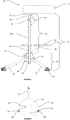
- Figures 1 to 5 show a portable prone head support device according to an exemplary embodiment.
- a portable prone head support device 10 comprises a head support member 12 and a frame 14, the head support member 12 providing a face aperture 16 adapted to receive a user's face in prone position, the frame 14 having a trunk 18 and a base 20, the trunk 18 being adapted to locate the head support member 12 at a distance from said base 20, characterised in that the base 20 of the frame 14 is adapted to provide a stable engagement with a ground surface, and the trunk 18 is adjustable in at least one plane to allow positioning of the head support member 12 relative to a second surface elevated from said ground surface.
- the head support member 12 is a substantially c-shaped component, surrounding the face aperture 16.
- the face aperture 16 is a keyhole shape, with a circular part 16a connected to an opening 16b within the head support member 12.
- the forehead and the cheeks of a face of a user is supported by a top side 12a of head support member 12 in a prone position, whilst providing adequate space for the chin to protrude through the opening 16b and for the eyes and the nose to be observable through the circular part 16a.
- a fixing plate 22 is mounted on an underside 12b of the head support member 12.
- the fixing plate is located approximately opposite the opening 16b opposite the portion of the top side 12a that would support the forehead of a user.
- the fixing plate 22 is attached to a short upper section of post 24a.
- a hinge 26 is attached to the short upper section of post 24a and the hinge 26 is attached to a long lower section of post 24b.
- a user-adjustable lever 26a is provided on the hinge 26 to allow for an angle A of the hinge to be adjusted and then retained in place.
- the angle A provides approximately up to 180° rotation to allow for the head support member 12 to be tilted backwards up to 90° (putting it in an upright position - although this is not likely to be required) and forwards up to 90° (putting it in a downward position - only likely to be required for storage and portability).
- a mid-range of movement across the 180° rotation allows for the head support member 12 to be tilted and fine-tuned according to a user's preference.
- the lower section of post 24b is slidably engaged with an open-ended bore 28 provided within a body 30.
- a handled set screw 34 is provided on the body 30 such that the screw extends through the body 30 into the bore 28 and is adjustable to loosen or tighten against the post 24b therein. This allows the position of the lower section of post 24b to be adjusted within the bore 28 in order to increase a length of the lower section of post 24b that is present above the body 30. Accordingly, this mechanism provides height adjustment for the head support member 12.
- the body 30 forms part of the base 20 and three equally-spaced legs 32 are rotatably mounted thereon.
- Each leg 32 comprises a fulcrum 32a at one end and a friction stopper 32b at an opposite free end.
- the legs 32 are able to rotate out to a splayed position in which the stoppers 32b establish a wide circular base perimeter upon contact with a ground surface.
- the legs 32 are able to rotate inwardly to a contracted position in which the legs 32 substantially meet.
- a table 40 is provided on the device 10.
- the table 40 comprises a platform 42 and a downwardly projecting sheath 44 that is located on a central axis B-B', towards a top end 42a of the platform 42.
- a triangular bracket 46 extends along the central axis from the sheath 44 to an underside 42d of the platform 42 in the direction of a bottom end 42b. The bracket provides support to the larger part of the platform 42a.
- Two cup holders 48 are provided in an upper face 42c of the platform 42 towards the top end 42a and either side of the central axis B-B'.
- the cup holders 48 are provided as substantially circular apertures through the platform 42 although it may be appreciated that these may be provided as a shallow well with a base instead.
- a substantially planar section 50 is provided as the majority of the upper face 42c of the platform 42.
- This planar section 50 comprises an upwardly protruding peripheral rim 52 therearound to retain items left on the table 40.
- the sheath 44 of the table 40 is slidably engaged around the lower section of post 24b.
- the platform 42 is ideally oriented with the planar section 50 located directly below the face aperture 16a, 16b of the head support member, which enables a user to view the items on the table 40, to, for example, read a book.
- the device 10 is made to be portable and for this reason, it is partially collapsible and disassembled. Therefore, in use, the device 10, is first assembled. This is achieved by extending the legs 32 from a contracted position to a splayed position and placing them on a ground surface.
- the table 40 is slidably engaged with the lower section of post 24b, but passing the post through the sheath 44 of the table 40 from the upper face 42c to the underside 42d.
- the set screw 34 in the body 30 is loosened to allow for the lower section of post 24b (with the hinge 26, upper section of post 24a and head support member 12 attached) to be slid into the bore 32a and retained by tightening the set screw 34 against the post 24b.
- the device 10 is then manoeuvred into position adjacent the top end of a sunbed/ bed or lounger onto which a user intends to adopt a prone position.
- the height of the device 10 relative to the bed is adjustable by raising or lowering the post 24b within the bore 32a and although personal preference dictates, it is generally intended that the top side 12a of the head support member 12 be approximately flush with the top end of the bed.
- the user can adjust the distance of the head support member 12 from the end of the bed for comfort, although it is generally appreciated that the head support member 12 would be very close to the top end of such bed.
- the user can now use the user-adjustable retention lever 26a to loosen the hinge 26 and adjust the angle A of the short section of post 24a (and therefore, the head support member attached thereto) relative to the long section of post 24b and the ground surface. Once the required angle A is achieved, the user-adjustable retention lever 26a is used to tighten the hinge and prevent further movement.
- the device 10 described herein provides a portable head support that can be used on a variety of sunbeds to achieve a comfortable prone lying position.
- the adjustability makes it suitable to fit the comfort requirements of each user.
- the ability to collapse and disassemble the device 10 makes it easy to transport. It also tackles the issue of wet and dirty poolside floors which may damage books and electrical equipment being used, whilst making it comfortable to view such items whilst using the device 10.
Landscapes
- Health & Medical Sciences (AREA)
- General Health & Medical Sciences (AREA)
- Nursing (AREA)
- Epidemiology (AREA)
- Pain & Pain Management (AREA)
- Physical Education & Sports Medicine (AREA)
- Rehabilitation Therapy (AREA)
- Life Sciences & Earth Sciences (AREA)
- Animal Behavior & Ethology (AREA)
- Public Health (AREA)
- Veterinary Medicine (AREA)
- Orthopedics, Nursing, And Contraception (AREA)
- Special Chairs (AREA)
Abstract
The invention relates to a portable prone head support device (10) comprising a head support member (12) and a frame (14), the head support member (12) providing a face aperture (16) adapted to receive a user's face in prone position, the frame (14) having a trunk (18) and a base (20), the trunk (18) being adapted to locate the head support member (12) at a distance from said base (20), characterised in that the base (20) of the frame (14) being adapted to provide a stable engagement with a ground surface, and the trunk (18) is adjustable in at least one plane to allow positioning of the head support member (12) relative to a second surface elevated from said ground surface, characterised in that the base (20) comprises at least three legs (32) and the legs (32) are adapted to rotate between a splayed position, providing a wide base perimeter, and a contracted position providing a condensed substantially linear arrangement approximately in line with the post.
Description
- The present invention relates generally to the field of stand-alone neck supports. More particularly, but not exclusively, the present invention concerns a stand-alone head support for prone positioning of a user's head at an elevated location from a ground surface.
- Head rests that provide comfort for a user in the prone position are known. Both medical and masseur professionals use such head rests to support a patient's head and neck in the face-down prone position whilst working on said patient.
- In the medical field, these are often in the form of a specifically apertured cushion that sits on the end of a bed through which a patient can breathe and see during a procedure. Massage therapists can acquire specially adapted beds with a face aperture through which a patient can breathe and see during a therapy session.
- Developments in the field have produced a number of prone head rests for personal use that provide support to the neck and head whilst lying face down, for example, during sunbathing.
- One such example is provided in
US 6694551 B , in which a tubular frame supports a webbing stretched thereacross. The frame is inclined and the webbing provides an aperture to receive a face. The device is made for engagement with the same surface as a user, e.g. lying on the floor. However, use adjacent an elevated surface, such as a sunbed would be awkward and would render the user's head in an inadequately supported position. - Another example is provided by
US 5970546 which is a portable headrest for sunbathing. A head support member and a base support member provide a slightly elevated position of a face above a ground-surface. Again, the device is made for engagement with the same surface as a user, e.g. lying on the floor and use adjacent a sunbed would exhibit the same problems. - It is an object of the present invention to address one or more of the problems of the prior art as discussed herein or otherwise.
- Therefore, it is now desired to provide an improved arrangement for a portable prone head support.
- According to the invention there is provided a portable prone head support device comprising a head support member and a frame, the head support member providing a face aperture adapted to receive a user's face in prone position, the frame having a trunk and a base, the trunk being adapted to locate the head support member at a distance from said base, characterised in that the base of the frame is adapted to provide a stable engagement with a ground surface, and the trunk is adjustable in at least one plane to allow positioning of the head support member relative to a second surface elevated from said ground surface.
- With this arrangement, head support can be provided at a required position relative to a sunbed, lounger, or other such elevated surface from which a user's head may extend in a prone position. The ground-engaging base makes the device stand-alone for use with a range of beds/ chairs, etc. The stable engagement with a ground surface minimises the possibility of the device toppling in use, whilst the adjustable trunk provides optimal comfort positioning for the neck in particular to minimise strain.
- Preferably, the trunk is adjustable to increase or decrease the distance between the base and the head support member. Preferably, the trunk comprises a post for attachment to the head support member and the base. Preferably, the post that can be raised and lowered relative to the base. Preferably, the base comprises a retention arrangement for the post. Preferably, the retention arrangement comprises a bore through which the post passes. Preferably, the bore is open ended and comprises a loosening and tightening means, which may be in the form of a set screw with a user handle. Alternatively, the retention arrangement may comprise an aperture sheath to receive said post with corresponding apertures thereon and a location means to pass through aligned apertures in said post and sheath.
- Additionally, or alternatively, the post may be telescopically altered in length.
- Preferably, the post comprises a fixing plate at an upper end thereof for attachment to an underside of the head support member. Preferably, the fixing plate is offset on the head support member one side biased towards a forehead-engaging portion of the support member.
- Preferably, the trunk is adjustable to incline the head support member relative to the trunk. Preferably, the trunk comprises a hinge proximal to the upper end of the post. Preferably therefore, the post comprises a short upper section for attachment to said head support member and a longer lower section for engagement with the base. Preferably, the hinge comprises at least 90° rotation about a vertical plane, most preferably, up to 180° rotation. Preferably, the hinge comprises a user-adjustable retention lever to hold the rotation angle selected.
- Preferably, the base comprises at least three legs. Preferably, the legs are adapted to rotate between a splayed position, providing a wide base perimeter and a contracted position providing a condensed substantially linear arrangement approximately in line with the post. Preferably, the base comprises a hinge body to which each leg is rotatably attached. The hinge body may comprise the bore of the retention arrangement described above.
- Preferably, the head support member is substantially C-shaped. Preferably, the head support member is padded. Preferably the face aperture is substantially keyhole-shaped.
- Preferably, the face aperture comprises further cut-out sections to accommodate spectacle frames being worn. Preferably, the head support is adapted to receive a removable towel component. Accordingly, the head support member may comprise fixings for a removable towel component. Preferably, the fixings comprise a hook/ loop fastening system installed on the underside of the head support component and at suitably cooperative locations on a shaped towel component.
- Preferably, the portable head support device comprises a platform located between the base and the head support member. Preferably, the platform is attached to the lower section of the post.
- Preferably, the platform comprises a sheath for slidable engagement with the post. Preferably, the sheath extends from an underside of the platform. Preferably, the sheath is located on a central axis of the platform towards a top end of the platform, more preferably in a top half of the platform along the central axis. Most preferably, the sheath is located at approximately a third of the distance of the length of the central axis from the top end.
- Preferably, the sheath comprises a tight slidable fit with the post to allow for positioning of the platform along the length of the post. Additionally or alternatively, the sheath may comprise a retaining means, which may be a headed set screw or other suitable mechanimsm.
- Preferably, the platform comprises a prop between the sheath and the underside of the platform, which may be in the form of a diagonally arranged strut/ brace or a substantially triangular bracket.
- Preferably, the platform comprises at least one cup holder in the form of a shallow cylindrical bore (open-ended), or well. Most preferably, two cup holders are arranged on opposing sides of the central axis. Preferably, the cup holder(s) is(are) located within a top third of the platform.
- Preferably, the platform comprises a peripheral upstanding rim.
- Preferably, the device is at least partially collapsible for portability. Preferably therefore, the head support member is rotatably via the hinge to tuck against the lower section of the post. Preferably, the legs are rotatable contractable into a linear arrangement with the post, either upwardly against the post, or downwardly in line with the post. The platform may comprise hinged sections either side of the sheath for foldability in linear arrangement with the post.
- Most preferably, however, the device is at least partially disassembled for portability. Preferably, the post is detachable from the legs, most preferably from the hinge body. Preferably, the platform is slidably removable from the post. The head support member may also be detachable from the post.
- For a better understanding of the invention, and to show how exemplary embodiments may be carried into effect, reference will now be made to the accompanying drawings in which:
-
Figure 1 is a schematic side view of an exemplary embodiment of a portable prone head support device according to the invention; -
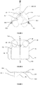
Figure 1 2 is a schematic top plan view of the device ofFigure 1 ; -
Figure 3 is a schematic bottom plan view of the device ofFigure 1 ; -
Figure 4 is a schematic top plan view of a platform as part of the device ofFigure 1 ; and -
Figure 5 is a schematic side view of the platform ofFigure 5 . -
Figures 1 to 5 show a portable prone head support device according to an exemplary embodiment. - As shown in
Figure 1 , a portable pronehead support device 10 comprises ahead support member 12 and aframe 14, thehead support member 12 providing aface aperture 16 adapted to receive a user's face in prone position, theframe 14 having atrunk 18 and abase 20, thetrunk 18 being adapted to locate thehead support member 12 at a distance from saidbase 20, characterised in that thebase 20 of theframe 14 is adapted to provide a stable engagement with a ground surface, and thetrunk 18 is adjustable in at least one plane to allow positioning of thehead support member 12 relative to a second surface elevated from said ground surface. - As shown in
Figure 2 , thehead support member 12 is a substantially c-shaped component, surrounding theface aperture 16. Theface aperture 16 is a keyhole shape, with acircular part 16a connected to anopening 16b within thehead support member 12. The forehead and the cheeks of a face of a user is supported by atop side 12a ofhead support member 12 in a prone position, whilst providing adequate space for the chin to protrude through theopening 16b and for the eyes and the nose to be observable through thecircular part 16a. - A fixing
plate 22 is mounted on anunderside 12b of thehead support member 12. The fixing plate is located approximately opposite theopening 16b opposite the portion of thetop side 12a that would support the forehead of a user. - In turn, the fixing
plate 22 is attached to a short upper section ofpost 24a. - A
hinge 26 is attached to the short upper section ofpost 24a and thehinge 26 is attached to a long lower section ofpost 24b. A user-adjustable lever 26a is provided on thehinge 26 to allow for an angle A of the hinge to be adjusted and then retained in place. The angle A provides approximately up to 180° rotation to allow for thehead support member 12 to be tilted backwards up to 90° (putting it in an upright position - although this is not likely to be required) and forwards up to 90° (putting it in a downward position - only likely to be required for storage and portability). A mid-range of movement across the 180° rotation allows for thehead support member 12 to be tilted and fine-tuned according to a user's preference. - The lower section of
post 24b is slidably engaged with an open-endedbore 28 provided within abody 30. A handledset screw 34 is provided on thebody 30 such that the screw extends through thebody 30 into thebore 28 and is adjustable to loosen or tighten against thepost 24b therein. This allows the position of the lower section ofpost 24b to be adjusted within thebore 28 in order to increase a length of the lower section ofpost 24b that is present above thebody 30. Accordingly, this mechanism provides height adjustment for thehead support member 12. - The
body 30 forms part of thebase 20 and three equally-spacedlegs 32 are rotatably mounted thereon. Eachleg 32 comprises afulcrum 32a at one end and afriction stopper 32b at an opposite free end. Thelegs 32 are able to rotate out to a splayed position in which thestoppers 32b establish a wide circular base perimeter upon contact with a ground surface. In contrast, thelegs 32 are able to rotate inwardly to a contracted position in which thelegs 32 substantially meet. - A table 40 is provided on the
device 10. The table 40 comprises aplatform 42 and a downwardly projectingsheath 44 that is located on a central axis B-B', towards atop end 42a of theplatform 42. Atriangular bracket 46 extends along the central axis from thesheath 44 to anunderside 42d of theplatform 42 in the direction of abottom end 42b. The bracket provides support to the larger part of theplatform 42a. - Two
cup holders 48 are provided in anupper face 42c of theplatform 42 towards thetop end 42a and either side of the central axis B-B'. Thecup holders 48 are provided as substantially circular apertures through theplatform 42 although it may be appreciated that these may be provided as a shallow well with a base instead. - A substantially
planar section 50 is provided as the majority of theupper face 42c of theplatform 42. Thisplanar section 50 comprises an upwardly protrudingperipheral rim 52 therearound to retain items left on the table 40. - The
sheath 44 of the table 40 is slidably engaged around the lower section ofpost 24b. Theplatform 42 is ideally oriented with theplanar section 50 located directly below theface aperture - The
device 10 is made to be portable and for this reason, it is partially collapsible and disassembled. Therefore, in use, thedevice 10, is first assembled. This is achieved by extending thelegs 32 from a contracted position to a splayed position and placing them on a ground surface. The table 40 is slidably engaged with the lower section ofpost 24b, but passing the post through thesheath 44 of the table 40 from theupper face 42c to theunderside 42d. Theset screw 34 in thebody 30 is loosened to allow for the lower section ofpost 24b (with thehinge 26, upper section ofpost 24a andhead support member 12 attached) to be slid into thebore 32a and retained by tightening theset screw 34 against thepost 24b. - Once assembled, the
device 10 is then manoeuvred into position adjacent the top end of a sunbed/ bed or lounger onto which a user intends to adopt a prone position. The height of thedevice 10 relative to the bed is adjustable by raising or lowering thepost 24b within thebore 32a and although personal preference dictates, it is generally intended that thetop side 12a of thehead support member 12 be approximately flush with the top end of the bed. Once in a lying position the user can adjust the distance of thehead support member 12 from the end of the bed for comfort, although it is generally appreciated that thehead support member 12 would be very close to the top end of such bed. Furthermore, for optimal comfort, the user can now use the user-adjustable retention lever 26a to loosen thehinge 26 and adjust the angle A of the short section ofpost 24a (and therefore, the head support member attached thereto) relative to the long section ofpost 24b and the ground surface. Once the required angle A is achieved, the user-adjustable retention lever 26a is used to tighten the hinge and prevent further movement. - The
device 10 described herein provides a portable head support that can be used on a variety of sunbeds to achieve a comfortable prone lying position. The adjustability makes it suitable to fit the comfort requirements of each user. The ability to collapse and disassemble thedevice 10 makes it easy to transport. It also tackles the issue of wet and dirty poolside floors which may damage books and electrical equipment being used, whilst making it comfortable to view such items whilst using thedevice 10. - Although a few preferred embodiments have been shown and described, it will be appreciated by those skilled in the art that various changes and modifications might be made without departing from the scope of the invention, as defined in the appended claims.
Claims (20)
- A portable prone head support device comprising a head support member and a frame, the head support member providing a face aperture adapted to receive a user's face in prone position, the frame having a trunk and a base, the trunk being adapted to locate the head support member at a distance from said base, the base of the frame being adapted to provide a stable engagement with a ground surface, and the trunk being adjustable in at least one plane to allow positioning of the head support member relative to a second surface elevated from said ground surface characterised in that the base comprises at least three legs and the legs are adapted to rotate between a splayed position, providing a wide base perimeter, and a contracted position providing a condensed substantially linear arrangement approximately in line with the post.
- The device according to claim 1, wherein the trunk is adjustable to increase or decrease the distance between the base and the head support member.
- The device according to any one of claims 1 or 2, wherein the trunk comprises a post for attachment to the head support member and the base.
- The device according to claim 2, wherein the post can be raised and lowered relative to the base.
- The device according to claim 4, wherein the base comprises a retention arrangement for the post comprising a bore through which the post passes.
- The device according to claim 5, wherein the bore is open ended and comprises a loosening and tightening means, which is in the form of a set screw with a user handle.
- The device according to claim 6, wherein the retention arrangement comprises an aperture sheath to receive said post with corresponding apertures thereon and a location means to pass through aligned apertures in said post and sheath.
- The device according to any one of claims 3 to 7, wherein the post is telescopically altered in length.
- The device according any one of claims 1 to 8, wherein to the post comprises a fixing plate at an upper end thereof for attachment to an underside of the head support member and the fixing plate is offset on the head support member one side biased towards a forehead-engaging portion of the support member..
- The device according to any one of claims 1 to 9, wherein the trunk is adjustable to incline the head support member relative to the trunk and the trunk comprises a hinge proximal to the upper end of the post.
- The device according to any one of claims 3 to 10, wherein the post comprises a short upper section for attachment to said head support member and a longer lower section for engagement with the base.
- The device according to any one of claims 10 to 11, wherein the hinge comprises at least 90° rotation about a vertical plane.
- The device according to any one of claims 10 to 12, wherein the hinge comprises a user-adjustable retention lever to hold the rotation angle selected.
- The device according to any one of claims 5 to 13, wherein the base comprises a hinge body to which each leg is rotatably attached and the hinge body comprises the bore of the retention arrangement.
- The device according to any one of claims 1 to 14, wherein the head support member is substantially C-shaped and padded.
- The device according to any one of claims 1 to 20, wherein the face aperture is substantially keyhole-shaped.
- The device according to any one of claims 1 to 16, wherein the face aperture comprises further cut-out sections to accommodate spectacle frames being worn.
- The device according to any one of claims 1 to 17, wherein the portable head support device comprises a platform located between the base and the head support member attached to the lower section of the post.
- The device according to claim 18, wherein the platform comprises a sheath for slidable engagement with the post.
- The device according to any one of claims 1 to 19, wherein the device is at least partially collapsible for portability.
Applications Claiming Priority (1)
| Application Number | Priority Date | Filing Date | Title |
|---|---|---|---|
| GB1721234.1A GB2569538B (en) | 2017-12-19 | 2017-12-19 | A portable prone head support device |
Publications (1)
| Publication Number | Publication Date |
|---|---|
| EP3549485A1 true EP3549485A1 (en) | 2019-10-09 |
Family
ID=61009213
Family Applications (1)
| Application Number | Title | Priority Date | Filing Date |
|---|---|---|---|
| EP18275184.2A Withdrawn EP3549485A1 (en) | 2017-12-19 | 2018-12-18 | Stand-alone neck support |
Country Status (2)
| Country | Link |
|---|---|
| EP (1) | EP3549485A1 (en) |
| GB (1) | GB2569538B (en) |
Citations (6)
| Publication number | Priority date | Publication date | Assignee | Title |
|---|---|---|---|---|
| DE8521460U1 (en) * | 1985-07-26 | 1985-09-19 | Harth, Victor, Dr. Med., 8600 Bamberg | Head rest in the form of a piece of furniture for couches for examining and treating patients in the prone position |
| US5970546A (en) | 1998-02-26 | 1999-10-26 | Paul Shalita | Portable headrest having a base support member with air passages for use while sunbathing |
| US6694551B1 (en) | 2002-12-30 | 2004-02-24 | Alpa, Inc. | Facial support device |
| CN202497374U (en) * | 2012-02-29 | 2012-10-24 | 西安交通大学医学院第二附属医院 | Multifunctional facial bracing frame |
| US20140312186A1 (en) * | 2013-04-19 | 2014-10-23 | Dean Howard Mech | Freestanding foldable headrest |
| CN206197534U (en) * | 2016-05-25 | 2017-05-31 | 昆明理工大学 | A kind of lactation dragging device of telescopic folding |
Family Cites Families (8)
| Publication number | Priority date | Publication date | Assignee | Title |
|---|---|---|---|---|
| US2398940A (en) * | 1942-10-19 | 1946-04-23 | Samuel R Jones | Surgical headrest |
| US5408713A (en) * | 1993-08-16 | 1995-04-25 | Westcoast Med-Assist, Inc. | Head-rest |
| US6081947A (en) * | 1998-04-13 | 2000-07-04 | Disher; Michael J. | Massage board and face rest |
| US7036168B1 (en) * | 2004-05-24 | 2006-05-02 | Kristin Knickerbocker | Portable headrest |
| US9226587B2 (en) * | 2012-03-11 | 2016-01-05 | Henry M. Halimi | Portable personal support |
| CN203183220U (en) * | 2013-03-29 | 2013-09-11 | 王瑛 | Postoperative prone position support used in ophthalmology department |
| AU2014268116A1 (en) * | 2013-05-13 | 2015-12-17 | Giuliana BARRON | Head support |
| TW201641059A (en) * | 2015-05-18 | 2016-12-01 | wu-xiong Chen | Portable multifunctional support seat |
-
2017
- 2017-12-19 GB GB1721234.1A patent/GB2569538B/en active Active
-
2018
- 2018-12-18 EP EP18275184.2A patent/EP3549485A1/en not_active Withdrawn
Patent Citations (6)
| Publication number | Priority date | Publication date | Assignee | Title |
|---|---|---|---|---|
| DE8521460U1 (en) * | 1985-07-26 | 1985-09-19 | Harth, Victor, Dr. Med., 8600 Bamberg | Head rest in the form of a piece of furniture for couches for examining and treating patients in the prone position |
| US5970546A (en) | 1998-02-26 | 1999-10-26 | Paul Shalita | Portable headrest having a base support member with air passages for use while sunbathing |
| US6694551B1 (en) | 2002-12-30 | 2004-02-24 | Alpa, Inc. | Facial support device |
| CN202497374U (en) * | 2012-02-29 | 2012-10-24 | 西安交通大学医学院第二附属医院 | Multifunctional facial bracing frame |
| US20140312186A1 (en) * | 2013-04-19 | 2014-10-23 | Dean Howard Mech | Freestanding foldable headrest |
| CN206197534U (en) * | 2016-05-25 | 2017-05-31 | 昆明理工大学 | A kind of lactation dragging device of telescopic folding |
Also Published As
| Publication number | Publication date |
|---|---|
| GB2569538A (en) | 2019-06-26 |
| GB2569538B (en) | 2022-10-19 |
| GB201721234D0 (en) | 2018-01-31 |
Similar Documents
| Publication | Publication Date | Title |
|---|---|---|
| US6151734A (en) | Head support apparatus | |
| US8864233B2 (en) | Tattoo chair | |
| US6081947A (en) | Massage board and face rest | |
| US8146615B1 (en) | Crutch device with leg support | |
| US20050109346A1 (en) | Flexing head support suspension system | |
| US20130205504A1 (en) | Surgical head support | |
| US8251455B1 (en) | Mountable fishermans chair | |
| WO2016082027A1 (en) | Head support device | |
| JP4582426B2 (en) | Patient lifting device | |
| CN108338882B (en) | Surgical mask positioning system | |
| USRE33115E (en) | Accouchement apparatus | |
| US5149033A (en) | Extremity support apparatus | |
| US20140103691A1 (en) | Handicap accessible bar stool | |
| CN205031471U (en) | Internal medicine has been nursed and has been sat frame | |
| US2878493A (en) | Therapeutic device | |
| US20100263125A1 (en) | Embedded headrest assembly for a massage table | |
| EP3549485A1 (en) | Stand-alone neck support | |
| US20050151408A1 (en) | Portable foldable leg rest | |
| US20050179230A1 (en) | Wheelchair and leg support accessory | |
| HU230016B1 (en) | Headrest for massage table | |
| KR101775573B1 (en) | Armpit support for protecting spine and preventing varicose vein | |
| US5725280A (en) | Surgeon's perch | |
| CN210447590U (en) | Ophthalmic nursing belt cleaning device | |
| KR200372603Y1 (en) | A reading desk | |
| US2850745A (en) | Vertical bed |
Legal Events
| Date | Code | Title | Description |
|---|---|---|---|
| PUAI | Public reference made under article 153(3) epc to a published international application that has entered the european phase |
Free format text: ORIGINAL CODE: 0009012 |
|
| AK | Designated contracting states |
Kind code of ref document: A1 Designated state(s): AL AT BE BG CH CY CZ DE DK EE ES FI FR GB GR HR HU IE IS IT LI LT LU LV MC MK MT NL NO PL PT RO RS SE SI SK SM TR |
|
| AX | Request for extension of the european patent |
Extension state: BA ME |
|
| STAA | Information on the status of an ep patent application or granted ep patent |
Free format text: STATUS: THE APPLICATION IS DEEMED TO BE WITHDRAWN |
|
| 18D | Application deemed to be withdrawn |
Effective date: 20200603 |