EP3549293B1 - Übertragung von kanalstatusinformationsreferenzsignalen in neuem funk - Google Patents
Übertragung von kanalstatusinformationsreferenzsignalen in neuem funk Download PDFInfo
- Publication number
- EP3549293B1 EP3549293B1 EP17876739.8A EP17876739A EP3549293B1 EP 3549293 B1 EP3549293 B1 EP 3549293B1 EP 17876739 A EP17876739 A EP 17876739A EP 3549293 B1 EP3549293 B1 EP 3549293B1
- Authority
- EP
- European Patent Office
- Prior art keywords
- csi
- rss
- configuration
- res
- signaling
- Prior art date
- Legal status (The legal status is an assumption and is not a legal conclusion. Google has not performed a legal analysis and makes no representation as to the accuracy of the status listed.)
- Active
Links
Images


Classifications
-
- H—ELECTRICITY
- H04—ELECTRIC COMMUNICATION TECHNIQUE
- H04L—TRANSMISSION OF DIGITAL INFORMATION, e.g. TELEGRAPHIC COMMUNICATION
- H04L5/00—Arrangements affording multiple use of the transmission path
- H04L5/0091—Signalling for the administration of the divided path, e.g. signalling of configuration information
- H04L5/0094—Indication of how sub-channels of the path are allocated
-
- H—ELECTRICITY
- H04—ELECTRIC COMMUNICATION TECHNIQUE
- H04B—TRANSMISSION
- H04B7/00—Radio transmission systems, i.e. using radiation field
- H04B7/02—Diversity systems; Multi-antenna system, i.e. transmission or reception using multiple antennas
- H04B7/04—Diversity systems; Multi-antenna system, i.e. transmission or reception using multiple antennas using two or more spaced independent antennas
- H04B7/06—Diversity systems; Multi-antenna system, i.e. transmission or reception using multiple antennas using two or more spaced independent antennas at the transmitting station
- H04B7/0613—Diversity systems; Multi-antenna system, i.e. transmission or reception using multiple antennas using two or more spaced independent antennas at the transmitting station using simultaneous transmission
- H04B7/0615—Diversity systems; Multi-antenna system, i.e. transmission or reception using multiple antennas using two or more spaced independent antennas at the transmitting station using simultaneous transmission of weighted versions of same signal
- H04B7/0619—Diversity systems; Multi-antenna system, i.e. transmission or reception using multiple antennas using two or more spaced independent antennas at the transmitting station using simultaneous transmission of weighted versions of same signal using feedback from receiving side
- H04B7/0621—Feedback content
- H04B7/0623—Auxiliary parameters, e.g. power control [PCB] or not acknowledged commands [NACK], used as feedback information
-
- H—ELECTRICITY
- H04—ELECTRIC COMMUNICATION TECHNIQUE
- H04B—TRANSMISSION
- H04B7/00—Radio transmission systems, i.e. using radiation field
- H04B7/02—Diversity systems; Multi-antenna system, i.e. transmission or reception using multiple antennas
- H04B7/04—Diversity systems; Multi-antenna system, i.e. transmission or reception using multiple antennas using two or more spaced independent antennas
- H04B7/06—Diversity systems; Multi-antenna system, i.e. transmission or reception using multiple antennas using two or more spaced independent antennas at the transmitting station
- H04B7/0613—Diversity systems; Multi-antenna system, i.e. transmission or reception using multiple antennas using two or more spaced independent antennas at the transmitting station using simultaneous transmission
- H04B7/0615—Diversity systems; Multi-antenna system, i.e. transmission or reception using multiple antennas using two or more spaced independent antennas at the transmitting station using simultaneous transmission of weighted versions of same signal
- H04B7/0619—Diversity systems; Multi-antenna system, i.e. transmission or reception using multiple antennas using two or more spaced independent antennas at the transmitting station using simultaneous transmission of weighted versions of same signal using feedback from receiving side
- H04B7/0621—Feedback content
- H04B7/0626—Channel coefficients, e.g. channel state information [CSI]
-
- H—ELECTRICITY
- H04—ELECTRIC COMMUNICATION TECHNIQUE
- H04L—TRANSMISSION OF DIGITAL INFORMATION, e.g. TELEGRAPHIC COMMUNICATION
- H04L1/00—Arrangements for detecting or preventing errors in the information received
- H04L1/0001—Systems modifying transmission characteristics according to link quality, e.g. power backoff
- H04L1/0023—Systems modifying transmission characteristics according to link quality, e.g. power backoff characterised by the signalling
- H04L1/0026—Transmission of channel quality indication
-
- H—ELECTRICITY
- H04—ELECTRIC COMMUNICATION TECHNIQUE
- H04L—TRANSMISSION OF DIGITAL INFORMATION, e.g. TELEGRAPHIC COMMUNICATION
- H04L1/00—Arrangements for detecting or preventing errors in the information received
- H04L1/12—Arrangements for detecting or preventing errors in the information received by using return channel
- H04L1/16—Arrangements for detecting or preventing errors in the information received by using return channel in which the return channel carries supervisory signals, e.g. repetition request signals
- H04L1/18—Automatic repetition systems, e.g. Van Duuren systems
-
- H—ELECTRICITY
- H04—ELECTRIC COMMUNICATION TECHNIQUE
- H04L—TRANSMISSION OF DIGITAL INFORMATION, e.g. TELEGRAPHIC COMMUNICATION
- H04L5/00—Arrangements affording multiple use of the transmission path
- H04L5/0001—Arrangements for dividing the transmission path
- H04L5/0003—Two-dimensional division
- H04L5/0005—Time-frequency
- H04L5/0007—Time-frequency the frequencies being orthogonal, e.g. OFDM(A) or DMT
-
- H—ELECTRICITY
- H04—ELECTRIC COMMUNICATION TECHNIQUE
- H04L—TRANSMISSION OF DIGITAL INFORMATION, e.g. TELEGRAPHIC COMMUNICATION
- H04L5/00—Arrangements affording multiple use of the transmission path
- H04L5/0001—Arrangements for dividing the transmission path
- H04L5/0014—Three-dimensional division
- H04L5/0016—Time-frequency-code
-
- H—ELECTRICITY
- H04—ELECTRIC COMMUNICATION TECHNIQUE
- H04L—TRANSMISSION OF DIGITAL INFORMATION, e.g. TELEGRAPHIC COMMUNICATION
- H04L5/00—Arrangements affording multiple use of the transmission path
- H04L5/003—Arrangements for allocating sub-channels of the transmission path
- H04L5/0048—Allocation of pilot signals, i.e. of signals known to the receiver
- H04L5/005—Allocation of pilot signals, i.e. of signals known to the receiver of common pilots, i.e. pilots destined for multiple users or terminals
-
- H—ELECTRICITY
- H04—ELECTRIC COMMUNICATION TECHNIQUE
- H04L—TRANSMISSION OF DIGITAL INFORMATION, e.g. TELEGRAPHIC COMMUNICATION
- H04L5/00—Arrangements affording multiple use of the transmission path
- H04L5/003—Arrangements for allocating sub-channels of the transmission path
- H04L5/0053—Allocation of signalling, i.e. of overhead other than pilot signals
- H04L5/0057—Physical resource allocation for CQI
Definitions
- aspects of the present disclosure related generally to wireless communications systems, and more particularly, to transmitting channel state information (CSI) reference signals (CSI-RSs) in a new radio (NR) wireless network.
- CSI channel state information
- CSI-RSs channel state information reference signals
- Wireless communication systems are widely deployed to provide various telecommunication services such as telephony, video, data, messaging, and broadcasts.
- Typical wireless communication systems may employ multiple-access technologies capable of supporting communication with multiple users by sharing available system resources (e.g., bandwidth, transmit power).
- multiple-access technologies include Long Term Evolution (LTE) systems, code division multiple access (CDMA) systems, time division multiple access (TDMA) systems, frequency division multiple access (FDMA) systems, orthogonal frequency division multiple access (OFDMA) systems, single-carrier frequency division multiple access (SC-FDMA) systems, and time division synchronous code division multiple access (TD-SCDMA) systems.
- LTE Long Term Evolution
- CDMA code division multiple access
- TDMA time division multiple access
- FDMA frequency division multiple access
- OFDMA orthogonal frequency division multiple access
- SC-FDMA single-carrier frequency division multiple access
- TD-SCDMA time division synchronous code division multiple access
- a wireless communication network may include a number of Node Bs that can support communication for a number of user equipments (UEs).
- a UE may communicate with a Node B via the downlink and uplink.
- the downlink (or forward link) refers to the communication link from the Node B to the UE
- the uplink (or reverse link) refers to the communication link from the UE to the Node B.
- NR new radio
- 3GPP Third Generation Partnership Project
- CP cyclic prefix
- DL downlink
- UL uplink
- MIMO multiple-input multiple-output
- the CSI-RS can be transmitted always with a reference numerology or with the same numerology as the PDSCH of the UE.
- New radio may refer to radios configured to operate according to a new air interface (e.g., other than Orthogonal Frequency Divisional Multiple Access (OFDMA)-based air interfaces) or fixed transport layer (e.g., other than Internet Protocol (IP)).
- NR may include Enhanced mobile broadband (eMBB) targeting wide bandwidth (e.g. 80 MHz beyond), millimeter wave (mmW) targeting high carrier frequency (e.g. 60 GHz), massive MTC (mMTC) targeting non-backward compatible MTC techniques, and mission critical targeting ultra reliable low latency communications (URLLC).
- eMBB Enhanced mobile broadband
- mmW millimeter wave
- mMTC massive MTC
- URLLC ultra reliable low latency communications
- NR cell may refer to a cell operating according to the new air interface or fixed transport layer.
- a NR Node B e.g., 5G Node B
- TRPs transmission reception points
- NR cells can be configured as access cell (ACells) or data only cells (DCells).
- the RAN e.g., a central unit or distributed unit
- DCells may be cells used for carrier aggregation or dual connectivity, but not used for initial access, cell selection/reselection, or handover. In some cases DCells may not transmit synchronization signals-in some case cases DCells may transmit SS.
- TRPs may transmit downlink signals to UEs indicating the cell type. Based on the cell type indication, the UE may communicate with the TRP. For example, the UE may determine TRPs to consider for cell selection, access, handover, and/or measurement based on the indicated cell type.
- the UE can receive measurement configuration from the RAN.
- the measurement configuration information may indicate ACells or DCells for the UE to measure.
- the UE may monitor/detect measurement reference signals from the cells based on measurement configuration information.
- the UE may blindly detect MRS.
- the UE may detect MRS based on MRS-IDs indicated from the RAN.
- the UE may report the measurement results.
- a CDMA network may implement a radio technology such as Universal Terrestrial Radio Access (UTRA), cdma2000, etc.
- UTRA includes Wideband CDMA (WCDMA) and other variants of CDMA.
- cdma2000 covers IS-2000, IS-95 and IS-856 standards.
- a TDMA network may implement a radio technology such as Global System for Mobile Communications (GSM).
- GSM Global System for Mobile Communications
- An OFDMA network may implement a radio technology such as NR (e.g.
- E-UTRA Evolved UTRA
- UMB Ultra Mobile Broadband
- IEEE 802.11 Wi-Fi
- IEEE 802.16 WiMAX
- IEEE 802.20 Flash-OFDMA
- UTRA and E-UTRA are part of Universal Mobile Telecommunication System (UMTS).
- NR is an emerging wireless communications technology under development in conjunction with the 5G Technology Forum (5GTF).
- 3GPP Long Term Evolution (LTE) and LTE-Advanced (LTE-A) are releases of UMTS that use E-UTRA.
- LTE Long Term Evolution
- LTE-A LTE-Advanced
- UTRA, E-UTRA, UMTS, LTE, LTE-A and GSM are described in documents from an organization named "3rd Generation Partnership Project" (3GPP).
- cdma2000 and UMB are described in documents from an organization named "3rd Generation Partnership Project 2" (3GPP2).
- 3GPP2 3rd Generation Partnership Project 2
- the techniques described herein may be used for the wireless networks and radio technologies mentioned above as well as other wireless networks and radio technologies.
- aspects may be described herein using terminology commonly associated with 3G and/or 4G wireless technologies, aspects of the present disclosure can be applied in other generation-based communication systems, such as 5G and later, including NR technologies.
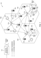
- FIG. 1 illustrates an example wireless network 100 in which aspects of the present disclosure may be performed.
- the wireless network may be new radio or 5G network.
- UEs 120 may be configured to perform the operations 900 discussed in more detail below for processing CSI-RS, in accordance with aspects of the present disclosure.
- Node B 110 may comprise a transmission reception point (TRP) configured to perform the operations 800 discussed in more detail below for transmitting CSI-RS, in accordance with aspects of the present disclosure.
- the NR network may include the central unit.
- the new radio network 100 may comprise a central unit 140.
- the UEs 120, Node B 110 (TRP), and central unit 140 may be configured to perform operations related to measurement configuration, measurement reference signal transmission, monitoring, detection, measurement, and measurement reporting, which are described in greater detail below.
- the system illustrated in FIG. 1 may be, for example, a long term evolution (LTE) network.
- the wireless network 100 may include a number of Node Bs (e.g., evolved NodeBs (eNB), 5G Node B, etc.) 110 and other network entities.
- a Node B may be a station that communicates with the UEs and may also be referred to as a base station, an access point, etc.
- a Node B and 5G Node B are other examples of stations that communicate with the UEs.
- Each Node B 110 may provide communication coverage for a particular geographic area.
- the term "cell” can refer to a coverage area of a Node B and/or a Node B subsystem serving this coverage area, depending on the context in which the term is used.
- a Node B may provide communication coverage for a macro cell, a pico cell, a femto cell, and/or other types of cell.
- a macro cell may cover a relatively large geographic area (e.g., several kilometers in radius) and may allow unrestricted access by UEs with service subscription.
- a pico cell may cover a relatively small geographic area and may allow unrestricted access by UEs with service subscription.
- a femto cell may cover a relatively small geographic area (e.g., a home) and may allow restricted access by UEs having association with the femto cell (e.g., UEs in a Closed Subscriber Group (CSG), UEs for users in the home, etc.).
- CSG Closed Subscriber Group
- a Node B for a macro cell may be referred to as a macro Node B.
- a Node B for a pico cell may be referred to as a pico Node B.
- a Node B for a femto cell may be referred to as a femto Node B or a home Node B.
- the Node Bs 110a, 110b and 110c may be macro Node Bs for the macro cells 102a, 102b and 102c, respectively.
- the Node B 110x may be a pico Node B for a pico cell 102x.
- the Node Bs 110y and 110z may be femto Node Bs for the femto cells 102y and 102z, respectively.
- a Node B may support one or multiple (e.g., three) cells.
- the wireless network 100 may also include relay stations.
- a relay station is a station that receives a transmission of data and/or other information from an upstream station (e.g., a Node B or a UE) and sends a transmission of the data and/or other information to a downstream station (e.g., a UE or a Node B).
- a relay station may also be a UE that relays transmissions for other UEs.
- a relay station 110r may communicate with the Node B 110a and a UE 120r in order to facilitate communication between the Node B 110a and the UE 120r.
- a relay station may also be referred to as a relay Node B, a relay, etc.
- the wireless network 100 may be a heterogeneous network that includes Node Bs of different types, e.g., macro Node Bs, pico Node Bs, femto Node Bs, relays, transmission reception points (TRPs), etc. These different types of Node Bs may have different transmit power levels, different coverage areas, and different impact on interference in the wireless network 100.
- Node Bs may have a high transmit power level (e.g., 20 Watts) whereas pico Node Bs, femto Node Bs and relays may have a lower transmit power level (e.g., 1 Watt).
- the wireless network 100 may support synchronous or asynchronous operation.
- the Node Bs may have similar frame timing, and transmissions from different Node Bs may be approximately aligned in time.
- the Node Bs may have different frame timing, and transmissions from different Node Bs may not be aligned in time.
- the techniques described herein may be used for both synchronous and asynchronous operation.
- a network controller 130 may couple to a set of Node Bs and provide coordination and control for these Node Bs.
- the network controller 130 may communicate with the Node Bs 110 via a backhaul.
- the Node Bs 110 may also communicate with one another, e.g., directly or indirectly via wireless or wireline backhaul.
- the UEs 120 may be dispersed throughout the wireless network 100, and each UE may be stationary or mobile.
- a UE may also be referred to as a terminal, a mobile station, a subscriber unit, a station, etc.
- a UE may be a cellular phone, a personal digital assistant (PDA), a wireless modem, a wireless communication device, a handheld device, a laptop computer, a cordless phone, a wireless local loop (WLL) station, a tablet, a netbook, a smart book, etc.
- PDA personal digital assistant
- WLL wireless local loop
- a UE may be able to communicate with macro Node Bs, pico Node Bs, femto Node Bs, relays, etc.
- a solid line with double arrows indicates desired transmissions between a UE and a serving Node B, which is a Node B designated to serve the UE on the downlink and/or uplink.
- a dashed line with double arrows indicates interfering transmissions between a UE and a Node B.
- LTE utilizes orthogonal frequency division multiplexing (OFDM) on the downlink and single-carrier frequency division multiplexing (SC-FDM) on the uplink.
- OFDM and SC-FDM partition the system bandwidth into multiple (K) orthogonal subcarriers, which are also commonly referred to as tones, bins, etc.
- K orthogonal subcarriers
- Each subcarrier may be modulated with data.
- modulation symbols are sent in the frequency domain with OFDM and in the time domain with SC-FDM.
- the spacing between adjacent subcarriers may be fixed, and the total number of subcarriers (K) may be dependent on the system bandwidth.
- the spacing of the subcarriers may be 15 kHz and the minimum resource allocation (called a 'resource block') may be 12 subcarriers (or 180 kHz). Consequently, the nominal FFT size may be equal to 128, 256, 512, 1024 or 2048 for system bandwidth of 1.25, 2.5, 5, 10 or 20 megahertz (MHz), respectively.
- the system bandwidth may also be partitioned into subbands. For example, a subband may cover 1.08 MHz (i.e., 6 resource blocks), and there may be 1, 2, 4, 8 or 16 subbands for system bandwidth of 1.25, 2.5, 5, 10 or 20 MHz, respectively.
- NR may utilize OFDM with a CP on the uplink and downlink and include support for half-duplex operation using TDD.
- a single component carrier bandwidth of 100 MHZ may be supported.
- Each radio frame may be 10 ms long and consist of 50 slots. Consequently, each slot may have a length of 0.2 ms. In alternative embodiments, each slot may have a length of 0.5 ms.
- slots may also refer to "mini-slots," which may be one to two symbol periods long.
- Each slot may indicate a link direction (i.e., DL or UL) for data transmission and the link direction for each slot may be dynamically switched.
- Each slot may include DL and/or UL data as well as DL and/or UL control data.
- Beamforming may be supported and beam direction(s) may be dynamically configured.
- MIMO transmissions with precoding may also be supported.
- NR may support a different air interface, other than an OFDM-based interface.
- NR networks may include entities such as central units, distributed units, data nodes, access nodes, and access control nodes.
- FIG. 2 shows an exemplary downlink (DL) frame structure used in a telecommunication systems (e.g., LTE).
- the transmission timeline for the downlink may be partitioned into units of radio frames.
- Each radio frame may have a predetermined duration (e.g., 10 milliseconds (ms)) and may be partitioned into 20 slots with indices of 0 through 19.
- Each slot may include L symbol periods, e.g., 7 symbol periods for a normal cyclic prefix (as shown in FIG. 2 ).
- the available time frequency resources may be partitioned into resource blocks.
- Each resource block may cover N subcarriers (e.g., 12 subcarriers) in one slot.
- the downlink control channel may carry information on uplink and downlink resource allocation for UEs and power control information for uplink channels.
- the Node B may send a physical downlink shared channel (PDSCH) in the remaining symbol periods of each slot.
- the PDSCH may carry data for UEs scheduled for data transmission on the downlink. There may also be an uplink burst at the end of the slot.
- the Node B may send the PDCCH to groups of UEs or in a unicast manner to specific UEs in certain portions of the system bandwidth.
- the Node B may send the PDSCH in a unicast manner to specific UEs in specific portions of the system bandwidth.
- a UE may be within the coverage of multiple Node Bs.
- One of these Node Bs may be selected to serve the UE.
- the serving Node B may be selected based on various criteria such as received power, path loss, signal-to-noise ratio (SNR), etc.
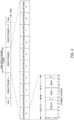
- FIG. 3 is a diagram 300 illustrating an example of an uplink (UL) frame structure in a telecommunications system (e.g., LTE).
- the available resource blocks for the UL may be partitioned into a data section and a control section.
- the control section may be formed at the two edges of the system bandwidth and may have a configurable size.
- the resource blocks in the control section may be assigned to UEs for transmission of control information.
- the data section may include all resource blocks not included in the control section.
- the UL frame structure results in the data section including contiguous subcarriers, which may allow a single UE to be assigned all of the contiguous subcarriers in the data section.
- a UE may be assigned resource blocks 310a, 310b to transmit control information to a Node B.
- the UE may also be assigned resource blocks 320a, 320b to transmit data to the Node B.
- the UE may transmit control information in a physical UL control channel (PUCCH) on the assigned resource blocks.
- the UE may transmit only data or both data and control information in a physical UL shared channel (PUSCH) on the assigned resource blocks in the data section.
- a UL transmission may hop across frequency.
- FIG. 4 illustrates example components of the base station/Node B 110 and UE 120 illustrated in FIG. 1 , which may be used to implement aspects of the present disclosure.
- One or more components of the AP 110 and UE 120 may be used to practice aspects of the present disclosure.
- antennas 452, Tx/Rx 222, processors 466, 458, 464, and/or controller/processor 480 of the UE 120 and/or antennas 434, processors 460, 420, 438, and/or controller/processor 440 of the BS 110 may be used to perform the operations described herein and illustrated with reference to FIGs. 7-8 .
- FIG. 4 shows a block diagram of a design of a base station/Node B 110 and a UE 120, which may be one of the base stations/Node Bs and one of the UEs in FIG. 1 .
- the base station 110 may be the macro Node B 110c in FIG. 1
- the UE 120 may be the UE 120y.
- the base station 110 may also be a base station of some other type.
- the base station 110 may be equipped with antennas 434a through 434t, and the UE 120 may be equipped with antennas 452a through 452r.
- a transmit processor 420 may receive data from a data source 412 and control information from a controller/processor 440.
- the control information may be for the PBCH, PCFICH, PHICH, PDCCH, etc.
- the data may be for the PDSCH, etc.
- the processor 420 may process (e.g., encode and symbol map) the data and control information to obtain data symbols and control symbols, respectively.
- the processor 420 may also generate reference symbols, e.g., for the PSS, SSS, and cell-specific reference signal.
- a transmit (TX) multiple-input multiple-output (MIMO) processor 430 may perform spatial processing (e.g., precoding) on the data symbols, the control symbols, and/or the reference symbols, if applicable, and may provide output symbol streams to the modulators (MODs) 432a through 432t.
- Each modulator 432 may process a respective output symbol stream (e.g., for OFDM, etc.) to obtain an output sample stream.
- Each modulator 432 may further process (e.g., convert to analog, amplify, filter, and upconvert) the output sample stream to obtain a downlink signal.
- Downlink signals from modulators 432a through 432t may be transmitted via the antennas 434a through 434t, respectively.
- the antennas 452a through 452r may receive the downlink signals from the base station 110 and may provide received signals to the demodulators (DEMODs) 454a through 454r, respectively.
- Each demodulator 454 may condition (e.g., filter, amplify, downconvert, and digitize) a respective received signal to obtain input samples.
- Each demodulator 454 may further process the input samples (e.g., for OFDM, etc.) to obtain received symbols.
- a MIMO detector 456 may obtain received symbols from all the demodulators 454a through 454r, perform MIMO detection on the received symbols if applicable, and provide detected symbols.
- a receive processor 458 may process (e.g., demodulate, deinterleave, and decode) the detected symbols, provide decoded data for the UE 120 to a data sink 460, and provide decoded control information to a controller/processor 480.
- a transmit processor 464 may receive and process data (e.g., for the PUSCH) from a data source 462 and control information (e.g., for the PUCCH) from the controller/processor 480.
- the transmit processor 464 may also generate reference symbols for a reference signal.
- the symbols from the transmit processor 464 may be precoded by a TX MIMO processor 466 if applicable, further processed by the demodulators 454a through 454r (e.g., for SC-FDM, etc.), and transmitted to the base station 110.
- the uplink signals from the UE 120 may be received by the antennas 434, processed by the modulators 432, detected by a MIMO detector 436 if applicable, and further processed by a receive processor 438 to obtain decoded data and control information sent by the UE 120.
- the receive processor 438 may provide the decoded data to a data sink 439 and the decoded control information to the controller/processor 440.
- the controllers/processors 440 and 480 may direct the operation at the base station 110 and the UE 120, respectively.
- the processor 440 and/or other processors and modules at the base station 110 may perform or direct, e.g., the execution of various processes for the techniques described herein.
- the processor 480 and/or other processors and modules at the UE 120 may also perform or direct, e.g., the execution of the functional blocks illustrated in FIGs. 12-14 , and/or other processes for the techniques described herein.
- the memories 442 and 482 may store data and program codes for the base station 110 and the UE 120, respectively.
- a scheduler 444 may schedule UEs for data transmission on the downlink and/or uplink.
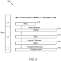
- FIG. 5 is a diagram 500 illustrating an example of a radio protocol architecture for the user and control planes in LTE.
- the radio protocol architecture for the UE and the Node B is shown with three layers: Layer 1, Layer 2, and Layer 3.
- Layer 1 (L1 layer) is the lowest layer and implements various physical layer signal processing functions.
- the L1 layer will be referred to herein as the physical layer 506.
- Layer 2 (L2 layer) 508 is above the physical layer 506 and is responsible for the link between the UE and Node B over the physical layer 506.
- the L2 layer 508 includes a media access control (MAC) sublayer 510, a radio link control (RLC) sublayer 512, and a packet data convergence protocol (PDCP) 514 sublayer, which are terminated at the Node B on the network side.
- MAC media access control
- RLC radio link control
- PDCP packet data convergence protocol
- the UE may have several upper layers above the L2 layer 508 including a network layer (e.g., IP layer) that is terminated at the PDN gateway 118 on the network side, and an application layer that is terminated at the other end of the connection (e.g., far end UE, server, etc.).
- IP layer e.g., IP layer
- the PDCP sublayer 514 provides multiplexing between different radio bearers and logical channels.
- the PDCP sublayer 514 also provides header compression for upper layer data packets to reduce radio transmission overhead, security by ciphering the data packets, and handover support for UEs between Node Bs.
- the RLC sublayer 512 provides segmentation and reassembly of upper layer data packets, retransmission of lost data packets, and reordering of data packets to compensate for out-of-order reception due to hybrid automatic repeat request (HARQ).
- HARQ hybrid automatic repeat request
- the MAC sublayer 510 provides multiplexing between logical and transport channels.
- the MAC sublayer 510 is also responsible for allocating the various radio resources (e.g., resource blocks) in one cell among the UEs.
- the MAC sublayer 510 is also responsible for HARQ operations.
- the radio protocol architecture for the UE and Node B is substantially the same for the physical layer 506 and the L2 layer 508 with the exception that there is no header compression function for the control plane.
- the control plane also includes a radio resource control (RRC) sublayer 516 in Layer 3 (L3 layer).
- RRC sublayer 516 is responsible for obtaining radio resources (i.e., radio bearers) and for configuring the lower layers using RRC signaling between the Node B and the UE.
- New radio may refer to radios configured to operate according a wireless standard, such as 5G (e.g. wireless network 100).
- NR may include Enhanced mobile broadband (eMBB) targeting wide bandwidth (e.g. 80 MHz and beyond), millimeter wave (mmW) targeting high carrier frequency (e.g. 27 GHz and higher), massive MTC (mMTC) targeting non-backward compatible MTC techniques, and mission critical targeting ultra reliable low latency communications (URLLC).
- eMBB Enhanced mobile broadband
- mmW millimeter wave
- mMTC massive MTC
- URLLC ultra reliable low latency communications
- NR cell may refer to a cell operating according in the NR network.
- a NR Node B e.g., Node B 110
- TRPs transmission and reception points
- a cell may refer to a combination of downlink (and potentially also uplink) resources.
- SI system information
- system information can be transmitted in a physical broadcast channel (PBCH) carrying a master information block (MIB).
- PBCH physical broadcast channel
- MIB master information block
- NR RAN architecture may include a central unit (CU) (e.g., central unit 140).
- the CU may be an Access node controller (ANC).
- the CU terminates backhaul interface to a RAN core network (RAN-CN) and terminates backhaul interface to one or more neighbor RAN nodes.
- the RAN may include a distributed unit that may be one or more TRPs that may be connected to one or more ANCs (not shown).
- TRPs may advertise System Information (e.g., Global TRP ID), may include PDCP/RLC/MAC functions, may comprise one or more antenna ports, may be configured to individually (dynamic selection) or jointly (joint transmission) transmit to UEs, and may serve traffic to the UE.
- System Information e.g., Global TRP ID
- PDCP/RLC/MAC functions may comprise one or more antenna ports, may be configured to individually (dynamic selection) or jointly (joint transmission) transmit to UEs, and may serve traffic to the UE.
- FIG. 6 shows another exemplary transmission timeline 600 that may be used in a TDD system in which one or more aspects of the present disclosure may be practiced.
- the timeline 600 is divided into a plurality of slots 602 or 610.
- a slot is a scheduling unit that has DL control, data, and UL control, as shown.
- a mini-slot is the smaller scheduling unit that 5G will support.
- a mini-slot can be as small as 1 or 2 OFDM symbols and can have DL control, data, and UL control.
- slots in a TDD communications system may be UL-centric or DL-centric.
- An UL-centric slot is a slot with a majority of OFDM symbols of the slot used for UL transmission(s).
- An UL-centric slot typically has a few (e.g. 2) DL symbols at the beginning, then a guard duration, then UL symbols.
- a DL-centric slot is a slot with a majority of OFDM symbols used for DL transmission.
- a DL-centric slot typically has most (e.g. 12) of the first symbols used for DL transmissions, then a guard interval, then a few (e.g., 1-2) UL symbols.
- the timeline 600 includes a plurality DL-centric slots 602 that have most symbols 604 dedicated to DL transmissions (e.g., from a BS to a UE) and a common UL burst 606 at the end with very limited resources dedicated to UL transmissions (e.g., from a UE to a BS).
- the timeline also includes a plurality of UL-centric slots 610 that each has a DL symbol 612 at the beginning of the slot, but the remaining symbols 614 of the slot are dedicated to UL transmissions.
- the UL symbols 614 may be allocated to various users (e.g., UEs) for a variety of UL transmissions (e.g., OFDM PUSCH, SC-FDM PUSCH, SC-FDM PUCCH, OFDM PUCCH).
- the DL symbols 604 of a DL slot 602 may be allocated for a variety of DL transmissions (e.g., PDCCH, PDSCH) to one or more UEs.
- DL-centric slots and UL-centric slots may occur according to a ratio configurable by the network (e.g., a network controller).
- the ratio of DL-centric slots and UL-centric slots may be of the order of 4:1, 10:1, etc., i.e., there may be significantly more DL-centric slots than UL-centric slots in many wireless communications systems.
- MIMO may be an important technology enabler for satisfying NR coverage and capacity requirements.
- the advantages of using MIMO come at the price of obtaining channel state information (CSI) at the transmission/reception point (TRP).
- the CSI has to be obtained at the TRP via UE feedback based on DL channel estimation by the UE(s), aided by CSI-RS transmitted by the TRP and processed by the UE(s).
- FIG. 7 illustrates an exemplary resource block structure 700 showing a mapping of CSI-RSs to resource elements in an LTE communications system, according to aspects of the present disclosure.
- up to 40 resource elements (REs) may be reserved for CSI-RS transmission in FDD.
- the 40 REs that may be reserved for CSI-RS transmission are shown at 702, 704, 706, 708, 710, 712, 714, 716, 718, and 720 labeled as sets A through J of REs, with 4 REs per set.
- Sets A through J are capable of supporting 10 CSI-RSs, as shown in FIG. 7 .
- the 2 CSI-RS ports may be multiplexed by size-2 orthogonal cover codes (OCC) in the time domain.
- OCC orthogonal cover codes
- a cell transmits CSI-RS using 4 CSI-RS ports
- the 4 CSI-RS ports may be multiplexed by applying size-4 OCC in both the time and the frequency domain.
- Orthogonal cover codes (OCC) provide additional orthogonality between the CSI-RS ports.
- an NR TRP may determine a configuration of CSI-RSs in resource elements, transmit an indication of the determined configuration, and transmit the CSI-RSs according to the configuration.
- a UE may obtain the indication of the determined configuration, process CSI-RSs based on the indicated configuration to determine channel state information, and report the channel state information to the TRP.
- Operation of a massive MIMO wireless communication system heavily relies on a variety of procedures and mechanisms to provide channel state information (CSI) at the transmitter for achieving high beamforming and spatial multiplexing gains.
- the TRP receiving the CSI may then use the CSI for downlink scheduling by a BS.
- the provided techniques for mapping CSI-RSs to REs may support at least 32 ports while using a smaller footprint, in terms of transmission resources, than other techniques.
- the provided techniques for mapping CSI-RSs to REs may support both beamformed and non-precoded CSI-RS.
- Power boosting of CSI-RS may improve coverage for UEs in poor coverage conditions.
- the provided techniques for mapping CSI-RSs to REs may support CSI-RS resource pooling.
- the provided techniques for mapping CSI-RSs to REs may support transmissions using self-contained slots.
- a self-contained slot is a slot in which a TRP transmits a control channel scheduling an UL transmission (e.g., a PUSCH) or a DL transmission (e.g., a PDSCH) in the same slot.
- the data transmission occurs in the same slot, and if the data transmission was a DL transmission, then a UE that received the DL transmission transmits an acknowledgment (ACK) in the same slot.
- ACK acknowledgment
- a transmission e.g., the PDCCH
- an indication that the transmission was successful e.g., the PUSCH or the ACK
- FIG. 8 illustrates example operations 800 for wireless communications by a TRP, according to aspects of the present disclosure.
- the operations 800 may be performed, for example, by BS 110 shown in FIG. 1 .
- Operations 800 begin, at block 802 by determining a configuration of channel state information reference signals (CSI-RSs), wherein the configuration indicates a set of resource elements (REs) to be used for CSI-RSs and a first mapping of CSI-RS ports to the set of REs.
- CSI-RSs channel state information reference signals
- BS 110 determines a configuration of CSI-RSs (e.g., the configuration illustrated in FIG. 10 , described below), wherein the configuration indicates a set of REs to be used for CSI-RSs and a first mapping (e.g., the mapping shown in FIG. 10 ) of CSI-RS ports to the set of REs.
- operations 800 continue with sending an indication of the configuration of the CSI-RSs.
- BS 110 sends (e.g., transmits) an indication (e.g., via radio resource control (RRC), layer 2 (L2), and/or layer 1 (L1) signaling) of the configuration of the CSI-RSs.
- RRC radio resource control
- L2 layer 2
- L1 layer 1
- Operations 800 continue, at block 806, with transmitting the CSI-RSs according to the determined configuration.
- BS 110 transmits the CSI-RSs according to the configuration determined in block 802 (e.g., the configuration illustrated in FIG. 10 , described below).
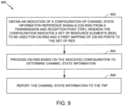
- FIG. 9 is a flowchart illustrating example operations 900 for wireless communications by a wireless node, according to aspects of the present disclosure.
- the operations 900 may be performed by, for example, a UE (e.g., UE 120).
- Operations 900 may be considered UE-side operations performed to process CSI-RS transmitted in accordance with operations 800 described above.
- Operations 900 begin, at block 902, by the wireless node obtaining an indication of a configuration of channel state information reference signals (CSI-RSs) from a transmission and reception point (TRP), wherein the configuration indicates a set of resource elements (REs) to be used for CSI-RSs and a first mapping of CSI-RS ports to the set of REs.
- CSI-RSs channel state information reference signals
- TRP transmission and reception point
- the configuration indicates a set of resource elements (REs) to be used for CSI-RSs and a first mapping of CSI-RS ports to the set of REs.
- UE 120 shown in FIG. 1 , obtains (e.g., receives via RRC, L2, and/or L1 signaling) an indication of a configuration (e.g., the configuration illustrated in FIG. 10 ) from a TRP (e.g., BS 110a, shown in FIG. 1 ), wherein the configuration indicates a set of REs to be used for CSI-RSs and a first mapping
- Operations 900 continue, at block 904, by the wireless node processing CSI-RSs based on the indicated configuration to determine channel state information.
- the UE 120 processes (e.g., measures) CSI-RSs based on the indicated configuration (from block 902) to determine channel state information.
- the UE reports the channel state information to the TRP.
- the UE 120 reports (e.g., by transmitting a CSI report) the channel state information to the TRP (e.g., BS 110a, shown in FIG. 1 ).
- Control signaling can be used to indicate one symbol (self-contained CSI-RS symbol) or more than 1 symbol with OCC and possibly some combinations of one symbol and two symbols in a slot: for example, for a 7-symbol slot, 3 pairs of CSI-RS symbols plus 1 CSI-RS symbol may be used.
- configurable orthogonal cover codes may be applied in time and/or frequency.
- the OCC configuration may be indicated via higher-layer signaling (e.g., RRC), L2 signaling (e.g., a MAC CE), L1 signaling (e.g., a DCI) and/or any combination of RRC, L2, or L1 signaling.
- scalable numerology symbols for 1-symbol CSI-RS may be used to create two virtual symbols, for example, by applying OCC in time (time domain OCC (TD-OCC)). For example, instead of transmitting one OFDM symbol with a first numerology, two OFDM symbols with a second numerology with double subcarrier spacing (SCS) and the same cyclic prefix (CP) overhead are transmitted. These two symbols can carry the CSI-RS using TD-OCC.
- TD-OCC time domain OCC
- the location (in time domain) of CSI-RS may be determined relative to the end of the DL portion, when a self-contained slot is used. For example, if one OFDM symbol with CSI-RS is used, this symbol is implicitly understood that it is the latest (e.g., last) DL symbol in the DL burst. Similarly, if two or more symbols carrying CSI-RS are used, then the last two or more latest symbols of the DL burst are being used for CSI-RS. In this example, data shall not be multiplexed with CSI-RS on the same symbols.
- a CSI-RS transmission may be self-contained in one OFDM symbol.
- a 1-symbol CSI-RS may be a self-contained CSI-RS transmitted using interleaved frequency division multiplexing (IFDM) and/or code division multiplexing (CDM).
- IFDM interleaved frequency division multiplexing
- CDM code division multiplexing
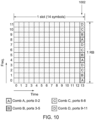
- the CSI-RS may be transmitted on uniformly distributed REs.
- the CSI-RS resources correspond to RE groups.
- Different CSI-RS ports may be separated by using different combs, labeled combs A, B, C, and D and shown at 1002, and/or using different cyclic-shifts of a common root constant amplitude zero autocorrelation (CAZAC) sequence (e.g., a Zadoff-Chu sequence).
- CAZAC constant amplitude zero autocorrelation
- Comb A corresponds to frequencies 0, 4, and 8.
- comb B corresponds to frequencies 1, 5, and 9
- comb C corresponds to frequencies 2, 6, and 10
- comb D corresponds to frequencies 3, 7, and 11.
- a series of discrete, equally spaced elements in a spectrum may be referred to as a frequency comb.
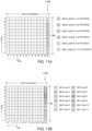
- FIGs. 11A and 11B illustrate other examples of 1-symbol CSI-RS transmission with frequency division multiplexing (FDM) and/or frequency division orthogonal cover codes (FD-OCC).
- the CSI-RS may be transmitted on a set of uniformly distributed RE groups. Each group may comprise two or more localized or distributed REs. Different CSI-RS ports may be separated by different sets of RE groups and further by applying orthogonal cover codes (OCC) to the REs in each group.
- OCC orthogonal cover codes
- FIG. 11A it can be seen that there are 6 CSI-RS configurations, A-F, with each set (e.g. set A, set B, ...
- Resource configuration set A comprises ports 0 and 1 with size-2 frequency domain orthogonal cover codes (FD-OCC2).
- Resource configuration set B comprises ports 2 and 3 with FD-OCC2.
- Resource configuration set C comprises ports 4 and 5 with FD-OCC2.
- Resource configuration set D comprises ports 6 and 7 with FD-OCC2.
- Resource configuration set E comprises ports 8 and 9 with FD-OCC2.
- Resource configuration set F comprises ports 10 and 11 with FD-OCC2.
- FIG. 11B it can be seen that there are 12 CSI-RS configurations at 1152, each CSI-RS resource or port being mapped to 1 RE.
- FIGs. 12A and 12B illustrate 2-symbol CSI-RS, with each CSI-RS transmission using a pair of OFDM symbols with TD-OCC, in accordance with aspects of the present disclosure.
- a UE can be configured to further apply orthogonal cover codes (OCC) to two OFDM symbols.
- TD-OCC may be configurable for the 2-symbol CSI-RS solution.
- the configuration can be either signaled using higher-layer signaling (e.g., RRC), L2 signaling (e.g., MAC CE), L1 signaling (e.g., DCI), and/or any combination of higher-layer signaling, L2 signaling, or L1 signaling.
- FIG. 12A illustrates an example of mapping CSI-RS with IFDM and/or CDM and TD-OCC at 1202.
- FIG. 12B illustrates an example of mapping CSI-RS with FDM and FD-OCC and/or TD-OCC at 1252.
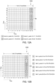
- FIGs. 13A and 13B illustrate examples of multiple 1-symbol CSI-RS transmissions in a slot, in accordance with aspects of the present disclosure.
- a UE may be configured with one or more OFDM symbols for 1-symbol CSI-RS transmission.
- a UE may be configured with CSI-RS transmission on 2 OFDM symbols; one symbol may convey CSI-RS ports 0-11, as shown at 1302, and the other symbol may convey CSI-RS ports 12-23, as shown at 1304.
- the ports may be divided into twelve sets of CSI-RS resources, while still having a first symbol convey CSI-RS ports 0-11, as shown at 1352, and another symbol conveying CSI-RS ports 12-23, as shown at 1354.
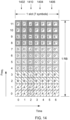
- FIG. 14 illustrates an example of a combination (e.g., a mix) of 1-symbol and 2-symbol CSI-RSs in a slot.
- a UE may be configured with one or more 1-symbol and/or 2-symbol CSI-RSs.
- a UE in case of a 7-symbol slot, a UE can be configured w/ three 2-symbol CSI-RSs with TD-OCC2, shosn at 1402, 1404, and 1406, and a 1-symbol CSI-RS 1410.
- the configuration may be signaled using higher-layer signaling (e.g., RRC), L2 signaling (e.g., MAC CE), L1 signaling (e.g., DCI), and/or any combination of higher-layer signaling, L2 signaling, and L1 signaling.
- the configuration may indicate which symbols are used for 1-symbol CSI-RS and which symbols are used for 2-symbol CSI-RS.
- a 1-symbol CSI-RS can be virtually split into 2-symbol CSI-RS with TD-OCC2.
- scaled numerology double subcarrier spacing with the same CP overhead
- SCS subcarrier spacing
- FIG. 15A illustrates an example of CSI-RS location in a self-contained slot.
- symbols carrying CSI-RS may be allocated relative to the "end" of the DL part of the slot, as shown at 1502.
- the same technique may be applied to aggregation of slots or mini-slots.
- CSI-RS and data may not be frequency division multiplexed in these symbols. If frequency division multiplexing of data and CSI-RS was supported, then data would appear in the last symbols, which would make the timeline processing and the fast-turnaround of the ACK difficult for the UE.
- TD-OCC may be used to ensure that no resources are left unused. For example, if 6 ports need to be supported, if no TD-OCC is used, then 4 ports will appear in one symbol, and 2 ports in the other symbol. Then, some resource elements may not be allowed to carry data, and therefore these resources are lost. As shown at 1502 and 1504, eight ports may be supported in a set of eight REs, both without using TD-OCC, as at 1502, and using TD-OCC, as at 1504.
- the methods disclosed herein comprise one or more steps or actions for achieving the described method.
- the method steps and/or actions may be interchanged with one another without departing from the scope of the claims.
- the order and/or use of specific steps and/or actions may be modified without departing from the scope of the claims.
- a phrase referring to "at least one of" a list of items refers to any combination of those items, including single members.
- "at least one of: a, b, or c” is intended to cover a, b, c, a-b, a-c, b-c, and a-b-c, as well as any combination with multiples of the same element (e.g., a-a, a-a-a, a-a-b, a-a-c, a-b-b, a-c-c, b-b, b-b-b, b-b-c, c-c, and c-c-c or any other ordering of a, b, and c).
- determining encompasses a wide variety of actions. For example, “determining” may include calculating, computing, processing, deriving, investigating, looking up (e.g., looking up in a table, a database or another data structure), ascertaining and the like. Also, “determining” may include receiving (e.g., receiving information), accessing (e.g., accessing data in a memory) and the like. Also, “determining” may include resolving, selecting, choosing, establishing and the like.
- the various operations of methods described above may be performed by any suitable means capable of performing the corresponding functions.
- the means may include various hardware and/or software component(s) and/or module(s), including, but not limited to a circuit, an application specific integrated circuit (ASIC), or processor.
- ASIC application specific integrated circuit
- DSP digital signal processor
- ASIC application specific integrated circuit
- FPGA field programmable gate array
- PLD programmable logic device
- a general-purpose processor may be a microprocessor, but in the alternative, the processor may be any commercially available processor, controller, microcontroller, or state machine.
- a processor may also be implemented as a combination of computing devices, e.g., a combination of a DSP and a microprocessor, a plurality of microprocessors, one or more microprocessors in conjunction with a DSP core, or any other such configuration.
- an example hardware configuration may comprise a processing system in a wireless node.
- the processing system may be implemented with a bus architecture.
- the bus may include any number of interconnecting buses and bridges depending on the specific application of the processing system and the overall design constraints.
- the bus may link together various circuits including a processor, machine-readable media, and a bus interface.
- the bus interface may be used to connect a network adapter, among other things, to the processing system via the bus.
- the network adapter may be used to implement the signal processing functions of the PHY layer.
- a user interface e.g., keypad, display, mouse, joystick, etc.
- the bus may also link various other circuits such as timing sources, peripherals, voltage regulators, power management circuits, and the like, which are well known in the art, and therefore, will not be described any further.
- the processor may be implemented with one or more general-purpose and/or special-purpose processors. Examples include microprocessors, microcontrollers, DSP processors, and other circuitry that can execute software. Those skilled in the art will recognize how best to implement the described functionality for the processing system depending on the particular application and the overall design constraints imposed on the overall system.
- the functions may be stored or transmitted over as one or more instructions or code on a computer-readable medium.
- Software shall be construed broadly to mean instructions, data, or any combination thereof, whether referred to as software, firmware, middleware, microcode, hardware description language, or otherwise.
- Computer-readable media include both computer storage media and communication media including any medium that facilitates transfer of a computer program from one place to another.
- the processor may be responsible for managing the bus and general processing, including the execution of software modules stored on the machine-readable storage media.
- a computer-readable storage medium may be coupled to a processor such that the processor can read information from, and write information to, the storage medium. In the alternative, the storage medium may be integral to the processor.
- the machine-readable media may include a transmission line, a carrier wave modulated by data, and/or a computer readable storage medium with instructions stored thereon separate from the wireless node, all of which may be accessed by the processor through the bus interface.
- the machine-readable media, or any portion thereof may be integrated into the processor, such as the case may be with cache and/or general register files.
- machine-readable storage media may include, by way of example, RAM (Random Access Memory), flash memory, ROM (Read Only Memory), PROM (Programmable Read-Only Memory), EPROM (Erasable Programmable Read-Only Memory), EEPROM (Electrically Erasable Programmable Read-Only Memory), registers, magnetic disks, optical disks, hard drives, or any other suitable storage medium, or any combination thereof.
- RAM Random Access Memory
- ROM Read Only Memory
- PROM PROM
- EPROM Erasable Programmable Read-Only Memory
- EEPROM Electrical Erasable Programmable Read-Only Memory
- registers magnetic disks, optical disks, hard drives, or any other suitable storage medium, or any combination thereof.
- the machine-readable media may be embodied in a computer-program product.
- a software module may comprise a single instruction, or many instructions, and may be distributed over several different code segments, among different programs, and across multiple storage media.
- the computer-readable media may comprise a number of software modules.
- the software modules include instructions that, when executed by an apparatus such as a processor, cause the processing system to perform various functions.
- the software modules may include a transmission module and a receiving module. Each software module may reside in a single storage device or be distributed across multiple storage devices.
- a software module may be loaded into RAM from a hard drive when a triggering event occurs.
- the processor may load some of the instructions into cache to increase access speed.
- One or more cache lines may then be loaded into a general register file for execution by the processor.
- any connection is properly termed a computer-readable medium.
- the software is transmitted from a website, server, or other remote source using a coaxial cable, fiber optic cable, twisted pair, digital subscriber line (DSL), or wireless technologies such as infrared (IR), radio, and microwave
- the coaxial cable, fiber optic cable, twisted pair, DSL, or wireless technologies such as infrared, radio, and microwave are included in the definition of medium.
- Disk and disc include compact disc (CD), laser disc, optical disc, digital versatile disc (DVD), floppy disk, and Blu-ray ® disc where disks usually reproduce data magnetically, while discs reproduce data optically with lasers.
- computer-readable media may comprise non-transitory computer-readable media (e.g., tangible media).
- computer-readable media may comprise transitory computer-readable media (e.g., a signal). Combinations of the above should also be included within the scope of computer-readable media.
- certain aspects may comprise a computer program product for performing the operations presented herein.
- a computer program product may comprise a computer-readable medium having instructions stored (and/or encoded) thereon, the instructions being executable by one or more processors to perform the operations described herein.
- instructions for determining a maximum available transmit power of the UE instructions for semi-statically configuring a first minimum guaranteed power available for uplink transmission to a first base station and a second minimum guaranteed power available for uplink transmission to a second base station, and instructions for dynamically determining a first maximum transmit power available for uplink transmission to the first base station and a second maximum transmit power available for uplink transmission to the second base station based, at least in part, on the maximum available transmit power of the UE, the first minimum guaranteed power, and the second minimum guaranteed power.
- modules and/or other appropriate means for performing the methods and techniques described herein can be downloaded and/or otherwise obtained by a user terminal and/or base station as applicable.
- a user terminal and/or base station can be coupled to a server to facilitate the transfer of means for performing the methods described herein.
- various methods described herein can be provided via storage means (e.g., RAM, ROM, a physical storage medium such as a compact disc (CD) or floppy disk, etc.), such that a user terminal and/or base station can obtain the various methods upon coupling or providing the storage means to the device.
- storage means e.g., RAM, ROM, a physical storage medium such as a compact disc (CD) or floppy disk, etc.
- CD compact disc
- floppy disk etc.
- any other suitable technique for providing the methods and techniques described herein to a device can be utilized.
Landscapes
- Engineering & Computer Science (AREA)
- Signal Processing (AREA)
- Computer Networks & Wireless Communication (AREA)
- Quality & Reliability (AREA)
- Mobile Radio Communication Systems (AREA)
Claims (15)
- Verfahren (800) für drahtlose Kommunikation durch einen Sende-Empfangs-Knoten (110), umfassend:Bestimmen (802) einer Konfiguration von Kanalzustandsinformations-Referenzsignalen, CSI-RSs, wobei die Konfiguration einen Satz von Ressourcenelementen, REs, die für CSI-RSs zu verwenden sind, und eine erste Abbildung von CSI-RS-Ports auf den Satz von REs angibt;Senden (804) einer Anzeige der Konfiguration der CSI-RSs; undÜbermitteln (806) der CSI-RS gemäß der ermittelten Konfiguration;dadurch gekennzeichnet, dass:
die Konfiguration eine Kombination aus einem orthogonalen Frequenzmultiplex-Symbol, OFDM, CSI-RS und zwei OFDM-Symbolen CSI-RS in einem Schlitz anzeigt. - Verfahren nach Anspruch 1, wobei die Konfiguration ferner orthogonale Deckungscodes, OCCs, angibt, die für die Übertragung der CSI-RS verwendet werden.
- Verfahren nach Anspruch 1, ferner umfassend:
Signalisierung der Konfiguration unter Verwendung von mindestens einem der folgenden Verfahren: Funkressourcensteuerungs-, RRC-, Signalisierung, Schicht 2-, L2-, Signalisierung, oder Schicht 1-, L1-, Signalisierung. - Verfahren nach Anspruch 1, wobei das Bestimmen der Konfiguration umfasst:Bestimmen einer Vielzahl von REs, die für eine Abwärtsstrecken-Übertragung zu einem Empfänger verwendet werden sollen; undAuswählen einer Gruppe von REs, die die zeitlich jüngsten REs der Vielzahl von REs sind, für den Satz von REs, die für die CSI-RSs verwendet werden sollen.
- Verfahren (900) für drahtlose Kommunikation durch ein Benutzergerät (120), umfassend:Empfangen (902) einer Anzeige einer Konfiguration von Kanalzustandsinformations-Referenzsignalen, CSI-RSs, von einem Sende-EmpfangsKnoten, TRP, wobei die Konfiguration einen Satz von Ressourcenelementen, REs, die für CSI-RSs zu verwenden sind, und eine erste Abbildung von CSI-RS-Ports auf den Satz von REs anzeigt;Verarbeiten (904) von CSI-RSs auf der Grundlage der angegebenen Konfiguration zur Bestimmung von Kanalzustandsinformationen; undBerichten (906) der Kanalzustandsinformationen an den TRP;dadurch gekennzeichnet, dass:
die Konfiguration eine Kombination aus einem orthogonalen Frequenzmultiplex-Symbol, OFDM, CSI-RS und zwei OFDM-Symbolen CSI-RS in einem Schlitz anzeigt. - Verfahren nach Anspruch 5, wobei die Konfiguration ferner orthogonale Abdeckungscodes, OCCs, anzeigt, die für die Übertragung der CSI-RSs verwendet werden.
- Verfahren nach Anspruch 5, ferner umfassend:
Empfang der Konfiguration unter Verwendung von mindestens einem der folgenden Verfahren: Funkressourcensteuerungs-, RRC-, Signalisierung, Schicht 2-, L2-, Signalisierung, oder Schicht 1-, L1-, Signalisierung. - Vorrichtung zur drahtlosen Kommunikation durch einen Sende-Empfangs-Knoten (110), aufweisend:Mittel zum Bestimmen einer Konfiguration von Kanalzustandsinformations-Referenzsignalen, CSI-RSs, wobei die Konfiguration einen Satz von Ressourcenelementen, REs, die für CSI-RSs zu verwenden sind, und eine erste Abbildung von CSI-RS-Ports auf den Satz von REs angibt;Mittel zum Senden einer Anzeige der Konfiguration der CSI-RSs; undMittel zum Übertragen der CSI-RS gemäß der festgelegten Konfiguration;dadurch gekennzeichnet, dass:
die Konfiguration eine Kombination aus einem orthogonalen Frequenzmultiplex-Symbol, OFDM, CSI-RS und zwei OFDM-Symbolen CSI-RS in einem Schlitz anzeigt. - Vorrichtung nach Anspruch 8, wobei die Konfiguration ferner orthogonale Deckungscodes, OCCs, anzeigt, die für die Übertragung der CSI-RSs verwendet werden.
- Vorrichtung nach Anspruch 8, ferner aufweisend:
Mittel zum Signalisieren der Konfiguration unter Verwendung von mindestens einem der folgenden Verfahren: Funkressourcensteuerung-, RRC-, Signalisierung, Schicht 2-, L2-, Signalisierung, oder Schicht 1-, L1-, Signalisierung. - Vorrichtung nach Anspruch 8, wobei das Mittel zum Bestimmen der Konfiguration aufweist:Mittel zum Bestimmen einer Vielzahl von REs, die für eine Abwärtsstrecken-Übertragung zu einem Empfänger verwendet werden sollen; undMittel zum Auswählen einer Gruppe von REs, die die zeitlich jüngsten REs der Vielzahl von REs sind, für den Satz von REs, die für die CSI-RSs zu verwenden sind.
- Vorrichtung zur drahtlosen Kommunikation durch ein Benutzergerät (120), aufweisend:Mittel zum Empfangen einer Anzeige einer Konfiguration von Kanalzustandsinformations-Referenzsignalen, CSI-RS, von einem Sende-Empfangs-Knoten, TRP, wobei die Konfiguration einen Satz von Ressourcenelementen, REs, die für CSI-RSs zu verwenden sind, und eine erste Abbildung von CSI-RS-Ports auf den Satz von REs anzeigt;Mittel zum Verarbeiten von CSI-RSs auf der Grundlage der angegebenen Konfiguration zur Bestimmung von Kanalzustandsinformationen; undMittel zum Berichten der Kanalzustandsinformationen an den TRPdadurch gekennzeichnet, dass:
die Konfiguration eine Kombination aus einem orthogonalen Frequenzmultiplex-Symbol, OFDM, CSI-RS und zwei OFDM-Symbolen CSI-RS in einem Schlitz anzeigt. - Vorrichtung nach Anspruch 12, wobei die Konfiguration ferner orthogonale Deckungscodes, OCCs, anzeigt, die für die Übertragung der CSI-RSs verwendet werden.
- Vorrichtung nach Anspruch 12, ferner aufweisend:
Mittel zum Empfangen der Konfiguration unter Verwendung von mindestens einem der folgenden Verfahren: Funkressourcensteuerungs-, RRC-, Signalisierung, Schicht 2-, L2-, Signalisierung, oder Schicht 1-, L1-Signalisierung. - Computerprogramm mit Anweisungen zur Durchführung des Verfahrens nach einem der Ansprüche 1 bis 4 oder 5 bis 7, wenn es von mindestens einem Prozessor ausgeführt wird.
Applications Claiming Priority (2)
| Application Number | Priority Date | Filing Date | Title |
|---|---|---|---|
| PCT/CN2016/108346 WO2018098802A1 (en) | 2016-12-02 | 2016-12-02 | Transmitting channel state information reference signals in new radio |
| PCT/CN2017/114342 WO2018099481A1 (en) | 2016-12-02 | 2017-12-02 | Transmitting channel state information reference signals in new radio |
Publications (3)
| Publication Number | Publication Date |
|---|---|
| EP3549293A1 EP3549293A1 (de) | 2019-10-09 |
| EP3549293A4 EP3549293A4 (de) | 2020-07-08 |
| EP3549293B1 true EP3549293B1 (de) | 2025-06-25 |
Family
ID=62240992
Family Applications (1)
| Application Number | Title | Priority Date | Filing Date |
|---|---|---|---|
| EP17876739.8A Active EP3549293B1 (de) | 2016-12-02 | 2017-12-02 | Übertragung von kanalstatusinformationsreferenzsignalen in neuem funk |
Country Status (7)
| Country | Link |
|---|---|
| US (2) | US11716184B2 (de) |
| EP (1) | EP3549293B1 (de) |
| KR (2) | KR102580478B1 (de) |
| CN (1) | CN110024317B (de) |
| AU (1) | AU2017368708B2 (de) |
| BR (1) | BR112019010660A2 (de) |
| WO (2) | WO2018098802A1 (de) |
Families Citing this family (14)
| Publication number | Priority date | Publication date | Assignee | Title |
|---|---|---|---|---|
| CN107733829B (zh) * | 2016-08-12 | 2021-11-02 | 大唐移动通信设备有限公司 | 一种发送和检测同步信号的方法、设备 |
| WO2018098802A1 (en) | 2016-12-02 | 2018-06-07 | Qualcomm Incorporated | Transmitting channel state information reference signals in new radio |
| US11949613B2 (en) * | 2018-08-10 | 2024-04-02 | Apple Inc. | Scheduling for new radio in unlicensed spectrum (NR-U) |
| US10700896B2 (en) | 2018-11-09 | 2020-06-30 | Samsung Electronics Co., Ltd. | Systems and methods for time domain layer separation in orthogonal frequency division multiplexing-based receivers |
| WO2020167081A1 (ko) * | 2019-02-15 | 2020-08-20 | 삼성전자 주식회사 | 밀리미터파 무선 통신 시스템에서 기준 신호 송수신 방법 및 장치 |
| CN110677912B (zh) * | 2019-09-26 | 2023-08-15 | 北京紫光展锐通信技术有限公司 | 信息发送方法及装置、信息接收方法及装置 |
| US20240097762A1 (en) * | 2020-02-06 | 2024-03-21 | Mediatek Singapore Pte. Ltd. | Method and apparatus for channel state information reporting |
| EP4104581A4 (de) * | 2020-02-14 | 2023-11-15 | Qualcomm Incorporated | Gemeinsame anschlussauswahl für mehrere sende- und empfangspunkte |
| WO2021161271A1 (en) * | 2020-02-14 | 2021-08-19 | Telefonaktiebolaget Lm Ericsson (Publ) | Methods for csi-rs transmission |
| EP4211834B1 (de) * | 2020-10-16 | 2025-07-16 | Apple Inc. | Adaptive anwendungen von orthogonalen deckcodes auf ressourcenelementen für drahtlose kommunikationssysteme |
| CN116918417A (zh) * | 2021-02-25 | 2023-10-20 | 华为技术有限公司 | 使用具有频域偏移的短参考符号的方法和装置 |
| US11716745B1 (en) * | 2021-06-16 | 2023-08-01 | T-Mobile Innovations Llc | Scheduler systems and methods |
| US12438752B2 (en) * | 2021-12-17 | 2025-10-07 | Intel Corporation | Methods and devices for joint processing in massive MIMO systems |
| CN120570048A (zh) * | 2023-11-20 | 2025-08-29 | 北京小米移动软件有限公司 | Csi-rs资源处理方法、通信设备及存储介质 |
Family Cites Families (35)
| Publication number | Priority date | Publication date | Assignee | Title |
|---|---|---|---|---|
| CN101873615A (zh) | 2009-04-27 | 2010-10-27 | 松下电器产业株式会社 | 无线通信系统及其下行链路接收功率检测方法 |
| KR101769368B1 (ko) | 2009-08-14 | 2017-08-30 | 엘지전자 주식회사 | 다중 안테나를 지원하는 무선 통신 시스템에서 하향링크 참조신호를 전송하는 방법 및 장치 |
| AU2010298845B8 (en) | 2009-09-27 | 2014-02-27 | Lg Electronics Inc. | Method and apparatus for transmitting reference signal in wireless communication system |
| KR101740221B1 (ko) * | 2010-01-18 | 2017-05-29 | 주식회사 골드피크이노베이션즈 | 채널상태정보-기준신호 할당 방법 및 장치 |
| KR101790505B1 (ko) | 2010-06-01 | 2017-11-21 | 주식회사 골드피크이노베이션즈 | 서브프레임 구성에 따른 채널상태정보-기준신호 할당 장치 및 방법 |
| CN102972074A (zh) * | 2010-06-16 | 2013-03-13 | 爱立信(中国)通信有限公司 | 用于传送和解码参考信号的方法和装置 |
| CN101924610B (zh) * | 2010-08-02 | 2012-12-26 | 西安电子科技大学 | Lte-a系统中信道状态信息参考信号csi-rs的设计与分配方法 |
| CN102869105B (zh) * | 2011-07-07 | 2016-03-30 | 华为技术有限公司 | 一种配置参考信号的方法、UE及eNB |
| KR20130017936A (ko) * | 2011-08-12 | 2013-02-20 | 주식회사 팬택 | 전송단, 전송단의 채널 상태 정보 기준 신호 구성 시그널링 방법, 단말, 및 단말의 채널 상태 정보 보고 방법 |
| KR102026732B1 (ko) * | 2011-08-16 | 2019-09-30 | 엘지전자 주식회사 | 무선 통신 시스템에서 기지국이 하향링크 제어 채널을 다중화하는 방법 및 이를 위한 장치 |
| US9363056B2 (en) * | 2011-09-28 | 2016-06-07 | Lg Electronics Inc. | Method and apparatus for setting plurality of reference signal configurations in wireless communication system |
| CN107872266A (zh) | 2011-09-30 | 2018-04-03 | 华为技术有限公司 | 干扰测量指示方法和干扰测量方法及相关设备和通信系统 |
| JP6238981B2 (ja) * | 2012-07-12 | 2017-11-29 | エルジー エレクトロニクス インコーポレイティド | 無線接続システムにおいてアンテナポート向け参照信号送信方法 |
| WO2014110837A1 (zh) * | 2013-01-21 | 2014-07-24 | 富士通株式会社 | 信道状态信息参考信号的传输方法、基站、终端、系统、机器可读程序和存储有机器可读程序的存储介质 |
| CN104038320B (zh) * | 2013-03-04 | 2019-03-01 | 中兴通讯股份有限公司 | 资源映射、接收方法及装置、信令通知、获取方法及装置 |
| WO2014166052A1 (en) | 2013-04-09 | 2014-10-16 | Panasonic Intellectual Property Corporation Of America | Method of mapping csi-rs ports to resource blocks, base station and user equipment |
| CN105191192B (zh) * | 2013-05-09 | 2018-04-20 | Lg 电子株式会社 | 接收用于检测小尺寸小区的搜索信号的方法 |
| US10057004B2 (en) | 2013-12-11 | 2018-08-21 | Zte Wistron Telecom Ab | CSI-RS based cell discovery signal |
| US9872242B2 (en) * | 2014-01-31 | 2018-01-16 | Qualcomm Incorporated | Joint transmission of CSI-RS for channel state feedback and transmission point selection |
| US20160094326A1 (en) * | 2014-09-26 | 2016-03-31 | Electronics And Telecommunications Research Institute | Method and apparatus for transmitting channel state information reference signal |
| US9900198B2 (en) * | 2015-02-20 | 2018-02-20 | Samsung Electronics Co., Ltd. | Channel-state-information reference signals for advanced wireless systems |
| CN106160826A (zh) * | 2015-04-20 | 2016-11-23 | 中国移动通信集团公司 | Csi-rs配置及csi反馈方法、装置和相关设备 |
| PL3758250T3 (pl) * | 2015-05-14 | 2024-07-22 | Telefonaktiebolaget Lm Ericsson (Publ) | Konfigurowanie sygnałów referencyjnych pomiaru dla MIMO |
| US11218261B2 (en) * | 2015-06-01 | 2022-01-04 | Qualcomm Incorporated | Channel state information reference signals in contention-based spectrum |
| CN107852724A (zh) * | 2015-08-14 | 2018-03-27 | 株式会社Ntt都科摩 | 无线基站、用户终端以及无线通信方法 |
| US11044120B2 (en) * | 2015-11-03 | 2021-06-22 | Apple Inc. | Antenna port multiplexing |
| CN109076505B (zh) * | 2016-03-30 | 2024-08-06 | 日本电气株式会社 | 用于传输和接收参考信号的方法和装置 |
| KR20170112945A (ko) * | 2016-04-01 | 2017-10-12 | 삼성전자주식회사 | 이동통신 시스템에서 기기 간 통신과 셀룰라 통신의 공존 방법 및 장치 |
| KR102402529B1 (ko) * | 2016-05-13 | 2022-05-27 | 텔레호낙티에볼라게트 엘엠 에릭슨(피유비엘) | 감소된 밀도 csi-rs를 위한 메커니즘들 |
| KR102455240B1 (ko) * | 2016-08-18 | 2022-10-17 | 삼성전자 주식회사 | 무선 통신 시스템에서 상향링크 제어 정보를 송수신하는 방법 및 장치 |
| US10405353B2 (en) * | 2016-09-23 | 2019-09-03 | Samsung Electronics Co., Ltd. | Method and apparatus for random access in wireless systems |
| EP3520303B1 (de) * | 2016-09-28 | 2021-01-13 | NTT DoCoMo, Inc. | Drahtloskommunikationsverfahren zur übertragung einer referenzsignalressourcenanzeige |
| WO2018098802A1 (en) | 2016-12-02 | 2018-06-07 | Qualcomm Incorporated | Transmitting channel state information reference signals in new radio |
| EP4734393A1 (de) * | 2018-02-15 | 2026-04-29 | Ofinno, LLC | Strahlausfallbericht |
| US12395996B2 (en) * | 2020-07-28 | 2025-08-19 | Comcast Cable Communications, Llc | Control channel repetition using multiple coresets |
-
2016
- 2016-12-02 WO PCT/CN2016/108346 patent/WO2018098802A1/en not_active Ceased
-
2017
- 2017-12-02 US US16/466,697 patent/US11716184B2/en active Active
- 2017-12-02 WO PCT/CN2017/114342 patent/WO2018099481A1/en not_active Ceased
- 2017-12-02 KR KR1020197015671A patent/KR102580478B1/ko active Active
- 2017-12-02 BR BR112019010660-0A patent/BR112019010660A2/pt active IP Right Grant
- 2017-12-02 KR KR1020237031669A patent/KR102780812B1/ko active Active
- 2017-12-02 CN CN201780074543.XA patent/CN110024317B/zh active Active
- 2017-12-02 AU AU2017368708A patent/AU2017368708B2/en active Active
- 2017-12-02 EP EP17876739.8A patent/EP3549293B1/de active Active
-
2023
- 2023-06-06 US US18/330,050 patent/US12081478B2/en active Active
Also Published As
| Publication number | Publication date |
|---|---|
| BR112019010660A2 (pt) | 2019-10-01 |
| KR102580478B1 (ko) | 2023-09-19 |
| EP3549293A4 (de) | 2020-07-08 |
| EP3549293A1 (de) | 2019-10-09 |
| CN110024317B (zh) | 2022-02-01 |
| AU2017368708B2 (en) | 2022-06-09 |
| US11716184B2 (en) | 2023-08-01 |
| CN110024317A (zh) | 2019-07-16 |
| KR102780812B1 (ko) | 2025-03-12 |
| AU2017368708A1 (en) | 2019-05-02 |
| KR20190088990A (ko) | 2019-07-29 |
| US20230403113A1 (en) | 2023-12-14 |
| US12081478B2 (en) | 2024-09-03 |
| US20190342042A1 (en) | 2019-11-07 |
| WO2018098802A1 (en) | 2018-06-07 |
| WO2018099481A1 (en) | 2018-06-07 |
| KR20230140596A (ko) | 2023-10-06 |
Similar Documents
| Publication | Publication Date | Title |
|---|---|---|
| US12081478B2 (en) | Transmitting channel state information reference signals in new radio | |
| US10938519B2 (en) | Resource (RE) mapping rule for uplink control information (UCI) piggyback on physical uplink shared channel (PUSCH) | |
| EP3602916B1 (de) | Steuerungsressourcensatz für einzelträgerwellenform | |
| US10419171B2 (en) | Flexible guard band for heterogeneous symbol lengths/subcarrier spacing | |
| US11212032B2 (en) | Partial/full overlapping of multiple PDSCHs for non-ideal backhaul and associated rate matching of DMRS ports | |
| EP3516780A1 (de) | Techniken zur bestimmung der uplink-vorcodierungsmatrix für ein benutzergerät | |
| CN109691004B (zh) | 无线网络中的一个或多个上行链路导频时隙中的灵活的数据和/或参考信号调度 | |
| US20220183001A9 (en) | Physical uplink control channel scheduling for ack-nack feedback in multi-transmission/reception point non-coherent joint transmissions | |
| US11425695B2 (en) | Transmission of a common control in a beamforming system | |
| WO2019104552A1 (en) | Example uplink control information (uci) layer mapping | |
| US11134474B2 (en) | Multi-user multiple input multiple output operation with heterogeneous numerology systems | |
| HK40026635B (en) | Resource mapping rule for uplink control information piggyback on physical uplink shared channel |
Legal Events
| Date | Code | Title | Description |
|---|---|---|---|
| STAA | Information on the status of an ep patent application or granted ep patent |
Free format text: STATUS: THE INTERNATIONAL PUBLICATION HAS BEEN MADE |
|
| PUAI | Public reference made under article 153(3) epc to a published international application that has entered the european phase |
Free format text: ORIGINAL CODE: 0009012 |
|
| STAA | Information on the status of an ep patent application or granted ep patent |
Free format text: STATUS: REQUEST FOR EXAMINATION WAS MADE |
|
| 17P | Request for examination filed |
Effective date: 20190411 |
|
| AK | Designated contracting states |
Kind code of ref document: A1 Designated state(s): AL AT BE BG CH CY CZ DE DK EE ES FI FR GB GR HR HU IE IS IT LI LT LU LV MC MK MT NL NO PL PT RO RS SE SI SK SM TR |
|
| AX | Request for extension of the european patent |
Extension state: BA ME |
|
| DAV | Request for validation of the european patent (deleted) | ||
| DAX | Request for extension of the european patent (deleted) | ||
| A4 | Supplementary search report drawn up and despatched |
Effective date: 20200609 |
|
| RIC1 | Information provided on ipc code assigned before grant |
Ipc: H04L 1/06 20060101AFI20200604BHEP |
|
| STAA | Information on the status of an ep patent application or granted ep patent |
Free format text: STATUS: EXAMINATION IS IN PROGRESS |
|
| 17Q | First examination report despatched |
Effective date: 20220530 |
|
| GRAP | Despatch of communication of intention to grant a patent |
Free format text: ORIGINAL CODE: EPIDOSNIGR1 |
|
| STAA | Information on the status of an ep patent application or granted ep patent |
Free format text: STATUS: GRANT OF PATENT IS INTENDED |
|
| INTG | Intention to grant announced |
Effective date: 20250129 |
|
| GRAS | Grant fee paid |
Free format text: ORIGINAL CODE: EPIDOSNIGR3 |
|
| GRAA | (expected) grant |
Free format text: ORIGINAL CODE: 0009210 |
|
| STAA | Information on the status of an ep patent application or granted ep patent |
Free format text: STATUS: THE PATENT HAS BEEN GRANTED |
|
| AK | Designated contracting states |
Kind code of ref document: B1 Designated state(s): AL AT BE BG CH CY CZ DE DK EE ES FI FR GB GR HR HU IE IS IT LI LT LU LV MC MK MT NL NO PL PT RO RS SE SI SK SM TR |
|
| REG | Reference to a national code |
Ref country code: GB Ref legal event code: FG4D |
|
| REG | Reference to a national code |
Ref country code: CH Ref legal event code: EP |
|
| REG | Reference to a national code |
Ref country code: DE Ref legal event code: R096 Ref document number: 602017090188 Country of ref document: DE |
|
| REG | Reference to a national code |
Ref country code: CH Ref legal event code: EP |
|
| REG | Reference to a national code |
Ref country code: IE Ref legal event code: FG4D |
|
| PG25 | Lapsed in a contracting state [announced via postgrant information from national office to epo] |
Ref country code: FI Free format text: LAPSE BECAUSE OF FAILURE TO SUBMIT A TRANSLATION OF THE DESCRIPTION OR TO PAY THE FEE WITHIN THE PRESCRIBED TIME-LIMIT Effective date: 20250625 |
|
| REG | Reference to a national code |
Ref country code: LT Ref legal event code: MG9D |
|
| PG25 | Lapsed in a contracting state [announced via postgrant information from national office to epo] |
Ref country code: GR Free format text: LAPSE BECAUSE OF FAILURE TO SUBMIT A TRANSLATION OF THE DESCRIPTION OR TO PAY THE FEE WITHIN THE PRESCRIBED TIME-LIMIT Effective date: 20250926 Ref country code: NO Free format text: LAPSE BECAUSE OF FAILURE TO SUBMIT A TRANSLATION OF THE DESCRIPTION OR TO PAY THE FEE WITHIN THE PRESCRIBED TIME-LIMIT Effective date: 20250925 |
|
| PG25 | Lapsed in a contracting state [announced via postgrant information from national office to epo] |
Ref country code: BG Free format text: LAPSE BECAUSE OF FAILURE TO SUBMIT A TRANSLATION OF THE DESCRIPTION OR TO PAY THE FEE WITHIN THE PRESCRIBED TIME-LIMIT Effective date: 20250625 |
|
| PG25 | Lapsed in a contracting state [announced via postgrant information from national office to epo] |
Ref country code: HR Free format text: LAPSE BECAUSE OF FAILURE TO SUBMIT A TRANSLATION OF THE DESCRIPTION OR TO PAY THE FEE WITHIN THE PRESCRIBED TIME-LIMIT Effective date: 20250625 |
|
| PG25 | Lapsed in a contracting state [announced via postgrant information from national office to epo] |
Ref country code: RS Free format text: LAPSE BECAUSE OF FAILURE TO SUBMIT A TRANSLATION OF THE DESCRIPTION OR TO PAY THE FEE WITHIN THE PRESCRIBED TIME-LIMIT Effective date: 20250925 |
|
| PG25 | Lapsed in a contracting state [announced via postgrant information from national office to epo] |
Ref country code: LV Free format text: LAPSE BECAUSE OF FAILURE TO SUBMIT A TRANSLATION OF THE DESCRIPTION OR TO PAY THE FEE WITHIN THE PRESCRIBED TIME-LIMIT Effective date: 20250625 |
|
| REG | Reference to a national code |
Ref country code: NL Ref legal event code: MP Effective date: 20250625 |
|
| PG25 | Lapsed in a contracting state [announced via postgrant information from national office to epo] |
Ref country code: NL Free format text: LAPSE BECAUSE OF FAILURE TO SUBMIT A TRANSLATION OF THE DESCRIPTION OR TO PAY THE FEE WITHIN THE PRESCRIBED TIME-LIMIT Effective date: 20250625 |
|
| PG25 | Lapsed in a contracting state [announced via postgrant information from national office to epo] |
Ref country code: PT Free format text: LAPSE BECAUSE OF FAILURE TO SUBMIT A TRANSLATION OF THE DESCRIPTION OR TO PAY THE FEE WITHIN THE PRESCRIBED TIME-LIMIT Effective date: 20251027 |
|
| REG | Reference to a national code |
Ref country code: AT Ref legal event code: MK05 Ref document number: 1807712 Country of ref document: AT Kind code of ref document: T Effective date: 20250625 |
|
| PG25 | Lapsed in a contracting state [announced via postgrant information from national office to epo] |
Ref country code: IS Free format text: LAPSE BECAUSE OF FAILURE TO SUBMIT A TRANSLATION OF THE DESCRIPTION OR TO PAY THE FEE WITHIN THE PRESCRIBED TIME-LIMIT Effective date: 20251025 |
|
| PGFP | Annual fee paid to national office [announced via postgrant information from national office to epo] |
Ref country code: DE Payment date: 20251118 Year of fee payment: 9 |
|
| PGFP | Annual fee paid to national office [announced via postgrant information from national office to epo] |
Ref country code: GB Payment date: 20251113 Year of fee payment: 9 |
|
| PG25 | Lapsed in a contracting state [announced via postgrant information from national office to epo] |
Ref country code: AT Free format text: LAPSE BECAUSE OF FAILURE TO SUBMIT A TRANSLATION OF THE DESCRIPTION OR TO PAY THE FEE WITHIN THE PRESCRIBED TIME-LIMIT Effective date: 20250625 Ref country code: SM Free format text: LAPSE BECAUSE OF FAILURE TO SUBMIT A TRANSLATION OF THE DESCRIPTION OR TO PAY THE FEE WITHIN THE PRESCRIBED TIME-LIMIT Effective date: 20250625 |
|
| PGFP | Annual fee paid to national office [announced via postgrant information from national office to epo] |
Ref country code: FR Payment date: 20251111 Year of fee payment: 9 |
|
| PG25 | Lapsed in a contracting state [announced via postgrant information from national office to epo] |
Ref country code: CZ Free format text: LAPSE BECAUSE OF FAILURE TO SUBMIT A TRANSLATION OF THE DESCRIPTION OR TO PAY THE FEE WITHIN THE PRESCRIBED TIME-LIMIT Effective date: 20250625 |
|
| PG25 | Lapsed in a contracting state [announced via postgrant information from national office to epo] |
Ref country code: PL Free format text: LAPSE BECAUSE OF FAILURE TO SUBMIT A TRANSLATION OF THE DESCRIPTION OR TO PAY THE FEE WITHIN THE PRESCRIBED TIME-LIMIT Effective date: 20250625 |
|
| PG25 | Lapsed in a contracting state [announced via postgrant information from national office to epo] |
Ref country code: EE Free format text: LAPSE BECAUSE OF FAILURE TO SUBMIT A TRANSLATION OF THE DESCRIPTION OR TO PAY THE FEE WITHIN THE PRESCRIBED TIME-LIMIT Effective date: 20250625 |
|
| PG25 | Lapsed in a contracting state [announced via postgrant information from national office to epo] |
Ref country code: SK Free format text: LAPSE BECAUSE OF FAILURE TO SUBMIT A TRANSLATION OF THE DESCRIPTION OR TO PAY THE FEE WITHIN THE PRESCRIBED TIME-LIMIT Effective date: 20250625 |
|
| PG25 | Lapsed in a contracting state [announced via postgrant information from national office to epo] |
Ref country code: ES Free format text: LAPSE BECAUSE OF FAILURE TO SUBMIT A TRANSLATION OF THE DESCRIPTION OR TO PAY THE FEE WITHIN THE PRESCRIBED TIME-LIMIT Effective date: 20250625 |
|
| PG25 | Lapsed in a contracting state [announced via postgrant information from national office to epo] |
Ref country code: RO Free format text: LAPSE BECAUSE OF FAILURE TO SUBMIT A TRANSLATION OF THE DESCRIPTION OR TO PAY THE FEE WITHIN THE PRESCRIBED TIME-LIMIT Effective date: 20250625 |
|
| PG25 | Lapsed in a contracting state [announced via postgrant information from national office to epo] |
Ref country code: DK Free format text: LAPSE BECAUSE OF FAILURE TO SUBMIT A TRANSLATION OF THE DESCRIPTION OR TO PAY THE FEE WITHIN THE PRESCRIBED TIME-LIMIT Effective date: 20250625 |
|
| PG25 | Lapsed in a contracting state [announced via postgrant information from national office to epo] |
Ref country code: IT Free format text: LAPSE BECAUSE OF FAILURE TO SUBMIT A TRANSLATION OF THE DESCRIPTION OR TO PAY THE FEE WITHIN THE PRESCRIBED TIME-LIMIT Effective date: 20250625 |