EP3549215B1 - Aufhängungseinheit - Google Patents
Aufhängungseinheit Download PDFInfo
- Publication number
- EP3549215B1 EP3549215B1 EP17835488.2A EP17835488A EP3549215B1 EP 3549215 B1 EP3549215 B1 EP 3549215B1 EP 17835488 A EP17835488 A EP 17835488A EP 3549215 B1 EP3549215 B1 EP 3549215B1
- Authority
- EP
- European Patent Office
- Prior art keywords
- support member
- securing
- strip
- suspension assembly
- latch
- Prior art date
- Legal status (The legal status is an assumption and is not a legal conclusion. Google has not performed a legal analysis and makes no representation as to the accuracy of the status listed.)
- Active
Links
- 239000000725 suspension Substances 0.000 title claims description 49
- 230000015572 biosynthetic process Effects 0.000 claims description 42
- 238000003780 insertion Methods 0.000 claims description 16
- 230000037431 insertion Effects 0.000 claims description 16
- 238000005755 formation reaction Methods 0.000 description 37
- 230000000712 assembly Effects 0.000 description 2
- 238000000429 assembly Methods 0.000 description 2
- 238000005452 bending Methods 0.000 description 2
- 230000006835 compression Effects 0.000 description 2
- 238000007906 compression Methods 0.000 description 2
- 239000000463 material Substances 0.000 description 2
- 239000007769 metal material Substances 0.000 description 2
- 230000000694 effects Effects 0.000 description 1
- 238000009434 installation Methods 0.000 description 1
- 238000000034 method Methods 0.000 description 1
- 238000012856 packing Methods 0.000 description 1
- 230000002787 reinforcement Effects 0.000 description 1
Images


Classifications
-
- H—ELECTRICITY
- H02—GENERATION; CONVERSION OR DISTRIBUTION OF ELECTRIC POWER
- H02G—INSTALLATION OF ELECTRIC CABLES OR LINES, OR OF COMBINED OPTICAL AND ELECTRIC CABLES OR LINES
- H02G3/00—Installations of electric cables or lines or protective tubing therefor in or on buildings, equivalent structures or vehicles
- H02G3/26—Installations of cables, lines, or separate protective tubing therefor directly on or in walls, ceilings, or floors
- H02G3/263—Installation, e.g. suspension, of conduit channels or other supports
-
- F—MECHANICAL ENGINEERING; LIGHTING; HEATING; WEAPONS; BLASTING
- F16—ENGINEERING ELEMENTS AND UNITS; GENERAL MEASURES FOR PRODUCING AND MAINTAINING EFFECTIVE FUNCTIONING OF MACHINES OR INSTALLATIONS; THERMAL INSULATION IN GENERAL
- F16L—PIPES; JOINTS OR FITTINGS FOR PIPES; SUPPORTS FOR PIPES, CABLES OR PROTECTIVE TUBING; MEANS FOR THERMAL INSULATION IN GENERAL
- F16L3/00—Supports for pipes, cables or protective tubing, e.g. hangers, holders, clamps, cleats, clips, brackets
- F16L3/22—Supports for pipes, cables or protective tubing, e.g. hangers, holders, clamps, cleats, clips, brackets specially adapted for supporting a number of parallel pipes at intervals
- F16L3/223—Supports for pipes, cables or protective tubing, e.g. hangers, holders, clamps, cleats, clips, brackets specially adapted for supporting a number of parallel pipes at intervals each support having one transverse base for supporting the pipes
- F16L3/2235—Supports for pipes, cables or protective tubing, e.g. hangers, holders, clamps, cleats, clips, brackets specially adapted for supporting a number of parallel pipes at intervals each support having one transverse base for supporting the pipes each pipe being supported by a common element fastened to the base
-
- F—MECHANICAL ENGINEERING; LIGHTING; HEATING; WEAPONS; BLASTING
- F16—ENGINEERING ELEMENTS AND UNITS; GENERAL MEASURES FOR PRODUCING AND MAINTAINING EFFECTIVE FUNCTIONING OF MACHINES OR INSTALLATIONS; THERMAL INSULATION IN GENERAL
- F16L—PIPES; JOINTS OR FITTINGS FOR PIPES; SUPPORTS FOR PIPES, CABLES OR PROTECTIVE TUBING; MEANS FOR THERMAL INSULATION IN GENERAL
- F16L3/00—Supports for pipes, cables or protective tubing, e.g. hangers, holders, clamps, cleats, clips, brackets
- F16L3/22—Supports for pipes, cables or protective tubing, e.g. hangers, holders, clamps, cleats, clips, brackets specially adapted for supporting a number of parallel pipes at intervals
- F16L3/222—Supports for pipes, cables or protective tubing, e.g. hangers, holders, clamps, cleats, clips, brackets specially adapted for supporting a number of parallel pipes at intervals having single supports directly connected together
-
- H—ELECTRICITY
- H02—GENERATION; CONVERSION OR DISTRIBUTION OF ELECTRIC POWER
- H02G—INSTALLATION OF ELECTRIC CABLES OR LINES, OR OF COMBINED OPTICAL AND ELECTRIC CABLES OR LINES
- H02G3/00—Installations of electric cables or lines or protective tubing therefor in or on buildings, equivalent structures or vehicles
- H02G3/02—Details
- H02G3/04—Protective tubing or conduits, e.g. cable ladders or cable troughs
-
- E—FIXED CONSTRUCTIONS
- E04—BUILDING
- E04B—GENERAL BUILDING CONSTRUCTIONS; WALLS, e.g. PARTITIONS; ROOFS; FLOORS; CEILINGS; INSULATION OR OTHER PROTECTION OF BUILDINGS
- E04B9/00—Ceilings; Construction of ceilings, e.g. false ceilings; Ceiling construction with regard to insulation
- E04B9/18—Means for suspending the supporting construction
- E04B9/20—Means for suspending the supporting construction adjustable
-
- F—MECHANICAL ENGINEERING; LIGHTING; HEATING; WEAPONS; BLASTING
- F16—ENGINEERING ELEMENTS AND UNITS; GENERAL MEASURES FOR PRODUCING AND MAINTAINING EFFECTIVE FUNCTIONING OF MACHINES OR INSTALLATIONS; THERMAL INSULATION IN GENERAL
- F16B—DEVICES FOR FASTENING OR SECURING CONSTRUCTIONAL ELEMENTS OR MACHINE PARTS TOGETHER, e.g. NAILS, BOLTS, CIRCLIPS, CLAMPS, CLIPS OR WEDGES; JOINTS OR JOINTING
- F16B7/00—Connections of rods or tubes, e.g. of non-circular section, mutually, including resilient connections
- F16B7/10—Telescoping systems
- F16B7/105—Telescoping systems locking in discrete positions, e.g. in extreme extended position
-
- F—MECHANICAL ENGINEERING; LIGHTING; HEATING; WEAPONS; BLASTING
- F16—ENGINEERING ELEMENTS AND UNITS; GENERAL MEASURES FOR PRODUCING AND MAINTAINING EFFECTIVE FUNCTIONING OF MACHINES OR INSTALLATIONS; THERMAL INSULATION IN GENERAL
- F16L—PIPES; JOINTS OR FITTINGS FOR PIPES; SUPPORTS FOR PIPES, CABLES OR PROTECTIVE TUBING; MEANS FOR THERMAL INSULATION IN GENERAL
- F16L3/00—Supports for pipes, cables or protective tubing, e.g. hangers, holders, clamps, cleats, clips, brackets
- F16L3/22—Supports for pipes, cables or protective tubing, e.g. hangers, holders, clamps, cleats, clips, brackets specially adapted for supporting a number of parallel pipes at intervals
- F16L3/223—Supports for pipes, cables or protective tubing, e.g. hangers, holders, clamps, cleats, clips, brackets specially adapted for supporting a number of parallel pipes at intervals each support having one transverse base for supporting the pipes
- F16L3/227—Supports for pipes, cables or protective tubing, e.g. hangers, holders, clamps, cleats, clips, brackets specially adapted for supporting a number of parallel pipes at intervals each support having one transverse base for supporting the pipes each pipe being supported by a separate element fastened to the base
-
- F—MECHANICAL ENGINEERING; LIGHTING; HEATING; WEAPONS; BLASTING
- F16—ENGINEERING ELEMENTS AND UNITS; GENERAL MEASURES FOR PRODUCING AND MAINTAINING EFFECTIVE FUNCTIONING OF MACHINES OR INSTALLATIONS; THERMAL INSULATION IN GENERAL
- F16M—FRAMES, CASINGS OR BEDS OF ENGINES, MACHINES OR APPARATUS, NOT SPECIFIC TO ENGINES, MACHINES OR APPARATUS PROVIDED FOR ELSEWHERE; STANDS; SUPPORTS
- F16M13/00—Other supports for positioning apparatus or articles; Means for steadying hand-held apparatus or articles
- F16M13/02—Other supports for positioning apparatus or articles; Means for steadying hand-held apparatus or articles for supporting on, or attaching to, an object, e.g. tree, gate, window-frame, cycle
- F16M13/027—Ceiling supports
Definitions
- This invention relates to suspension assemblies. More particularly, but not exclusively, this invention relates to suspension assemblies for suspending articles, such as pipes and cable trays, from overhead.
- FR 2540946 A3 discloses a load-bearing device comprising a support mounted on a bracket, and a suspension strap which extends through the support and the bracket. A locking member is inserted through the suspension strap to lock the suspension strap to the bracket.
- Each of the first and second openings may be elongate.
- The, or each, aperture defined in the, or each, strip may be a slot.
- The, or each, strip may comprise a strap.
- Each of the apertures defined in the first and second strips may be a slot.
- the strip may comprise a strap.
- Each of the first and second strips may comprise a strap.
- Each of the first and second strips may be deformable to a respective stowed condition, in which a stowable region of each strip extends along the support member.
- The, or each, strip may be formed of a malleable material to allow it to be deformed to the stowed condition.
- the strip may be formed of a metallic material.
- each of the first and second strips may be formed of a malleable material to allow them to be deformed to the stowed condition.
- Each of the first and second strips may be formed of a metallic material.
- the securing arrangement may comprise a first latch member and a second latch member.
- the strip In the non-securing position, the strip can be moved relative to the support member. In the non-securing position, the latch member may be not received by the apertures in the, or each, strip. The latch member may be slidably movable between the securing and non-securing positions.
- Each latch member may be movable between respective securing and non-securing positions.
- each strip In the non-securing positions, each strip can be moved relative to the support member. In the non-securing position, each latch member may be not received by the apertures in the respective strip. Each latch member may be slidably movable between the securing and non-securing positions.
- the urging means may comprise first and second urging members.
- Each of the first and second urging members may urge a respective one of the first and second latch members so that the latch members are received by the apertures in the first and second strips.
- the urging members may comprise springs, such as tension springs.
- the urging means may comprise an urging member extending between the first and second latch members.
- the urging member may urge both of the first and second latch members to their securing positions.
- the urging member may comprise a spring, such as a compression spring.
- the support member may have a guide formation to cooperate with the latch member.
- the guide formation may hold the latch member on the support member and may allow the latch member to move between the securing and non-securing positions.
- the support member may have first and second guide formations to cooperate respectively with the first and second latch members.
- Each guide formation may hold the respective latch member on the support member and may allow each, latch member to move between the securing and non-securing positions.
- The, or each, latch member may include a cooperating portion to cooperate with the guide formation of the support member.
- the support member may comprise oppositely arranged first guide formations and oppositely arranged second guide formations.
- the latch members may comprise a pair of oppositely arranged cooperating portions configured to cooperate with the first and second guide formations.
- the support member may comprise pair of oppositely arranged first guide formations and a pair of oppositely arranged second guide formations.
- Each of the first and second latch members may comprise a pair of oppositely arranged cooperating portions configured to cooperate with the first and second guide formations.
- The, or each, guide formation may be an elongate hole.
- The, or each, guide formation may be defined in one of the wall portions, or in a region between the central portion and the wall portions.
- the cooperating portions of the, or each, latch member may be a protrusion which extends from the main portion.
- The, or each, guide formation may be an elongate hole defined by the support member.
- the cooperating portion of the, or each, latch member may be received in the, or one of the, elongate holes.
- the wall portions may comprise first and second detent members to lock the cooperating portions in the guide formations.
- the first and second detent members may allow the cooperating guide formations of the latch members to cooperate with the guide formations of the support.
- One of the detent members may be formed in one of the wall portions.
- the second detent member may be provided in the other wall portion.
- the detent members may be attached to the wall portions at an attachment region spaced from the central portion.
- the detent members may extend from the attachment region towards the central portion.
- a respective single detent member may be provided on each of the wall portions for a respective one of the latch members.
- The, or each, latch member may include a connecting element extending from the main portion beyond the insertion portion to the end portion.
- The, or each, latch member may include a pair of the aforesaid connecting elements.
- the connecting elements may extend on respective opposite sides of the insertion portion.
- The, or each, latch member may comprise a projecting portion extending transverse to the main portion.
- the projecting portion may have an edge capable of providing a fulcrum about which the strip can be deformed when the strip is deformed to the stowed condition.
- the urging means may comprise a leaf spring.
- the leaf spring may be attached to the support member.
- the mounting member may comprise a rivet.
- the mounting member may be selected so that it is able to bear the intended load on the suspension assembly, in the event that the support member is installed upside down.
- The, or each, latch member may comprise a cooperating formation, which may be on the end portion, to engage the locking member when the latch member is in the securing position, and the locking member is in the locked position.
- the cooperating formation may comprise a lug.
- the locking member is arranged so that, when the latch member is in the non-securing position, the locking member engages the end portion if the locking member is moved towards the locked position.
- the locking member may have a plurality of side members.
- the locking member may have four of the side members.
- the locking members may have a transverse portion extending between the side members.
- the transverse portion may be substantially flat.
- Two opposite side members may each have a recessed middle portion.
- the locking member may have a pair of opposed insertion members, which may extend between the opposite recessed middle portions.
- a respective detent member may extend from each of the recessed portions.
- the insertion members When the locking member is mounted on the support member, the insertion members may be received in an aperture at an end region of the support. The insertion members may locate the locking member over the aperture. The detent members may hook over opposite edges of the aperture.
- the holding formation may comprise a holding tab.
- the movement of the holding formation between the holding and non-holding positions may be by deforming the holding formation, for example, by bending the holding formation.
- the holding formation may be provided in one of the wall portions.
- the support member may comprise a plurality of the holding formations, for example two of the holding formations.
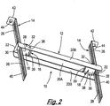
- FIGS 1 to 5 of the drawings show a suspension assembly 10, which comprises an elongate support member 12 and first and second substantially flat strips 14.
- the strips 14 are in the form of first and second elongate metallic straps disposed at opposite end regions 22 of the elongate support member 12.
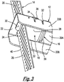
- the strips 14 are secured to the support member 12 by a securing arrangement 16 (see Figures 2 and 3 ).
- the securing arrangement 16 comprises first and second latch members 18 arranged at the opposite end regions 22 of the support member 12.
- the support member 12 comprises an elongate central portion 20A and a pair of opposed wall portions 20B extending from the central portion 20A.
- the central portion 20A defines first and second elongate openings 24 at the respective opposite end regions 22 of the support member 12. Each of the first and second strips 14 is received through a respective one of the first and second openings 24.
- Each of the first and second strips 14 defines a plurality of slots 26 along the length of the respective strip 14.
- Each of the first and second latch members 18 comprises a main portion 28 and an insertion portion 30.
- the insertion portions 30 can be inserted through a selected one of the slots 26 in each of the first and second strips 14, thereby securing the strips 14 to the support member 12.
- Each of the support members 12 comprises guide formations for guiding the latch members 18.
- the guide formations are in the form of respective first and second elongate holes 32 defined by the wall portions 20B at the first and second end regions 22 of the support member 12.
- Each of the latch members 18 comprises a pair of opposite cooperating portions 34 in the form of protrusions on the main portion 28.
- the cooperating portions 34 are received by the elongate holes 32 in the wall portions 20B.
- the elongate holes 32 are longer than the cooperating portions 34 to allow the latch members 18 to slide between securing and non-securing positions.
- the insertion portions 30 are not received in any of the slots 26 in the first and second strips 14, thereby allowing the strips 14 to be slid through the openings 24.
- the securing arrangement further includes urging means for urging the first and second latch members 18 to the securing positions.
- the securing arrangement comprises first and second urging members in the form of first and second tension springs 36.
- the first and second tension springs 36 are attached respectively to the first and second latch members 18 and to the support member 12 by means of hooks at opposite ends of the tension springs 36.
- the hooks are received in respective holes in the support member 12 and in the latch members 18, as would be understood by those skilled in the art.
- First and second detent members 38 are provided on respective wall portions 20B at opposite end regions 22 of the support member 12.
- the detent members 38 allow the latch members 18 to be mounted on the support member 12.
- detent member 38 Only one detent member 38 is provided at each of the end regions 22, but it will be appreciated that a respective detent member 38 could be provided in each wall portion 20B at each of the end regions 22.
- the first and second latch members 18 are pressed into place between the wall portions 20B until the cooperating portions 34 are received in the elongate holes 32.
- Each of the latch members 18 includes a tab 39 (see Figures 2 and 3 ) to allow the user to pull the latch member 18 to its non-securing position, thereby allowing the position of the support member 12 to be adjusted relative to the strips 14.
- Each of the strips 14 comprises an elongate portion 40, in which the slots 26 are defined.
- Each strip 14 has an attaching portion 42 for attaching the strips 14 to, for example, a roof or a ceiling.
- the attaching portion 42 defines a circular aperture 44 through which a fastener (not shown), such as a screw or a bolt, can be inserted to attach the strip 14 to the roof or ceiling.
- a fastener such as a screw or a bolt
- the strips 14 are attached to the roof or ceiling by means of the fastener.
- the latch members 18 are pulled to their non-securing positions by the user to allow the support member 12 to be mounted on the strips 14.
- the strips 14 are inserted through the openings 24 in the first and second end regions 22 of the support member 12.
- the support member 12 can be slid along the strips 14 to a desired position relative to the strips 14 while the latch members 18 are held in their non-securing positions.
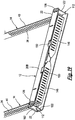
- the portions of the strips 14 extending below the support member 12 can then be deformed to a stowed condition by bending them upwardly, as shown by the arrow A in Figure 1 .
- the support member 12 could be of any suitable length. Also, the two tension springs 36 could be replaced by a single compression spring extending between the first and second latch members 18.
- the securing arrangement 16 may include locking formations for locking the latch members 18 in the securing positions; the slots 26 in the strips 14 may instead be holes that are not elongate; the slots 26 or the holes may be arranged in pairs; the attaching portion 42 may be provided with reinforcement; and the support member 12 may include formations such as slots or hooks to facilitate attachment of articles (e.g. pipes, cable tray).
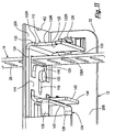
- FIGS 6 to 15 show a further embodiment of the suspension assembly, generally designated 110.
- the suspension assembly 110 comprises many of the features of the suspension assembly 10. These features have been designated with the same reference numerals as the corresponding features in Figures 1 to 5 .
- the suspension assembly 110 comprises a latch member 112 slidably attached to the support member 12.
- the latch member 112 is slidably movable between securing and non-securing positions.
- the latch member 112 has a main portion 114 and a securing portion 116 extending from the main portion 114.
- the securing portion 116 is receivable in a selected one of the slots 26 in the strip 14.
- the main portion 114 defines an elongate aperture 118.
- a mounting member 120 in the form of a rivet is received through the elongate aperture 118. There is, therefore, relative sliding movement between of the mounting member 120 and the main portion 114 when the latch member 112 slides between the securing and nosecuring positions.
- the mounting member 120 is in the form of a rivet, which can bear the working load of the suspension assembly 110 in the event that the support member 12 is used upside down.
- the latch member 112 further includes an end portion 122 connected to the main portion by a pair of connecting elements 124.
- the connecting elements 124 extend from the main portion 114, to the end portion 122 so that the securing portion 116 is arranged between the main portion 114 and the securing portion 116.
- the securing portion 116 is also arranged between the connecting elements 124.
- the suspension assembly 110 also includes a locking arrangement for locking the latch members 112 in their securing positions.
- the locking arrangement comprises two locking members 126 arranged on the support member 12 adjacent the respective opposite ends 22 thereof.
- the locking members 126 are attached to the support 12 at apertures 127, by means of insertion portions and detents, as explained below with reference to Figures 21 to 26 .
- Each locking member 126 comprises a button, and can be slid between a locked position shown in Figure 12 , and an unlocked position shown in Figure 13 .
- the end portion 122 of the latch member 112 defines two recesses 128A, 128B in the opposite side edges 130.
- One of the recesses, designated 128A, is defined in the side edge 130 adjacent the locking member 126.
- the end portion 122 includes cooperating formations in the form of inner and outer lugs 132A, 132B on the opposite edges 130.
- the recesses 128A, 128B are defined between the inner and outer lugs 132A, 132B.
- Arranging the locking member 126 in the unlocked position aligns the locking member 126 with the recess 128A. This allows the end portion 122 to move across the locking member 126 when the latch member 112 is moved between the non-securing and the securing positions.
- the end portion 122 extends across the locking member 126 in its unlocked position, so that the inner lug 132A is disposed above the locking member 126 and the outer lug 132B is disposed below the locking member 126, as shown in Figure 11 . This prevents the locking member 126 being moved to its locked position, thereby preventing the latch member 112 being locked in its non-securing position.
- the securing arrangement further includes resilient urging means 134.
- the urging means 134 comprises a leaf spring having a pair of opposite legs 136. The legs 136 are deformed into V shapes to provide the required resilience. The urging means 134 urges the latch member 112 towards the securing position.
- the urging means 134 is attached to the support member 12 by means of a pair of attaching elements 138 on the opposed wall portions 20B of the support member 12.
- the attaching elements 138 engage the legs 136 to attach them to the respective wall portion 20B.
- the urging means 134 further includes a cross member 140 extending between the legs 136.
- the latch member 112 includes a projecting portion 142 extending transverse to the main portion 114. In use, the projecting portion 142 extends downwardly from the main portion 114.
- the urging means 134 is attached to the member 112 at the projecting portion 142.
- the projecting portion 142 has a lower edge 144 providing a fulcrum about which the strip 14 can be bent when the strip 14 is deformed to the stowed condition.
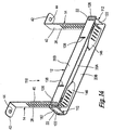
- Figures 14 and 15 show stowed regions 146 of the strips 14.
- Figure 15 shows one of the stowed regions146 deformed over the lower edge 144 of the projecting portion 142.
- FIG. 16 to 20 there is shown a further version of the suspension assembly 110 shown in Figures 6 to 15 .
- the suspension assembly 110 shown in Figures 16 to 20 comprises all the features of the suspension assembly shown in Figures 6 to 15 , and these features have been designated with the same reference numerals in Figures 16 to 20 as the corresponding features in Figures 6 to 15 .
- the suspension assembly 110 shown in Figures 16 to 20 further includes holding formations in the form of two holding tabs 150 in one of the wall portions 20B of the support member 12. Although the holding tabs 150 are shown provided only on one of the wall portions 20B. It will be appreciated that each of the wall portions 20B may include holding tabs 150. However, in the suspension assembly 110 shown in Figures 16 to 20 , the holding formations are provided only on one of the wall portions 20B.
- the wall portions 20B have first and second opposite edges, the first edge is attached to the main portion 20A.
- the second edge is a free edge.
- the holding formations are provided along the second edge.
- Each of the holding tabs 150 is formed as a cut out in the wall portion 20B, and has an end attached to the wall portion 20B.
- each of the holding tabs 150 Prior to use, each of the holding tabs 150 is in a non-holding position aligned with the wall portion 20B, as shown in Figures 16 and 17 .
- Each of the holding tabs 150 is deformably movable to a holding position by being bent along its end attached to the wall portion 20B towards the opposite wall portion 20B, as shown in Figures 18 , 19 and 20 .
- the holding tabs 150 are then deformed to their holding positions to extend underneath and across each of the stowed regions146 of the strips 14, thereby holding the stowed regions146 in their stowed positions between the wall portions 20B.
- the number of holding tabs 150 could be varied.
- the number of holding tabs 150 may depend upon the length of the support member 12. For example, in situations where the support member 12 is short, the support member may have only one holding tab 150 to hold both stowed regions 146.
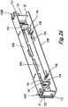
- FIGS 21 to 26 Further versions of the suspension assembly 110 are shown in Figures 21 to 26 .
- the locking members 126 are replaced by second locking members 126A on the support member 12.
- the locking members 126 are replaced by third locking members 126B on the support member 12.
- Each of the second and third locking members 126A, 126B is larger than the locking member 126 and is, thereby, more robust.
- Each of the second and third locking members 126A, 126B has a plurality of side members in the form of side walls 152.
- Each of the second and third locking members 126A, 126B may have four of the side walls 152.
- Each of the second and third locking members 126A, 126B also has a transverse portion 154 having ribs 155.
- the transverse portion 154 extends between the walls 152.
- the transverse portion 154 is substantially flat, to help prevent the locking member 126 deforming under an external load X, such as a packing/delivery load or caused by being dropped.
- Two opposite side walls 152 of the second and third locking members 126A, 126B each have a recessed middle portion 156.
- All the locking members 126, 126A, 126B have a pair of opposed insertion members 158 extending between the opposite recessed middle portions 156.
- a respective detent member 160 extends from each of the recessed portions 156.
- Each end 22 of the elongate central portion 20A of the support 12 defines a notch 162 which is directly aligned with the aperture 44 in the respective attaching portion 42.
- the elongate central portion provides a template to allow an installer to use the support 12 to mark the position on the ceiling for screws to attach the strips 14 thereto.
- the installer arranges the central portion 20A of the support 12 against the ceiling and marks the ceiling with a pen at each of the notches. This provides the centre marks for the drill hole so that the strips 14 are in the right position to be received through the openings 24 in the central portion 20A.
Landscapes
- Engineering & Computer Science (AREA)
- General Engineering & Computer Science (AREA)
- Mechanical Engineering (AREA)
- Architecture (AREA)
- Civil Engineering (AREA)
- Structural Engineering (AREA)
- Clamps And Clips (AREA)
- Supports For Pipes And Cables (AREA)
- Mutual Connection Of Rods And Tubes (AREA)
- Vehicle Body Suspensions (AREA)
- Fluid-Damping Devices (AREA)
- Operating, Guiding And Securing Of Roll- Type Closing Members (AREA)
- Details Of Indoor Wiring (AREA)
Claims (15)
- Aufhängungsanordnung (10), umfassend:ein Trägerelement (12) zum Tragen eines Gegenstands;einen länglichen, im Wesentlichen flachen Streifen (14); undeine Befestigungsanordnung (16);wobei das Trägerelement (12) eine Öffnung (24) definiert, durch die der Streifen (14) eingeführt werden kann, und der Streifen (14) eine Vielzahl von Durchlässen (26) definiert;die Befestigungsanordnung (16) ein Verriegelungselement (18) beinhaltet, das durch eine ausgewählte der Durchlässe (26) in dem Streifen (14) aufgenommen werden kann, um das Trägerelement (12) an dem Streifen (14) zu befestigen, wobei das Verriegelungselement (18) zwischen einer Befestigungs- und einer Nichtbefestigungsposition beweglich ist;wobei das Verriegelungselement (18) in der Befestigungsposition von einem der Durchlässe (26) in dem Streifen (14) aufgenommen wird, wodurch der Streifen (14) an dem Trägerelement (12) befestigt wird; unddadurch gekennzeichnet, dassdie Befestigungsanordnung (16) eine Vorspanneinrichtung (36) umfasst, um das Verriegelungselement (18) in die Befestigungsposition zu zwingen.
- Aufhängungsanordnung (10) nach Anspruch 1, umfassend einen ersten und einen zweiten der im Wesentlichen flachen Streifen (14) umfasst, wobei das Trägerelement (12) eine erste und eine zweite Öffnung (24) definiert, durch die jeweils ein entsprechender Streifen (14) eingeführt werden kann, wobei jeder von dem ersten und dem zweiten Streifen (14) eine Vielzahl von Durchlässe (26) definiert, und die Befestigungsanordnung (16) ein jeweiliges erstes und zweites Verriegelungselement (18) beinhaltet, die durch eine jeweilige ausgewählte der Durchlässe (26) in jedem Streifen (14) aufgenommen werden können, um das Trägerelement (12) an den Streifen (14) zu befestigen.
- Aufhängungsanordnung (10) nach Anspruch 2, wobei das Trägerelement (12) länglich ist und jede von der ersten und der zweiten Öffnungen (24) an gegenüberliegenden Endbereichen (22) des Trägerelements (12) definiert ist.
- Aufhängungsanordnung (10) nach Anspruch 2 oder 3, wobei jedes Verriegelungselement (18) zwischen einer Befestigungs- und einer Nichtbefestigungsposition beweglich ist, wobei in der Befestigungsposition der oder jeder Streifen (14) an dem Trägerelement (12) befestigt ist und jedes Verriegelungselement (18) von einem der Durchlässe (26) in dem jeweiligen Streifen (14) aufgenommen ist.
- Aufhängungsanordnung (10) nach einem vorherigen Anspruch, wobei die Vorspanneinrichtung (36) mindestens eine elastische Vorspanneinrichtung umfasst, um das oder jedes Verriegelungselement (18) in die Befestigungsposition zu zwingen, um von dem Durchlass (26) in dem oder jedem Streifen (14) aufgenommen zu werden.
- Aufhängungsanordnung (10) nach Anspruch 5, wobei die Vorspanneinrichtung ein Paar gegenüberliegender Schenkel (136) umfasst, wobei die Schenkel (136) geformt sind, um der Vorspanneinrichtung (36) Elastizität zu verleihen.
- Aufhängungsanordnung (10) nach Anspruch 6, wobei das Trägerelement (12) ein Paar gegenüberliegender Wandabschnitte (20B) umfasst, wobei jeder Wandabschnitt (20B) ein Befestigungselement zum Befestigen der Vorspanneinrichtung (36) an dem Trägerelement (12) beinhaltet, und wobei jedes Befestigungselement mit einem entsprechenden der Beine (136) zusammenwirkt, um die Vorspanneinrichtung (36) an dem Trägerelement (12) anzubringen.
- Aufhängungsanordnung (10) nach einem vorherigen Anspruch, wobei das oder jedes Verriegelungselement (18) einen Hauptabschnitt (28) und einen Einführungsabschnitt (30) an dem Hauptabschnitt (28) umfasst, wobei der Einführungsabschnitt (30) durch den ausgewählten Durchlass (26) in den jeweiligen ersten und zweiten Streifen (14) eingeführt wird, um die Streifen (14) an dem Trägerelement (12) zu befestigen, und das oder jedes Verriegelungselement (18) ferner umfassend einen Endabschnitt (122), der mit dem Hauptabschnitt (28) verbunden ist, wobei sich der Endabschnitt (122) quer zu dem Hauptabschnitt (28) erstreckt.
- Aufhängungsanordnung (10) nach Anspruch 8, wobei sich der Endabschnitt (122) über einen Endbereich (22) des Trägerelements (12) erstreckt, um zu ermöglichen, dass das Verriegelungselement (18) durch Drücken des Endabschnitts (122) in das Trägerelement (12) gedrückt wird.
- Aufhängungsanordnung (10) nach einem vorherigen Anspruch, wobei das oder jedes Verriegelungselement (18) einen länglichen Durchlass (26) definiert, um zu ermöglichen, dass das Verriegelungselement (18) verschiebbar an dem Trägerelement (12) montiert wird, und wobei die Aufhängungsanordnung (10) mindestens ein Montageelement an dem Trägerelement (12) umfasst, um das oder jedes Verriegelungselement (18) an dem Trägerelement (12) anzubringen.
- Aufhängungsanordnung (10) nach einem vorherigen Anspruch, umfassend eine Verriegelungsanordnung zum Verriegeln des oder jedes Verriegelungselements (18) in der Befestigungsposition, die Verriegelungsanordnung umfassend mindestens ein Verriegelungselement (126), wobei das oder jedes Verriegelungselement (126) zwischen einer verriegelten und entriegelten Position beweglich ist.
- Aufhängungsanordnung (10) nach Anspruch 11, wobei der Endabschnitt (122) eine innere und eine äußere Lasche (132A, 132B) aufweist und das Verriegelungselement (126) angeordnet ist, sodass das Verriegelungselement (126) zwischen den Laschen (132A, 132B) aufgenommen ist, wenn das Verriegelungselement (18) in der Nichtbefestigungsposition ist, sodass das Verriegelungselement (126) eine der Laschen (132A, 132B) eingreift, wenn das Verriegelungselement (126) in Richtung der verriegelten Position bewegt wird.
- Aufhängungsanordnung (10) nach einem vorherigen Anspruch, wobei der oder jeder Streifen (14) in einen verstauten Zustand verformbar ist, in dem sich ein verstaubarer Bereich des oder jedes Streifens (14) entlang des Trägerelements (12) erstreckt.
- Aufhängungsanordnung (10) nach Anspruch 13, wobei das Trägerelement (12) eine Halteformation beinhaltet, um den vorstehend erwähnten verstaubaren Bereich des Streifens (14) in dem verstauten Zustand zu halten, wobei die Halteformation von einer Nichthalteposition in eine Halteposition bewegbar ist, wodurch sich die Halteformation, wenn sie in der Halteposition ist, über den verstaubaren Bereich des Streifens (14) erstreckt, um den verstaubaren Bereich in dem vorstehend erwähnten verstauten Zustand zu halten.
- Aufhängungsanordnung (10) nach Anspruch 14, wobei das Trägerelement (12) einen mittleren Abschnitt und mindestens einen Wandabschnitt (20B) umfasst, der sich von dem zentralen Abschnitt erstreckt, wobei der Wandabschnitt (20B) einen ersten und einen zweiten gegenüberliegenden Rand aufweist und der Wandabschnitt (20B) entlang dem ersten Rand an dem mittleren Abschnitt angebracht ist, wobei der zweite Rand ein freier Rand ist, und wobei die Halteformation entlang dem freien Rand des Wandabschnitts (20B) bereitgestellt ist.
Priority Applications (1)
| Application Number | Priority Date | Filing Date | Title |
|---|---|---|---|
| PL17835488T PL3549215T3 (pl) | 2016-12-02 | 2017-11-24 | Zespół do podwieszania |
Applications Claiming Priority (5)
| Application Number | Priority Date | Filing Date | Title |
|---|---|---|---|
| GBGB1620545.2A GB201620545D0 (en) | 2016-12-02 | 2016-12-02 | Suspension assembly |
| GBGB1712770.5A GB201712770D0 (en) | 2017-08-09 | 2017-08-09 | Suspension assembly |
| GBGB1714160.7A GB201714160D0 (en) | 2017-09-04 | 2017-09-04 | Suspension assembly |
| GBGB1718940.8A GB201718940D0 (en) | 2017-11-16 | 2017-11-16 | Suspension assembly |
| PCT/GB2017/000171 WO2018100329A1 (en) | 2016-12-02 | 2017-11-24 | Suspension assembly |
Publications (2)
| Publication Number | Publication Date |
|---|---|
| EP3549215A1 EP3549215A1 (de) | 2019-10-09 |
| EP3549215B1 true EP3549215B1 (de) | 2021-09-29 |
Family
ID=60805530
Family Applications (1)
| Application Number | Title | Priority Date | Filing Date |
|---|---|---|---|
| EP17835488.2A Active EP3549215B1 (de) | 2016-12-02 | 2017-11-24 | Aufhängungseinheit |
Country Status (16)
| Country | Link |
|---|---|
| US (1) | US10914333B2 (de) |
| EP (1) | EP3549215B1 (de) |
| JP (1) | JP7005623B2 (de) |
| CN (1) | CN110036545B (de) |
| AU (1) | AU2017369798B2 (de) |
| CA (1) | CA3043555A1 (de) |
| CL (1) | CL2019001474A1 (de) |
| DK (1) | DK3549215T3 (de) |
| ES (1) | ES2896253T3 (de) |
| GB (1) | GB2558759B (de) |
| MX (1) | MX2019006180A (de) |
| PL (1) | PL3549215T3 (de) |
| PT (1) | PT3549215T (de) |
| RU (1) | RU2749603C2 (de) |
| WO (1) | WO2018100329A1 (de) |
| ZA (1) | ZA201903229B (de) |
Families Citing this family (14)
| Publication number | Priority date | Publication date | Assignee | Title |
|---|---|---|---|---|
| GB201812081D0 (en) | 2018-07-24 | 2018-09-05 | Gripple Ltd | Suspension assembly |
| GB2586780B (en) * | 2019-08-20 | 2023-01-04 | Terlok Ltd | Support structure |
| GB2598056B (en) * | 2019-09-09 | 2022-06-29 | Gripple Ltd | Suspension assembly |
| CN110671541A (zh) * | 2019-09-18 | 2020-01-10 | 马鞍山汉德绿色建筑环境科技有限公司 | 一种拼接式管道支架 |
| US11495952B2 (en) * | 2019-09-18 | 2022-11-08 | Erico International Corporation | Bracket system for mounting electrical boxes |
| US11349289B2 (en) | 2019-09-19 | 2022-05-31 | Erico International Corporation | Mounting bracket for electrical boxes |
| USD986721S1 (en) * | 2020-04-16 | 2023-05-23 | Gripple Limited | Suspension bracket assembly |
| GB202009393D0 (en) * | 2020-06-19 | 2020-08-05 | Gripple Ltd | Holding assembley |
| JP7499870B2 (ja) * | 2020-10-16 | 2024-06-14 | 三菱電機株式会社 | 環境状態管理装置及びエリア管理システム |
| GB2605237A (en) | 2020-11-30 | 2022-09-28 | Gripple Ltd | Bracing assembly and support system |
| GB2610473A (en) * | 2021-06-28 | 2023-03-08 | Gripple Ltd | Connecting Apparatus and Suspension Assembly |
| CN114811192B (zh) * | 2022-05-19 | 2023-09-22 | 杭州兴达电器工程有限公司 | 一种管线支架 |
| KR20230164337A (ko) * | 2022-05-25 | 2023-12-04 | 엘에스일렉트릭(주) | 온도 감시용 광섬유 케이블 타래 구조체 및 이를 포함하는 서버 랙 시스템 |
| US20240167276A1 (en) * | 2022-11-23 | 2024-05-23 | Hubbell Incorporated | Brace for ceiling drop |
Family Cites Families (25)
| Publication number | Priority date | Publication date | Assignee | Title |
|---|---|---|---|---|
| US3199815A (en) * | 1961-11-21 | 1965-08-10 | Martinkovic Paul Steve | Universal muffler hanger |
| CH400279A (de) * | 1963-04-19 | 1965-10-15 | Heer & Co | Aufhängeeinrichtung für Kabelkanäle aus gelochtem Blech |
| DE1280528B (de) * | 1966-10-29 | 1968-10-17 | Friedrich Frueh | Verstellbarer Abhaenger fuer die Tragschienen einer Unterdecke od. dgl. |
| US3565375A (en) * | 1969-04-03 | 1971-02-23 | Robert R Walker Jr | Plastic pipe hanger |
| US3938767A (en) * | 1974-10-30 | 1976-02-17 | Crouse-Hinds Company | Cable tray |
| US4004768A (en) * | 1975-08-13 | 1977-01-25 | Nickson Industries, Inc. | Universal joint hanger for tailpipes and the like |
| US4309019A (en) * | 1980-11-03 | 1982-01-05 | Bloom Stephen R | Adjustable tailpipe hanger |
| CH659509A5 (de) * | 1983-02-10 | 1987-01-30 | Heer & Co | Befestigungsmittel fuer die montage von tragvorrichtungen, insbesondere kabelkanaelen. |
| JPH0496244U (de) * | 1991-01-25 | 1992-08-20 | ||
| US5791607A (en) * | 1997-02-13 | 1998-08-11 | Thibault; Jean Pierre | Pipe support system |
| KR100260953B1 (ko) * | 1998-02-26 | 2000-07-01 | 김남식 | 건축물의 천정판 고정용 찬넬의 고정방법 |
| US6293056B1 (en) * | 1999-04-01 | 2001-09-25 | Ping He | Multi-purpose above-ceiling utility support system |
| AU2002232288A1 (en) * | 2001-02-09 | 2002-08-28 | Jum-Gyu Kim | Container for ship capable of height adjustment |
| US8033511B2 (en) * | 2008-07-29 | 2011-10-11 | Demetrios Grivas | Pipe support assembly |
| US20100133217A1 (en) * | 2008-12-03 | 2010-06-03 | Wen-Tsan Wang | Hanging closet organizer |
| FR2968472B1 (fr) * | 2010-12-06 | 2013-08-30 | Raymond A & Cie | Goulotte de reception d'elements allonges, son procede de montage et ensemble comprenant un support et une telle goulotte |
| CN202167797U (zh) * | 2011-08-10 | 2012-03-14 | 黄利兴 | 一种多媒体教学讲台用机架布线装置 |
| GB2494422A (en) * | 2011-09-07 | 2013-03-13 | Tyco Electronics Ltd Uk | Two component device for supporting and retaining wires and cables in a channel |
| IN2015DN02447A (de) * | 2012-09-04 | 2015-09-04 | Armstrong World Ind Inc | |
| CA2889176C (en) * | 2014-04-30 | 2022-08-16 | Cooper Technologies Company | Trapeze hanger system including trapeze hanger fitting |
| GB201412571D0 (en) * | 2014-07-15 | 2014-08-27 | Alphastrut Ltd And Munro Andrew And Amtec Solutions Ltd | Utility support apparatus |
| CN104377626B (zh) * | 2014-12-10 | 2017-02-22 | 重庆源隆科技有限公司 | 建筑用悬挂式桥架线缆槽总成及其线缆敷设方法 |
| KR101792233B1 (ko) * | 2015-05-18 | 2017-10-31 | 장재욱 | 행거 클램핑 장치 |
| CN205304090U (zh) * | 2015-12-22 | 2016-06-08 | 国网福建省电力有限公司泉州供电公司 | 一种三角联板卡具及双串耐张绝缘子更换装置 |
| CN105840003B (zh) * | 2016-04-28 | 2017-09-08 | 广东汇泰龙科技有限公司 | 一种插销机构的驱动控制系统及其控制方法 |
-
2017
- 2017-11-20 GB GB1719208.9A patent/GB2558759B/en active Active
- 2017-11-24 CN CN201780074389.6A patent/CN110036545B/zh active Active
- 2017-11-24 ES ES17835488T patent/ES2896253T3/es active Active
- 2017-11-24 PT PT178354882T patent/PT3549215T/pt unknown
- 2017-11-24 CA CA3043555A patent/CA3043555A1/en active Pending
- 2017-11-24 AU AU2017369798A patent/AU2017369798B2/en active Active
- 2017-11-24 MX MX2019006180A patent/MX2019006180A/es unknown
- 2017-11-24 PL PL17835488T patent/PL3549215T3/pl unknown
- 2017-11-24 EP EP17835488.2A patent/EP3549215B1/de active Active
- 2017-11-24 WO PCT/GB2017/000171 patent/WO2018100329A1/en unknown
- 2017-11-24 JP JP2019529486A patent/JP7005623B2/ja active Active
- 2017-11-24 DK DK17835488.2T patent/DK3549215T3/da active
- 2017-11-24 RU RU2019120232A patent/RU2749603C2/ru active
- 2017-11-24 US US16/463,077 patent/US10914333B2/en active Active
-
2019
- 2019-05-22 ZA ZA2019/03229A patent/ZA201903229B/en unknown
- 2019-05-30 CL CL2019001474A patent/CL2019001474A1/es unknown
Also Published As
| Publication number | Publication date |
|---|---|
| PT3549215T (pt) | 2021-11-03 |
| US20190376544A1 (en) | 2019-12-12 |
| GB2558759A (en) | 2018-07-18 |
| RU2749603C2 (ru) | 2021-06-16 |
| ZA201903229B (en) | 2021-01-27 |
| US10914333B2 (en) | 2021-02-09 |
| MX2019006180A (es) | 2019-08-21 |
| BR112019010763A2 (pt) | 2019-10-01 |
| EP3549215A1 (de) | 2019-10-09 |
| WO2018100329A1 (en) | 2018-06-07 |
| JP7005623B2 (ja) | 2022-01-21 |
| RU2019120232A (ru) | 2021-01-11 |
| CN110036545B (zh) | 2021-09-28 |
| RU2019120232A3 (de) | 2021-03-01 |
| AU2017369798B2 (en) | 2021-11-18 |
| CN110036545A (zh) | 2019-07-19 |
| CA3043555A1 (en) | 2018-06-07 |
| GB201719208D0 (en) | 2018-01-03 |
| JP2020514630A (ja) | 2020-05-21 |
| PL3549215T3 (pl) | 2022-01-10 |
| ES2896253T3 (es) | 2022-02-24 |
| DK3549215T3 (da) | 2021-10-25 |
| AU2017369798A1 (en) | 2019-05-30 |
| CL2019001474A1 (es) | 2019-10-18 |
| GB2558759B (en) | 2020-02-19 |
Similar Documents
| Publication | Publication Date | Title |
|---|---|---|
| EP3549215B1 (de) | Aufhängungseinheit | |
| EP4028669B1 (de) | Aufhängungseinheit | |
| AU2019311806B2 (en) | Suspension assembly | |
| US12049758B1 (en) | Apparatus and method for hanging architectural panels with concealed attachment points | |
| BR112019010763B1 (pt) | Conjunto de suspensão |
Legal Events
| Date | Code | Title | Description |
|---|---|---|---|
| STAA | Information on the status of an ep patent application or granted ep patent |
Free format text: STATUS: UNKNOWN |
|
| STAA | Information on the status of an ep patent application or granted ep patent |
Free format text: STATUS: THE INTERNATIONAL PUBLICATION HAS BEEN MADE |
|
| PUAI | Public reference made under article 153(3) epc to a published international application that has entered the european phase |
Free format text: ORIGINAL CODE: 0009012 |
|
| STAA | Information on the status of an ep patent application or granted ep patent |
Free format text: STATUS: REQUEST FOR EXAMINATION WAS MADE |
|
| 17P | Request for examination filed |
Effective date: 20190619 |
|
| AK | Designated contracting states |
Kind code of ref document: A1 Designated state(s): AL AT BE BG CH CY CZ DE DK EE ES FI FR GB GR HR HU IE IS IT LI LT LU LV MC MK MT NL NO PL PT RO RS SE SI SK SM TR |
|
| AX | Request for extension of the european patent |
Extension state: BA ME |
|
| DAV | Request for validation of the european patent (deleted) | ||
| DAX | Request for extension of the european patent (deleted) | ||
| GRAP | Despatch of communication of intention to grant a patent |
Free format text: ORIGINAL CODE: EPIDOSNIGR1 |
|
| STAA | Information on the status of an ep patent application or granted ep patent |
Free format text: STATUS: GRANT OF PATENT IS INTENDED |
|
| INTG | Intention to grant announced |
Effective date: 20210413 |
|
| GRAJ | Information related to disapproval of communication of intention to grant by the applicant or resumption of examination proceedings by the epo deleted |
Free format text: ORIGINAL CODE: EPIDOSDIGR1 |
|
| STAA | Information on the status of an ep patent application or granted ep patent |
Free format text: STATUS: REQUEST FOR EXAMINATION WAS MADE |
|
| GRAP | Despatch of communication of intention to grant a patent |
Free format text: ORIGINAL CODE: EPIDOSNIGR1 |
|
| STAA | Information on the status of an ep patent application or granted ep patent |
Free format text: STATUS: GRANT OF PATENT IS INTENDED |
|
| INTC | Intention to grant announced (deleted) | ||
| GRAS | Grant fee paid |
Free format text: ORIGINAL CODE: EPIDOSNIGR3 |
|
| INTG | Intention to grant announced |
Effective date: 20210727 |
|
| GRAA | (expected) grant |
Free format text: ORIGINAL CODE: 0009210 |
|
| STAA | Information on the status of an ep patent application or granted ep patent |
Free format text: STATUS: THE PATENT HAS BEEN GRANTED |
|
| RBV | Designated contracting states (corrected) |
Designated state(s): AL AT BE BG CH CY CZ DE DK EE ES FI FR GR HR HU IE IS IT LI LT LU LV MC MK MT NL NO PL PT RO RS SE SI SK SM TR |
|
| AK | Designated contracting states |
Kind code of ref document: B1 Designated state(s): AL AT BE BG CH CY CZ DE DK EE ES FI FR GR HR HU IE IS IT LI LT LU LV MC MK MT NL NO PL PT RO RS SE SI SK SM TR |
|
| REG | Reference to a national code |
Ref country code: CH Ref legal event code: EP Ref country code: AT Ref legal event code: REF Ref document number: 1435042 Country of ref document: AT Kind code of ref document: T Effective date: 20211015 |
|
| REG | Reference to a national code |
Ref country code: DE Ref legal event code: R096 Ref document number: 602017046911 Country of ref document: DE |
|
| REG | Reference to a national code |
Ref country code: DK Ref legal event code: T3 Effective date: 20211019 |
|
| REG | Reference to a national code |
Ref country code: IE Ref legal event code: FG4D |
|
| REG | Reference to a national code |
Ref country code: PT Ref legal event code: SC4A Ref document number: 3549215 Country of ref document: PT Date of ref document: 20211103 Kind code of ref document: T Free format text: AVAILABILITY OF NATIONAL TRANSLATION Effective date: 20211027 |
|
| REG | Reference to a national code |
Ref country code: SE Ref legal event code: TRGR |
|
| REG | Reference to a national code |
Ref country code: NL Ref legal event code: FP |
|
| REG | Reference to a national code |
Ref country code: LT Ref legal event code: MG9D |
|
| REG | Reference to a national code |
Ref country code: NO Ref legal event code: T2 Effective date: 20210929 |
|
| PG25 | Lapsed in a contracting state [announced via postgrant information from national office to epo] |
Ref country code: BG Free format text: LAPSE BECAUSE OF FAILURE TO SUBMIT A TRANSLATION OF THE DESCRIPTION OR TO PAY THE FEE WITHIN THE PRESCRIBED TIME-LIMIT Effective date: 20211229 Ref country code: LT Free format text: LAPSE BECAUSE OF FAILURE TO SUBMIT A TRANSLATION OF THE DESCRIPTION OR TO PAY THE FEE WITHIN THE PRESCRIBED TIME-LIMIT Effective date: 20210929 Ref country code: HR Free format text: LAPSE BECAUSE OF FAILURE TO SUBMIT A TRANSLATION OF THE DESCRIPTION OR TO PAY THE FEE WITHIN THE PRESCRIBED TIME-LIMIT Effective date: 20210929 Ref country code: FI Free format text: LAPSE BECAUSE OF FAILURE TO SUBMIT A TRANSLATION OF THE DESCRIPTION OR TO PAY THE FEE WITHIN THE PRESCRIBED TIME-LIMIT Effective date: 20210929 Ref country code: RS Free format text: LAPSE BECAUSE OF FAILURE TO SUBMIT A TRANSLATION OF THE DESCRIPTION OR TO PAY THE FEE WITHIN THE PRESCRIBED TIME-LIMIT Effective date: 20210929 |
|
| REG | Reference to a national code |
Ref country code: ES Ref legal event code: FG2A Ref document number: 2896253 Country of ref document: ES Kind code of ref document: T3 Effective date: 20220224 |
|
| PG25 | Lapsed in a contracting state [announced via postgrant information from national office to epo] |
Ref country code: LV Free format text: LAPSE BECAUSE OF FAILURE TO SUBMIT A TRANSLATION OF THE DESCRIPTION OR TO PAY THE FEE WITHIN THE PRESCRIBED TIME-LIMIT Effective date: 20210929 Ref country code: GR Free format text: LAPSE BECAUSE OF FAILURE TO SUBMIT A TRANSLATION OF THE DESCRIPTION OR TO PAY THE FEE WITHIN THE PRESCRIBED TIME-LIMIT Effective date: 20211230 |
|
| PG25 | Lapsed in a contracting state [announced via postgrant information from national office to epo] |
Ref country code: IS Free format text: LAPSE BECAUSE OF FAILURE TO SUBMIT A TRANSLATION OF THE DESCRIPTION OR TO PAY THE FEE WITHIN THE PRESCRIBED TIME-LIMIT Effective date: 20220129 Ref country code: SK Free format text: LAPSE BECAUSE OF FAILURE TO SUBMIT A TRANSLATION OF THE DESCRIPTION OR TO PAY THE FEE WITHIN THE PRESCRIBED TIME-LIMIT Effective date: 20210929 Ref country code: RO Free format text: LAPSE BECAUSE OF FAILURE TO SUBMIT A TRANSLATION OF THE DESCRIPTION OR TO PAY THE FEE WITHIN THE PRESCRIBED TIME-LIMIT Effective date: 20210929 Ref country code: EE Free format text: LAPSE BECAUSE OF FAILURE TO SUBMIT A TRANSLATION OF THE DESCRIPTION OR TO PAY THE FEE WITHIN THE PRESCRIBED TIME-LIMIT Effective date: 20210929 Ref country code: AL Free format text: LAPSE BECAUSE OF FAILURE TO SUBMIT A TRANSLATION OF THE DESCRIPTION OR TO PAY THE FEE WITHIN THE PRESCRIBED TIME-LIMIT Effective date: 20210929 |
|
| PG25 | Lapsed in a contracting state [announced via postgrant information from national office to epo] |
Ref country code: MC Free format text: LAPSE BECAUSE OF FAILURE TO SUBMIT A TRANSLATION OF THE DESCRIPTION OR TO PAY THE FEE WITHIN THE PRESCRIBED TIME-LIMIT Effective date: 20210929 |
|
| REG | Reference to a national code |
Ref country code: DE Ref legal event code: R097 Ref document number: 602017046911 Country of ref document: DE |
|
| PG25 | Lapsed in a contracting state [announced via postgrant information from national office to epo] |
Ref country code: LU Free format text: LAPSE BECAUSE OF NON-PAYMENT OF DUE FEES Effective date: 20211124 |
|
| PLBE | No opposition filed within time limit |
Free format text: ORIGINAL CODE: 0009261 |
|
| STAA | Information on the status of an ep patent application or granted ep patent |
Free format text: STATUS: NO OPPOSITION FILED WITHIN TIME LIMIT |
|
| 26N | No opposition filed |
Effective date: 20220630 |
|
| PG25 | Lapsed in a contracting state [announced via postgrant information from national office to epo] |
Ref country code: SI Free format text: LAPSE BECAUSE OF FAILURE TO SUBMIT A TRANSLATION OF THE DESCRIPTION OR TO PAY THE FEE WITHIN THE PRESCRIBED TIME-LIMIT Effective date: 20210929 |
|
| REG | Reference to a national code |
Ref country code: AT Ref legal event code: UEP Ref document number: 1435042 Country of ref document: AT Kind code of ref document: T Effective date: 20210929 |
|
| P01 | Opt-out of the competence of the unified patent court (upc) registered |
Effective date: 20230523 |
|
| PG25 | Lapsed in a contracting state [announced via postgrant information from national office to epo] |
Ref country code: CY Free format text: LAPSE BECAUSE OF FAILURE TO SUBMIT A TRANSLATION OF THE DESCRIPTION OR TO PAY THE FEE WITHIN THE PRESCRIBED TIME-LIMIT Effective date: 20210929 |
|
| PG25 | Lapsed in a contracting state [announced via postgrant information from national office to epo] |
Ref country code: SM Free format text: LAPSE BECAUSE OF FAILURE TO SUBMIT A TRANSLATION OF THE DESCRIPTION OR TO PAY THE FEE WITHIN THE PRESCRIBED TIME-LIMIT Effective date: 20210929 Ref country code: HU Free format text: LAPSE BECAUSE OF FAILURE TO SUBMIT A TRANSLATION OF THE DESCRIPTION OR TO PAY THE FEE WITHIN THE PRESCRIBED TIME-LIMIT; INVALID AB INITIO Effective date: 20171124 |
|
| PGFP | Annual fee paid to national office [announced via postgrant information from national office to epo] |
Ref country code: NL Payment date: 20231122 Year of fee payment: 7 |
|
| PGFP | Annual fee paid to national office [announced via postgrant information from national office to epo] |
Ref country code: ES Payment date: 20231215 Year of fee payment: 7 |
|
| PGFP | Annual fee paid to national office [announced via postgrant information from national office to epo] |
Ref country code: TR Payment date: 20231115 Year of fee payment: 7 Ref country code: SE Payment date: 20231123 Year of fee payment: 7 Ref country code: PT Payment date: 20231110 Year of fee payment: 7 Ref country code: NO Payment date: 20231121 Year of fee payment: 7 Ref country code: IT Payment date: 20231130 Year of fee payment: 7 Ref country code: IE Payment date: 20231117 Year of fee payment: 7 Ref country code: FR Payment date: 20231124 Year of fee payment: 7 Ref country code: DK Payment date: 20231122 Year of fee payment: 7 Ref country code: DE Payment date: 20231120 Year of fee payment: 7 Ref country code: CZ Payment date: 20231110 Year of fee payment: 7 Ref country code: CH Payment date: 20231202 Year of fee payment: 7 Ref country code: AT Payment date: 20231117 Year of fee payment: 7 |
|
| PGFP | Annual fee paid to national office [announced via postgrant information from national office to epo] |
Ref country code: PL Payment date: 20231109 Year of fee payment: 7 Ref country code: BE Payment date: 20231121 Year of fee payment: 7 |
|
| PG25 | Lapsed in a contracting state [announced via postgrant information from national office to epo] |
Ref country code: MK Free format text: LAPSE BECAUSE OF FAILURE TO SUBMIT A TRANSLATION OF THE DESCRIPTION OR TO PAY THE FEE WITHIN THE PRESCRIBED TIME-LIMIT Effective date: 20210929 |