EP3548823B1 - Boîte collectrice d'un fluide réfrigérant comprenant au moins un dispositif de positionnement angulaire d'un conduit - Google Patents
Boîte collectrice d'un fluide réfrigérant comprenant au moins un dispositif de positionnement angulaire d'un conduit Download PDFInfo
- Publication number
- EP3548823B1 EP3548823B1 EP17816948.8A EP17816948A EP3548823B1 EP 3548823 B1 EP3548823 B1 EP 3548823B1 EP 17816948 A EP17816948 A EP 17816948A EP 3548823 B1 EP3548823 B1 EP 3548823B1
- Authority
- EP
- European Patent Office
- Prior art keywords
- duct
- pipe
- angular positioning
- positioning device
- collecting box
- Prior art date
- Legal status (The legal status is an assumption and is not a legal conclusion. Google has not performed a legal analysis and makes no representation as to the accuracy of the status listed.)
- Active
Links
Images





Classifications
-
- F—MECHANICAL ENGINEERING; LIGHTING; HEATING; WEAPONS; BLASTING
- F28—HEAT EXCHANGE IN GENERAL
- F28F—DETAILS OF HEAT-EXCHANGE AND HEAT-TRANSFER APPARATUS, OF GENERAL APPLICATION
- F28F27/00—Control arrangements or safety devices specially adapted for heat-exchange or heat-transfer apparatus
- F28F27/02—Control arrangements or safety devices specially adapted for heat-exchange or heat-transfer apparatus for controlling the distribution of heat-exchange media between different channels
-
- F—MECHANICAL ENGINEERING; LIGHTING; HEATING; WEAPONS; BLASTING
- F28—HEAT EXCHANGE IN GENERAL
- F28F—DETAILS OF HEAT-EXCHANGE AND HEAT-TRANSFER APPARATUS, OF GENERAL APPLICATION
- F28F9/00—Casings; Header boxes; Auxiliary supports for elements; Auxiliary members within casings
- F28F9/02—Header boxes; End plates
- F28F9/026—Header boxes; End plates with static flow control means, e.g. with means for uniformly distributing heat exchange media into conduits
- F28F9/027—Header boxes; End plates with static flow control means, e.g. with means for uniformly distributing heat exchange media into conduits in the form of distribution pipes
- F28F9/0273—Header boxes; End plates with static flow control means, e.g. with means for uniformly distributing heat exchange media into conduits in the form of distribution pipes with multiple holes
-
- F—MECHANICAL ENGINEERING; LIGHTING; HEATING; WEAPONS; BLASTING
- F25—REFRIGERATION OR COOLING; COMBINED HEATING AND REFRIGERATION SYSTEMS; HEAT PUMP SYSTEMS; MANUFACTURE OR STORAGE OF ICE; LIQUEFACTION SOLIDIFICATION OF GASES
- F25B—REFRIGERATION MACHINES, PLANTS OR SYSTEMS; COMBINED HEATING AND REFRIGERATION SYSTEMS; HEAT PUMP SYSTEMS
- F25B39/00—Evaporators; Condensers
- F25B39/02—Evaporators
- F25B39/028—Evaporators having distributing means
Definitions
- the field of the present invention is that of heat exchangers equipping air conditioning installations for a vehicle, in particular a motor vehicle.
- the invention relates more specifically to the methods of distributing a refrigerant fluid inside a manifold box that such a heat exchanger comprises.
- a vehicle is currently equipped with an air conditioning installation for thermally treating the air present or sent into the passenger compartment of the vehicle.
- an air conditioning installation for thermally treating the air present or sent into the passenger compartment of the vehicle.
- Such an installation comprises a closed circuit inside which circulates a refrigerant fluid.
- the circuit essentially comprises a compressor, a condenser, an expansion valve and at least one heat exchanger.
- the heat exchanger commonly comprises a bundle of tubes interposed between a header box and a coolant return box.
- the refrigerant fluid is admitted through an inlet mouth inside a collector box, circulates in successive paths in the tubes of the bundle between the collector box and a return box, then is evacuated outside the exchanger thermal through an outlet.
- the heat exchanger is for example an evaporator providing heat exchange between the refrigerant fluid and an air flow passing therethrough.
- the refrigerant fluid circulates inside the tubes of the bundle and the air flow circulates along the tubes of the bundle for its cooling.
- a problem posed lies in the fact that the refrigerant fluid is in the liquid / gaseous two-phase state when it is admitted inside the heat exchanger. Due to the difference between the physical properties between liquid and gas, the refrigerant tends to separate between its liquid phase and its gas phase.
- This phenomenon generates a heterogeneity in the temperature of the air flow which has passed through the heat exchanger in operation. This heterogeneity complicates the thermal management of the device which receives the heat exchanger and ultimately involves temperature differences between two zones of the passenger compartment, while the same air flow temperature is required.
- the present invention relates to a collecting box for a refrigerant fluid for a heat exchanger, in particular organized to supply refrigerant fluid to the tubes of a bundle of tubes that the heat exchanger comprises.
- a collector box according to the preamble of claim 1 is known from WO 2005/121685 .
- the subject of the invention is also a heat exchanger equipped with a manifold according to the invention.
- the heat exchanger is in particular designed to equip an air conditioning installation of a vehicle, in particular an automobile.
- An object of the invention is to improve the uniformity of the temperature of the heat exchanger in operation and finally to improve its efficiency. It is more specifically targeted by the invention to improve the distribution of the refrigerant fluid in the collector box, in particular by means of a spraying of the refrigerant liquid housed inside the manifold.
- the aim is in particular to provide a manifold capable of supplying the tubes of the bundle with refrigerant fluid by providing, on the one hand, efficient homogenization of the refrigerating fluid between its liquid phase and its gas phase, and, on the other hand, a homogeneous distribution of the fluid. refrigerant inside each of the tubes of the heat exchanger bundle.
- Another object of the invention is to provide a manifold that can be obtained industrially at lower costs, while being able to provide the desired performance of the heat exchanger.
- the aim is in particular to equip the collector box with a device for distributing the refrigerant fluid to the tubes of the bundle that the heat exchanger comprises, which can be obtained at lower costs while providing optimized performance of the heat exchanger. It is also aimed in particular to organize the distribution device so as to provide its reliable mounting inside the manifold box at lower costs.
- the diversity of structures of heat exchangers is to be assessed in particular with regard to the number of tubes in the bundle that they comprise, the modes of circulation of the refrigerant fluid inside the heat exchanger and / or the relative positions between the mouth of the heat exchanger. 'inlet and outlet of the refrigerant fluid that comprises the heat exchanger.
- the collector box of the invention is formed from a wall and accommodates at least one duct extended along a longitudinal axis.
- One of the longitudinal ends of the duct communicates with an inlet mouth for the admission of the refrigerant fluid inside the duct.
- the duct has at least one orifice oriented in a direction transverse to its longitudinal axis.
- Communication between the conduit and the inlet is a fluid communication between them.
- Such fluid communication provides a circulation of the refrigerant fluid between the inlet mouth and the duct and more specifically between the inlet mouth and the recess of the duct.
- the notion of communication between organs is considered as a fluid communication allowing the passage of a fluid from one of the organs to the other, in particular the refrigerant fluid.
- the placing in communication between organs is a configuration of the organs relative to each other providing a circulation of a fluid between the organs, the fluid being able to circulate from an organ to another organ with which it is in communication.
- the duct comprises or is in communication with the inlet mouth at a first of its longitudinal ends and is closed at a second longitudinal end.
- the orifices are in particular distributed along the duct along at least part of its length.
- the refrigerant fluid is more specifically provided to be admitted inside the duct at its first end comprising the inlet mouth. Closing the duct at its second end forces the refrigerant fluid to pass through the orifice or orifices for its evacuation out of the duct.
- the manifold box is provided with at least one angular positioning device having at least the duct around its longitudinal axis in a predetermined angular position with respect to the wall of the manifold box.
- the angular positioning device in particular forms a means for orienting at least one orifice that the duct comprises in a predefined transverse orientation around the longitudinal axis of the duct.
- the wall of the manifold box is configured to delimit a chamber housing the duct and onto which tubes of the heat exchanger bundle to be supplied with refrigerant fluid from the manifold box are provided to open out.
- the wall of the manifold can be considered as a fixed mark with regard to the aptitude of the duct to be arranged in a predetermined angular position around its longitudinal axis inside the chamber.
- the wall of the manifold box is capable of being made up of various wall elements which are integral with one another and which can be placed inside or outside the chamber. Such wall elements are likely to be arranged in various ways and / or to extend in various directions defined by an orthonormal reference.
- One or more orifices are thus angularly orientable around the longitudinal axis of the duct via at least one angular positioning device fitted to the manifold.
- the angular position of the duct is in particular determined via said at least one angular positioning device according to the path to be traveled by the refrigerant fluid evacuated from the duct prior to its distribution to the tubes of the bundle opening onto the chamber.
- the refrigerant fluid is evacuated out of the duct through one or more orifices in at least one transverse direction defined by the angular positioning device.
- the refrigerant fluid evacuated from the duct is not only homogeneous between a liquid phase and a gas phase, but also can be distributed in an efficient and homogeneous manner towards each of the tubes of the bundle.
- control by means of the angular positioning device of the angular orientation of the duct provides a circulation of the refrigerant fluid inside the collector box according to a path which can be adapted to provide a homogeneous delivery of the refrigerant fluid to the tubes of the bundle. .
- the performance of the heat exchanger is increased.
- the temperature of the air passing through the heat exchanger is found to be considerably balanced along all the tubes of the bundle.
- the temperature of a cooling liquid circulating through a hydraulic cooling circuit extending at least in part along the heat exchanger is also considerably balanced during its passage along the assembly. tubes in the bundle.
- the angular positioning device is a first angular positioning device assigned to the transverse positioning of the duct inside the manifold box.
- the concept of positioning transverse of the duct is assessed with respect to its longitudinal axis.
- the first angular positioning device notably forms a member for blocking the duct in a predetermined angular position.
- the duct is blocked in particular directly or indirectly on the wall of the manifold via at least the first angular positioning device.
- the first angular positioning device comprises a stop for axial positioning of the duct in the manifold box along its longitudinal axis.
- the first angular positioning device has a single angular positioning position of the duct.
- the first angular positioning device determines a single angular positioning position of the duct.
- the unique angular position of the duct can be predefined according to the arrangement of a given manifold box and / or according to the organization of a given heat exchanger, to optimize the path traveled by the refrigerant fluid inside the box. collector.
- the mixing of the refrigerant between its liquid phase and its gas phase can be optimized and the distribution of the refrigerant. refrigerant to be obtained performing equally towards each of the tubes of the bundle.
- the first angular positioning device has multiple selective positions for angular positioning of the duct.
- the first angular positioning device determines several angular positions of the duct which are selectable as a function of the configuration of the manifold and / or of the number of tubes of the bundle to be supplied with coolant.
- the selection of a given angular position of the duct is in particular carried out by an operator during the installation of the conduit inside the manifold box and / or during the installation inside the collector box of a device for distributing the refrigerant fluid comprising at least the conduit. More particularly, an operator can select a given angular position of said at least one duct in accordance with a predefined assembly instruction.
- the number of predetermined angular positions of the duct is between 1 and 24, while providing angular ranges for selective indexing of the duct around its longitudinal axis of between 15 ° and 360 °.
- the first angular positioning device is interposed between the duct and the wall of the manifold.
- the first angular positioning device is interposed in particular between at least one of the longitudinal ends of the duct and the wall of the manifold.
- a seal is interposed between the duct and the wall of the manifold.
- the seal is preferably arranged between the first angular positioning device and the part of the duct which comprises the orifice or orifices and which is intended to be housed inside the chamber.
- Said at least one angular positioning device comprises in particular a pair of cooperating members via at least one set of complementary shapes.
- the cooperating members are in particular configured as interlocking members via the complementary shapes that they comprise.
- a first member of the first angular positioning device is provided at any one of the longitudinal ends of the duct and cooperates with a second member preferably provided on the wall of the manifold box.
- the first member of the first control device angular positioning can be arranged directly at the axial end of the wall forming the duct.
- the first member of the first angular positioning device is capable of being provided on a tip fitted to one of its longitudinal ends.
- the members of the first angular positioning device are advantageously placed in cooperation with one another.
- An axial abutment of the duct against the wall of the header box provides axial positioning of the duct inside the header box.
- the axial positioning stop of the duct is capable of being formed by a separate stop which comprises a first angular positioning device.
- the axial positioning stop of the duct is also capable of comprising the cooperating members of the first angular positioning device, which bears axially against one another when they are placed in cooperation at the end of the axial stroke of the duct.
- the duct houses a mixer for the refrigerant fluid between its liquid phase and its gas phase.
- the mixer extends inside at least partly along the duct, in particular in its part comprising the orifice or orifices.
- Such a mixer is a generator member of a disturbance of a laminar flow of the refrigerant fluid flowing through it.
- the mixer is in particular formed of a body forming obstacles against a laminar flow of the refrigerant fluid inside the duct. The homogenization of the refrigerant between its liquid phase and its gas phase during its circulation inside the duct is thus obtained efficient prior to its evacuation through the orifice or orifices.
- the mixer is in particular configured as at least one permeable body allowing circulation of the refrigerant fluid therethrough along its lengthwise extension and its transverse extension.
- the mixer is likely to expand to the interior of the duct by being formed of a single body, or by being formed of several bodies distributed along the duct.
- the mixer is in particular made from a metallic material, such as aluminum-based, allowing it to be soldered inside the duct.
- the mixer can be made of synthetic material and introduced into the collector box after its manufacture.
- the refrigerant is in a first step homogenized between its liquid phase and its gas phase inside the duct by means of the mixer, then in a second step the refrigerant is made even more homogeneous by its spraying during its evacuation out of the pipe. led through the orifice (s).
- the homogenization of the refrigerant fluid between its liquid phase and its gas phase in successive stages reinforces the homogeneous supply of the tubes of the bundle with refrigerant fluid, the mixture of which between its liquid phase and its gas phase is optimized.
- a second angular positioning device places the mixer in a predetermined angular position with respect to the orifice, or even, where appropriate, with respect to several orifices that the duct comprises.
- the second angular positioning device angularly arranges the mixer with respect to the duct around its longitudinal axis, with regard to the angular position of the orifice (s) that it comprises.
- the second angular positioning device has a single angular positioning position of the mixer inside the duct.
- the second angular positioning device potentially determines a single angular positioning position of the mixer with respect to the duct around its longitudinal axis.
- the second angular positioning device has multiple selective positions for angular positioning of the duct.
- the second angular positioning device makes it possible to selectively vary the relative angular positions between the mixer and the conducted around its longitudinal axis.
- a first member of the second angular positioning device is provided on the mixer and cooperates with a second member provided on the duct.
- the members of the second angular positioning device cooperate in particular with each other via at least one set of complementary shapes.
- a first member of the second angular positioning device is provided at one of the longitudinal ends of the mixer and is housed inside a cavity of the duct comprising the second member.
- Said cavity is in particular a blind cavity formed inside the first duct at its second end longitudinally opposite to the first end of the duct communicating with the inlet mouth.
- the second angular positioning device preferably comprises an axial positioning stop for the mixer inside the duct.
- the members of the second angular positioning device are advantageously placed in cooperation along the longitudinal axis of the duct.
- An axial abutment of the mixer against the duct provides axial positioning of the mixer inside the duct.
- the stop for axial positioning of the mixer inside the duct is formed by the bottom of the blind cavity comprising the second member of the second angular positioning device.
- the second angular positioning device positions in particular at least one opening of the mixer opposite at least one orifice of the duct.
- the second angular positioning device forms in particular an angular and / or axial positioning member of the mixer inside the duct with respect to its longitudinal axis, and a member for locking the mixer in a predetermined position inside the duct.
- the comparison of the openings that the mixer has on the outlet of at least one orifice provides circulation of the refrigerant fluid from the interior of the mixer to the orifice (s).
- the opening (s) are for example formed of at least one slot formed along the mixer and opening out to one or more orifices distributed along the duct.
- the opening (s) are for example also formed from at least one outlet of a thread of a propeller formed at the periphery of the mixer.
- the opening (s) are for example also formed from the outlet towards the outside of the mixer of at least one portion of the propeller that the mixer comprises.
- At least one closure member is positioned at at least one of the longitudinal ends of the duct.
- a given closure member closes at least a second longitudinal end of the duct.
- the closing of the second longitudinal end of the duct can also be achieved by the wall of the manifold box, which in other words then forms the closure member.
- the second longitudinal end of the duct is located longitudinally opposite the first longitudinal end of the duct.
- the collector box comprises the duct, then called the first duct, and a second duct which surrounds the first duct.
- the second duct comprises at least one passage for the evacuation outside the second duct of the refrigerant fluid evacuated by the first duct through the orifice or orifices.
- the second duct may have one or more passages distributed along its length.
- the second duct notably surrounds the first duct along at least part of its length, and more specifically the part of the first duct comprising the orifice (s).
- an assembly comprising the second duct and the first duct optionally accommodating the mixer advantageously forms a device for distributing the refrigerant fluid capable of being installed inside the manifold box.
- the assembly comprising the first duct optionally housing the mixer forms a refrigerant fluid distribution device suitable for being installed inside the manifold provided with the second duct, which is then for example brazed on or formed by the wall of the manifold.
- the second duct is in particular closed at its longitudinal ends to force the circulation of the refrigerant fluid coming from the first duct through the passage or passages.
- the closing of at least one of the longitudinal ends of the second duct may advantageously be carried out via one or more said closing members fitted to at least one of the longitudinal ends of the first duct.
- the closure of at least one of the longitudinal ends of the second duct can also be achieved by the wall of the manifold box, which then forms at least one said closure member.
- the closure of at least one of the longitudinal ends of the second duct and / or of the second end of the first duct by the wall of the manifold can be carried out either directly or by means of a support of the first. conduit and / or the second conduit incorporated into the wall of the manifold, in particular by brazing.
- the closing of at least one of the longitudinal ends of the second duct can also be achieved by at least one closure member fitted to at least one of the longitudinal ends of the second duct.
- at least one closure member fitted to at least one of the longitudinal ends of the second duct can also form a closure member of the second. longitudinal end of the first duct.
- the first duct and the second duct are likely to be eccentric with respect to one another or to be coaxial.
- the first duct and the second duct in particular each have an annular conformation preferably centered on the longitudinal axis of the first duct.
- the cross sections of the first duct and of the second duct can be of similar or differentiated geometrical conformations as to each other, without prejudging their relative positions eccentric or coaxial, for example being individually circular in conformation. , oblong or ovoid.
- the first duct and the second duct are coaxial.
- the coaxial position of the first duct and of the second duct makes it possible to simplify the organization of the first angular positioning device and preferably also of a third angular positioning device of the second duct relative to the first duct around its longitudinal axis as described. further away.
- the coaxial position of the first duct and of the second duct also facilitates the cost-effective arrangement of the manifold while providing a high-performance homogeneous mixture of the refrigerant between its liquid phase and its gaseous phase and a homogeneous distribution of the refrigerant fluid.
- set of tubes in the bundle to be supplied with coolant.
- the first angular positioning device is interposed between the first duct and the second duct.
- the second duct is preferably in particular positioned in a predetermined angular position on the manifold, in particular via a third angular positioning device.
- the angular positioning of the first duct relative to the wall of the manifold box is carried out via the first angular positioning device, one of the members of which is integral with the second conduit itself integral with the wall of the manifold in a predetermined angular position.
- a first member of the first angular positioning device is provided on one of the longitudinal ends of the first duct and cooperates with a second member of the first angular positioning device provided on one of the longitudinal ends of the second lead.
- the first angular positioning device is interposed between the first duct and the wall of the manifold.
- the header box is preferably equipped with a third angular positioning device for angularly orienting the second duct around the longitudinal axis of the first duct in at least one predetermined angular position relative to the wall of the header box and / or by relative to the orifice or orifices that the first duct has.
- a third angular positioning device has the second duct around the longitudinal axis of the first duct in at least one predetermined angular position with respect to the orifice or with respect to several orifices that the first duct comprises. .
- the third angular positioning device is for example interposed between the first duct and the second duct.
- the third angular positioning device is interposed between the second duct and the wall of the manifold.
- the second duct is preferably placed around the first duct at a transverse distance with respect to the longitudinal axis of the first duct, leaving between them a channel for circulating the refrigerant fluid.
- the passage or passages are angularly offset around the longitudinal axis of the duct in order to optimize the path traveled by the refrigerant fluid between the first duct and the second duct through the channel formed between them.
- the one or more passages and the orifice or orifices are angularly offset with respect to each other at an angle less than or equal to 180 ° around the longitudinal axis of the first duct.
- the relative angular positions between the passage (s) and the orifice (s) can be controlled by means of the first angular positioning device and / or the third angular positioning device, in order to provide a predetermined path for the circulation of the refrigerant fluid inside the channel at least partly around the first duct.
- the third angular positioning device is in particular a transverse positioning member of the second duct inside the manifold with respect to the longitudinal axis of the first duct.
- the third angular positioning device in particular also forms a member for blocking the second duct in at least one predetermined angular and / or axial position on the wall of the manifold and / or on the first duct.
- the blocking of the second duct is preferably carried out via the third angular positioning device, to avoid complicating the arrangement of the first duct.
- the third angular positioning device is interposed between the second duct and the wall of the manifold to avoid complicating the arrangement of the first duct.
- the first angular positioning device is preferably interposed between the first duct and the wall of the manifold.
- a first member of the third angular positioning device is formed on one of the longitudinal ends of the second duct and cooperates with a second member formed on the wall of the manifold box.
- the first angular positioning device is interposed between one of the ends of the first duct and the wall of the header box and the third angular positioning device is interposed between the wall of the header box and the end of the second duct disposed longitudinally opposite the end of the first duct provided with the first member of the first angular positioning device.
- the architecture of a distribution device formed by the assembly comprising the first duct and the second duct is advantageously simplified thereby.
- the first angular positioning device and the third angular positioning device can be interposed in staged succession between the first duct, the second duct and the wall of the manifold.
- the first angular positioning device is interposed between the first duct and the second duct and the third angular positioning device is interposed between the second duct and the wall of the manifold.
- the first angular positioning device is interposed between the first duct and the wall of the manifold and the third angular positioning device is interposed between the second duct and the first duct.
- the third angular positioning device has multiple selective positions allowing, alone or in combination with the first angular positioning device, to vary around the longitudinal axis of the first duct an angular offset between the second duct. and the first duct or in other words an angular offset between the orifice (s) and the passage (s).
- the third angular positioning device determines a single angular positioning position of the second duct.
- the angular position of the second duct is in particular determined via the third angular positioning device according to the path to be traveled by the refrigerant fluid discharged from the second duct, prior to the supply of refrigerant fluid to the tubes of the bundle opening onto the manifold box.
- the third angular positioning device comprises a stopper ensuring axial positioning of the second duct in the wall of the manifold box.
- At least two orifices are aligned along the first duct along a first straight line. At least two passages are aligned along the second duct along a second straight line. The first straight line and the second straight line are in particular parallel to the longitudinal axis of the first duct.
- the first angular positioning device and / or the third angular positioning device make it possible in particular to control an angular offset between the first straight line and the second straight line around the longitudinal axis of the first duct.
- orifice distributions along the first duct and passages along the second duct can be applied.
- the passages and / or the orifices can be distributed while being aligned along several straight lines parallel to the longitudinal axis of the first duct.
- the passages and / or the orifices can be distributed in staggered rows.
- the passages and / or the orifices can be distributed along at least one portion of the helix.
- the configuration, the number and / or the distribution of the orifices along the first duct can be advantageously determined independently of the configuration, the number and / or the distribution of the passages along the second duct.
- the orifices are advantageously configured to optimize the mixture obtained between the liquid phase and the gas phase of the refrigerant fluid discharged from the first duct through the orifices.
- the passages are advantageously configured to make and improve the homogenization of the distribution of the refrigerant fluid along the second duct towards each of the tubes of the bundle to be supplied which the heat exchanger comprises.
- At least one closure member is positioned at one of the longitudinal ends of the second duct and / or at the second longitudinal end of the first duct, being configured to close the second duct and / or the second end. longitudinal of the first duct.
- At least one of the angular positioning devices is in particular made of a metallic material, such as based on aluminum for example, and advantageously provides the assembly by brazing, in particular by brazing together the cooperating members of the angular positioning devices, between the first duct and the wall of the header box and / or between the first duct and the mixer and / or between the first duct and the second duct and / or between the second duct and the wall of the header box.
- a distribution device comprising the first duct and the second duct each provided with a first member participating in an angular positioning device assigned to them can be obtained at moderate costs, while being competitive with regard to the performance obtained from the 'heat exchanger. More particularly, the assembly of the conduits together and / or of the mixer inside the first conduit can be advantageously carried out during a brazing operation in the furnace via the members of the angular positioning devices which are assigned to them. The costs of obtaining the collector box are thus moderate.
- a subject of the invention is also a heat exchanger comprising at least one manifold according to the invention.
- tubes of a bundle of tubes open out into a chamber formed by the wall of the manifold.
- the tubes are successively arranged in a longitudinal direction of extension of the manifold.
- the chamber accommodates at least the first duct and / or also the second duct.
- At least one angular positioning device positions at least the first duct in a predetermined angular position around its longitudinal axis relative to the position of the outlets of the tubes of the bundle on the chamber.
- the tubes of the bundle are capable of being placed in interposition between the collector box and a return box for the refrigerant fluid to the collector box.
- the tubes of the bundle extend in particular in a direction perpendicular to the longitudinal direction of the manifold.
- the orifice opens into the chamber opposite the outlets of the tubes of the bundle on the chamber with respect to the longitudinal axis of the first duct.
- the second duct is in contact with the wall of the manifold box delimiting the chamber. At least one passage of the second duct is opposite the outlet of at least one tube of the bundle on the chamber.
- the heat exchanger is configured to be used in particular as an evaporator.
- the heat exchanger can for example be used to cool an air flow passing through it.
- the heat exchanger can be used to cool a liquid dedicated to the cooling of an organ, such as at least one battery of a vehicle supplying the energy necessary at least in part for its propulsion.
- the subject of the invention is also a refrigerant fluid circuit comprising at least one compressor, a condenser, an expansion device and a heat exchanger in accordance with the invention, through which a refrigerant fluid flows.
- the subject of the invention is also a ventilation, heating and / or air conditioning installation, or air conditioning installation, configured to equip a vehicle, in particular a motor vehicle.
- the air conditioning installation of the invention comprises at least one heat exchanger according to the invention.
- the angular positioning of the first duct inside the collector box and / or relative to the second conduit and / or relative to the outlets of the tubes of the bundle through the wall of the collector box delimiting the chamber makes it possible to adjust the '' orientation of the orifices and / or passages according to the performance obtained from the supply of coolant to the tubes of the bundle of a heat exchanger of given structure.
- the first angular positioning device and / or the third angular positioning device make it possible to adjust an angular offset between the orifices and passages, to determine an optimum path for the circulation of the refrigerant fluid between the first duct and the second duct and / or inside the manifold chamber.
- the first angular positioning device and / or the third angular positioning device make it possible to optimize the circulation of the refrigerant fluid inside the manifold box prior to its distribution to the tubes of the bundle.
- the first duct can optionally be equipped or not with the mixer, depending on the structure of the heat exchanger.
- a mixer housed in the first duct can be of diverse structures.
- the angular and / or axial position of the mixer inside the first duct can be adapted with respect to the orifices.
- Such advantages do not preclude a configuration with a single angular positioning position of at least one of the angular positioning devices, allowing mass production of a manifold configured to equip a heat exchanger of given structure.
- the manifold can easily be configured at low cost according to the requirements regarding the performance of the heat exchanger according to its organization and / or its nominal power.
- an air conditioning installation for a vehicle comprises a closed circuit 1 inside which circulates a refrigerant fluid FR.
- the circuit 1 essentially comprises, successively along the direction S1 of circulation of the refrigerant fluid FR, a compressor 2, a condenser 3 or gas cooler, an expansion member 4 and at least one heat exchanger 5 .
- circuit 1 The example given of a minimum architecture of circuit 1 is given as an indication and is not restrictive as regards the scope of the invention with regard to various potential architectures of circuit 1.
- the heat exchanger 5 is for example dedicated to cooling an air flow FA passing through it, as illustrated on the figure 2 .
- Such an air flow FA is used in particular to heat treat the air in the passenger compartment of the vehicle or for example also to cool a component of the vehicle in operation.
- the heat exchanger 5 is dedicated to the cooling of a liquid used to cool a component of the vehicle in operation, such as one or more batteries supplying electrical energy to a propulsive electric motorization of the vehicle.
- the heat exchanger 5 comprises a bundle 6 interposed between a collector box 7 and a return box 8.
- the collector box 7 extends in a longitudinal direction D1 oriented perpendicularly to a direction D3 of extension of the tubes 12 of the bundle 6 between the manifold 7 and the return box 8.
- the manifold 7 defines a chamber 9 supplied with refrigerant fluid FR through an inlet 10.
- the refrigerant fluid FR circulates inside the heat exchanger 5 to cool at least the tubes 12 of the bundle 6, then is discharged out of the heat exchanger 5 through an outlet 11.
- the outlet 11 is provided through the manifold 7, which implies that the heat exchanger 5 is a circulating heat exchanger in "U”.
- the outlet opening 11 can be formed through the return box 8, which then implies that the heat exchanger 5 is a heat exchanger with circulation in “I”.
- the heat exchanger 5 is of the U-shaped circulation type of the refrigerant fluid FR.
- the heat exchanger 5 is intended for cooling an air flow FA.
- the tubes 12 of the bundle 6 typically comprise fins 13 promoting heat exchange between the air flow FA and the tubes 12 of the bundle 6.
- the air flow FA passes through the bundle 6 transversely to the general plane P1 of the exchanger. thermal 5, flowing along the tubes 12.
- the refrigerant fluid FR circulates from the collector box 7 to a first layer 12a of tubes 12 of the bundle 6 dedicated to supplying the return box 8 with refrigerant fluid FR. Then the refrigerant FR circulates from the return box 8 to the collecting box 7 through a second layer 12b of tubes 12 of the bundle 6. The first layer 12a and the second layer 12b are superimposed in the direction of flow of the flow of air FA through the heat exchanger 5.
- Such a configuration of the heat exchanger 5 makes it particularly useful to obtain a homogeneous distribution of the refrigerant fluid FR between its phase. liquid and its gas phase and a homogeneous distribution of the refrigerant fluid FR along the manifold 7 towards each of the tubes 12 of the first layer 12a of the bundle 6.
- the chamber 9 houses a distribution device 18 extending along a longitudinal direction D2 parallel to the longitudinal direction D1 of extension of the manifold 7.
- the distribution device 18 comprises a duct 14 extending along a longitudinal axis A1 between a first end 15 and a second end 16 of the conduit 14.
- the conduit 14 is intended in particular to provide a homogenization of the refrigerant fluid FR between its liquid phase and its gas phase when it is discharged from the conduit 14.
- the longitudinal axis A1 of the duct 14 is oriented parallel to the direction D1 of extension of the manifold 7 and defines the longitudinal direction D2 of extension of the distribution device 18.
- the distribution device 18 is potentially centered inside of the collector box 7 as shown on the figure 1 or to be eccentric inside the manifold 7 with respect to a median longitudinal axis A2 of extension of the manifold 7 as illustrated in the figure figure 2 .
- a first longitudinal end 15 of the duct 14 comprises the inlet mouth 10 for the supply of refrigerant fluid FR from the distribution device 18 via the duct 14.
- the inlet mouth 10 is capable of receiving the refrigerant fluid FR from the. outside of the distribution device 18 or directly via a junction member of the heat exchanger 5 with the fluid circuit 1 illustrated in figure 1 .
- the second end 16 of the duct 14 is closed.
- At least one orifice 17 is made through the duct 14 for the evacuation of the refrigerant fluid FR from the duct 14 to the chamber 9.
- the duct preferably comprises a plurality of orifices 17 formed over at least part of its length to promote the homogenization of the refrigerant fluid discharged along the duct 14 between its liquid phase and its gas phase.
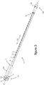
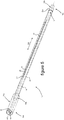
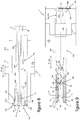
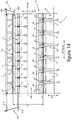
- the distribution devices 18 illustrated on the figures 3 to 6 are at least in part arranged to be housed in manifold boxes 7 illustrated in the figures 12 to 14 .
- the tubes 12 of the first layer 12a of tubes 12 of the bundle 6 which the heat exchanger 5 comprises are supplied with refrigerant fluid FR from the manifolds 7.
- the distribution devices 18 illustrated in each of these figures comprise at least a first duct 14 provided with a plurality of orifices 17 through which the refrigerant fluid FR admitted inside the first duct 14 is discharged, as illustrated. on the figures 12 to 14 .
- the inlet mouth 10 is for example formed of an opening passing longitudinally through a first end piece 23a fitted to the first longitudinal end 15 of the first duct 14.
- the first end piece 23a is housed in a first support 25a intended to be brazed on the wall 7a of the manifold 7, as for example illustrated in FIG. figure 8 .
- the first support 25a is provided at a first longitudinal end 15a of the dispensing device 18.
- the first end piece 23a is housed inside a blind housing 36d formed in the first support 25a and crossed by the first duct 14, such as 'apparent on the figure 8 .
- a first angular positioning device 30a is interposed between the first duct 14 and the first support 25a.
- the first angular positioning device 30a has multiple positions to make it possible to orient the first duct 14 angularly about its longitudinal axis A1 according to various predefined angular positions.
- the orifices 17 can be angularly arranged via the first angular positioning device 30a according to an angular position selected by an operator when mounting the distribution device 18 inside the manifold.
- the first angular positioning device 30a comprises a first member 31a formed on the first end piece 23a and cooperating with a second member 31b formed on the first support 25a.
- the members 31a, 31b of the first angular positioning device 30a comprise a set of complementary shapes arranged in the example illustrated in grooves 34b cooperating with a notch 34a, each of the grooves 34b receiving a notch of the notch 34a which is assigned to it.
- the notching 34a forms the first member 31a of the first angular positioning device 30a and is provided on the first end piece 23a.
- the grooves 34b form a second member 31b of the first angular positioning device 30a and are formed on the first support 25a.
- the notching 34a and the grooves 34b extend in the longitudinal direction D2 of the distribution device 18, being angularly distributed around the longitudinal axis A1 of the first duct 14.
- the bringing into cooperation between the members 31a, 31b of the first device angular positioning 30a is thus produced longitudinally along the longitudinal axis A1 of the first duct 14.
- the axial abutment of the first duct 14 against the first support 25a provides an axial positioning of the distribution device 18 inside the manifold 7.
- the axial abutment of the first duct 14 against the first support 25a is for example produced via a stop 32 arranged as a collar and fitted to the first duct 14 at its first longitudinal end 15.
- the axial abutment of the first duct 14 against the first support 25a can also be carried out, for example, via the members 31a, 31b of the first angular positioning device 30a.
- the second longitudinal end 16 of the first duct 14 is closed by a second end piece 23b equipping the first duct 14.
- the second end piece 23b is housed inside a second support 25b intended to be brazed on the wall 7a of the manifold box.
- the second support 25b comprises a blind recess 36b receiving the second end piece 23b. More particularly, the second support 25b is in particular arranged in a blind tube 26b formed at a second longitudinal end 16a of the dispensing device 18. The blind tube 26b comprises the blind recess 36b for receiving the second end piece 23b.
- the first duct 14 houses a mixer 19 extending along a longitudinal axis A3 coaxial with the longitudinal axis A1 of the first duct 14.
- the mixer 19 is in particular formed of at least one permeable body through which the refrigerant fluid is suitable. to circulate.
- the mixer 19 is a member capable of mixing the refrigerant fluid flowing through it between its liquid phase and its gas phase.
- the permeable body forming the mixer 19 is capable of comprising specific openings 37 provided to open out into the orifices 17 of the first duct 14, as illustrated for example on the figures 9 and 13 .
- the figure 7 illustrates an exemplary embodiment of a mixer 19 capable of equipping a distribution device 18 of the invention.
- the mixer 19 is formed by a body 19a comprising propeller portions 19b successively disposed along the mixer 19 while being wound around the longitudinal axis A3 of the mixer 19.
- the propeller portions 19b are successively angularly offset with respect to each other around the longitudinal axis A3 of the mixer 19.
- the propeller portions 19b provide guide rails for the refrigerant flowing along the mixer 19 opening towards the 'exterior of the mixer 19 transversely to its longitudinal axis A3, leaving the openings 37 provided to be placed opposite the orifices 17 of the first duct 14.
- mixer 19 can be formed from a body comprising perforated reliefs providing obstacles against a laminar flow of refrigerant fluid therethrough.
- the mixer 19 may include one or more openings 37 arranged in a slot or in a window opening onto several orifices 17.
- the opening 37 is capable of extending over the major part of the mixer 19 by opening onto all of the orifices 17.
- the mixer mixer 19 can also be free from openings 37 specifically provided to open out towards the orifices 17 of the first duct 14.
- a second angular positioning device 30c is interposed between the first duct 14 and the mixer.
- the second angular positioning device 30c makes it possible in particular to orient the openings 37 of the mixer 19 in the direction of the orifices 17, as illustrated in the figures. figures 9 and 13 .
- the second angular positioning device 30c comprises a first member 38a formed at the end of the mixer 19 and cooperating with a second member 38b formed on the second end piece 23b.
- the second angular positioning device 30c is capable of having multiple angular positioning positions of the mixer 19 inside the first duct 14.
- the members 38a and 38b of the second angular positioning device 30c can have a parallelepipedal conformation forming multiple facets 39a angularly distributed around the longitudinal axis of the first duct 14.
- the mixer 19 can be disposed selectively at the interior of the first duct 14 in various angular positions.
- the first member 38a of the second angular positioning device 30c is arranged as a finger 39 housed in a second cavity 36c forming the second member 38b of the second angular positioning device 30c.
- the finger 39 and the second cavity 36c are centered on the longitudinal axis A3 of the mixer 19 and each have at least one facet 39a providing a rotational locking of the mixer 19 on itself.
- the second angular positioning device 30c has a single angular positioning position.
- the first member of the second angular positioning device 30c is formed by a male member arranged longitudinally as an extension of the mixer 19.
- the first member is housed in a said second cavity 36c of complementary shape forming the second member 38b.
- the members of the second angular positioning device 30c extend parallel to the longitudinal axis A3 of the mixer 19.
- the configurations of the members of the second angular positioning device 30c are generally of a configuration of centered revolution. on the longitudinal axis of the mixer and on the longitudinal axis of the first duct.
- the first member is arranged as a key 40a formed at the periphery of the longitudinal end of the mixer oriented towards the second end piece.
- the first member is formed by a relief 40b or 40c formed by machining or by crushing the longitudinal end of the mixer oriented towards the second end piece 23b.
- the relief 40b is for example of parallelepipedal conformation as illustrated in diagram (d).
- the relief 40c is for example still of ovoid conformation as illustrated in diagram (e).
- the first member is formed of a flat 40d formed along an extension of the longitudinal end of the mixer oriented towards the second end piece 23b.
- the second support 25b is in particular formed by an extension of a second duct 21 surrounding the first conduit 14.
- the first duct 14 is surrounded by the second duct 21 which comprises a plurality of passages 20 opening out towards the outside of the distribution device 18.
- the first duct 14 and the second duct 21 are preferably mounted coaxially via the first support 25a and the second support 25b, as for example illustrated in the figures 8 and 9 .
- the first support 25a forms a closure member 25c of the first longitudinal end 15b of the second duct 21.
- the second support 25b forms a closure member 25d of the second ends 16, 16b of the first duct 14 and of the second duct 21, via the blind recess 36b formed inside the second support 25b.
- the refrigerant fluid FR evacuated from the first duct 14 through the orifices 17 is capable of being evacuated outside the distribution device 18 through the passages 20 for supplying the refrigerant fluid to the tubes 12 of the bundle 6 which the exchanger comprises thermal 5.
- the orifices 17 are aligned along a first straight line L1 and the passages 20 are aligned along a second straight line L2.
- the first straight line L1 and the second straight line L2 are parallel to the longitudinal axis A1 of the first duct 14.
- the first straight line L1 and the second straight line L2 are arranged diametrically opposite to each other with respect to the longitudinal axis A1 of the first duct 14, in a direction DT transverse to the distribution device 18.
- the second duct 21 surrounds the first duct 14 at a transverse distance, leaving between them a channel 22 for circulating the refrigerant fluid discharged from the first duct 14 towards the passages 20 of the second duct 21.
- the refrigerant fluid FR discharged through the orifices 17 is able to circulate inside the channel 22 around the first duct 14 to the passages 20 for its evacuation out of the distribution device 18.
- a third angular positioning device 30b is interposed between the second support 25b and the wall 7a of the manifold 7.
- the third angular positioning device 30b makes it possible to orient the passages 20 according to at least one predetermined angular position around the longitudinal axis A1 of the first duct 14.
- the third angular positioning device 30b has a single angular positioning position.
- the orifices 17 can be positioned via the first angular positioning device 30a according to the angular position of the passages 20 defined by the third angular positioning device 30b.
- the third angular positioning device 30b is capable of having multiple angular positioning positions, for example by being arranged in a manner analogous to the configuration of the first angular positioning device 30a illustrated in FIG. figure 8 .
- the passages 20 and the orifices 17 can be angularly positioned with respect to each other at predefined angular positions. as shown on the figure 14 .
- the orifices 17 and / or the passages 20 can in particular be angularly positioned relative to the outlets 24 of the tubes 12 of the bundle 6 of the heat exchanger 5 oriented towards the chamber 9 delimited by the wall 7a of the manifold 7.
- the third angular positioning device 30b comprises a first member 33a formed on the second support 25b and cooperating with a second member 33b formed on the wall 7a of the manifold 7.
- the first member 33a of the third angular positioning device 30b is for example formed by a groove 35a formed at the end of the second support 25b.
- the groove 35a accommodates a plate 35b forming the second member 33b of the third angular positioning device 30b.
- the plate 35b is in particular attached to the wall 7a of the manifold 7 at its face oriented towards the outside of the chamber 9.
- the first member 33a of the third angular positioning device 30b is formed by a plate 35c attached to the end of the second support 25b.
- the plate 35c comprises a flat 35d carried against the wall 7a of the manifold 7.
- the third angular positioning device 30b can be arranged according to the various examples illustrated in the diagrams (c), (d), (e), and (f) of the figure 11 .
- the first longitudinal end 15b of the second duct 21 is housed in a first cavity 36a which the first support 25a comprises.
- the first support 25a thus forms a centering member between the second duct 21 and the first duct 14, the first end 15 of the first duct 14 being centered on the first support 25a via the first end piece 23a.
- the second end 16 of the first duct 14 is housed via the second end piece 23b in the blind recess 36b in the second support 25b.
- the second support 25b thus forms a relative centering member between the first duct 14 and the second duct 21.
- the coaxial positioning between the first duct 14 and the second duct 21 is obtained of quality by means of both of their longitudinal ends 15, 15b and 16, 16b.
- the bringing into cooperation between the members 33a, 33b of the third angular positioning device 30b is carried out longitudinally.
- An axial abutment between the members 33a, 33b of the third angular positioning device 30b provides a relative axial positioning between the first duct 14 and the second duct 21 and / or an axial positioning of the second duct 21 inside the box. collector 7.
- the axial positioning obtained between the first duct 14 and the second duct 21 makes it possible to arrange the orifices 17 and the passages 20 axially with respect to one another.
- the axial positioning of the distribution device 18 thus obtained inside the manifold 7 makes it possible to arrange at least the orifices 17 and / or the passages 20 axially with respect to each other and / or with respect to the outlets of the tubes of the beam on chamber 9.
- manifolds 7 of a heat exchanger 5 each include a distribution device 18.
- the distribution devices 18 are housed inside the chamber 9 formed inside the manifold 7, extending along a longitudinal direction D2 parallel to the longitudinal direction D1 of the manifold 7.
- the chamber 9 is delimited by the wall 7a of the manifold 7 extending along the longitudinal axis A1 of the duct 14 and through which the tubes 12 open. of the bundle 6 in the heat exchanger 5.
- the area of the wall 7a of the manifold 7 delimiting the chamber 9 is formed by eyelets 7b formed as an extension of plates delimiting the tubes 12 of the bundle 6.
- the eyelets 7b are successively butted in the longitudinal direction D1 of the manifold 7 and are traversed by the distribution device in its longitudinal direction D2.
- the distribution devices 18 are centered inside the chamber 9 of the manifold 7 on the median longitudinal axis A2 of extension of the manifold 7. According to a variant, the distribution devices 18 may be eccentric with respect to the median longitudinal axis A2 of the manifold 7.
- the angular positioning devices 30a, 30b, 30c are shown diagrammatically interposed between the members of the manifold 7 on which the members 31a, 31b are formed; 33a, 33b, 38a, 38b of the angular positioning devices 30a, 30b, 30c shown for example on the figures 3 to 6 and 8 to 11 .
- the manifold 7 is provided with a distribution device 18 illustrated in the figures 3 and 4 .
- the manifold 7 is provided with a distribution device 18 illustrated in the figures 3 and 4 and equipped with a mixer 19 as described and shown in the figures 6, 7 and 9 .
- the manifold 7 is provided with a distribution device 18 illustrated in the figures 3 and 4 surrounded by a second duct 21 as described and shown in the figures 5 and 6 and the figures 8 and 9 .
- the distribution device 18 is mounted on the collector box 7 by leaving a space E1 for circulating the refrigerant fluid FR between the first duct 14 and the wall 7a of the collector box 7 delimiting the chamber 9.
- the distribution device 18 partially occupies the volume of the chamber 9 in the transverse direction DT to the longitudinal axis A1 of the first duct 14.
- the orifices 17 open onto the chamber 9 by being oriented via the first angular positioning device 30a in an angular position determined with respect to the outlets 24 of the tubes 12 of the bundle 6 on the chamber 9.
- the orifices 17 open out into the chamber 9 opposite the outlets 24 of the tubes 12 of the bundle 6 on the chamber 9 in a direction transverse DT with respect to the longitudinal axis A1 of the first duct 14.
- the circulation path of the refrigerant fluid FR inside the chamber 9 prior to its distribution to the tubes 12 of the bundle 6 is thus optimized.
- the refrigerant fluid FR admitted into the first duct 14 is discharged through the orifices 17, then circulates inside the space El around the first duct 14 to the outlets 24 of the tubes 12 of the bundle 6 inside the the collector box 7.
- the mixer 19 is housed inside and along the first duct 14.
- the mixer 19 comprises the openings 37 which are arranged opposite the orifices 17 to promote the evacuation of the refrigerant fluid FR out of the mixer 19 towards the orifices 17
- the openings 37 and the orifices 17 are in direct communication with one another.
- the outlets 24 of the openings 37 oriented towards the outside of the mixer 19 are in direct communication with the outlets 24 of the orifices 17 towards the inside of the first duct 14.
- the arrangement facing the openings 37 and the orifices 17 is controlled via the second angular positioning device 30c.
- the refrigerant fluid FR admitted into the first duct 14 circulates through the mixer 19 and then is discharged out of the mixer 19 through the openings 37 to the orifices 17, through which the refrigerant fluid FR is discharged out of the first duct 14.
- the distribution device 18 occupies the entire volume of the chamber 9 in the transverse direction DT to the longitudinal axis A1 of the first duct 14.
- the distribution device 18 is in particular fixed by brazing via the second duct 21 on the wall 7a of the manifold 7.
- the second duct 21 surrounds the first duct 14 at a transverse distance DT, leaving between them the channel 22 for circulating the refrigerant fluid FR inside the distribution device 18.
- the orifices 17 are oriented via the first angular positioning device 30a and / or the third angular positioning device 30b to the opposite of the passages 20 relative to the longitudinal axis A1 of the first duct 14.
- the passages 20 open individually into the outlets 24 of the tubes 12 of the bundle 6.
- the configuration of the passages 20 matches at least the configuration of the outlets 24 of the tubes 12 of the bundle 6 through the wall 7a of the manifold 7 delimiting the chamber 9.
- the distribution of the refrigerant fluid FR to each of the tubes 12 of beam 6 is obtained reliably and efficiently.
- the refrigerant fluid FR is evacuated out of the distribution device 18 through the passages 20 directly towards each of the tubes 12 of the bundle 6, in a homogeneous manner for all the tubes 12 of the bundle 6.
- the refrigerant fluid FR admitted into the first duct 14 is evacuated through the orifices 17 towards the channel 22, circulates inside the channel 22 around the first duct 14 then is evacuated out of the second duct 21 through the passages 20 towards the tubes 12 of bundle 6.
Landscapes
- Engineering & Computer Science (AREA)
- Physics & Mathematics (AREA)
- Thermal Sciences (AREA)
- Mechanical Engineering (AREA)
- General Engineering & Computer Science (AREA)
- Heat-Exchange Devices With Radiators And Conduit Assemblies (AREA)
Description
- Le domaine de la présente invention est celui des échangeurs thermiques équipant les installations de conditionnement d'air pour un véhicule, notamment automobile. L'invention relève plus spécifiquement des modalités de distribution d'un fluide réfrigérant à l'intérieur d'une boîte collectrice que comporte un tel échangeur thermique.
- Un véhicule est couramment équipé d'une installation de conditionnement d'air pour traiter thermiquement l'air présent ou envoyé dans l'habitacle du véhicule. Une telle installation comprend un circuit fermé à l'intérieur duquel circule un fluide réfrigérant. Successivement suivant le sens de circulation du fluide réfrigérant à son travers, le circuit comprend essentiellement un compresseur, un condenseur, un détendeur et au moins un échangeur thermique.
- L'échangeur thermique comporte couramment un faisceau de tubes interposés entre une boîte collectrice et une boîte de renvoi du fluide réfrigérant. Le fluide réfrigérant est admis à travers une bouche d'entrée à l'intérieur d'une boîte collectrice, circule suivant des chemins successifs dans les tubes du faisceau entre la boîte collectrice et une boîte de renvoi, puis est évacué hors de l'échangeur thermique à travers une bouche de sortie.
- L'échangeur thermique est par exemple un évaporateur procurant un échange thermique entre le fluide réfrigérant et un flux d'air le traversant. Dans ce cas, le fluide réfrigérant circule à l'intérieur des tubes du faisceau et le flux d'air circule le long des tubes du faisceau pour son refroidissement.
- Un problème posé réside dans le fait que le fluide réfrigérant est à l'état diphasique liquide/gazeux lorsqu'il est admis à l'intérieur de l'échangeur thermique. Du fait de la différence entre les propriétés physiques entre le liquide et le gaz, le fluide réfrigérant tend à se séparer entre sa phase liquide et sa phase gazeuse.
- Il en résulte une hétérogénéité de l'alimentation des tubes du faisceau au regard des différentes phases du fluide réfrigérant, selon leur position par rapport à la bouche d'entrée du fluide réfrigérant à l'intérieur de la boîte collectrice. Plus particulièrement, les tubes du faisceau situés au plus proche de la bouche d'entrée sont principalement alimentés en liquide et inversement les tubes du faisceau les plus éloignés de la bouche d'entrée sont principalement alimentés en gaz.
- Ce phénomène génère une hétérogénéité de la température du flux d'air qui a traversé l'échangeur thermique en fonctionnement. Cette hétérogénéité complique la gestion thermique de l'appareil qui reçoit l'échangeur thermique et in fine implique des écarts de températures entre deux zones de l'habitacle, alors que la même température de flux d'air est demandée.
- Il est connu de loger un conduit pourvu d'une pluralité d'orifices à l'intérieur d'une boîte collectrice. Le fluide réfrigérant en phase liquide est ainsi projeté à travers les orifices sous forme de gouttelettes sur la totalité de la longueur du conduit, tel qu'il ressort du document
EP 2 392 886 (DELPHI TECH INC). - Une telle organisation n'est cependant pas optimale du point de vue de l'homogénéisation de la température du flux d'air en sortie de l'échangeur thermique.
- La présente invention a pour objet une boîte collectrice d'un fluide réfrigérant pour un échangeur thermique, notamment organisée pour alimenter en fluide réfrigérant des tubes d'un faisceau de tubes que comporte l'échangeur thermique. Une telle boîte collectrice selon le préambule de la revendication 1 est connue de
WO 2005/121685 . - L'invention a aussi pour objet un échangeur thermique équipé d'une boîte collectrice conforme à l'invention. L'échangeur thermique est notamment agencé pour équiper une installation de conditionnement d'air d'un véhicule, notamment automobile.
- Un but de l'invention est de parfaire l'homogénéité de la température de l'échangeur thermique en fonctionnement et finalement d'améliorer son rendement. Il est plus spécifiquement visé par l'invention de parfaire la distribution du fluide réfrigérant dans la boîte collectrice, notamment au moyen d'un conduit de pulvérisation du liquide réfrigérant logé à l'intérieur de la boîte collectrice.
- Il est plus spécifiquement visé par l'invention de procurer une alimentation des tubes du faisceau à partir d'un fluide réfrigérant homogène entre sa phase liquide et sa phase gazeuse.
- Il est encore plus spécifiquement visé par l'invention de procurer une alimentation homogène en fluide réfrigérant de l'ensemble des tubes du faisceau débouchant sur la boîte collectrice.
- Il est notamment visé de proposer une boîte collectrice apte à alimenter en fluide réfrigérant les tubes du faisceau en procurant d'une part une homogénéisation performante du fluide réfrigérant entre sa phase liquide et sa phase gazeuse, et d'autre part une distribution homogène du fluide réfrigérant à l'intérieur de chacun des tubes du faisceau de l'échangeur thermique.
- Un autre but de l'invention est de proposer une boîte collectrice pouvant être obtenue industriellement à moindres coûts, tout en étant apte à procurer la performance recherchée de l'échangeur thermique.
- Il est notamment visé d'équiper la boîte collectrice d'un dispositif de distribution du fluide réfrigérant vers les tubes du faisceau que comporte l'échangeur thermique, qui puisse être obtenu à moindres coûts tout en procurant une performance optimisée de l'échangeur thermique. Il est encore notamment visé d'organiser le dispositif de distribution pour procurer à moindres coûts son montage fiable à l'intérieur de la boîte collectrice.
- La diversité de structures des échangeurs thermiques est notamment à apprécier au regard du nombre de tubes du faisceau qu'ils comportent, des modalités de circulation du fluide réfrigérant à l'intérieur de l'échangeur thermique et/ou des positions relatives entre la bouche d'entrée et la bouche de sortie du fluide réfrigérant que comporte l'échangeur thermique.
- La boîte collectrice de l'invention est formée d'une paroi et loge au moins un conduit étendu suivant un axe longitudinal. L'une des extrémités longitudinales du conduit communique avec une bouche d'entrée pour l'admission du fluide réfrigérant à l'intérieur du conduit. Le conduit comporte au moins un orifice orienté suivant une direction transverse à son axe longitudinal.
- La communication entre le conduit et la bouche d'entrée est une mise en communication fluidique entre eux. Une telle communication fluide procure une circulation du fluide réfrigérant entre la bouche d'entrée et le conduit et plus spécifiquement entre la bouche d'entrée et l'évidement du conduit.
- D'une manière générale et par la suite, la notion de communication entre des organes est considérée comme une communication fluidique autorisant le passage d'un fluide de l'un à l'autre des organes, notamment le fluide réfrigérant. En d'autres termes, la mise en communication entre des organes relève d'une configuration des organes l'un par rapport à l'autre procurant une circulation d'un fluide entre les organes, le fluide étant apte à circuler depuis un organe vers un autre organe avec lequel il est en communication.
- Plus précisément, le conduit comporte ou est en communication avec la bouche d'entrée à une première de ses extrémités longitudinales et est fermé à une deuxième extrémité longitudinale. Dans le cas où le conduit comporte plusieurs orifices, les orifices sont notamment répartis le long du conduit suivant au moins une partie de sa longueur.
- Ainsi, le fluide réfrigérant est plus spécifiquement prévu d'être admis à l'intérieur du conduit à sa première extrémité comportant la bouche d'entrée. La fermeture du conduit à sa deuxième extrémité force le passage du fluide réfrigérant à travers le ou les orifices pour son évacuation hors du conduit.
- Selon l'invention, la boîte collectrice est munie d'au moins un dispositif de positionnement angulaire disposant au moins le conduit autour de son axe longitudinal dans une position angulaire prédéterminée par rapport à la paroi de la boîte collectrice.
- Le dispositif de positionnement angulaire forme notamment un moyen d'orientation d'au moins un orifice que comporte le conduit suivant une orientation transverse prédéfinie autour de l'axe longitudinal du conduit.
- La paroi de la boîte collectrice est configurée pour délimiter une chambre logeant le conduit et sur laquelle sont prévus de déboucher des tubes du faisceau de l'échangeur thermique à alimenter en fluide réfrigérant depuis la boîte collectrice. En cela, la paroi de la boîte collectrice peut être considérée comme un repère fixe au regard de l'aptitude du conduit à être disposé dans une position angulaire prédéterminée autour de son axe longitudinal à l'intérieur de la chambre.
- Il est cependant compris que la paroi de la boîte collectrice est susceptible d'être composée de divers éléments de paroi solidaires les uns des autres et pouvant être disposés à l'intérieur ou à l'extérieur de la chambre. De tels éléments de parois sont susceptibles d'être diversement agencés et/ou de s'étendre suivant diverses directions définies par un repère orthonormé.
- Un ou plusieurs orifices sont ainsi orientables angulairement autour de l'axe longitudinal du conduit via au moins un dispositif de positionnement angulaire équipant la boîte collectrice. La position angulaire du conduit est notamment déterminée via ledit au moins un dispositif de positionnement angulaire selon le chemin devant être parcouru par le fluide réfrigérant évacué hors du conduit préalablement à sa distribution vers les tubes du faisceau débouchant sur la chambre.
- Le fluide réfrigérant est évacué hors du conduit à travers un ou plusieurs orifices suivant au moins une direction transverse définie par le dispositif de positionnement angulaire. Ainsi, le fluide réfrigérant évacué hors du conduit est non seulement homogène entre une phase liquide et une phase gazeuse, mais aussi peut être distribué de manière performante et homogène vers chacun des tubes du faisceau.
- Divers paramètres peuvent être pris en compte pour déterminer la position angulaire du conduit autour de son axe longitudinal.
- Parmi les paramètres pouvant être pris en compte, le dispositif de positionnement angulaire permet par exemple de positionner angulairement le conduit et plus spécifiquement d'orienter le ou les orifices à l'intérieur de la boîte collectrice en fonction :
- de la vélocité et/ou de la quantité de fluide réfrigérant circulant à l'intérieur du conduit et/ou à l'intérieur de la boîte collectrice, et/ou du mélange du fluide réfrigérant obtenu entre sa phase gazeuse et sa phase liquide lors de son évacuation hors du conduit à travers le ou les orifices,
- du dimensionnement du ou des orifices, de leur nombre, de leur configuration et/ou de leur répartition le long du conduit,
- De tels paramètres sont donnés à titre indicatif et la liste qui vient d'être donnée de ces paramètres pour exemple n'est pas exhaustive. Le contrôle au moyen du dispositif de positionnement angulaire de l'orientation angulaire du conduit procure une circulation du fluide réfrigérant à l'intérieur de la boîte collectrice selon un chemin qui peut être adapté pour procurer une délivrance homogène du fluide réfrigérant vers les tubes du faisceau.
- La performance de l'échangeur thermique en est accrue. Par exemple la température de l'air traversant l'échangeur thermique se trouve considérablement équilibrée le long de l'ensemble des tubes du faisceau. Par exemple encore, la température d'un liquide de refroidissement circulant à travers un circuit hydraulique de refroidissement s'étendant au moins en partie le long de l'échangeur thermique, se trouve aussi considérablement équilibrée lors de son passage le long de l'ensemble des tubes du faisceau.
- Selon une forme de réalisation, le dispositif de positionnement angulaire est un premier dispositif de positionnement angulaire affecté au positionnement transverse du conduit à l'intérieur de la boîte collectrice. La notion de positionnement transverse du conduit est appréciée par rapport à son axe longitudinal.
- Le premier dispositif de positionnement angulaire forme notamment un organe de blocage du conduit dans une position angulaire prédéterminée. Le blocage du conduit est notamment réalisé directement ou indirectement sur la paroi de la boîte collectrice via au moins le premier dispositif de positionnement angulaire.
- De préférence, le premier dispositif de positionnement angulaire comprend une butée de positionnement axial du conduit dans la boîte collectrice suivant son axe longitudinal.
- Selon une forme de réalisation, le premier dispositif de positionnement angulaire est à unique position de positionnement angulaire du conduit. En d'autres termes, le premier dispositif de positionnement angulaire détermine une unique position de positionnement angulaire du conduit. L'unique position angulaire du conduit peut être prédéfinie selon l'agencement d'une boîte collectrice donnée et/ou selon l'organisation d'un échangeur thermique donné, pour optimiser le chemin parcouru par le fluide réfrigérant à l'intérieur de la boîte collectrice.
- A partir du contrôle de la position angulaire dudit au moins un conduit à l'intérieur de la boîte collectrice via au moins un dispositif de positionnement angulaire, le mélange du fluide réfrigérant entre sa phase liquide et sa phase gazeuse peut être optimisé et la distribution du fluide réfrigérant être obtenue performante équitablement vers chacun des tubes du faisceau.
- Selon une forme de réalisation, le premier dispositif de positionnement angulaire est à multiples positions sélectives de positionnement angulaire du conduit. En d'autres termes, le premier dispositif de positionnement angulaire détermine plusieurs positions angulaires du conduit qui sont sélectionnables en fonction de la configuration de la boîte collectrice et/ou du nombre de tubes du faisceau à alimenter en fluide réfrigérant.
- La sélection d'une position angulaire donnée du conduit est notamment effectuée par un opérateur lors de l'installation du conduit à l'intérieur de la boîte collectrice et/ou lors de l'installation à l'intérieur de la boîte collectrice d'un dispositif de distribution du fluide réfrigérant comprenant au moins le conduit. Plus particulièrement, un opérateur peut sélectionner une position angulaire donnée dudit au moins un conduit conformément à une consigne de montage prédéfinie.
- A titre indicatif non restrictif, le nombre de positions angulaires prédéterminées du conduit est compris entre 1 et 24, en ménageant des plages angulaires d'indexation sélective du conduit autour de son axe longitudinal comprises entre 15° et 360°.
- Selon une forme de réalisation, le premier dispositif de positionnement angulaire est interposé entre le conduit et la paroi de la boîte collectrice. Le premier dispositif de positionnement angulaire est notamment interposé entre l'une au moins des extrémités longitudinales du conduit et la paroi de la boîte collectrice.
- De préférence, un joint d'étanchéité est interposé entre le conduit et la paroi de la boîte collectrice. Suivant l'axe longitudinal du conduit, le joint d'étanchéité est préférentiellement disposé entre le premier dispositif de positionnement angulaire et la partie du conduit qui comporte le ou les orifices et qui est prévue d'être logée à l'intérieur de la chambre.
- Ledit au moins un dispositif de positionnement angulaire comprend notamment un couple d'organes coopérants via au moins un jeu de formes complémentaires. Les organes coopérants sont notamment configurés en organes d'emboîtement via les formes complémentaires qu'ils comportent.
- Plus particulièrement, un premier organe du premier dispositif de positionnement angulaire est ménagé à l'une quelconque des extrémités longitudinales du conduit et coopère avec un deuxième organe préférentiellement ménagé sur la paroi de la boîte collectrice.
- Selon un exemple de réalisation, le premier organe du premier dispositif de positionnement angulaire est susceptible d'être ménagé directement en bout axial de la paroi formant le conduit. Selon un autre exemple de réalisation, le premier organe du premier dispositif de positionnement angulaire est susceptible d'être ménagé sur un embout équipant l'une de ses extrémités longitudinales.
- Les organes du premier dispositif de positionnement angulaire sont avantageusement placés en coopération l'un par rapport à l'autre. Une mise en butée axiale du conduit contre la paroi de la boîte collectrice procure un positionnement axial du conduit à l'intérieur de la boîte collectrice.
- La butée de positionnement axial du conduit est susceptible d'être formée d'une butée distincte quoi comprend un premier dispositif de positionnement angulaire. La butée de positionnement axial du conduit est aussi susceptible de comprendre les organes coopérants du premier dispositif de positionnement angulaire, qui porte axialement l'un contre l'autre lorsqu'ils sont placés en coopération en fin de course axiale du conduit.
- Selon une forme de réalisation, le conduit loge un mélangeur du fluide réfrigérant entre sa phase liquide et sa phase gazeuse. Le mélangeur s'étend à l'intérieur au moins en partie le long du conduit, notamment dans sa partie comportant le ou les orifices.
- Un tel mélangeur est un organe générateur d'une perturbation d'un écoulement laminaire du fluide réfrigérant circulant à son travers. Le mélangeur est notamment formé d'un corps ménageant des obstacles à l'encontre d'un écoulement laminaire du fluide réfrigérant à l'intérieur du conduit. L'homogénéisation du fluide réfrigérant entre sa phase liquide et sa phase gazeuse lors de sa circulation à l'intérieur du conduit est ainsi obtenue performante préalablement à son évacuation à travers le ou les orifices.
- Le mélangeur est notamment configuré en au moins un corps perméable autorisant une circulation du fluide réfrigérant à son travers suivant son extension en longueur et son extension transverse. Le mélangeur est susceptible de s'étendre à l'intérieur du conduit en étant formé d'un seul corps, ou en étant formé de plusieurs corps répartis le long du conduit. Le mélangeur est notamment issu d'un matériau métallique, tel qu'à base d'aluminium, permettant son brasage à l'intérieur du conduit. Alternativement, le mélangeur peut être réalisé en matière synthétique et introduit dans la boîte collectrice postérieurement à sa fabrication.
- Le fluide réfrigérant est dans une première étape homogénéisé entre sa phase liquide et sa phase gazeuse à l'intérieur du conduit au moyen du mélangeur, puis dans une deuxième étape le fluide réfrigérant est rendu encore plus homogène par sa pulvérisation lors de son évacuation hors du conduit à travers le ou les orifices. L'homogénéisation du fluide réfrigérant entre sa phase liquide et sa phase gazeuse par étapes successives renforce l'alimentation homogène des tubes du faisceau en fluide réfrigérant dont le mélange entre sa phase liquide et sa phase gazeuse est optimisé.
- Selon une forme de réalisation, un deuxième dispositif de positionnement angulaire dispose le mélangeur dans une position angulaire prédéterminée par rapport à l'orifice, voire le cas échéant par rapport à plusieurs orifices que comporte le conduit. En d'autres termes, le deuxième dispositif de positionnement angulaire dispose angulairement le mélangeur par rapport au conduit autour de son axe longitudinal, au regard de la position angulaire du ou des orifices qu'il comporte.
- Selon une forme de réalisation, le deuxième dispositif de positionnement angulaire est à unique position de positionnement angulaire du mélangeur à l'intérieur du conduit. En d'autres termes, le deuxième dispositif de positionnement angulaire détermine potentiellement une unique position de positionnement angulaire du mélangeur par rapport au conduit autour de son axe longitudinal.
- Selon une variante de réalisation, le deuxième dispositif de positionnement angulaire est à multiples positions sélectives de positionnement angulaire du conduit. Ainsi, le deuxième dispositif de positionnement angulaire permet de faire varier sélectivement les positions angulaires relatives entre le mélangeur et le conduit autour de son axe longitudinal.
- Plus particulièrement, un premier organe du deuxième dispositif de positionnement angulaire est ménagé sur le mélangeur et coopère avec un deuxième organe ménagé sur le conduit. Les organes du deuxième dispositif de positionnement angulaire sont notamment coopérants entre eux via au moins un jeu de formes complémentaires.
- Par exemple, un premier organe du deuxième dispositif de positionnement angulaire est ménagé à l'une des extrémités longitudinales du mélangeur et est logé à l'intérieur d'une cavité du conduit comportant le deuxième organe. La dite cavité est notamment une cavité borgne ménagé à l'intérieur du premier conduit à sa deuxième extrémité longitudinalement opposée à la première extrémité du conduit communicant avec la bouche d'entrée.
- Le deuxième dispositif de positionnement angulaire comprend de préférence une butée de positionnement axial du mélangeur à l'intérieur du conduit. Les organes du deuxième dispositif de positionnement angulaire sont avantageusement placés en coopération suivant l'axe longitudinal du conduit. Une mise en butée axiale du mélangeur contre le conduit procure un positionnement axial du mélangeur à l'intérieur du conduit.
- Par exemple, la butée de positionnement axial du mélangeur à l'intérieur du conduit est formée par le fond de la cavité borgne comportant le deuxième organe du deuxième dispositif de positionnement angulaire.
- Le deuxième dispositif de positionnement angulaire positionne notamment au moins une ouverture du mélangeur en regard d'au moins un orifice du conduit.
- Le deuxième dispositif de positionnement angulaire forme notamment un organe de positionnement angulaire et/ou axial du mélangeur à l'intérieur du conduit par rapport à son axe longitudinal, et un organe de blocage du mélangeur dans une position prédéterminée à l'intérieur du conduit. La mise en regard de la ou des ouvertures que comporte le mélangeur sur le débouché d'au moins un orifice procure une circulation du fluide réfrigérant depuis l'intérieur du mélangeur vers le ou les orifices.
- La ou les ouvertures sont par exemple formées d'au moins une fente ménagée le long du mélangeur et débouchant sur un ou plusieurs orifices répartis le long du conduit. La ou les ouvertures sont par exemple encore formées d'au moins un débouché d'un filet d'une hélice ménagée en périphérie du mélangeur. La ou les ouvertures sont par exemple encore formées du débouché vers l'extérieur du mélangeur d'au moins une portion d'hélice que comprend le mélangeur.
- Selon une forme de réalisation, au moins un organe de fermeture est positionné à l'une au moins des extrémités longitudinales du conduit. Un organe de fermeture donné ferme au moins une deuxième extrémité longitudinale du conduit.
- La fermeture de la deuxième extrémité longitudinale du conduit peut aussi être réalisée par la paroi de la boîte collectrice, qui en d'autres termes forme alors l'organe de fermeture. Dans le cas où le conduit communique avec la bouche d'entrée à sa première extrémité, la deuxième extrémité longitudinale du conduit est située longitudinalement à l'opposé de la première extrémité longitudinale du conduit.
- Selon une forme de réalisation, la boîte collectrice comprend le conduit, dit alors premier conduit, et un deuxième conduit qui entoure le premier conduit. Le deuxième conduit comporte au moins un passage pour l'évacuation hors du deuxième conduit du fluide réfrigérant évacué par le premier conduit à travers le ou les orifices. Le deuxième conduit est susceptible de comporter un ou plusieurs passages répartis suivant sa longueur.
- Le deuxième conduit entoure notamment le premier conduit suivant au moins une partie de sa longueur, et plus spécifiquement la partie du premier conduit comportant le ou les orifices.
- Selon une forme de réalisation, un ensemble comprenant le deuxième conduit et le premier conduit logeant optionnellement le mélangeur forme avantageusement un dispositif de distribution du fluide réfrigérant apte à être installé à l'intérieur de la boîte collectrice.
- Selon une variante, l'ensemble comprenant le premier conduit logeant optionnellement le mélangeur forme un dispositif de distribution du fluide réfrigérant apte à être installé à l'intérieur de la boîte collectrice pourvue du deuxième conduit, qui est alors par exemple brasé sur ou formé par la paroi de la boîte collectrice.
- Le deuxième conduit est notamment fermé à ses extrémités longitudinales pour forcer la circulation du fluide réfrigérant en provenance du premier conduit à travers le ou les passages.
- La fermeture de l'une au moins des extrémités longitudinales du deuxième conduit peut être avantageusement réalisée via un ou de dits organes de fermeture équipant l'une au moins des extrémités longitudinales du premier conduit.
- La fermeture de l'une au moins des extrémités longitudinales du deuxième conduit peut aussi être réalisée par la paroi de la boîte collectrice, qui forme alors au moins un dit organe de fermeture. La fermeture de l'une au moins des extrémités longitudinales du deuxième conduit et/ou de la deuxième extrémité du premier conduit par la paroi de la boîte collectrice est susceptible d'être réalisée soit directement soit par l'intermédiaire d'un support du premier conduit et/ou du deuxième conduit incorporé à la paroi de la boîte collectrice, notamment par brasage.
- La fermeture de l'une au moins des extrémités longitudinales du deuxième conduit peut aussi être réalisée par au moins un organe de fermeture équipant l'une au moins des extrémités longitudinales du deuxième conduit. Dans ce cas, au moins un organe de fermeture équipant l'une au moins des extrémités longitudinales du deuxième conduit peut aussi former un organe de fermeture de la deuxième extrémité longitudinale du premier conduit.
- Le premier conduit et le deuxième conduit sont susceptibles d'être excentrés l'un par rapport à l'autre ou d'être coaxiaux. Le premier conduit et le deuxième conduit présentent notamment chacun une conformation annulaire de préférence centrée sur l'axe longitudinal du premier conduit. Les sections transverses du premier conduit et du deuxième conduit peuvent être de conformations en tant que formes géométriques similaires ou différenciées l'une par rapport à l'autre, sans préjuger de leurs positions relatives excentrée ou coaxiale, en étant par exemple individuellement de conformation circulaire, oblongue ou ovoïde.
- De préférence, le premier conduit et le deuxième conduit sont coaxiaux.
- La position coaxiale du premier conduit et du deuxième conduit permet de simplifier l'organisation du premier dispositif de positionnement angulaire et de préférence aussi d'un troisième dispositif de positionnement angulaire du deuxième conduit par rapport au premier conduit autour de son axe longitudinal tel que décrit plus loin.
- La position coaxiale du premier conduit et du deuxième conduit facilite aussi l'aménagement à moindres coûts de la boîte collectrice tout en procurant un mélange homogène performant du fluide réfrigérant entre sa phase liquide et sa phase gazeuse et une distribution homogène du fluide réfrigérant de l'ensemble des tubes du faisceau à alimenter en fluide réfrigérant.
- Selon une forme de réalisation, le premier dispositif de positionnement angulaire est interposé entre le premier conduit et le deuxième conduit.
- Le deuxième conduit est de préférence notamment positionné en une position angulaire prédéterminée sur la boîte collectrice, notamment via un troisième dispositif de positionnement angulaire. Le positionnement angulaire du premier conduit par rapport à la paroi de la boîte collectrice est réalisé via le premier dispositif de positionnement angulaire dont l'un des organes est solidaire du deuxième conduit lui-même solidaire de la paroi de la boîte collectrice en une position angulaire prédéterminée.
- Plus particulièrement selon une forme de réalisation, un premier organe du premier dispositif de positionnement angulaire est ménagé sur l'une des extrémités longitudinales du premier conduit et coopère avec un deuxième organe du premier dispositif de positionnement angulaire ménagé sur l'une des extrémités longitudinales du deuxième conduit.
- Selon une autre forme de réalisation et en présence du deuxième conduit, le premier dispositif de positionnement angulaire est interposé entre le premier conduit et la paroi de la boîte collectrice. La boîte collectrice est de préférence équipée d'un troisième dispositif de positionnement angulaire pour orienter angulairement le deuxième conduit autour de l'axe longitudinal du premier conduit en au moins une position angulaire prédéterminée par rapport à la paroi de la boîte collectrice et/ou par rapport à l'orifice ou aux orifices que comporte le premier conduit.
- Ainsi selon une forme de réalisation, un troisième dispositif de positionnement angulaire dispose le deuxième conduit autour de l'axe longitudinal du premier conduit dans au moins une position angulaire prédéterminée par rapport à l'orifice ou par rapport à plusieurs orifices que comporte le premier conduit.
- Dans ce cas, le troisième dispositif de positionnement angulaire est par exemple interposé entre le premier conduit et le deuxième conduit. Par exemple encore, le troisième dispositif de positionnement angulaire est interposé entre le deuxième conduit et la paroi de la boîte collectrice.
- Le deuxième conduit est de préférence placé autour du premier conduit à distance transverse par rapport à l'axe longitudinal du premier conduit, en ménageant entre eux un canal de circulation du fluide réfrigérant. Dans ce cas, le ou les passages sont angulairement décalés autour de l'axe longitudinal du conduit pour optimiser le chemin parcouru par le fluide réfrigérant entre le premier conduit et le deuxième conduit à travers le canal ménagé entre eux. De préférence, le ou les passages et le ou les orifices sont angulairement décalés les uns par rapport aux autres selon un angle inférieur ou égal à 180° autour de l'axe longitudinal du premier conduit.
- Les positions angulaires relatives entre le ou les passages et le ou les orifices peuvent être contrôlées au moyen du premier dispositif de positionnement angulaire et/ou du troisième dispositif de positionnement angulaire, pour ménager un chemin prédéterminé de circulation du fluide réfrigérant à l'intérieur du canal au moins en partie autour du premier conduit.
- Le troisième dispositif de positionnement angulaire est notamment un organe de positionnement transverse du deuxième conduit à l'intérieur de la boîte collectrice par rapport à l'axe longitudinal du premier conduit.
- Le troisième dispositif de positionnement angulaire forme notamment encore un organe de blocage du deuxième conduit en au moins une position angulaire et/ou axiale prédéterminée sur la paroi de la boîte collectrice et/ou sur le premier conduit. Le blocage du deuxième conduit est de préférence réalisé via le troisième dispositif de positionnement angulaire, pour éviter de complexifier l'agencement du premier conduit.
- De préférence, le troisième dispositif de positionnement angulaire est interposé entre le deuxième conduit et la paroi de la boîte collectrice pour éviter de complexifier l'agencement du premier conduit. Dans ce cas, le premier dispositif de positionnement angulaire est préférentiellement interposé entre le premier conduit et la paroi de la boîte collectrice.
- Plus particulièrement, un premier organe du troisième dispositif de positionnement angulaire est ménagé sur l'une des extrémités longitudinales du deuxième conduit et coopère avec un deuxième organe ménagé sur la paroi de la boîte collectrice.
- Le premier dispositif de positionnement angulaire est interposé entre l'une des extrémités du premier conduit et la paroi de la boîte collectrice et le troisième dispositif de positionnement angulaire est interposé entre la paroi de la boîte collectrice et l'extrémité du deuxième conduit disposée longitudinalement à l'opposé de l'extrémité du premier conduit pourvu du premier organe du premier dispositif de positionnement angulaire.
- L'architecture d'un dispositif de distribution formé de l'ensemble comprenant le premier conduit et le deuxième conduit en est avantageusement simplifiée.
- Selon une autre forme de réalisation, le premier dispositif de positionnement angulaire et le troisième dispositif de positionnement angulaire peuvent être interposés en succession étagée entre le premier conduit, le deuxième conduit et la paroi de la boîte collectrice.
- Par exemple, le premier dispositif de positionnement angulaire est interposé entre le premier conduit et le deuxième conduit et le troisième dispositif de positionnement angulaire est interposé entre le deuxième conduit et la paroi de la boîte collectrice.
- Par exemple encore, le premier dispositif de positionnement angulaire est interposé entre le premier conduit et la paroi de la boîte collectrice et le troisième dispositif de positionnement angulaire est interposé entre le deuxième conduit et le premier conduit.
- Selon une forme de réalisation, le troisième dispositif de positionnement angulaire est à multiples positions sélectives permettant, isolément ou en combinaison avec le premier dispositif de positionnement angulaire, de faire varier autour de l'axe longitudinal du premier conduit un décalage angulaire entre le deuxième conduit et le premier conduit ou en d'autres termes un décalage angulaire entre le ou les orifices et le ou les passages.
- Selon une variante, le troisième dispositif de positionnement angulaire détermine une unique position de positionnement angulaire du deuxième conduit.
- La position angulaire du deuxième conduit est notamment déterminée via le troisième dispositif de positionnement angulaire selon le chemin devant être parcouru par le fluide réfrigérant évacué hors du deuxième conduit, préalablement à l'alimentation en fluide réfrigérant des tubes du faisceau débouchant sur la boîte collectrice.
- Selon une forme de réalisation, le troisième dispositif de positionnement angulaire comprend une butée assurant un positionnement axial du deuxième conduit dans la paroi de la boîte collectrice.
- Selon une forme de réalisation, au moins deux orifices sont alignés le long du premier conduit suivant une première droite. Au moins deux passages sont alignés le long du deuxième conduit suivant une deuxième droite. La première droite et la deuxième droite sont notamment parallèles à l'axe longitudinal du premier conduit.
- Le premier dispositif de positionnement angulaire et/ou le troisième dispositif de positionnement angulaire permettent notamment de contrôler un décalage angulaire entre la première droite et la deuxième droite autour de l'axe longitudinal du premier conduit.
- D'autres configurations de répartitions des orifices le long du premier conduit et des passages le long du deuxième conduit peuvent être appliquées. Par exemple, les passages et/ou les orifices peuvent être répartis en étant alignés le long de plusieurs droites parallèles à l'axe longitudinal du premier conduit. Par exemple encore, les passages et/ou les orifices peuvent être répartis en quinconce. Par exemple encore, les passages et/ou les orifices peuvent être répartis le long d'au moins une portion d'hélice.
- Il est aussi à noter que la configuration, le nombre et/ou la répartition des orifices le long du premier conduit peuvent être avantageusement déterminés indépendamment de la configuration, du nombre et/ou de la répartition des passages le long du deuxième conduit.
- En effet, les orifices sont avantageusement configurés pour optimiser le mélange obtenu entre la phase liquide et la phase gazeuse du fluide réfrigérant évacué hors du premier conduit à travers les orifices. Les passages sont avantageusement configurés pour fiabiliser et améliorer l'homogénéisation de la distribution du fluide réfrigérant le long du deuxième conduit vers chacun des tubes du faisceau à alimenter que comporte l'échangeur thermique.
- Selon une forme de réalisation, au moins un organe de fermeture est positionné à l'une des extrémités longitudinales du deuxième conduit et/ou à la deuxième extrémité longitudinale du premier conduit, en étant configuré pour fermer le deuxième conduit et/ou la deuxième extrémité longitudinale du premier conduit.
- L'un au moins des dispositifs de positionnement angulaire est notamment en matériau métallique, tel qu'à base d'aluminium par exemple, et procure avantageusement l'assemblage par brasage, notamment par brasage entre eux des organes coopérants des dispositifs de positionnement angulaire, entre le premier conduit et la paroi de la boîte collectrice et/ou entre le premier conduit et le mélangeur et/ou entre le premier conduit et le deuxième conduit et/ou entre le deuxième conduit et la paroi de la boîte collectrice.
- Un dispositif de distribution comprenant le premier conduit et le deuxième conduit chacun pourvus d'un premier organe participant d'un dispositif de positionnement angulaire qui leur est affecté peut être obtenu à des coûts modérés, en étant compétitif au regard de la performance obtenue de l'échangeur thermique. Plus particulièrement l'assemblage des conduits entre eux et/ou du mélangeur à l'intérieur du premier conduit peut être avantageusement réalisé lors d'une opération de brasage au four via les organes des dispositifs de positionnement angulaire qui leurs sont affectés. Les coûts d'obtention de la boîte collectrice sont ainsi modérés.
- Selon un aspect de la boîte collectrice de l'invention, il est notamment à relever les dispositions suivantes considérées isolément ou en combinaison:
- -) au moins un dispositif de positionnement angulaire est apte à positionner angulairement le premier conduit par rapport à la paroi de la boîte collectrice.
- -) au moins un dispositif de positionnement angulaire est apte à positionner angulairement le deuxième conduit par rapport à la paroi de la boîte collectrice et/ou par rapport au premier conduit autour de son axe longitudinal.
- -) le premier dispositif de positionnement angulaire, le deuxième dispositif de positionnement angulaire et/ou le troisième dispositif de positionnement angulaire sont susceptibles d'être chacun à unique position ou d'être à multiples positions.
- -) le premier dispositif de positionnement angulaire et le troisième dispositif de positionnement angulaire sont susceptibles d'être disposés en succession étagée entre le premier conduit, le deuxième conduit et la paroi de la boîte collectrice.
- -) le premier dispositif de positionnement angulaire et le troisième dispositif de positionnement angulaire sont susceptibles d'être disposés en interposition entre d'une part la paroi de la boîte collectrice et d'autre part l'une et l'autre des extrémités longitudinalement opposées d'un dispositif de distribution comprenant au moins le premier conduit et le deuxième conduit.
- -) le deuxième conduit est potentiellement incorporé à la paroi de la boîte collectrice préalablement au montage à l'intérieur de la boîte collectrice du premier conduit logeant optionnellement le mélangeur.
- -) le deuxième conduit et le premier conduit logeant optionnellement le mélangeur sont susceptibles d'être assemblés entre eux en formant un dispositif de distribution apte à être monté à l'intérieur de la boîte collectrice.
- -) au moins un organe de fermeture est ménagé à l'une au moins des extrémités longitudinales du dispositif de distribution pour fermer la deuxième extrémité longitudinale du premier conduit et/ou l'une au moins des extrémités longitudinales du deuxième conduit.
- -) l'organe de fermeture est susceptible d'être ménagé à l'une au moins des extrémités longitudinales du premier conduit et/ou du deuxième conduit.
- -) la deuxième extrémité longitudinale du premier conduit et/ou l'une au moins des extrémités longitudinales du deuxième conduit sont susceptible d'être fermées par la paroi de la boîte collectrice.
- -) les organes coopérants du ou des dispositifs de positionnement angulaires sont en matériaux métalliques, notamment à base d'aluminium, et forment des organes de fixation, notamment par brasage, du premier conduit et du deuxième conduit sur la paroi de la boîte collectrice et/ou du mélangeur à l'intérieur du premier conduit.
- L'invention a aussi pour objet un échangeur thermique comprenant au moins une boîte collectrice conforme à l'invention.
- Plus particulièrement, des tubes d'un faisceau de tubes débouchent sur une chambre ménagée par la paroi de la boîte collectrice. Les tubes sont successivement disposés suivant une direction longitudinale d'extension de la boîte collectrice. La chambre loge au moins le premier conduit et/ou aussi le deuxième conduit. Au moins un dispositif de positionnement angulaire positionne au moins le premier conduit dans une position angulaire prédéterminée autour de son axe longitudinal par rapport à la position des débouchés des tubes du faisceau sur la chambre.
- Selon une forme particulière de réalisation, les tubes du faisceau sont susceptibles d'être placés en interposition entre la boîte collectrice et une boîte de renvoi du fluide réfrigérant vers la boîte collectrice. Les tubes du faisceau s'étendent notamment suivant une direction perpendiculaire à la direction longitudinale de la boîte collectrice.
- Selon une forme de réalisation, l'orifice débouche sur la chambre à l'opposé des débouchés des tubes du faisceau sur la chambre par rapport à l'axe longitudinal du premier conduit.
- Selon une forme de réalisation, le deuxième conduit est au contact de la paroi de la boîte collectrice délimitant la chambre. Au moins un passage du deuxième conduit est en regard du débouché d'au moins un tube du faisceau sur la chambre.
- L'échangeur thermique est configuré pour être notamment utilisé en tant qu'évaporateur. L'échangeur thermique peut par exemple être utilisé pour refroidir un flux d'air le traversant. Par exemple encore, l'échangeur thermique peut être utilisé pour refroidir un liquide dédié au refroidissement d'un organe, tel qu'au moins une batterie d'un véhicule fournissant l'énergie nécessaire au moins en partie à sa propulsion.
- L'invention a aussi pour objet un circuit de fluide réfrigérant comprenant au moins un compresseur, un condenseur, un dispositif de détente et un échangeur thermique conforme à l'invention, parcourus par un fluide réfrigérant.
- L'invention a aussi pour objet une installation de ventilation, chauffage et/ou climatisation, ou installation de conditionnement d'air, configurée pour équiper un véhicule, notamment automobile. L'installation de conditionnement d'air de l'invention comprend au moins un échangeur thermique conforme à l'invention.
- Le positionnement angulaire du premier conduit à l'intérieur de la boîte collectrice et/ou par rapport au deuxième conduit et/ou par rapport aux débouchés des tubes du faisceau à travers la paroi de la boîte collectrice délimitant la chambre, permet d'ajuster l'orientation des orifices et/ou des passages en fonction de la performance obtenue de l'alimentation en fluide réfrigérant vers les tubes du faisceau d'un échangeur thermique de structure donnée.
- En outre, le premier dispositif de positionnement angulaire et/ou le troisième dispositif de positionnement angulaire permettent de régler un décalage angulaire entre les orifices et des passages, pour déterminer un chemin optimal de circulation du fluide réfrigérant entre le premier conduit et le deuxième conduit et/ou à l'intérieur de la chambre de la boîte collectrice. En d'autres termes, le premier dispositif de positionnement angulaire et/ou le troisième dispositif de positionnement angulaire permettent d'optimiser la circulation du fluide réfrigérant à l'intérieur de la boîte collectrice préalablement à sa distribution vers les tubes du faisceau.
- Le premier conduit peut optionnellement être équipé ou non du mélangeur, en fonction de la structure de l'échangeur thermique. Un mélangeur logé dans le premier conduit peut être de structures diversifiées. La position angulaire et/ou axiale du mélangeur à l'intérieur du premier conduit peut être adaptée par rapport aux orifices.
- De tels avantages ne font pas obstacle à une configuration à unique position de positionnement angulaire de l'un au moins des dispositifs de positionnement angulaire, permettant une fabrication en série d'une boîte collectrice configurée pour équiper un échangeur thermique de structure donnée. La boîte collectrice peut aisément être configurée à moindres coûts en fonction des exigences requises concernant la performance de l'échangeur thermique selon son organisation et/ou sa puissance nominale.
- D'autres caractéristiques, détails et avantages de l'invention ressortiront plus clairement à la lecture de la description détaillée donnée ci-après à titre indicatif et pour exemple en relation avec les dessins des planches annexées, dans lesquelles :
- la
figure 1 est une illustration schématique d'un circuit de circulation d'un fluide réfrigérant participant d'une installation de conditionnement d'air d'un véhicule. - la
figure 2 est une illustration schématique d'un échangeur thermique que comporte le circuit schématisé sur lafigure 1 . - la
figure 3 est une illustration en perspective du conduit, du dispositif de positionnement angulaire selon l'invention et d'un organe de fermeture, - la
figure 4 est une illustration en perspective partiellement éclatée de lafigure 3 , - la
figure 5 est une illustration en perspective d'un deuxième exemple de réalisation conforme à l'invention. - la
figure 6 est une illustration en perspective et en coupe longitudinale d'un troisième exemple de réalisation conforme à l'invention. - la
figure 7 est une illustration partielle en vue longitudinale d'un exemple de réalisation d'un mélangeur équipant le conduit représenté sur lafigure 6 . - la
figure 8 est une illustration en coupe longitudinale d'une première extrémité longitudinale d'un conduit conforme aux exemples de réalisation représentés sur lafigure 5 et lafigure 6 . - la
figure 9 est une illustration en coupe longitudinale d'une deuxième extrémité longitudinale du conduit représenté sur lafigure 6 . - la
figure 10 est composée de deux schémas (a) et (b) illustrant un dispositif de positionnement angulaire selon l'invention. - la
figure 11 est composée de quatre schémas (c), (d), (e) et (f) illustrant en vue de bout divers agencements d'un dispositif de positionnement angulaire équipant le conduit. - la
figure 12 est une illustration partielle d'un échangeur thermique comportant une boîte collectrice équipée du conduit représenté sur lafigure 3 , vu en coupe suivant la direction longitudinale d'extension du conduit. - la
figure 13 est une illustration partielle d'un échangeur thermique comportant une boîte collectrice équipée du conduit représenté sur lafigure 5 , vu en coupe suivant la direction longitudinale d'extension du conduit. - la
figure 14 est une illustration partielle d'un échangeur thermique comportant une boîte collectrice équipée du conduit représenté sur lafigure 6 , vu en coupe suivant la direction longitudinale d'extension du conduit. - Les figures et leur description exposent l'invention de manière détaillée et selon des modalités particulières de sa mise en œuvre. Elles peuvent bien entendu servir à mieux définir l'invention.
- Sur la
figure 1 , une installation de conditionnement d'air pour un véhicule, notamment automobile, comprend un circuit 1 fermé à l'intérieur duquel circule un fluide réfrigérant FR. Sur l'exemple de réalisation illustré, le circuit 1 comprend essentiellement, successivement suivant le sens S1 de circulation du fluide réfrigérant FR, un compresseur 2, un condenseur 3 ou refroidisseur de gaz, un organe de détente 4 et au moins un échangeur thermique 5. - L'exemple donné d'une architecture minimale du circuit 1 est donné à titre indicatif et n'est pas restrictif quant à la portée de l'invention au regard de diverses architectures potentielles du circuit 1.
- L'échangeur thermique 5 est par exemple dédié au refroidissement d'un flux d'air FA le traversant, tel qu'illustré sur la
figure 2 . Un tel flux d'air FA est notamment exploité pour traiter thermiquement l'air de l'habitacle du véhicule ou par exemple encore pour refroidir un organe du véhicule en fonctionnement. Par exemple encore, l'échangeur thermique 5 est dédié au refroidissement d'un liquide exploité pour refroidir un organe du véhicule en fonctionnement, tel qu'une ou plusieurs batteries fournissant l'énergie électrique à une motorisation électrique propulsive du véhicule. - Sur la
figure 1 et lafigure 2 , l'échangeur thermique 5 comprend un faisceau 6 interposés entre une boîte collectrice 7 et une boîte de renvoi 8. La boîte collectrice 7 s'étend suivant une direction longitudinale D1 orientée perpendiculairement à une direction D3 d'extension des tubes 12 du faisceau 6 entre la boîte collectrice 7 et la boîte de renvoi 8. - La boîte collectrice 7 délimite une chambre 9 alimentée en fluide réfrigérant FR à travers une bouche d'entrée 10. Le fluide réfrigérant FR circule à l'intérieur de l'échangeur thermique 5 pour refroidir au moins les tubes 12 du faisceau 6, puis est évacué hors de l'échangeur thermique 5 à travers une bouche de sortie 11.
- Sur l'exemple illustré, la bouche de sortie 11 est ménagée à travers la boîte collectrice 7, ce qui implique que l'échangeur thermique 5 est un échangeur thermique à circulation en « U ». Selon une variante, la bouche de sortie 11 peut être ménagée à travers la boîte de renvoi 8, ce qui implique alors que l'échangeur thermique 5 est un échangeur thermique à circulation en « I ».
- Sur la
figure 2 , l'échangeur thermique 5 est du type à circulation en U du fluide réfrigérant FR. Sur l'exemple illustré, l'échangeur thermique 5 est destiné au refroidissement d'un flux d'air FA. Les tubes 12 du faisceau 6 comportent typiquement des ailettes 13 favorisant l'échange thermique entre le flux d'air FA et les tubes 12 du faisceau 6. Le flux d'air FA traverse le faisceau 6 transversalement au plan général P1 de l'échangeur thermique 5, en s'écoulant le long des tubes 12. - Le fluide réfrigérant FR circule depuis la boîte collectrice 7 vers une première nappe 12a de tubes 12 du faisceau 6 dédiés à l'alimentation de la boîte de renvoi 8 en fluide réfrigérant FR. Puis le fluide réfrigérant FR circule depuis la boîte de renvoi 8 vers la boîte collectrice 7 à travers une deuxième nappe 12b de tubes 12 du faisceau 6. La première nappe 12a et la deuxième nappe 12b sont superposées suivant le sens de circulation du flux d'air FA à travers l'échangeur thermique 5.
- Une telle configuration de l'échangeur thermique 5 rend particulièrement utile l'obtention d'une distribution homogène du fluide réfrigérant FR entre sa phase liquide et sa phase gazeuse et une distribution homogène du fluide réfrigérant FR le long de la boîte collectrice 7 vers chacun des tubes 12 de la première nappe 12a du faisceau 6.
- L'exemple décrit de l'architecture de l'échangeur thermique 5 et des modalités de circulation du fluide réfrigérant FR entre la boîte collectrice 7 et la boîte de renvoi 8, sont données à titre indicatif et ne sont pas restrictifs quant à la portée de l'invention.
- Sur la
figure 1 et lafigure 2 , la chambre 9 loge un dispositif de distribution 18 s'étendant suivant une direction longitudinale D2 parallèle à la direction longitudinale D1 d'extension de la boîte collectrice 7. Le dispositif de distribution 18 comprend un conduit 14 s'étendant suivant un axe longitudinal A1 entre une première extrémité 15 et une deuxième extrémité 16 du conduit 14. Le conduit 14 est notamment destiné à procurer une homogénéisation du fluide réfrigérant FR entre sa phase liquide et sa phase gazeuse lors de son évacuation hors du conduit 14. - L'axe longitudinal A1 du conduit 14 est orienté parallèlement à la direction D1 d'extension de la boîte collectrice 7 et définit la direction longitudinale D2 d'extension du dispositif de distribution 18. Le dispositif de distribution 18 est potentiellement centré à l'intérieur de la boîte collectrice 7 tel qu'illustré sur la
figure 1 ou d'être excentré à l'intérieur de la boîte collectrice 7 par rapport à un axe longitudinal médian A2 d'extension de la boîte collectrice 7 tel qu'illustré sur lafigure 2 . - Une première extrémité 15 longitudinale du conduit 14 comporte la bouche d'entrée 10 pour l'alimentation en fluide réfrigérant FR du dispositif de distribution 18 via le conduit 14. La bouche d'entrée 10 est susceptible de recevoir le fluide réfrigérant FR depuis l'extérieur du dispositif de distribution 18 soit directement via un organe de jonction de l'échangeur thermique 5 avec le circuit fluidique 1 illustré sur la
figure 1 . La deuxième extrémité 16 du conduit 14 est fermée. - Au moins un orifice 17 est ménagé à travers le conduit 14 pour l'évacuation du fluide réfrigérant FR depuis le conduit 14 vers la chambre 9. Le conduit comporte de préférence une pluralité d'orifices 17 ménagés sur au moins une partie de sa longueur pour favoriser l'homogénéisation du fluide réfrigérant évacué le long du conduit 14 entre sa phase liquide et sa phase gazeuse.
- En se référant aussi à la
figure 1 et à lafigure 2 , les dispositifs de distribution 18 illustrés sur lesfigures 3 à 6 sont au moins en partie agencés pour être logés dans des boîtes collectrices 7 illustrées sur lesfigures 12 à 14 . Les tubes 12 de la première nappe 12a de tubes 12 du faisceau 6 que comporte l'échangeur thermique 5 sont alimentés en fluide réfrigérant FR à partir des boîtes collectrices 7. - Sur les
figures 3 à 6 notamment, les dispositifs de distribution 18 illustrés sur chacune de ces figures comprennent au moins un premier conduit 14 pourvu d'une pluralité d'orifices 17 à travers lesquels est évacué le fluide réfrigérant FR admis à l'intérieur du premier conduit 14, comme illustré sur lesfigures 12 à 14 . La bouche d'entrée 10 est par exemple formée d'une ouverture traversant longitudinalement un premier embout 23a équipant la première extrémité 15 longitudinale du premier conduit 14. - Le premier embout 23a est logé dans un premier support 25a prévu pour être brasé sur la paroi 7a de la boîte collectrice 7, comme par exemple illustré sur la
figure 8 . Le premier support 25a est ménagé à une première extrémité 15a longitudinale du dispositif de distribution 18. Le premier embout 23a est logé à l'intérieur d'un logement borgne 36d ménagé dans le premier support 25a et traversé par le premier conduit 14, tel qu'apparent sur lafigure 8 . - Un premier dispositif de positionnement angulaire 30a est interposé entre le premier conduit 14 et le premier support 25a. Le premier dispositif de positionnement angulaire 30a est à multiples positions pour permettre d'orienter le premier conduit 14 angulairement autour de son axe longitudinal A1 suivant diverses positions angulaires prédéfinies. Ainsi, les orifices 17 peuvent être angulairement disposés via le premier dispositif de positionnement angulaire 30a suivant une position angulaire sélectionnée par un opérateur lors du montage du dispositif de distribution 18 à l'intérieur de la boîte collectrice.
- Sur les
figures 4 et8 notamment, le premier dispositif de positionnement angulaire 30a comprend un premier organe 31a ménagé sur le premier embout 23a et coopérant avec un deuxième organe 31b ménagé sur le premier support 25a. Les organes 31a, 31b du premier dispositif de positionnement angulaire 30a comportent un jeu de formes complémentaires agencées sur l'exemple illustré en rainures 34b coopérant avec un crantage 34a, chacune des rainures 34b recevant un cran du crantage 34a qui lui est affecté. - Sur l'exemple illustré, le crantage 34a forme le premier organe 31a du premier dispositif de positionnement angulaire 30a et est ménagé sur le premier embout 23a. Les rainures 34b forment un deuxième organe 31b du premier dispositif de positionnement angulaire 30a et sont ménagées sur le premier support 25a.
- Le crantage 34a et les rainures 34b s'étendent suivant la direction longitudinale D2 du dispositif de distribution 18, en étant angulairement répartis autour de l'axe longitudinal A1 du premier conduit 14. La mise en coopération entre les organes 31a, 31b du premier dispositif de positionnement angulaire 30a est ainsi réalisée longitudinalement suivant l'axe longitudinal A1 du premier conduit 14.
- La mise en butée axiale du premier conduit 14 contre le premier support 25a procure un positionnement axial du dispositif de distribution 18 à l'intérieur de la boîte collectrice 7. La mise en butée axiale du premier conduit 14 contre le premier support 25a est par exemple réalisée via une butée 32 agencée en collerette et équipant le premier conduit 14 à sa première extrémité 15 longitudinale. Selon une variante, La mise en butée axiale du premier conduit 14 contre le premier support 25a peut aussi être par exemple réalisée via les organes 31a, 31b du premier dispositif de positionnement angulaire 30a.
- Comme par exemple illustré sur la
figure 9 , la deuxième extrémité 16 longitudinale du premier conduit 14 est fermée par un deuxième embout 23b équipant le premier conduit 14. Le deuxième embout 23b est logé à l'intérieur d'un deuxième support 25b prévu pour être brasé sur la paroi 7a de la boîte collectrice. - Le deuxième support 25b comporte un évidement borgne 36b recevant le deuxième embout 23b. Plus particulièrement, le deuxième support 25b est notamment agencé en un tube borgne 26b ménagé à une deuxième extrémité 16a longitudinale du dispositif de distribution 18. Le tube borgne 26b comporte l'évidement borgne 36b de réception du deuxième embout 23b.
- Sur les
figures 6 ,9 et13 , le premier conduit 14 loge un mélangeur 19 s'étendant suivant un axe longitudinal A3 coaxial à l'axe longitudinal A1 du premier conduit 14. Le mélangeur 19 est notamment formé d'au moins un corps perméable à travers lequel le fluide réfrigérant est apte à circuler. Le mélangeur 19 est un organe apte à mélanger le fluide réfrigérant circulant à son travers entre sa phase liquide et sa phase gazeuse. - Le corps perméable formant le mélangeur 19 est susceptible de comporter des ouvertures 37 spécifiques prévues pour déboucher sur les orifices 17 du premier conduit 14, tel qu'illustré pour exemple sur les
figures 9 et13 . Lafigure 7 illustre un exemple de réalisation d'un mélangeur 19 susceptible d'équiper un dispositif de distribution 18 de l'invention. Le mélangeur 19 est formé d'un corps 19a comportant des portions d'hélice 19b successivement disposées le long du mélangeur 19 en étant enroulées autour de l'axe longitudinal A3 du mélangeur 19. - Les portions d'hélice 19b sont successivement angulairement décalées les unes par rapport aux autres autour de l'axe longitudinal A3 du mélangeur 19. Les portions d'hélice 19b ménagent des rampes de guidage du fluide réfrigérant circulant le long du mélangeur 19 débouchant vers l'extérieur du mélangeur 19 transversalement à son axe longitudinal A3, en ménageant les ouvertures 37 prévues pour être placées en regard sur les orifices 17 du premier conduit 14.
- D'autres configurations du mélangeur 19 autres que celle illustrée sur la
figure 7 peuvent être exploitées. Par exemple, le mélangeur 19 peut être formé d'un corps comportant des reliefs ajourés ménageant des obstacles à l'encontre d'un écoulement laminaire du fluide réfrigérant à son travers. - Le mélangeur 19 peut comporter une ou plusieurs ouvertures 37 agencées en fente ou en fenêtre débouchant sur plusieurs orifices 17. L'ouverture 37 est susceptible de s'étendre sur la majeure partie du mélangeur 19 en débouchant sur l'ensemble des orifices 17. Le mélangeur 19 peut aussi être exempt d'ouvertures 37 spécifiquement prévues pour déboucher vers les orifices 17 du premier conduit 14.
- Sur l'exemple de réalisation illustré, un deuxième dispositif de positionnement angulaire 30c est interposé entre le premier conduit 14 et le mélangeur. Le deuxième dispositif de positionnement angulaire 30c permet notamment d'orienter les ouvertures 37 du mélangeur 19 en direction des orifices 17, comme illustré sur les
figures 9 et13 . - Sur la
figure 9 , le deuxième dispositif de positionnement angulaire 30c comprend un premier organe 38a ménagé en bout du mélangeur 19 et coopérant avec un deuxième organe 38b ménagé sur le deuxième embout 23b. Le deuxième dispositif de positionnement angulaire 30c est susceptible d'être à multiples positions de positionnement angulaire du mélangeur 19 à l'intérieur du premier conduit 14. - Par exemple, les organes 38a et 38b du deuxième dispositif de positionnement angulaire 30c peuvent présenter une conformation parallélépipédique formant de multiples facettes 39a angulairement réparties autour de l'axe longitudinal du premier conduit 14. Ainsi, le mélangeur 19 peut être disposé sélectivement à l'intérieur du premier conduit 14 selon diverses positions angulaires.
- Plus particulièrement sur la
figure 9 , le premier organe 38a du deuxième dispositif de positionnement angulaire 30c est agencé en doigt 39 logé dans une deuxième cavité 36c formant le deuxième organe 38b du deuxième dispositif de positionnement angulaire 30c. Le doigt 39 et la deuxième cavité 36c sont centrés sur l'axe longitudinal A3 du mélangeur 19 et présentent chacun au moins une facette 39a procurant un blocage en rotation du mélangeur 19 sur lui-même. - Sur les exemples illustrés sur les schémas (c), (d), (e) et (f) de la
figure 11 , le deuxième dispositif de positionnement angulaire 30c est à unique position de positionnement angulaire. Le premier organe du deuxième dispositif de positionnement angulaire 30c est formé d'un organe mâle ménagé longitudinalement en prolongement du mélangeur 19. Le premier organe est logé dans une dite deuxième cavité 36c de forme complémentaire formant le deuxième organe 38b. - Les organes du deuxième dispositif de positionnement angulaire 30c s'étendent parallèlement à l'axe longitudinal A3 du mélangeur 19. Dans ce cas les configurations des organes du deuxième dispositif de positionnement angulaire 30c sont d'une manière générale d'une configuration de révolution centrée sur l'axe longitudinal du mélangeur et sur l'axe longitudinal du premier conduit.
- Par exemple sur le schéma (c), le premier organe est agencé en clavette 40a ménagée en périphérie de l'extrémité longitudinale du mélangeur orientée vers le deuxième embout.
- Par exemple encore sur les schémas (d) et (e), le premier organe est ménagé par un relief 40b ou 40c formé par usinage ou par écrasement de l'extrémité longitudinale du mélangeur orientée vers le deuxième embout 23b. Le relief 40b est par exemple de conformation parallélépipédique tel qu'illustré sur le schéma (d). Le relief 40c est par exemple encore de conformation ovoïde tel qu'illustré sur le schéma (e).
- Par exemple encore sur le schéma (f), le premier organe est formé d'un méplat 40d ménagé le long d'un prolongement de l'extrémité longitudinale du mélangeur orientée vers le deuxième embout 23b.
- Selon la forme particulièrement de réalisation illustrée, le deuxième support 25b est notamment formé d'un prolongement d'un deuxième conduit 21 entourant le premier conduit 14.
- Tel qu'illustré sur les
figures 5 et6 , lesfigures 8 et 9 et lafigure 14 , le premier conduit 14 est entouré par le deuxième conduit 21 qui comporte une pluralité de passages 20 débouchant vers l'extérieur du dispositif de distribution 18. Le premier conduit 14 et le deuxième conduit 21 sont de préférence montés coaxiaux par l'intermédiaire du premier support 25a et du deuxième support 25b, comme par exemple illustré sur lesfigures 8 et 9 . - Plus particulièrement sur la
figure 8 , le premier support 25a forme un organe de fermeture 25c de la première extrémité 15b longitudinale du deuxième conduit 21. Sur lafigure 9 , le deuxième support 25b forme un organe de fermeture 25d des deuxièmes extrémités 16, 16b du premier conduit 14 et du deuxième conduit 21, via l'évidement borgne 36b ménagé à l'intérieur du deuxième support 25b. - Comme illustré sur la
figure 14 , le fluide réfrigérant FR évacué hors du premier conduit 14 à travers les orifices 17 est apte à être évacué hors du dispositif de distribution 18 à travers les passages 20 pour l'alimentation en fluide réfrigérant des tubes 12 du faisceau 6 que comporte l'échangeur thermique 5. - Plus particulièrement visible sur les
figures 9 et14 notamment, les orifices 17 sont alignés le long d'une première droite L1 et les passages 20 sont alignés le long d'une deuxième droite L2. La première droite L1 et la deuxième droite L2 sont parallèles à l'axe longitudinal A1 du premier conduit 14. La première droite L1 et la deuxième droite L2 sont disposées diamétralement à l'opposé l'une de l'autre par rapport à l'axe longitudinal A1 du premier conduit 14, suivant une direction transverse DT au dispositif de distribution 18. - Sur les
figures 5 ,6 ,9 et14 , le deuxième conduit 21 entoure le premier conduit 14 à distance transverse en ménageant entre eux un canal 22 de circulation du fluide réfrigérant évacué hors du premier conduit 14 vers les passages 20 du deuxième conduit 21. Comme illustré sur lafigure 14 , le fluide réfrigérant FR évacué à travers les orifices 17 est apte à circuler à l'intérieur du canal 22 autour du premier conduit 14 vers les passages 20 pour son évacuation hors du dispositif de distribution 18. - Sur la
figure 9 , un troisième dispositif de positionnement angulaire 30b est interposé entre le deuxième support 25b et la paroi 7a de la boîte collectrice 7. Le troisième dispositif de positionnement angulaire 30b permet d'orienter les passages 20 suivant au moins une position angulaire prédéterminée autour de l'axe longitudinal A1 du premier conduit 14. - Sur les exemples illustrés, le troisième dispositif de positionnement angulaire 30b est à unique position de positionnement angulaire. Les orifices 17 peuvent être positionnés via le premier dispositif de positionnement angulaire 30a selon la position angulaire des passages 20 définie par le troisième dispositif de positionnement angulaire 30b.
- Selon une variante, le troisième dispositif de positionnement angulaire 30b est susceptible d'être à multiples positions de positionnement angulaire, en étant par exemple agencés de manière analogue à la configuration du premier dispositif de positionnement angulaire 30a illustrée sur la
figure 8 . - A partir d'une mise en œuvre combinée par un opérateur du premier dispositif de positionnement angulaire 30a et du troisième dispositif de positionnement angulaire 30b, les passages 20 et les orifices 17 peuvent être angulairement positionnés les uns par rapport aux autres en des positions angulaires prédéfinies comme illustré sur la
figure 14 . Les orifices 17 et/ou les passages 20 peuvent notamment être angulairement positionnés par rapport aux débouchés 24 des tubes 12 du faisceau 6 de l'échangeur thermique 5 orientés vers la chambre 9 délimitée par la paroi 7a de la boîte collectrice 7. - Sur la
figure 9 et sur les schémas (a) et (b) de lafigure 10 , le troisième dispositif de positionnement angulaire 30b comprend un premier organe 33a ménagé sur le deuxième support 25b et coopérant avec un deuxième organe 33b ménagé sur la paroi 7a de la boîte collectrice 7. - Sur la
figure 9 , le premier organe 33a du troisième dispositif de positionnement angulaire 30b est par exemple formé d'une saignée 35a ménagée en bout du deuxième support 25b. La saignée 35a loge une plaquette 35b formant le deuxième organe 33b du troisième dispositif de positionnement angulaire 30b. La plaquette 35b est notamment rapportée sur la paroi 7a de la boîte collectrice 7 à sa face orientée vers l'extérieur de la chambre 9. Sur lafigure 10 , le premier organe 33a du troisième dispositif de positionnement angulaire 30b est formé d'une platine 35c rapportée en bout du deuxième support 25b. La platine 35c comporte un méplat 35d porté contre la paroi 7a de la boîte collectrice 7. - Les exemples qui viennent d'être décrits de la configuration du troisième dispositif de positionnement angulaire 30b sont donnés à titre illustratifs et ne sont pas restrictifs quant aux divers agencements possibles du troisième dispositif de positionnement angulaire 30b. Par exemple le troisième dispositif de positionnement angulaire 30b peut être agencé selon les différents exemples illustrés sur les schémas (c), (d), (e), et (f) de la
figure 11 . - Les exemples représentés sur les schémas (c), (d), (e), et (f) de la
figure 11 illustrent d'une manière générale divers modes possibles de réalisation d'organes coopérant d'un dispositif de positionnement angulaire entre deux organes à positionner angulairement l'un par rapport à l'autre. - Sur les
figures 6 et8 , la première extrémité 15b longitudinale du deuxième conduit 21 est logée dans une première cavité 36a que comporte le premier support 25a. Le premier support 25a forme ainsi un organe de centrage entre le deuxième conduit 21 et le premier conduit 14, la première extrémité 15 du premier conduit 14 étant centrée sur le premier support 25a via le premier embout 23a. - Sur les
figures 6 et9 , la deuxième extrémité 16 du premier conduit 14 est logée via le deuxième embout 23b dans l'évidement borgne 36b que comporte le deuxième support 25b. Le deuxième support 25b forme ainsi un organe de centrage relatif entre le premier conduit 14 et le deuxième conduit 21. - Ainsi, le positionnement coaxial entre le premier conduit 14 et le deuxième conduit 21 est obtenu de qualité par l'intermédiaire de l'une et de l'autre de leurs extrémités longitudinales 15, 15b et 16, 16b.
- La mise en coopération entre les organes 33a, 33b du troisième dispositif de positionnement angulaire 30b est réalisée longitudinalement. Une mise en butée axiale entre les organes 33a, 33b du troisième dispositif de positionnement angulaire 30b procure un positionnement axial relatif entre le premier conduit 14 et le deuxième conduit 21 et/ou un positionnement axial du deuxième conduit 21 à l'intérieur de la boîte collectrice 7.
- Le positionnement axial obtenu entre le premier conduit 14 et le deuxième conduit 21 permet de disposer axialement les orifices 17 et les passages 20 les uns par rapport aux autres. Le positionnement axial du dispositif de distribution 18 ainsi obtenu à l'intérieur de la boîte collectrice 7 permet de disposer axialement au moins les orifices 17 et/ou les passages 20 les uns par rapport aux autres et/ou par rapport aux débouchés des tubes du faisceau sur la chambre 9.
- Sur les
figures 12 à 14 , des boîtes collectrices 7 d'un échangeur thermique 5 comprennent chacune un dispositif de distribution 18. Les dispositifs de distribution 18 sont logés à l'intérieur de la chambre 9 ménagée à l'intérieur de la boîte collectrice 7, en s'étendant suivant une direction longitudinale D2 parallèle à la direction longitudinale D1 de la boîte collectrice 7. La chambre 9 est délimitée par la paroi 7a de la boîte collectrice 7 s'étendant suivant l'axe longitudinal A1 du conduit 14 et à travers lesquels débouchent les tubes 12 du faisceau 6 que comporte l'échangeur thermique 5. - Sur les exemples illustrés, la zone de la paroi 7a de la boîte collectrice 7 délimitant la chambre 9 est formée par des œillets 7b ménagés en prolongement de plaques délimitant les tubes 12 du faisceau 6. Les œillets 7b sont successivement aboutés suivant la direction longitudinale D1 de la boîte collectrice 7 et sont traversés par le dispositif de distribution suivant sa direction longitudinale D2.
- Sur les exemples illustrés, les dispositifs de distribution 18 sont centrés à l'intérieur de la chambre 9 de la boîte collectrice 7 sur l'axe longitudinal médian A2 d'extension de la boîte collectrice 7. Selon une variante, les dispositifs de distribution 18 peuvent être excentrés par rapport à l'axe longitudinal médian A2 de la boîte collectrice 7.
- Sur les
figures 12 à 14 , les dispositifs de positionnement angulaire 30a, 30b, 30c sont schématisés en interposition entre les organes de la boîte collectrice 7 sur lesquels sont ménagés les organes 31a, 31b ; 33a, 33b, 38a, 38b des dispositifs de positionnement angulaire 30a, 30b, 30c représentés pour exemple sur lesfigures 3 à 6 et8 à 11 . - Sur la
figure 12 , la boîte collectrice 7 est munie d'un dispositif de distribution 18 illustré sur lesfigures 3 et4 . Sur lafigure 13 , la boîte collectrice 7 est munie d'un dispositif de distribution 18 illustré sur lesfigures 3 et4 et équipé d'un mélangeur 19 tel que décrit et représenté sur lesfigures 6, 7 et9 . Sur lafigure 14 , la boîte collectrice 7 est munie d'un dispositif de distribution 18 illustré sur lesfigures 3 et4 entouré d'un deuxième conduit 21 tel que décrit et représenté sur lesfigures 5 et6 et lesfigures 8 et 9 . - Sur les
figures 12 et13 , le dispositif de distribution 18 est monté sur la boîte collectrice 7 en ménageant un espace E1 de circulation du fluide réfrigérant FR entre le premier conduit 14 et la paroi 7a de la boîte collectrice 7 délimitant la chambre 9. Le dispositif de distribution 18 occupe partiellement le volume de la chambre 9 suivant la direction transverse DT à l'axe longitudinal A1 du premier conduit 14. - Les orifices 17 débouchent sur la chambre 9 en étant orientés via le premier dispositif de positionnement angulaire 30a dans une position angulaire déterminée par rapport aux débouchés 24 des tubes 12 du faisceau 6 sur la chambre 9. Sur les exemples illustrés, les orifices 17 débouchent sur la chambre 9 à l'opposé des débouchés 24 des tubes 12 du faisceau 6 sur la chambre 9 suivant une direction transverse DT par rapport à l'axe longitudinal A1 du premier conduit 14.
- Le chemin de circulation du fluide réfrigérant FR à l'intérieur de la chambre 9 préalablement à sa distribution vers les tubes 12 du faisceau 6 est ainsi optimisé. Le fluide réfrigérant FR admis dans le premier conduit 14 est évacué à travers les orifices 17, puis circule à l'intérieur de l'espace El autour du premier conduit 14 jusqu'aux débouchés 24 des tubes 12 du faisceau 6 à l'intérieur de la boîte collectrice 7.
- Sur la
figure 13 , le mélangeur 19 est logé à l'intérieur et le long du premier conduit 14. Le mélangeur 19 comporte les ouvertures 37 qui sont disposées en regard des orifices 17 pour favoriser l'évacuation du fluide réfrigérant FR hors du mélangeur 19 vers les orifices 17. Les ouvertures 37 et les orifices 17 sont en communication directe entre eux. En d'autres termes, les débouchés 24 des ouvertures 37 orientés vers l'extérieur du mélangeur 19 sont en communication directe avec les débouchés 24 des orifices 17 vers l'intérieur du premier conduit 14. - La disposition en regard des ouvertures 37 et des orifices 17 est contrôlée via le deuxième dispositif de positionnement angulaire 30c. Le fluide réfrigérant FR admis dans le premier conduit 14 circule à travers le mélangeur 19 puis est évacué hors du mélangeur 19 à travers les ouvertures 37 vers les orifices 17, à travers lesquels le fluide réfrigérant FR est évacué hors du premier conduit 14.
- Sur la
figure 14 , le dispositif de distribution 18 occupe la totalité du volume de la chambre 9 suivant la direction transverse DT à l'axe longitudinal A1 du premier conduit 14. Le dispositif de distribution 18 est notamment fixé par brasage via le deuxième conduit 21 sur la paroi 7a de la boîte collectrice 7. Le deuxième conduit 21 entoure à distance transverse DT le premier conduit 14, en ménageant entre eux le canal 22 de circulation du fluide réfrigérant FR à l'intérieur du dispositif de distribution 18. - Les orifices 17 sont orientés via le premier dispositif de positionnement angulaire 30a et/ou le troisième dispositif de positionnement angulaire 30b à l'opposé des passages 20 par rapport à l'axe longitudinal A1 du premier conduit 14. Les passages 20 débouchent individuellement sur les débouchés 24 des tubes 12 du faisceau 6.
- Sur l'exemple illustré, la configuration des passages 20 épouse à minima la configuration des débouchés 24 des tubes 12 du faisceau 6 à travers la paroi 7a de la boîte collectrice 7 délimitant la chambre 9. La distribution du fluide réfrigérant FR vers chacun des tubes 12 du faisceau 6 est obtenue de façon fiable et efficace. Le fluide réfrigérant FR est évacué hors du dispositif de distribution 18 à travers les passages 20 directement vers chacun des tubes 12 du faisceau 6, de manière homogène pour l'ensemble des tubes 12 du faisceau 6.
- Le fluide réfrigérant FR admis dans le premier conduit 14 est évacué à travers les orifices 17 vers le canal 22, circule à l'intérieur du canal 22 autour du premier conduit 14 puis est évacué hors du deuxième conduit 21 à travers les passages 20 vers les tubes 12 du faisceau 6.
Claims (15)
- Boîte collectrice (7) d'un fluide réfrigérant (FR) pour un échangeur thermique (5), la boîte collectrice (7) étant formée d'une paroi (7a) et logeant au moins un conduit (14) étendu suivant un axe longitudinal (A1), l'une des extrémités (15) longitudinales du conduit (14) communicant avec une bouche d'entrée (10) pour l'admission du fluide réfrigérant (FR) à l'intérieur du conduit (14), le conduit (14) comportant au moins un orifice (17) orienté suivant une direction transverse (DT) à son axe longitudinal (A1), la boîte collectrice (7) étant munie d'au moins un dispositif de positionnement angulaire (30a, 30b) disposant au moins le conduit (14) autour de son axe longitudinal (A1) dans une position angulaire prédéterminée par rapport à la paroi (7a) de la boîte collectrice (7), caractérisée en ce que le dispositif de positionnement angulaire (30a, 30b) comprend un couple d'organes (31a-31b ; 33a-33b) coopérants via au moins un jeu de formes complémentaires (34a-34b ; 35a-35b), dans laquelle un premier organe (31a) du premier dispositif de positionnement angulaire (30a) est ménagé à l'une quelconque des extrémités longitudinales (15, 16) du conduit (14) et coopère avec un deuxième organe (31b) ménagé sur la paroi (7a) de la boîte collectrice (7).
- Boîte collectrice (7) selon la revendication 1, dans laquelle le dispositif de positionnement angulaire est un premier dispositif de positionnement angulaire (30a) affecté au positionnement transverse du conduit (14) à l'intérieur de la boîte collectrice (7) par rapport à l'axe longitudinal (A1).
- Boîte collectrice (7) selon la revendication 2, dans laquelle le premier dispositif de positionnement angulaire (30a) comprend une butée (32) de positionnement axial du conduit (14) dans la boîte collectrice (7) suivant son axe longitudinal (A1).
- Boîte collectrice (7) selon l'une quelconque des revendications 2 ou 3, dans laquelle le premier dispositif de positionnement angulaire (30a) est à multiples positions sélectives de positionnement angulaire du conduit (14).
- Boîte collectrice (7) selon l'une quelconque des revendications 2 à 4, dans laquelle le premier dispositif de positionnement angulaire (30a) est interposé entre le conduit (14) et la paroi (7a) de la boîte collectrice (7).
- Boîte collectrice (7) selon l'une quelconque des revendications précédentes, dans laquelle le conduit (14) loge un mélangeur (19) du fluide réfrigérant (FR) entre sa phase liquide et sa phase gazeuse.
- Boîte collectrice (7) selon l'une quelconque des revendications précédentes, dans laquelle au moins un organe de fermeture (25c, 25d) est positionné à l'une au moins des extrémités longitudinales (15, 16) du conduit (14), un organe de fermeture (25c, 25d) donné fermant au moins une deuxième extrémité longitudinale (16) du conduit (14).
- Boîte collectrice (7) selon l'une quelconque des revendications précédentes, dans laquelle la boîte collectrice (7) comprend le conduit (14), dit premier conduit (14), et un deuxième conduit (21) qui entoure le premier conduit (14) et qui comporte au moins un passage (20) pour l'évacuation hors du deuxième conduit (21) du fluide réfrigérant (FR) évacué par le premier conduit (14) à travers l'orifice (17).
- Echangeur thermique (5) comprenant au moins une boîte collectrice (7) conforme à l'une quelconque des revendications précédentes.
- Echangeur thermique (5) selon la revendication précédente, dans lequel des tubes (12) d'un faisceau (6) de tubes (12) débouchent sur une chambre (9) ménagée par la paroi (7a) de la boîte collectrice (7) en étant successivement disposés suivant une direction longitudinale (D1) d'extension de la boîte collectrice (7), et dans lequel la chambre (9) loge au moins le premier conduit (14) et/ou le deuxième conduit, au moins un dispositif de positionnement angulaire (30a, 30b, 30c) positionnant au moins le premier conduit (14) dans une position angulaire prédéterminée autour de son axe longitudinal (A1) par rapport à la position des débouchés (24) des tubes (12) du faisceau (6) sur la chambre (9).
- Echangeur thermique (5) selon la revendication 10, dans lequel l'orifice (17) débouche sur la chambre (9) à l'opposé des débouchés (24) des tubes (12) du faisceau (6) sur la chambre (9) par rapport à l'axe longitudinal (A1) du premier conduit (14).
- Echangeur thermique (5) selon l'une quelconque des revendications 10 et 11, dans lequel le deuxième conduit (21) est au contact de la paroi (7a) de la boîte collectrice (7), au moins un passage (20) du deuxième conduit (21) étant en regard du débouché (24) d'au moins un tube (12) du faisceau (6) sur la chambre (9).
- Utilisation d'un échangeur thermique (5) selon l'une quelconque des revendications 9 à 12 en tant qu'évaporateur.
- Circuit (1) de fluide réfrigérant comprenant au moins un compresseur (2), un condenseur (3), un dispositif de détente (4) et un échangeur thermique (5) selon l'une quelconque des revendications 9 à 12 parcourus par un fluide réfrigérant (FR).
- Installation de ventilation, chauffage et/ou climatisation configurée pour équiper un véhicule, comprenant au moins un échangeur thermique (5) selon l'une quelconque des revendications 9 à 12.
Applications Claiming Priority (2)
| Application Number | Priority Date | Filing Date | Title |
|---|---|---|---|
| FR1661751A FR3061281B1 (fr) | 2016-11-30 | 2016-11-30 | Boite collectrice d'un fluide refrigerant comprenant au moins un dispositif de positionnement angulaire d'un conduit |
| PCT/FR2017/053306 WO2018100303A1 (fr) | 2016-11-30 | 2017-11-30 | Boîte collectrice d'un fluide réfrigérant comprenant au moins un dispositif de positionnement angulaire d'un conduit |
Publications (2)
| Publication Number | Publication Date |
|---|---|
| EP3548823A1 EP3548823A1 (fr) | 2019-10-09 |
| EP3548823B1 true EP3548823B1 (fr) | 2021-08-18 |
Family
ID=58162794
Family Applications (1)
| Application Number | Title | Priority Date | Filing Date |
|---|---|---|---|
| EP17816948.8A Active EP3548823B1 (fr) | 2016-11-30 | 2017-11-30 | Boîte collectrice d'un fluide réfrigérant comprenant au moins un dispositif de positionnement angulaire d'un conduit |
Country Status (4)
| Country | Link |
|---|---|
| EP (1) | EP3548823B1 (fr) |
| CN (1) | CN110192077B (fr) |
| FR (1) | FR3061281B1 (fr) |
| WO (1) | WO2018100303A1 (fr) |
Family Cites Families (13)
| Publication number | Priority date | Publication date | Assignee | Title |
|---|---|---|---|---|
| GB285524A (en) * | 1926-10-08 | 1928-02-08 | Charles Harold Potts | Improvements in or relating to heat exchangers |
| US3976128A (en) * | 1975-06-12 | 1976-08-24 | Ford Motor Company | Plate and fin heat exchanger |
| IL107850A0 (en) * | 1992-12-07 | 1994-04-12 | Multistack Int Ltd | Improvements in plate heat exchangers |
| NO320779B1 (no) * | 2004-06-14 | 2006-01-30 | Inst Energiteknik | Innlopsinnretning |
| DE102006059504A1 (de) * | 2005-12-14 | 2007-06-28 | Behr Gmbh & Co. Kg | Wärmepumpe |
| US8919425B2 (en) * | 2008-09-02 | 2014-12-30 | Halla Visteon Climate Control Corporation | Flow control valve and heat exchanger equipped with same |
| US20110290465A1 (en) | 2010-06-01 | 2011-12-01 | Delphi Technologies, Inc. | Orientation insensitive refrigerant distributor tube |
| CN101865574B (zh) * | 2010-06-21 | 2013-01-30 | 三花控股集团有限公司 | 换热器 |
| CN102072684B (zh) * | 2011-01-06 | 2012-10-17 | 三花控股集团有限公司 | 制冷剂分配装置和具有它的换热器 |
| GB2527682B (en) * | 2013-01-25 | 2019-05-08 | Trane Int Inc | Capacity modulating an expansion device of a HVAC system |
| CN103486896B (zh) * | 2013-07-30 | 2015-05-27 | 杭州三花微通道换热器有限公司 | 集流管组件和具有该集流管组件的换热器 |
| WO2015174983A1 (fr) * | 2014-05-15 | 2015-11-19 | Hewlett-Packard Development Company, L.P. | Collecteur de fluide |
| CN104048548B (zh) * | 2014-05-26 | 2016-01-27 | 杭州三花微通道换热器有限公司 | 可调节的制冷剂分配装置和具有它的换热器 |
-
2016
- 2016-11-30 FR FR1661751A patent/FR3061281B1/fr not_active Expired - Fee Related
-
2017
- 2017-11-30 CN CN201780083671.0A patent/CN110192077B/zh active Active
- 2017-11-30 WO PCT/FR2017/053306 patent/WO2018100303A1/fr not_active Ceased
- 2017-11-30 EP EP17816948.8A patent/EP3548823B1/fr active Active
Also Published As
| Publication number | Publication date |
|---|---|
| CN110192077A (zh) | 2019-08-30 |
| FR3061281A1 (fr) | 2018-06-29 |
| FR3061281B1 (fr) | 2019-07-12 |
| CN110192077B (zh) | 2021-08-10 |
| WO2018100303A1 (fr) | 2018-06-07 |
| EP3548823A1 (fr) | 2019-10-09 |
Similar Documents
| Publication | Publication Date | Title |
|---|---|---|
| EP3423770B1 (fr) | Reservoir de matériau a changement de phase muni d'un tube de remplissage dudit réservoir, pour un échangeur de chaleur d'une installation de conditionnement d'air d'un véhicule automobile | |
| EP3548825B1 (fr) | Dispositif de distribution d'un fluide réfrigérant à l'intérieur d'une boîte collectrice d'un échangeur thermique | |
| FR2815113A1 (fr) | Echangeur de chaleur en serpentin | |
| FR3059397B1 (fr) | Dispositif de distribution d’un fluide refrigerant a l’interieur de tubes d’un echangeur de chaleur constitutif d’un circuit de fluide refrigerant | |
| WO2018100302A1 (fr) | Dispositif d'homogénéisation de la distribution d'un fluide réfrigérant à l'intérieur de tubes d'un échangeur de chaleur constitutif d'un circuit de fluide réfrigérant | |
| FR3061280A1 (fr) | Dispositif de distribution d'un fluide refrigerant a l'interieur d'une boite collectrice d'un echangeur thermique pour une installation de conditionnement d'air d'un vehicule | |
| EP3548827B1 (fr) | Dispositif de distribution d'un fluide réfrigérant à l'intérieur d'une boîte collectrice d'un échangeur thermique pour une installation de conditionnement d'air d'un véhicule | |
| FR3061281B1 (fr) | Boite collectrice d'un fluide refrigerant comprenant au moins un dispositif de positionnement angulaire d'un conduit | |
| FR3059405B1 (fr) | Dispositif de distribution d'un fluide refrigerant a l'interieur d'une boite collectrice d'un echangeur thermique | |
| EP2980509A1 (fr) | Distributeur d'admission pour un évaporateur, procédé de fabrication d'un tel distributeur, évaporateur comprenant un tel diffuseur et installation thermique à fluide caloporteur diphasique | |
| WO2018100304A1 (fr) | Dispositif de distribution d'un fluide réfrigérant à l'intérieur d'une boîte collectrice d'un échangeur thermique | |
| FR3075345A1 (fr) | Boite collectrice d'un echangeur thermique logeant un dispositif de distribution d'un fluide refrigerant maintenu via un organe de centrage. | |
| FR3059408A1 (fr) | Dispositif de distribution d'un fluide refrigerant a l'interieur d'une boite collectrice d'un echangeur thermique | |
| FR3061283A1 (fr) | Dispositif de repartition d’un fluide refrigerant pour une boite collectrice d’un echangeur de chaleur | |
| EP3548826B1 (fr) | Dispositif de mixage d'un fluide réfrigérant à l'intérieur d'une boîte collectrice d'un échangeur thermique | |
| FR3075349A1 (fr) | Dispositif de distribution d'un fluide refrigerant a l'interieur d'une boite collectrice d'un echangeur thermique, et boite collectrice equipee d'un tel dispositif de distribution | |
| FR3097954A1 (fr) | Plaque constitutive d’un échangeur de chaleur et échangeur de chaleur comprenant au moins une telle plaque | |
| EP3548822A1 (fr) | Dispositif d'homogénéisation de la distribution d'un fluide réfrigérant à l'intérieur de tubes d'un échangeur de chaleur constitutif d'un circuit de fluide réfrigérant | |
| FR3059406B1 (fr) | Dispositif de mixage d'un fluide refrigerant a l'interieur d'une boite collectrice d'un echangeur thermique pour une installation de conditionnement d'air d'un vehicule | |
| EP3548824A1 (fr) | Dispositif d'homogénéisation de la distribution d'un fluide réfrigérant à l'intérieur de tubes d'un échangeur de chaleur constitutif d'un circuit de fluide réfrigérant | |
| FR3059394B1 (fr) | Dispositif d’homogeneisation de la distribution d’un fluide refrigerant a l’interieur de tubes d’un echangeur de chaleur constitutif d’un circuit de fluide refrigerant | |
| FR3075347A1 (fr) | Dispositif de distribution d'un fluide refrigerant destine a etre loge dans une boite collectrice d'un echangeur de chaleur | |
| FR3081516A1 (fr) | Dispositif de refroidissement des gaz recircules egr equipe d'un conduit peripherique de distribution de liquide de refroidissement | |
| FR3075348A1 (fr) | Dispositif de distribution d'un fluide refrigerant destine a etre loge dans une boite collectrice d'un echangeur de chaleur | |
| FR3061282A1 (fr) | Echangeur de chaleur constitutif d’un circuit de changeur fluide refrigerant |
Legal Events
| Date | Code | Title | Description |
|---|---|---|---|
| STAA | Information on the status of an ep patent application or granted ep patent |
Free format text: STATUS: UNKNOWN |
|
| STAA | Information on the status of an ep patent application or granted ep patent |
Free format text: STATUS: THE INTERNATIONAL PUBLICATION HAS BEEN MADE |
|
| PUAI | Public reference made under article 153(3) epc to a published international application that has entered the european phase |
Free format text: ORIGINAL CODE: 0009012 |
|
| STAA | Information on the status of an ep patent application or granted ep patent |
Free format text: STATUS: REQUEST FOR EXAMINATION WAS MADE |
|
| 17P | Request for examination filed |
Effective date: 20190614 |
|
| AK | Designated contracting states |
Kind code of ref document: A1 Designated state(s): AL AT BE BG CH CY CZ DE DK EE ES FI FR GB GR HR HU IE IS IT LI LT LU LV MC MK MT NL NO PL PT RO RS SE SI SK SM TR |
|
| AX | Request for extension of the european patent |
Extension state: BA ME |
|
| DAV | Request for validation of the european patent (deleted) | ||
| DAX | Request for extension of the european patent (deleted) | ||
| GRAP | Despatch of communication of intention to grant a patent |
Free format text: ORIGINAL CODE: EPIDOSNIGR1 |
|
| STAA | Information on the status of an ep patent application or granted ep patent |
Free format text: STATUS: GRANT OF PATENT IS INTENDED |
|
| GRAJ | Information related to disapproval of communication of intention to grant by the applicant or resumption of examination proceedings by the epo deleted |
Free format text: ORIGINAL CODE: EPIDOSDIGR1 |
|
| GRAP | Despatch of communication of intention to grant a patent |
Free format text: ORIGINAL CODE: EPIDOSNIGR1 |
|
| GRAJ | Information related to disapproval of communication of intention to grant by the applicant or resumption of examination proceedings by the epo deleted |
Free format text: ORIGINAL CODE: EPIDOSDIGR1 |
|
| GRAP | Despatch of communication of intention to grant a patent |
Free format text: ORIGINAL CODE: EPIDOSNIGR1 |
|
| INTG | Intention to grant announced |
Effective date: 20210217 |
|
| INTG | Intention to grant announced |
Effective date: 20210226 |
|
| INTG | Intention to grant announced |
Effective date: 20210310 |
|
| GRAS | Grant fee paid |
Free format text: ORIGINAL CODE: EPIDOSNIGR3 |
|
| GRAA | (expected) grant |
Free format text: ORIGINAL CODE: 0009210 |
|
| STAA | Information on the status of an ep patent application or granted ep patent |
Free format text: STATUS: THE PATENT HAS BEEN GRANTED |
|
| AK | Designated contracting states |
Kind code of ref document: B1 Designated state(s): AL AT BE BG CH CY CZ DE DK EE ES FI FR GB GR HR HU IE IS IT LI LT LU LV MC MK MT NL NO PL PT RO RS SE SI SK SM TR |
|
| REG | Reference to a national code |
Ref country code: GB Ref legal event code: FG4D Free format text: NOT ENGLISH |
|
| REG | Reference to a national code |
Ref country code: CH Ref legal event code: EP |
|
| REG | Reference to a national code |
Ref country code: DE Ref legal event code: R096 Ref document number: 602017044399 Country of ref document: DE |
|
| REG | Reference to a national code |
Ref country code: IE Ref legal event code: FG4D Free format text: LANGUAGE OF EP DOCUMENT: FRENCH Ref country code: AT Ref legal event code: REF Ref document number: 1422009 Country of ref document: AT Kind code of ref document: T Effective date: 20210915 |
|
| REG | Reference to a national code |
Ref country code: LT Ref legal event code: MG9D |
|
| REG | Reference to a national code |
Ref country code: NL Ref legal event code: MP Effective date: 20210818 |
|
| REG | Reference to a national code |
Ref country code: AT Ref legal event code: MK05 Ref document number: 1422009 Country of ref document: AT Kind code of ref document: T Effective date: 20210818 |
|
| PG25 | Lapsed in a contracting state [announced via postgrant information from national office to epo] |
Ref country code: SE Free format text: LAPSE BECAUSE OF FAILURE TO SUBMIT A TRANSLATION OF THE DESCRIPTION OR TO PAY THE FEE WITHIN THE PRESCRIBED TIME-LIMIT Effective date: 20210818 Ref country code: RS Free format text: LAPSE BECAUSE OF FAILURE TO SUBMIT A TRANSLATION OF THE DESCRIPTION OR TO PAY THE FEE WITHIN THE PRESCRIBED TIME-LIMIT Effective date: 20210818 Ref country code: HR Free format text: LAPSE BECAUSE OF FAILURE TO SUBMIT A TRANSLATION OF THE DESCRIPTION OR TO PAY THE FEE WITHIN THE PRESCRIBED TIME-LIMIT Effective date: 20210818 Ref country code: ES Free format text: LAPSE BECAUSE OF FAILURE TO SUBMIT A TRANSLATION OF THE DESCRIPTION OR TO PAY THE FEE WITHIN THE PRESCRIBED TIME-LIMIT Effective date: 20210818 Ref country code: FI Free format text: LAPSE BECAUSE OF FAILURE TO SUBMIT A TRANSLATION OF THE DESCRIPTION OR TO PAY THE FEE WITHIN THE PRESCRIBED TIME-LIMIT Effective date: 20210818 Ref country code: BG Free format text: LAPSE BECAUSE OF FAILURE TO SUBMIT A TRANSLATION OF THE DESCRIPTION OR TO PAY THE FEE WITHIN THE PRESCRIBED TIME-LIMIT Effective date: 20211118 Ref country code: AT Free format text: LAPSE BECAUSE OF FAILURE TO SUBMIT A TRANSLATION OF THE DESCRIPTION OR TO PAY THE FEE WITHIN THE PRESCRIBED TIME-LIMIT Effective date: 20210818 Ref country code: LT Free format text: LAPSE BECAUSE OF FAILURE TO SUBMIT A TRANSLATION OF THE DESCRIPTION OR TO PAY THE FEE WITHIN THE PRESCRIBED TIME-LIMIT Effective date: 20210818 Ref country code: PT Free format text: LAPSE BECAUSE OF FAILURE TO SUBMIT A TRANSLATION OF THE DESCRIPTION OR TO PAY THE FEE WITHIN THE PRESCRIBED TIME-LIMIT Effective date: 20211220 Ref country code: NO Free format text: LAPSE BECAUSE OF FAILURE TO SUBMIT A TRANSLATION OF THE DESCRIPTION OR TO PAY THE FEE WITHIN THE PRESCRIBED TIME-LIMIT Effective date: 20211118 |
|
| PG25 | Lapsed in a contracting state [announced via postgrant information from national office to epo] |
Ref country code: PL Free format text: LAPSE BECAUSE OF FAILURE TO SUBMIT A TRANSLATION OF THE DESCRIPTION OR TO PAY THE FEE WITHIN THE PRESCRIBED TIME-LIMIT Effective date: 20210818 Ref country code: LV Free format text: LAPSE BECAUSE OF FAILURE TO SUBMIT A TRANSLATION OF THE DESCRIPTION OR TO PAY THE FEE WITHIN THE PRESCRIBED TIME-LIMIT Effective date: 20210818 Ref country code: GR Free format text: LAPSE BECAUSE OF FAILURE TO SUBMIT A TRANSLATION OF THE DESCRIPTION OR TO PAY THE FEE WITHIN THE PRESCRIBED TIME-LIMIT Effective date: 20211119 |
|
| PG25 | Lapsed in a contracting state [announced via postgrant information from national office to epo] |
Ref country code: NL Free format text: LAPSE BECAUSE OF FAILURE TO SUBMIT A TRANSLATION OF THE DESCRIPTION OR TO PAY THE FEE WITHIN THE PRESCRIBED TIME-LIMIT Effective date: 20210818 |
|
| PG25 | Lapsed in a contracting state [announced via postgrant information from national office to epo] |
Ref country code: DK Free format text: LAPSE BECAUSE OF FAILURE TO SUBMIT A TRANSLATION OF THE DESCRIPTION OR TO PAY THE FEE WITHIN THE PRESCRIBED TIME-LIMIT Effective date: 20210818 |
|
| REG | Reference to a national code |
Ref country code: DE Ref legal event code: R097 Ref document number: 602017044399 Country of ref document: DE |
|
| PG25 | Lapsed in a contracting state [announced via postgrant information from national office to epo] |
Ref country code: SM Free format text: LAPSE BECAUSE OF FAILURE TO SUBMIT A TRANSLATION OF THE DESCRIPTION OR TO PAY THE FEE WITHIN THE PRESCRIBED TIME-LIMIT Effective date: 20210818 Ref country code: SK Free format text: LAPSE BECAUSE OF FAILURE TO SUBMIT A TRANSLATION OF THE DESCRIPTION OR TO PAY THE FEE WITHIN THE PRESCRIBED TIME-LIMIT Effective date: 20210818 Ref country code: RO Free format text: LAPSE BECAUSE OF FAILURE TO SUBMIT A TRANSLATION OF THE DESCRIPTION OR TO PAY THE FEE WITHIN THE PRESCRIBED TIME-LIMIT Effective date: 20210818 Ref country code: EE Free format text: LAPSE BECAUSE OF FAILURE TO SUBMIT A TRANSLATION OF THE DESCRIPTION OR TO PAY THE FEE WITHIN THE PRESCRIBED TIME-LIMIT Effective date: 20210818 Ref country code: CZ Free format text: LAPSE BECAUSE OF FAILURE TO SUBMIT A TRANSLATION OF THE DESCRIPTION OR TO PAY THE FEE WITHIN THE PRESCRIBED TIME-LIMIT Effective date: 20210818 Ref country code: AL Free format text: LAPSE BECAUSE OF FAILURE TO SUBMIT A TRANSLATION OF THE DESCRIPTION OR TO PAY THE FEE WITHIN THE PRESCRIBED TIME-LIMIT Effective date: 20210818 |
|
| PLBE | No opposition filed within time limit |
Free format text: ORIGINAL CODE: 0009261 |
|
| STAA | Information on the status of an ep patent application or granted ep patent |
Free format text: STATUS: NO OPPOSITION FILED WITHIN TIME LIMIT |
|
| PG25 | Lapsed in a contracting state [announced via postgrant information from national office to epo] |
Ref country code: MC Free format text: LAPSE BECAUSE OF FAILURE TO SUBMIT A TRANSLATION OF THE DESCRIPTION OR TO PAY THE FEE WITHIN THE PRESCRIBED TIME-LIMIT Effective date: 20210818 |
|
| REG | Reference to a national code |
Ref country code: CH Ref legal event code: PL |
|
| 26N | No opposition filed |
Effective date: 20220519 |
|
| GBPC | Gb: european patent ceased through non-payment of renewal fee |
Effective date: 20211130 |
|
| PG25 | Lapsed in a contracting state [announced via postgrant information from national office to epo] |
Ref country code: LU Free format text: LAPSE BECAUSE OF NON-PAYMENT OF DUE FEES Effective date: 20211130 Ref country code: IT Free format text: LAPSE BECAUSE OF FAILURE TO SUBMIT A TRANSLATION OF THE DESCRIPTION OR TO PAY THE FEE WITHIN THE PRESCRIBED TIME-LIMIT Effective date: 20210818 Ref country code: BE Free format text: LAPSE BECAUSE OF NON-PAYMENT OF DUE FEES Effective date: 20211130 |
|
| REG | Reference to a national code |
Ref country code: BE Ref legal event code: MM Effective date: 20211130 |
|
| PG25 | Lapsed in a contracting state [announced via postgrant information from national office to epo] |
Ref country code: SI Free format text: LAPSE BECAUSE OF FAILURE TO SUBMIT A TRANSLATION OF THE DESCRIPTION OR TO PAY THE FEE WITHIN THE PRESCRIBED TIME-LIMIT Effective date: 20210818 Ref country code: LI Free format text: LAPSE BECAUSE OF NON-PAYMENT OF DUE FEES Effective date: 20211130 Ref country code: CH Free format text: LAPSE BECAUSE OF NON-PAYMENT OF DUE FEES Effective date: 20211130 |
|
| PG25 | Lapsed in a contracting state [announced via postgrant information from national office to epo] |
Ref country code: IE Free format text: LAPSE BECAUSE OF NON-PAYMENT OF DUE FEES Effective date: 20211130 Ref country code: GB Free format text: LAPSE BECAUSE OF NON-PAYMENT OF DUE FEES Effective date: 20211130 |
|
| PG25 | Lapsed in a contracting state [announced via postgrant information from national office to epo] |
Ref country code: CY Free format text: LAPSE BECAUSE OF FAILURE TO SUBMIT A TRANSLATION OF THE DESCRIPTION OR TO PAY THE FEE WITHIN THE PRESCRIBED TIME-LIMIT Effective date: 20210818 |
|
| P01 | Opt-out of the competence of the unified patent court (upc) registered |
Effective date: 20230528 |
|
| PG25 | Lapsed in a contracting state [announced via postgrant information from national office to epo] |
Ref country code: HU Free format text: LAPSE BECAUSE OF FAILURE TO SUBMIT A TRANSLATION OF THE DESCRIPTION OR TO PAY THE FEE WITHIN THE PRESCRIBED TIME-LIMIT; INVALID AB INITIO Effective date: 20171130 |
|
| PG25 | Lapsed in a contracting state [announced via postgrant information from national office to epo] |
Ref country code: MK Free format text: LAPSE BECAUSE OF FAILURE TO SUBMIT A TRANSLATION OF THE DESCRIPTION OR TO PAY THE FEE WITHIN THE PRESCRIBED TIME-LIMIT Effective date: 20210818 |
|
| PG25 | Lapsed in a contracting state [announced via postgrant information from national office to epo] |
Ref country code: MT Free format text: LAPSE BECAUSE OF FAILURE TO SUBMIT A TRANSLATION OF THE DESCRIPTION OR TO PAY THE FEE WITHIN THE PRESCRIBED TIME-LIMIT Effective date: 20210818 |
|
| PG25 | Lapsed in a contracting state [announced via postgrant information from national office to epo] |
Ref country code: TR Free format text: LAPSE BECAUSE OF FAILURE TO SUBMIT A TRANSLATION OF THE DESCRIPTION OR TO PAY THE FEE WITHIN THE PRESCRIBED TIME-LIMIT Effective date: 20210818 |
|
| PGFP | Annual fee paid to national office [announced via postgrant information from national office to epo] |
Ref country code: DE Payment date: 20251117 Year of fee payment: 9 |
|
| PGFP | Annual fee paid to national office [announced via postgrant information from national office to epo] |
Ref country code: FR Payment date: 20251128 Year of fee payment: 9 |