EP3548790B1 - Klemmvorrichtung und verfahren zur verwendung davon - Google Patents
Klemmvorrichtung und verfahren zur verwendung davon Download PDFInfo
- Publication number
- EP3548790B1 EP3548790B1 EP18701526.8A EP18701526A EP3548790B1 EP 3548790 B1 EP3548790 B1 EP 3548790B1 EP 18701526 A EP18701526 A EP 18701526A EP 3548790 B1 EP3548790 B1 EP 3548790B1
- Authority
- EP
- European Patent Office
- Prior art keywords
- clamping
- thermal insulating
- clamping apparatus
- insulating means
- band member
- Prior art date
- Legal status (The legal status is an assumption and is not a legal conclusion. Google has not performed a legal analysis and makes no representation as to the accuracy of the status listed.)
- Active
Links
Images


Classifications
-
- F—MECHANICAL ENGINEERING; LIGHTING; HEATING; WEAPONS; BLASTING
- F01—MACHINES OR ENGINES IN GENERAL; ENGINE PLANTS IN GENERAL; STEAM ENGINES
- F01N—GAS-FLOW SILENCERS OR EXHAUST APPARATUS FOR MACHINES OR ENGINES IN GENERAL; GAS-FLOW SILENCERS OR EXHAUST APPARATUS FOR INTERNAL-COMBUSTION ENGINES
- F01N13/00—Exhaust or silencing apparatus characterised by constructional features
- F01N13/14—Exhaust or silencing apparatus characterised by constructional features having thermal insulation
-
- F—MECHANICAL ENGINEERING; LIGHTING; HEATING; WEAPONS; BLASTING
- F01—MACHINES OR ENGINES IN GENERAL; ENGINE PLANTS IN GENERAL; STEAM ENGINES
- F01N—GAS-FLOW SILENCERS OR EXHAUST APPARATUS FOR MACHINES OR ENGINES IN GENERAL; GAS-FLOW SILENCERS OR EXHAUST APPARATUS FOR INTERNAL-COMBUSTION ENGINES
- F01N13/00—Exhaust or silencing apparatus characterised by constructional features
- F01N13/18—Construction facilitating manufacture, assembly, or disassembly
- F01N13/1805—Fixing exhaust manifolds, exhaust pipes or pipe sections to each other, to engine or to vehicle body
-
- F—MECHANICAL ENGINEERING; LIGHTING; HEATING; WEAPONS; BLASTING
- F16—ENGINEERING ELEMENTS AND UNITS; GENERAL MEASURES FOR PRODUCING AND MAINTAINING EFFECTIVE FUNCTIONING OF MACHINES OR INSTALLATIONS; THERMAL INSULATION IN GENERAL
- F16L—PIPES; JOINTS OR FITTINGS FOR PIPES; SUPPORTS FOR PIPES, CABLES OR PROTECTIVE TUBING; MEANS FOR THERMAL INSULATION IN GENERAL
- F16L23/00—Flanged joints
- F16L23/04—Flanged joints the flanges being connected by members tensioned in the radial plane
- F16L23/08—Flanged joints the flanges being connected by members tensioned in the radial plane connection by tangentially arranged pin and nut
-
- F—MECHANICAL ENGINEERING; LIGHTING; HEATING; WEAPONS; BLASTING
- F16—ENGINEERING ELEMENTS AND UNITS; GENERAL MEASURES FOR PRODUCING AND MAINTAINING EFFECTIVE FUNCTIONING OF MACHINES OR INSTALLATIONS; THERMAL INSULATION IN GENERAL
- F16L—PIPES; JOINTS OR FITTINGS FOR PIPES; SUPPORTS FOR PIPES, CABLES OR PROTECTIVE TUBING; MEANS FOR THERMAL INSULATION IN GENERAL
- F16L37/00—Couplings of the quick-acting type
- F16L37/08—Couplings of the quick-acting type in which the connection between abutting or axially overlapping ends is maintained by locking members
- F16L37/12—Couplings of the quick-acting type in which the connection between abutting or axially overlapping ends is maintained by locking members using hooks, pawls, or other movable or insertable locking members
- F16L37/1225—Couplings of the quick-acting type in which the connection between abutting or axially overlapping ends is maintained by locking members using hooks, pawls, or other movable or insertable locking members using a retaining member the extremities of which, e.g. in the form of a U, engage behind a shoulder of both parts
-
- F—MECHANICAL ENGINEERING; LIGHTING; HEATING; WEAPONS; BLASTING
- F16—ENGINEERING ELEMENTS AND UNITS; GENERAL MEASURES FOR PRODUCING AND MAINTAINING EFFECTIVE FUNCTIONING OF MACHINES OR INSTALLATIONS; THERMAL INSULATION IN GENERAL
- F16L—PIPES; JOINTS OR FITTINGS FOR PIPES; SUPPORTS FOR PIPES, CABLES OR PROTECTIVE TUBING; MEANS FOR THERMAL INSULATION IN GENERAL
- F16L58/00—Protection of pipes or pipe fittings against corrosion or incrustation
- F16L58/18—Protection of pipes or pipe fittings against corrosion or incrustation specially adapted for pipe fittings
- F16L58/187—Protection of pipes or pipe fittings against corrosion or incrustation specially adapted for pipe fittings for flanged joints
-
- F—MECHANICAL ENGINEERING; LIGHTING; HEATING; WEAPONS; BLASTING
- F16—ENGINEERING ELEMENTS AND UNITS; GENERAL MEASURES FOR PRODUCING AND MAINTAINING EFFECTIVE FUNCTIONING OF MACHINES OR INSTALLATIONS; THERMAL INSULATION IN GENERAL
- F16L—PIPES; JOINTS OR FITTINGS FOR PIPES; SUPPORTS FOR PIPES, CABLES OR PROTECTIVE TUBING; MEANS FOR THERMAL INSULATION IN GENERAL
- F16L59/00—Thermal insulation in general
- F16L59/14—Arrangements for the insulation of pipes or pipe systems
- F16L59/16—Arrangements specially adapted to local requirements at flanges, junctions, valves or the like
- F16L59/18—Arrangements specially adapted to local requirements at flanges, junctions, valves or the like adapted for joints
- F16L59/184—Flanged joints
-
- F—MECHANICAL ENGINEERING; LIGHTING; HEATING; WEAPONS; BLASTING
- F01—MACHINES OR ENGINES IN GENERAL; ENGINE PLANTS IN GENERAL; STEAM ENGINES
- F01N—GAS-FLOW SILENCERS OR EXHAUST APPARATUS FOR MACHINES OR ENGINES IN GENERAL; GAS-FLOW SILENCERS OR EXHAUST APPARATUS FOR INTERNAL-COMBUSTION ENGINES
- F01N2260/00—Exhaust treating devices having provisions not otherwise provided for
- F01N2260/20—Exhaust treating devices having provisions not otherwise provided for for heat or sound protection, e.g. using a shield or specially shaped outer surface of exhaust device
Definitions
- This invention relates to clamping apparatus and to a method of use of a clamping apparatus.
- clamping apparatus in the form of a V-Clamp
- the clamping apparatus can include any apparatus that allows the clamping of two or more items together, such as for example, a ring clamp, a band clamp, a G-coupling, a slip joint and/or the like.
- a conventional V-Clamp typically consists of an outer band or strap which is substantially annular in shape having two opposing ends, each end is provided with a loop in the band or strap.
- a trunnion with an adjustable nut and bolt is provided between the two opposing loops to allow adjustment of the band size in use, thereby allowing the band to be easily located around and/or removed from two pipe ends being joined together by the V-Clamp in use.
- a series of profiled segments are welded onto an inner surface of the outer band or strap to ensure secure engagement of the clamp with at least one of the pipe ends in use.
- This type of clamp is typically formed from Stainless Steel and is used for clamping together items, such as exhaust pipes or turbocharger pipes, that are exposed to relatively high operating temperatures, such as 500°C or greater.
- a further problem relates to heat loss at the junction of the clamp with the pipes. This results in equipment located downstream of the clamped pipe junction, such as for example a turbocharger and/or an exhaust system, being inefficient.
- clamping apparatus according to claim 1.
- the provision of thermal insulating means with the clamping apparatus helps to reduce heat loss that may otherwise take place from the at least one item that is being clamped by the clamping apparatus. This is important in some applications where heat retention of fluid that may be flowing through the at least one item in use is used to maintain volumetric flow of the fluid to an energy recovery device, such as for example a turbocharger turbine or waste heat recovery device. It results in improved efficiency of equipment located downstream of the clamping apparatus/item(s) junction.
- the provision of the thermal insulating means reduces the temperature the at least one clamping member may be exposed to in use. This in turn means the at least one clamping member can be formed from a more cost effective material than may otherwise have been possible.
- the thermal insulating means is formed from any material or combination of materials that provides at least a thermal insulating effect (i.e. significantly reduces, prevents or substantially prevents heat conductance between two adjoining or abutting components or materials).
- the thermal insulating means is formed from any material or combination of materials that also provides an electrical insulating effect or has electrical insulating properties.
- the thermal insulating means is formed from any material or combination of materials that provides thermal insulation of approximately or at least 50°C compared to if the thermal insulating means was not provided.
- the thermal insulating means is formed from any material or combination of materials that provides a thermal insulating effect at temperatures equal to or greater than 500°C.
- the thermal insulating means is formed from any material or combination of materials that allows heat transfer across the same of less than 5W/mK, and further preferably is less than 2W/mK, and yet further preferably is between 1-2W/mK.
- the thermal insulating means consists of or includes zirconium oxide or zirconium ceramic.
- the thermal insulating means is provided at a thickness sufficient to provide a thermal insulating effect.
- the thermal insulating means is provided at a thickness of between 0.3mm-0.5mm.
- the thickness is a dimension taken in a radial direction (i.e. from the item towards the clamping apparatus or from the clamping apparatus).
- the thermal insulating means is formed from a material that has sufficient abrasion resistance and/or compression strength to withstand forces associated with clamping the clamping apparatus to the at least one item in use.
- thermal insulating means are independent of and/or separate to the at least one clamping member.
- thermal insulating means could be in the form of a member movable into abutting relationship between the clamping member and the at least one item on use of the apparatus in a clamped position.
- the thermal insulating means could be removable from between the at least one clamping member when in an unclamped position.
- the thermal insulating means is provided on, integral with or associated with the outer surface of the at least one clamping member in addition being provided on or integral with with the inner or innermost surface of the at least one clamping member.
- the thermal insulating means is provided on, integral with or associated with at least the inner or innermost surface of the inner band member or inner band member segments.
- the thermal insulating means is provided on or integral with at least the inner or innermost surface of the inner band member or inner band member segments and, optionally the outer surface of the inner band member, the inner surface of the outer band member and/or the outer surface of the outer band member.
- the thermal insulating means being provided on a surface of the inner band member or inner band member segments facing towards the item being clamped in use, it could also be provided on any other surface or surfaces of the inner band member and/or the outer band member to further enhance the thermal insulating effect provided by the clamping apparatus.
- the thermal insulating means is provided as one or more members, coatings and/or layers on and/or between a surface of the at least one clamping member and/or at least one item.
- the thermal insulating means comprises two or more coatings and/or layers provided on a surface of the at least one clamping member and/or at least one item.
- the thermal insulating means is applied to the at least one surface of the at least one clamping member using plasma sputter coating technology or means, High Velocity Oxy-Fuel spray technology or means and/or the like.
- mask means or a mask member are provided on one or more surfaces of the at least one clamping member, the clamping apparatus to mask surfaces of the same on which the thermal insulating means is not required. This is typically provided during the application of the thermal insulating means to the clamping member.
- the mask means includes a cover, mask, tape and/or the like.
- the clamping apparatus is in the form of or includes a V-Clamp, a ring clamp, a band clamp, a G-coupling, a slip joint, a flange and/or the like.
- the inwardly facing surface, inner surface or innermost surface of the at least one clamping member and/or the outer surface of the at least one item is profiled, such as for example, a V, U or W shaped profile or substantially V, U or W shaped profile, and further preferably is profiled in a direction perpendicular to the diameter or radius of the at least one clamping member and/or a longitudinal axis of the at least one item.
- the inwardly facing surface, inner surface or innermost surface of the at least one clamping member and/or the outer surface of the at least one item is non-planar, not flat, non-linear and/or the like, and further preferably in a direction perpendicular to the diameter or radius of the at least one clamping member and/or a longitudinal axis of the at least one item.
- the clamping apparatus comprises or consists of an outer band member, and at least one inner band member or inner band member segments, and preferably two inner bands (i.e. an innermost band and an intermediate band).
- the innermost band consists of two or more band member segments attached to an inner surface of the outer band member or the intermediate band.
- the thermal insulating means is provided on or associated with an inner surface or inwardly facing surface of the two or more segments.
- thermal insulating means could also be provided on any surface of the clamping apparatus, the outer or outwardly facing surface of the at least one inner band member and/or the two or more segments, on the inner and/or outer surface of the intermediate band, and/or on the inner and/or outer surface of the outer band member.
- the clamping apparatus comprises or consists of an outer band member.
- the thermal insulating means is provided on or associated with an inner surface or inwardly facing surface of the outer band member.
- the thermal insulating means is optionally also provided on or associated with the outer surface or outwardly facing surface of the outer band member.
- the clamping apparatus comprises or consists of two or more outer band members that are hingedly or pivotably joined together.
- the thermal insulating means is provided on or associated with an inner surface or inwardly facing surface or the two or more outer band members.
- the thermal insulating means is optionally also provided on or associated with the outer surface or outwardly facing surface of the two or more band members.
- the clamping apparatus comprises or consists of a flat band and/or annular band with a closure or adjustment mechanism or means provided on the same.
- the thermal insulating means is provided on or associated with an inner surface of inwardly facing surface of the flat and/or annular band.
- the thermal insulating means is optionally also provided on or associated with the outer surface or outwardly facing surface of the flat and/or annular band.
- the clamping apparatus comprises or consists of a flange element for location around an item, conduit, pipe or hose, at least one clamping member, and sealing means.
- the at least one clamping member, an outer band member and/or an inner band member is annular or substantially annular in form.
- the inner surface or inwardly facing surface of the outer band member, the at least one clamping member and/or one or more band member segments has a V, W or U or substantially V, W or U shaped profile.
- the at least one item being clamped, and preferably both or two of the items being clamped is/are in the form of a conduit, pipe, hose, flange and/or the like.
- thermal insulating means is provided on or associated with an outer surface or outwardly facing surface of the conduit, pipe, hose, flange and/or the like. It is to be noted that the thermal insulating means could be provided on the outer surface of a remaining or non-flanged portion of the conduit, pipe or hose in addition to the flange portion.
- conduit, pipe, hose and/or the like is provided with an outwardly extending flange at or adjacent an end thereof.
- thermal insulating means is provided on or associated with at least the outer surface of the outwardly extending flange.
- the flange can be integral with the at least one item, conduit, pipe or hose or can be attached or detachably attached to the at least one item, conduit, pipe or hose.
- the thermal insulating means, member, coating and/or layer is of uniform or substantially uniform thickness.
- the thermal insulating means, coating and/or layer is of nonuniform thickness.
- the thermal insulating means can be provided as a continuous layer or coating on the surface of the item.
- the clamping apparatus and/or the at least one clamping member is movable between a clamped position, wherein the apparatus can clamp two or more items together in use, and an unclamped position, wherein the two or more items can be located with and/or removed from the clamping apparatus in use.
- the ends of the clamping member are movable between the clamped position, wherein the ends are relatively closer to each other, to an unclamped position, wherein the ends are relatively further apart from each other.
- the clamping apparatus includes adjustment means for allowing adjustment of the at least one clamping member or clamping apparatus and/or for allowing the clamping apparatus or at least one clamping member to be moved between the clamped and unclamped positions in use.
- the adjustment means includes any or any combination of one or more trunnions, threaded trunnions, nuts, bolts, threaded screws, clips, inter-engaging members and/or the like.
- the at least one clamping member is formed from any or any combination of one or more metals, stainless steel, plastic, rubber, carbon fibre and/or the like.
- sealing means or a sealing member are provided with or associated with the clamping apparatus.
- the sealing means can, for example, include any suitable gasket, O-ring, sealing ring and/or the like.
- the sealing means may or may not be in contact with the thermal insulating means.
- the sealing means is provided between an inner or inner most surface of the clamping apparatus and an outer surface of the one or more items being clamped.
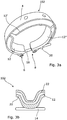
- clamping apparatus in the form of a V-Clamp 2 for clamping together the ends of two conduits used for the flow of hot gases therealong, such as for example exhaust gases, in use.
- the V-Clamp 2 comprises two clamping members; an outer band 4 which is annular in form having two opposing ends 6, 8, each end 6, 8 having a loop portion14, 16 associated with the same; and an inner band formed from three segments 12, 12', 12". (Although three segments are shown in the figure, any number of segments could be provided). The three segments 12-12" are joined in an end to end manner with a space between each of the ends. The three segments have a V-shaped cross sectional profile and are joined to the inner surface of the outer band 4.
- Each end 6, 8 of the outer band 4 is provided with a strap portion 14, 16 respectively for the location of adjustment means in the form of a trunnion 18 and a nut 20.
- the adjustment means allows the distance between the free ends 6, 8 and the straps 14, 16 to be adjusted, thereby increasing or decreasing the size of the band aperture and allowing the clamp 2 to be moved between an unclamped position, wherein the clamp 2 can be located over or removed from two overlapping conduits and the ends are a relatively large spaced distance apart, and a clamped position, wherein the clamp is clamped around two overlapping conduits and the ends are adjacent to each other or a relatively small spaced distance apart.
- the conduits which are being clamped are arranged to allow hot exhaust gases to flow through channels defined in the same.
- heat insulating means in the form of a zirconium oxide layer 22 is provided on the inner surface of the three segments 12, 12', 12"that face towards the conduit.
- the zirconium oxide layer has a thermal conductance of approximately 1.0-1.4 W/mK, thereby preventing heat from passing from the conduits to the clamp in use.
- the zirconium oxide layer is typically provided at a thickness of 0.3-0.5mm on the segments. However, any suitable thermal conductance or thickness of the thermal insulating means could be provided so as to provide a thermal insulating effect.
- the zirconium oxide layer is applied to the inner surface of the inner clamping member segments 12-12" using a High Velocity Oxy-Fuel spray technique but any suitable technique could be used.
- the zirconium oxide layer is directly in contact with the outer surface of the outer conduit in use, thereby thermally insulates the clamp from the gases/fluids flowing in the conduits in use.
- the zirconium oxide layer may be indirectly in contact with the outer surface of the outer conduit in use if sealing means for example where also provided between the zirconium oxide layer and the outer conduit surface.
- the zirconium oxide layer retains the heat of the hot gases/fluids within the conduit, thereby maintaining the volumetric flow of the gases/fluid along the conduits in use.
- FIG. 1b shows a further example of V-clamp 2 according to an embodiment of the present invention wherein an intermediate band 10 is provided between the outer band 4 and the inner band segments 12-12".
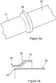
- FIGS. 2a-2b there is illustrated an example of two items in the form of conduits 24, 26 that could be joined together by clamping apparatus, such as for example by the V-clamp shown in Figures 1a-1b in use.
- conduit 24 is provided with an outwardly extending flange portion 28 and the end 30 of conduit 26 is located in the channel of conduit 24.
- the outer surface of the flange portion 28 is provided with a heat or thermal insulating zirconium oxide layer 22.
- the provision of the heat insulating layer on the outer surface of the flange portion 28 of the conduit 24 provides the same benefits as the heat insulating layer being provided on the inner surface of the innermost clamping member.
- a heat or thermal insulating layer is provided between the contacting surfaces of the conduit and clamping member to prevent heat from being transferred from the conduit to the clamping member and vice versa in use.
- clamping apparatus 102 according to a further embodiment of the present invention in the form of a V-clamp.
- the same reference numerals are used to describe the same features as previously described.
- the V-clamp 102 is similar in form to the V-clamp shown in figure 1a with the exception that thermal insulating means, in the form of a zirconium oxide layer, is provided on the inner surface and the outer surface of the inner band segments 12.
- clamping apparatus 202 according to a yet further embodiment of the present invention in the form of a V-clamp.
- the same reference numerals are used to describe the same features as previously described.
- the V-clamp 202 is similar in form to the V-clamp shown in figures 1a , 3a and 3b with the exception that thermal insulating means, in the form of a zirconium oxide layer, is provided on the inner surface and the outer surface of the inner band segments 12, in addition to the inner and outer surfaces of the outer band 4.
- thermal insulating means in the form of a zirconium oxide layer
Landscapes
- Engineering & Computer Science (AREA)
- General Engineering & Computer Science (AREA)
- Mechanical Engineering (AREA)
- Chemical & Material Sciences (AREA)
- Combustion & Propulsion (AREA)
- Thermal Insulation (AREA)
- Clamps And Clips (AREA)
Claims (14)
- Klemmvorrichtung (2, 102, 202) zum Aneinanderklemmen von zwei oder mehr Artikeln (24, 26) im Gebrauch, wobei die genannte Klemmvorrichtung (2, 102, 202) mindestens ein Klemmelement mit einer einwärts gerichteten Oberfläche oder einer Innenfläche aufweist, die angeordnet ist, um mit einer Außenfläche von mindestens einem der Artikel (24, 26), die im Gebrauch geklemmt werden, direkt oder indirekt in Kontakt gebracht zu werden,
und dadurch gekennzeichnet, dass Wärmedämmungsmittel (22) in bzw. als eine ununterbrochene(n) Schicht oder Beschichtung auf der gesamten einwärts gerichteten Oberfläche oder Innenfläche des mindestens einen Klemmelements integriert oder vorgesehen sind. - Klemmvorrichtung nach Anspruch 1, wobei das Wärmedämmungsmittel aus einem beliebigen Material oder einer beliebigen Kombination von Materialien hergestellt ist, das/die einen Wärmedämmungseffekt bei Temperaturen von 500 °C oder darüber bietet;wobei das Wärmedämmungsmittel aus einem beliebigen Material oder einer beliebigen Kombination von Materialien hergestellt ist, das/die einen Wärmeübergang über dasselbe von weniger als 5 W/mK zulässt; und/oderwobei das Wärmedämmungsmittel (aus einem) Zirkonoxid oder Zirkon-Keramik besteht oder beinhaltet.
- Klemmvorrichtung nach Anspruch 1 oder 2, wobei das Wärmedämmungsmittel mit einer Dicke zwischen 0,3 mm und 0,5 mm versehen ist.
- Klemmvorrichtung nach Anspruch 1, wobei das Wärmedämmungsmittel auch an bzw. in bzw. mit einer Außenfläche des mindesten einen Klemmelements vorgesehen, integriert oder assoziiert ist.
- Klemmvorrichtung nach Anspruch 1, wobei, wenn das mindestens eine Klemmelement ein äußeres Bandelement (4) und ein inneres Bandelement oder innere Bandelementsegmente (12, 12', 12") aufweist, das Wärmedämmungsmittel an bzw. in der/die einwärts gerichtete(n) innere(n) oder der/die innerste(n) Oberfläche des inneren Bandelements oder den/die inneren Bandelementsegmente(n) (12, 12', 12") vorgesehen oder integriert ist.
- Klemmvorrichtung nach Anspruch 5, wobei das Wärmedämmungsmittel auch an bzw. in bzw. mit der/die äußere(n) Oberfläche des inneren Bandelements oder den/die inneren Bandelementsegmente(n) (12, 12', 12"), der/die Innenfläche des äußeren Bandelements (4) und/oder die/der äußere(n) Oberfläche des äußeren Bandelements (4) vorgesehen, integriert oder assoziiert ist.
- Klemmvorrichtung nach Anspruch 1 in der Form von oder mit einer Rohrschelle, einer Ringklemme, einer Bandklemme, einer G-Kupplung, einer Gleitverbindung und/oder einem Flansch.
- Klemmvorrichtung nach Anspruch 1, wobei die Innenfläche des mindestens einen Klemmelements und/oder der Außenfläche des mindestens einen Artikels (24, 26) mit Profil versehen oder nicht ebenflächig ist.
- Klemmvorrichtung nach Anspruch 1, wobei das mindestens eine Klemmelement, ein äußeres Bandelement (4) und/oder ein inneres Bandelement oder innere Bandelementsegmente (12, 12', 12") ringförmig oder im Wesentlichen ringförmig ist bzw. sind.
- Klemmvorrichtung nach Anspruch 1, wobei die Vorrichtung (2, 102, 202) und/oder das mindestens eine Klemmelement zwischen einer geklemmten Stellung, wobei das Klemmelement im Gebrauch zwei oder mehr Artikel (24, 26) aneinanderklemmen kann, und einer ungeklemmten Stellung, wobei die zwei oder mehr Artikel (24, 26) im Gebrauch in bzw. aus der Klemmvorrichtung (2, 102, 202) positioniert oder entfernt werden können, bewegbar ist; und wobei Einstellmittel zum Ermöglichen, dass die Klemmvorrichtung (2, 102, 202) und/oder das mindestens eine Klemmelement im Gebrauch zwischen der geklemmten und der ungeklemmten Stellung bewegt werden, vorgesehen sind.
- Klemmvorrichtung nach Anspruch 10, wobei das Einstellmittel beliebige oder eine beliebige Kombination von ein oder mehr Zapfen (18), Gewindezapfen, Muttern (20), Schrauben, Gewindestiften, Clips oder ineinandergreifenden Elementen aufweist.
- Vorrichtung nach Anspruch 1, wobei Dichtungsmittel mit der Klemmvorrichtung (2, 102, 202) versehen oder assoziiert sind.
- Verfahren zur Verwendung der Klemmvorrichtung (2, 102, 202) nach einem der Ansprüche 1 bis 12 zum Aneinanderklemmen von zwei oder mehr Artikeln (24, 26), wobei das genannte Verfahren den Schritt des Bewegens von mindestens einer Innenfläche von mindestens einem Klemmelement in direkten oder indirekten Kontakt mit einer Außenfläche von mindestens einem der Artikel (24, 26), der geklemmt wird, aufweist, dadurch gekennzeichnet, dass Wärmedämmungsmittel (22) in eine bzw. als eine ununterbrochene Schicht oder Beschichtung auf einer gesamten einwärts gerichteten Oberfläche oder Innenfläche des mindestens einen Klemmelements integriert oder vorgesehen sind.
- Verfahren nach Anspruch 13, wobei das Wärmedämmungsmittel unter Verwendung von Technologie der Plasma-unterstützten Sputterbeschichtung oder Hochgeschwindigkeits-Suspensionsflammspritz-Technologie auf mindestens eine Oberfläche des mindestens einen Klemmelements aufgebracht wird.
Applications Claiming Priority (2)
| Application Number | Priority Date | Filing Date | Title |
|---|---|---|---|
| GBGB1700197.5A GB201700197D0 (en) | 2017-01-06 | 2017-01-06 | Clamping apparatus and method os use and/or manufacture thereof |
| PCT/GB2018/050018 WO2018127700A1 (en) | 2017-01-06 | 2018-01-05 | Clamping appratus and method of use and/or manufacturing thereof |
Publications (2)
| Publication Number | Publication Date |
|---|---|
| EP3548790A1 EP3548790A1 (de) | 2019-10-09 |
| EP3548790B1 true EP3548790B1 (de) | 2021-12-29 |
Family
ID=58463787
Family Applications (1)
| Application Number | Title | Priority Date | Filing Date |
|---|---|---|---|
| EP18701526.8A Active EP3548790B1 (de) | 2017-01-06 | 2018-01-05 | Klemmvorrichtung und verfahren zur verwendung davon |
Country Status (5)
| Country | Link |
|---|---|
| US (1) | US20190353080A1 (de) |
| EP (1) | EP3548790B1 (de) |
| CN (1) | CN110291321A (de) |
| GB (1) | GB201700197D0 (de) |
| WO (1) | WO2018127700A1 (de) |
Families Citing this family (4)
| Publication number | Priority date | Publication date | Assignee | Title |
|---|---|---|---|---|
| WO2021076774A1 (en) * | 2019-10-15 | 2021-04-22 | Saprex, Llc | Exhaust insulation system |
| CN113154157A (zh) * | 2021-03-16 | 2021-07-23 | 中国航发哈尔滨东安发动机有限公司 | 一种端面法兰快速装卸装置 |
| US12173832B2 (en) * | 2021-05-13 | 2024-12-24 | Lincoln Industries, Inc. | Clamp insulation systems and methods |
| WO2026054640A1 (en) | 2024-09-03 | 2026-03-12 | Dinex Latvia, Sia | A thermaly insultaed clamp |
Family Cites Families (6)
| Publication number | Priority date | Publication date | Assignee | Title |
|---|---|---|---|---|
| JPH03292489A (ja) * | 1990-04-05 | 1991-12-24 | Nissan Motor Co Ltd | Vバンドシール構造 |
| JPH0893976A (ja) * | 1994-09-22 | 1996-04-12 | Toyota Motor Corp | 管の継ぎ手装置 |
| US6070911A (en) * | 1999-03-01 | 2000-06-06 | Jgc Corporation | Clamp-type pipe joint |
| US8017230B2 (en) * | 2005-10-31 | 2011-09-13 | Praxair S.T. Technology, Inc. | Ceramic powders and thermal barrier coatings made therefrom |
| WO2011041448A2 (en) * | 2009-09-29 | 2011-04-07 | Cummins Ip, Inc. | Spherical flange joint |
| DE102013114080A1 (de) * | 2013-12-16 | 2015-06-18 | Norma Germany Gmbh | Element einer Schellen-Flansch-Verbindung |
-
2017
- 2017-01-06 GB GBGB1700197.5A patent/GB201700197D0/en not_active Ceased
-
2018
- 2018-01-05 US US16/475,837 patent/US20190353080A1/en not_active Abandoned
- 2018-01-05 EP EP18701526.8A patent/EP3548790B1/de active Active
- 2018-01-05 WO PCT/GB2018/050018 patent/WO2018127700A1/en not_active Ceased
- 2018-01-05 CN CN201880006235.8A patent/CN110291321A/zh active Pending
Also Published As
| Publication number | Publication date |
|---|---|
| GB201700197D0 (en) | 2017-02-22 |
| WO2018127700A1 (en) | 2018-07-12 |
| CN110291321A (zh) | 2019-09-27 |
| EP3548790A1 (de) | 2019-10-09 |
| US20190353080A1 (en) | 2019-11-21 |
Similar Documents
| Publication | Publication Date | Title |
|---|---|---|
| EP3548790B1 (de) | Klemmvorrichtung und verfahren zur verwendung davon | |
| US7735875B2 (en) | Device and method for making and using a pipe coupling device | |
| KR100482386B1 (ko) | 다층식유체도관시스템및그제조방법 | |
| US4838477A (en) | Method of welding flanged pipe sections and apparatus therefor | |
| US5669812A (en) | Exhaust gas diffuser interface | |
| US7243409B2 (en) | Weldable conduit method of forming | |
| US8658071B2 (en) | Method for lining a pipe or elbow | |
| US6000435A (en) | Reinforced hose and retainer ring assembly | |
| US5775379A (en) | Insulation jacket for fluid carrying conduits | |
| WO2005008116A2 (en) | System and method for coupling conduit | |
| SA517390362B1 (ar) | توصيل مقاطع أنبوبية مبطَّنة | |
| US20170030503A1 (en) | Apparatus and method for securing pipe heaters and pipe insulation to pipe systems | |
| US4313625A (en) | Lined pipe assembly | |
| US3984131A (en) | Packing gland for TiCl4 inlet to oxidizer reactor | |
| US20060016579A1 (en) | Profile traced insulated cover assembly | |
| RU2389943C1 (ru) | Теплоизолированный стык предварительно теплоизолированных труб с полимерной оболочкой, способ его монтажа, полимерная муфта и способ ее изготовления | |
| US20050006899A1 (en) | Weldable conduit and method | |
| US20120056419A1 (en) | Pipe coupling | |
| WO2012118431A1 (en) | Pipe unit in a conduit for a gaseous medium | |
| US10995883B1 (en) | Penetration seal system and methods | |
| CN213333099U (zh) | 管道及管道系统 | |
| FI92098C (fi) | Eristysputkikanavajärjestelmä | |
| WO2017216105A1 (en) | Vehicle exhaust system | |
| EP0019895A1 (de) | Verbindung für ausgekleidete Rohrleitung | |
| TWI871930B (zh) | 管線保溫材料的施工方法 |
Legal Events
| Date | Code | Title | Description |
|---|---|---|---|
| STAA | Information on the status of an ep patent application or granted ep patent |
Free format text: STATUS: UNKNOWN |
|
| STAA | Information on the status of an ep patent application or granted ep patent |
Free format text: STATUS: THE INTERNATIONAL PUBLICATION HAS BEEN MADE |
|
| PUAI | Public reference made under article 153(3) epc to a published international application that has entered the european phase |
Free format text: ORIGINAL CODE: 0009012 |
|
| STAA | Information on the status of an ep patent application or granted ep patent |
Free format text: STATUS: REQUEST FOR EXAMINATION WAS MADE |
|
| 17P | Request for examination filed |
Effective date: 20190705 |
|
| AK | Designated contracting states |
Kind code of ref document: A1 Designated state(s): AL AT BE BG CH CY CZ DE DK EE ES FI FR GB GR HR HU IE IS IT LI LT LU LV MC MK MT NL NO PL PT RO RS SE SI SK SM TR |
|
| AX | Request for extension of the european patent |
Extension state: BA ME |
|
| DAV | Request for validation of the european patent (deleted) | ||
| DAX | Request for extension of the european patent (deleted) | ||
| RIC1 | Information provided on ipc code assigned before grant |
Ipc: F01N 13/18 20100101ALI20210714BHEP Ipc: F16L 58/18 20060101ALI20210714BHEP Ipc: F16L 23/08 20060101ALI20210714BHEP Ipc: F01N 13/14 20100101ALI20210714BHEP Ipc: F16L 59/18 20060101ALI20210714BHEP Ipc: F16L 37/12 20060101ALI20210714BHEP Ipc: F16L 58/14 20060101AFI20210714BHEP |
|
| GRAP | Despatch of communication of intention to grant a patent |
Free format text: ORIGINAL CODE: EPIDOSNIGR1 |
|
| STAA | Information on the status of an ep patent application or granted ep patent |
Free format text: STATUS: GRANT OF PATENT IS INTENDED |
|
| INTG | Intention to grant announced |
Effective date: 20210924 |
|
| RIN1 | Information on inventor provided before grant (corrected) |
Inventor name: BROWN, IAN |
|
| GRAS | Grant fee paid |
Free format text: ORIGINAL CODE: EPIDOSNIGR3 |
|
| GRAA | (expected) grant |
Free format text: ORIGINAL CODE: 0009210 |
|
| STAA | Information on the status of an ep patent application or granted ep patent |
Free format text: STATUS: THE PATENT HAS BEEN GRANTED |
|
| AK | Designated contracting states |
Kind code of ref document: B1 Designated state(s): AL AT BE BG CH CY CZ DE DK EE ES FI FR GB GR HR HU IE IS IT LI LT LU LV MC MK MT NL NO PL PT RO RS SE SI SK SM TR |
|
| REG | Reference to a national code |
Ref country code: GB Ref legal event code: FG4D |
|
| REG | Reference to a national code |
Ref country code: CH Ref legal event code: EP |
|
| REG | Reference to a national code |
Ref country code: AT Ref legal event code: REF Ref document number: 1458930 Country of ref document: AT Kind code of ref document: T Effective date: 20220115 |
|
| REG | Reference to a national code |
Ref country code: IE Ref legal event code: FG4D |
|
| REG | Reference to a national code |
Ref country code: DE Ref legal event code: R096 Ref document number: 602018028752 Country of ref document: DE |
|
| REG | Reference to a national code |
Ref country code: LT Ref legal event code: MG9D |
|
| PG25 | Lapsed in a contracting state [announced via postgrant information from national office to epo] |
Ref country code: RS Free format text: LAPSE BECAUSE OF FAILURE TO SUBMIT A TRANSLATION OF THE DESCRIPTION OR TO PAY THE FEE WITHIN THE PRESCRIBED TIME-LIMIT Effective date: 20211229 Ref country code: LT Free format text: LAPSE BECAUSE OF FAILURE TO SUBMIT A TRANSLATION OF THE DESCRIPTION OR TO PAY THE FEE WITHIN THE PRESCRIBED TIME-LIMIT Effective date: 20211229 Ref country code: FI Free format text: LAPSE BECAUSE OF FAILURE TO SUBMIT A TRANSLATION OF THE DESCRIPTION OR TO PAY THE FEE WITHIN THE PRESCRIBED TIME-LIMIT Effective date: 20211229 Ref country code: BG Free format text: LAPSE BECAUSE OF FAILURE TO SUBMIT A TRANSLATION OF THE DESCRIPTION OR TO PAY THE FEE WITHIN THE PRESCRIBED TIME-LIMIT Effective date: 20220329 |
|
| REG | Reference to a national code |
Ref country code: NL Ref legal event code: MP Effective date: 20211229 |
|
| REG | Reference to a national code |
Ref country code: AT Ref legal event code: MK05 Ref document number: 1458930 Country of ref document: AT Kind code of ref document: T Effective date: 20211229 |
|
| PG25 | Lapsed in a contracting state [announced via postgrant information from national office to epo] |
Ref country code: SE Free format text: LAPSE BECAUSE OF FAILURE TO SUBMIT A TRANSLATION OF THE DESCRIPTION OR TO PAY THE FEE WITHIN THE PRESCRIBED TIME-LIMIT Effective date: 20211229 Ref country code: NO Free format text: LAPSE BECAUSE OF FAILURE TO SUBMIT A TRANSLATION OF THE DESCRIPTION OR TO PAY THE FEE WITHIN THE PRESCRIBED TIME-LIMIT Effective date: 20220329 Ref country code: LV Free format text: LAPSE BECAUSE OF FAILURE TO SUBMIT A TRANSLATION OF THE DESCRIPTION OR TO PAY THE FEE WITHIN THE PRESCRIBED TIME-LIMIT Effective date: 20211229 Ref country code: HR Free format text: LAPSE BECAUSE OF FAILURE TO SUBMIT A TRANSLATION OF THE DESCRIPTION OR TO PAY THE FEE WITHIN THE PRESCRIBED TIME-LIMIT Effective date: 20211229 Ref country code: GR Free format text: LAPSE BECAUSE OF FAILURE TO SUBMIT A TRANSLATION OF THE DESCRIPTION OR TO PAY THE FEE WITHIN THE PRESCRIBED TIME-LIMIT Effective date: 20220330 |
|
| PG25 | Lapsed in a contracting state [announced via postgrant information from national office to epo] |
Ref country code: NL Free format text: LAPSE BECAUSE OF FAILURE TO SUBMIT A TRANSLATION OF THE DESCRIPTION OR TO PAY THE FEE WITHIN THE PRESCRIBED TIME-LIMIT Effective date: 20211229 |
|
| PG25 | Lapsed in a contracting state [announced via postgrant information from national office to epo] |
Ref country code: SM Free format text: LAPSE BECAUSE OF FAILURE TO SUBMIT A TRANSLATION OF THE DESCRIPTION OR TO PAY THE FEE WITHIN THE PRESCRIBED TIME-LIMIT Effective date: 20211229 Ref country code: SK Free format text: LAPSE BECAUSE OF FAILURE TO SUBMIT A TRANSLATION OF THE DESCRIPTION OR TO PAY THE FEE WITHIN THE PRESCRIBED TIME-LIMIT Effective date: 20211229 Ref country code: RO Free format text: LAPSE BECAUSE OF FAILURE TO SUBMIT A TRANSLATION OF THE DESCRIPTION OR TO PAY THE FEE WITHIN THE PRESCRIBED TIME-LIMIT Effective date: 20211229 Ref country code: PT Free format text: LAPSE BECAUSE OF FAILURE TO SUBMIT A TRANSLATION OF THE DESCRIPTION OR TO PAY THE FEE WITHIN THE PRESCRIBED TIME-LIMIT Effective date: 20220429 Ref country code: ES Free format text: LAPSE BECAUSE OF FAILURE TO SUBMIT A TRANSLATION OF THE DESCRIPTION OR TO PAY THE FEE WITHIN THE PRESCRIBED TIME-LIMIT Effective date: 20211229 Ref country code: EE Free format text: LAPSE BECAUSE OF FAILURE TO SUBMIT A TRANSLATION OF THE DESCRIPTION OR TO PAY THE FEE WITHIN THE PRESCRIBED TIME-LIMIT Effective date: 20211229 Ref country code: CZ Free format text: LAPSE BECAUSE OF FAILURE TO SUBMIT A TRANSLATION OF THE DESCRIPTION OR TO PAY THE FEE WITHIN THE PRESCRIBED TIME-LIMIT Effective date: 20211229 |
|
| PG25 | Lapsed in a contracting state [announced via postgrant information from national office to epo] |
Ref country code: PL Free format text: LAPSE BECAUSE OF FAILURE TO SUBMIT A TRANSLATION OF THE DESCRIPTION OR TO PAY THE FEE WITHIN THE PRESCRIBED TIME-LIMIT Effective date: 20211229 Ref country code: AT Free format text: LAPSE BECAUSE OF FAILURE TO SUBMIT A TRANSLATION OF THE DESCRIPTION OR TO PAY THE FEE WITHIN THE PRESCRIBED TIME-LIMIT Effective date: 20211229 |
|
| REG | Reference to a national code |
Ref country code: CH Ref legal event code: PL |
|
| PG25 | Lapsed in a contracting state [announced via postgrant information from national office to epo] |
Ref country code: MC Free format text: LAPSE BECAUSE OF FAILURE TO SUBMIT A TRANSLATION OF THE DESCRIPTION OR TO PAY THE FEE WITHIN THE PRESCRIBED TIME-LIMIT Effective date: 20211229 Ref country code: IS Free format text: LAPSE BECAUSE OF FAILURE TO SUBMIT A TRANSLATION OF THE DESCRIPTION OR TO PAY THE FEE WITHIN THE PRESCRIBED TIME-LIMIT Effective date: 20220429 |
|
| REG | Reference to a national code |
Ref country code: DE Ref legal event code: R097 Ref document number: 602018028752 Country of ref document: DE |
|
| REG | Reference to a national code |
Ref country code: BE Ref legal event code: MM Effective date: 20220131 |
|
| PG25 | Lapsed in a contracting state [announced via postgrant information from national office to epo] |
Ref country code: LU Free format text: LAPSE BECAUSE OF NON-PAYMENT OF DUE FEES Effective date: 20220105 Ref country code: DK Free format text: LAPSE BECAUSE OF FAILURE TO SUBMIT A TRANSLATION OF THE DESCRIPTION OR TO PAY THE FEE WITHIN THE PRESCRIBED TIME-LIMIT Effective date: 20211229 Ref country code: AL Free format text: LAPSE BECAUSE OF FAILURE TO SUBMIT A TRANSLATION OF THE DESCRIPTION OR TO PAY THE FEE WITHIN THE PRESCRIBED TIME-LIMIT Effective date: 20211229 |
|
| PLBE | No opposition filed within time limit |
Free format text: ORIGINAL CODE: 0009261 |
|
| STAA | Information on the status of an ep patent application or granted ep patent |
Free format text: STATUS: NO OPPOSITION FILED WITHIN TIME LIMIT |
|
| PG25 | Lapsed in a contracting state [announced via postgrant information from national office to epo] |
Ref country code: BE Free format text: LAPSE BECAUSE OF NON-PAYMENT OF DUE FEES Effective date: 20220131 |
|
| 26N | No opposition filed |
Effective date: 20220930 |
|
| PG25 | Lapsed in a contracting state [announced via postgrant information from national office to epo] |
Ref country code: LI Free format text: LAPSE BECAUSE OF NON-PAYMENT OF DUE FEES Effective date: 20220131 Ref country code: CH Free format text: LAPSE BECAUSE OF NON-PAYMENT OF DUE FEES Effective date: 20220131 |
|
| PG25 | Lapsed in a contracting state [announced via postgrant information from national office to epo] |
Ref country code: IE Free format text: LAPSE BECAUSE OF NON-PAYMENT OF DUE FEES Effective date: 20220105 |
|
| PG25 | Lapsed in a contracting state [announced via postgrant information from national office to epo] |
Ref country code: SI Free format text: LAPSE BECAUSE OF FAILURE TO SUBMIT A TRANSLATION OF THE DESCRIPTION OR TO PAY THE FEE WITHIN THE PRESCRIBED TIME-LIMIT Effective date: 20211229 |
|
| PG25 | Lapsed in a contracting state [announced via postgrant information from national office to epo] |
Ref country code: IT Free format text: LAPSE BECAUSE OF FAILURE TO SUBMIT A TRANSLATION OF THE DESCRIPTION OR TO PAY THE FEE WITHIN THE PRESCRIBED TIME-LIMIT Effective date: 20211229 |
|
| P01 | Opt-out of the competence of the unified patent court (upc) registered |
Effective date: 20230403 |
|
| PG25 | Lapsed in a contracting state [announced via postgrant information from national office to epo] |
Ref country code: MK Free format text: LAPSE BECAUSE OF FAILURE TO SUBMIT A TRANSLATION OF THE DESCRIPTION OR TO PAY THE FEE WITHIN THE PRESCRIBED TIME-LIMIT Effective date: 20211229 Ref country code: CY Free format text: LAPSE BECAUSE OF FAILURE TO SUBMIT A TRANSLATION OF THE DESCRIPTION OR TO PAY THE FEE WITHIN THE PRESCRIBED TIME-LIMIT Effective date: 20211229 |
|
| PG25 | Lapsed in a contracting state [announced via postgrant information from national office to epo] |
Ref country code: HU Free format text: LAPSE BECAUSE OF FAILURE TO SUBMIT A TRANSLATION OF THE DESCRIPTION OR TO PAY THE FEE WITHIN THE PRESCRIBED TIME-LIMIT; INVALID AB INITIO Effective date: 20180105 |
|
| PG25 | Lapsed in a contracting state [announced via postgrant information from national office to epo] |
Ref country code: MT Free format text: LAPSE BECAUSE OF FAILURE TO SUBMIT A TRANSLATION OF THE DESCRIPTION OR TO PAY THE FEE WITHIN THE PRESCRIBED TIME-LIMIT Effective date: 20211229 |
|
| PGFP | Annual fee paid to national office [announced via postgrant information from national office to epo] |
Ref country code: DE Payment date: 20241127 Year of fee payment: 8 |
|
| PG25 | Lapsed in a contracting state [announced via postgrant information from national office to epo] |
Ref country code: TR Free format text: LAPSE BECAUSE OF FAILURE TO SUBMIT A TRANSLATION OF THE DESCRIPTION OR TO PAY THE FEE WITHIN THE PRESCRIBED TIME-LIMIT Effective date: 20211229 |
|
| PGFP | Annual fee paid to national office [announced via postgrant information from national office to epo] |
Ref country code: GB Payment date: 20251209 Year of fee payment: 9 |
|
| PGFP | Annual fee paid to national office [announced via postgrant information from national office to epo] |
Ref country code: FR Payment date: 20251209 Year of fee payment: 9 |