EP3548734B1 - Mastlose windturbine zur stromerzeugung - Google Patents
Mastlose windturbine zur stromerzeugung Download PDFInfo
- Publication number
- EP3548734B1 EP3548734B1 EP17876489.0A EP17876489A EP3548734B1 EP 3548734 B1 EP3548734 B1 EP 3548734B1 EP 17876489 A EP17876489 A EP 17876489A EP 3548734 B1 EP3548734 B1 EP 3548734B1
- Authority
- EP
- European Patent Office
- Prior art keywords
- sails
- vertical axis
- mastless
- wind turbine
- turbine
- Prior art date
- Legal status (The legal status is an assumption and is not a legal conclusion. Google has not performed a legal analysis and makes no representation as to the accuracy of the status listed.)
- Active
Links
Images


Classifications
-
- F—MECHANICAL ENGINEERING; LIGHTING; HEATING; WEAPONS; BLASTING
- F03—MACHINES OR ENGINES FOR LIQUIDS; WIND, SPRING, OR WEIGHT MOTORS; PRODUCING MECHANICAL POWER OR A REACTIVE PROPULSIVE THRUST, NOT OTHERWISE PROVIDED FOR
- F03D—WIND MOTORS
- F03D3/00—Wind motors with rotation axis substantially perpendicular to the air flow entering the rotor
- F03D3/005—Wind motors with rotation axis substantially perpendicular to the air flow entering the rotor the axis being vertical
-
- F—MECHANICAL ENGINEERING; LIGHTING; HEATING; WEAPONS; BLASTING
- F03—MACHINES OR ENGINES FOR LIQUIDS; WIND, SPRING, OR WEIGHT MOTORS; PRODUCING MECHANICAL POWER OR A REACTIVE PROPULSIVE THRUST, NOT OTHERWISE PROVIDED FOR
- F03D—WIND MOTORS
- F03D3/00—Wind motors with rotation axis substantially perpendicular to the air flow entering the rotor
- F03D3/06—Rotors
- F03D3/062—Rotors characterised by their construction elements
- F03D3/064—Fixing wind engaging parts to rest of rotor
-
- F—MECHANICAL ENGINEERING; LIGHTING; HEATING; WEAPONS; BLASTING
- F03—MACHINES OR ENGINES FOR LIQUIDS; WIND, SPRING, OR WEIGHT MOTORS; PRODUCING MECHANICAL POWER OR A REACTIVE PROPULSIVE THRUST, NOT OTHERWISE PROVIDED FOR
- F03D—WIND MOTORS
- F03D9/00—Adaptations of wind motors for special use; Combinations of wind motors with apparatus driven thereby; Wind motors specially adapted for installation in particular locations
- F03D9/10—Combinations of wind motors with apparatus storing energy
- F03D9/11—Combinations of wind motors with apparatus storing energy storing electrical energy
-
- F—MECHANICAL ENGINEERING; LIGHTING; HEATING; WEAPONS; BLASTING
- F03—MACHINES OR ENGINES FOR LIQUIDS; WIND, SPRING, OR WEIGHT MOTORS; PRODUCING MECHANICAL POWER OR A REACTIVE PROPULSIVE THRUST, NOT OTHERWISE PROVIDED FOR
- F03D—WIND MOTORS
- F03D9/00—Adaptations of wind motors for special use; Combinations of wind motors with apparatus driven thereby; Wind motors specially adapted for installation in particular locations
- F03D9/20—Wind motors characterised by the driven apparatus
- F03D9/25—Wind motors characterised by the driven apparatus the apparatus being an electrical generator
-
- F—MECHANICAL ENGINEERING; LIGHTING; HEATING; WEAPONS; BLASTING
- F05—INDEXING SCHEMES RELATING TO ENGINES OR PUMPS IN VARIOUS SUBCLASSES OF CLASSES F01-F04
- F05B—INDEXING SCHEME RELATING TO WIND, SPRING, WEIGHT, INERTIA OR LIKE MOTORS, TO MACHINES OR ENGINES FOR LIQUIDS COVERED BY SUBCLASSES F03B, F03D AND F03G
- F05B2210/00—Working fluid
- F05B2210/16—Air or water being indistinctly used as working fluid, i.e. the machine can work equally with air or water without any modification
-
- F—MECHANICAL ENGINEERING; LIGHTING; HEATING; WEAPONS; BLASTING
- F05—INDEXING SCHEMES RELATING TO ENGINES OR PUMPS IN VARIOUS SUBCLASSES OF CLASSES F01-F04
- F05B—INDEXING SCHEME RELATING TO WIND, SPRING, WEIGHT, INERTIA OR LIKE MOTORS, TO MACHINES OR ENGINES FOR LIQUIDS COVERED BY SUBCLASSES F03B, F03D AND F03G
- F05B2240/00—Components
- F05B2240/20—Rotors
- F05B2240/21—Rotors for wind turbines
- F05B2240/211—Rotors for wind turbines with vertical axis
-
- F—MECHANICAL ENGINEERING; LIGHTING; HEATING; WEAPONS; BLASTING
- F05—INDEXING SCHEMES RELATING TO ENGINES OR PUMPS IN VARIOUS SUBCLASSES OF CLASSES F01-F04
- F05B—INDEXING SCHEME RELATING TO WIND, SPRING, WEIGHT, INERTIA OR LIKE MOTORS, TO MACHINES OR ENGINES FOR LIQUIDS COVERED BY SUBCLASSES F03B, F03D AND F03G
- F05B2240/00—Components
- F05B2240/20—Rotors
- F05B2240/30—Characteristics of rotor blades, i.e. of any element transforming dynamic fluid energy to or from rotational energy and being attached to a rotor
- F05B2240/31—Characteristics of rotor blades, i.e. of any element transforming dynamic fluid energy to or from rotational energy and being attached to a rotor of changeable form or shape
- F05B2240/311—Characteristics of rotor blades, i.e. of any element transforming dynamic fluid energy to or from rotational energy and being attached to a rotor of changeable form or shape flexible or elastic
-
- Y—GENERAL TAGGING OF NEW TECHNOLOGICAL DEVELOPMENTS; GENERAL TAGGING OF CROSS-SECTIONAL TECHNOLOGIES SPANNING OVER SEVERAL SECTIONS OF THE IPC; TECHNICAL SUBJECTS COVERED BY FORMER USPC CROSS-REFERENCE ART COLLECTIONS [XRACs] AND DIGESTS
- Y02—TECHNOLOGIES OR APPLICATIONS FOR MITIGATION OR ADAPTATION AGAINST CLIMATE CHANGE
- Y02B—CLIMATE CHANGE MITIGATION TECHNOLOGIES RELATED TO BUILDINGS, e.g. HOUSING, HOUSE APPLIANCES OR RELATED END-USER APPLICATIONS
- Y02B10/00—Integration of renewable energy sources in buildings
- Y02B10/30—Wind power
-
- Y—GENERAL TAGGING OF NEW TECHNOLOGICAL DEVELOPMENTS; GENERAL TAGGING OF CROSS-SECTIONAL TECHNOLOGIES SPANNING OVER SEVERAL SECTIONS OF THE IPC; TECHNICAL SUBJECTS COVERED BY FORMER USPC CROSS-REFERENCE ART COLLECTIONS [XRACs] AND DIGESTS
- Y02—TECHNOLOGIES OR APPLICATIONS FOR MITIGATION OR ADAPTATION AGAINST CLIMATE CHANGE
- Y02E—REDUCTION OF GREENHOUSE GAS [GHG] EMISSIONS, RELATED TO ENERGY GENERATION, TRANSMISSION OR DISTRIBUTION
- Y02E10/00—Energy generation through renewable energy sources
- Y02E10/70—Wind energy
- Y02E10/74—Wind turbines with rotation axis perpendicular to the wind direction
-
- Y—GENERAL TAGGING OF NEW TECHNOLOGICAL DEVELOPMENTS; GENERAL TAGGING OF CROSS-SECTIONAL TECHNOLOGIES SPANNING OVER SEVERAL SECTIONS OF THE IPC; TECHNICAL SUBJECTS COVERED BY FORMER USPC CROSS-REFERENCE ART COLLECTIONS [XRACs] AND DIGESTS
- Y02—TECHNOLOGIES OR APPLICATIONS FOR MITIGATION OR ADAPTATION AGAINST CLIMATE CHANGE
- Y02E—REDUCTION OF GREENHOUSE GAS [GHG] EMISSIONS, RELATED TO ENERGY GENERATION, TRANSMISSION OR DISTRIBUTION
- Y02E70/00—Other energy conversion or management systems reducing GHG emissions
- Y02E70/30—Systems combining energy storage with energy generation of non-fossil origin
Definitions
- known vertical axis wind turbines utilize blades and/or wheels that can be heavy, unsightly, dangerous to wildlife, and difficult to transport. Rotation of the heavy blades and/or wheels can cause damage to surrounding objects, such as animals, as well as the blades and/or wheels themselves.
- WO 2014/195640 describes a vertical axis wind turbine.
- US 4, 708, 592 provides a collapsible structure comprising a non-rigid helicoidal sheet braced by light-weight members.
- WO 2011/011018 relates to a vertical, Savonius type wind turbine with an asynchronous induction generator.
- a turbine may be utilized to generate energy.
- the turbine can include a frame, base, and sails.
- One or more sails can be coupled at an end to the base.
- One or more of sails 130 can be coupled to frame 110.
- frame 110 can be external
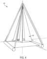
- frame 110 can be shaped approximately as a triangular pyramid.
- the turbine can include six (6) sails.
- Base 120 can include an open frame with a hexagonal hub and 6 spokes.
- a mastless turbine comprises a plurality of sails that rotate about a vertical axis under the influence of wind.
- the turbine also comprises a bottom platform configured to couple the plurality of sails to a first stationary support.
- the bottom platform connects to and is in tension with the plurality of sails at one or more points about the bottom of the plurality of the sails and rotates with the plurality of sails under the influence of wind.
- the turbine further comprises a connector that is configured to couple the plurality of sails to a second stationary support.
- the connector connects to and is in tension with the plurality of sails about the axis of rotation and the top of the plurality of the sails.
- the central connector itself comprises a top portion configured to attach to the second stationary support that during operation of the mastless vertical axis wind turbine does not rotate.
- the central connector also comprises a bottom portion configured to attach to the plurality of the sails that during operation of the mastless vertical axis wind turbine rotates with respect to the top portion with the plurality of sails under the influence of wind.
- a wind turbine rotates about a vertical axis to generate energy under the influence of wind.
- the vanes or sails of the turbine are placed under tension by attaching the bottom of each vane to a platform and the top of each vane to a structure or top tension point positioned about the center of the axis of rotation.
- the top tension point can comprise an external structure that is supported around the turbine, or may comprise a top attachment point. The latter is advantageous where, e.g., the turbine is reversibly installed at various locations where an external support cannot be placed about the turbine. In either case, as a result, the need for a central mast is obviated.
- the vanes In operation, the vanes converge toward the top of the turbine, i.e., where each vane connects to the central structure or tension point at their top edge.
- the configuration of the vanes can be changed by adjusting the position at which the vanes attach to the platform at their bottom edge and the central top tension point.
- a turbine can be part of a turbine array and used in conjunction with an energy storage unit.
- an energy storage unit can be utilized in conjunction with one or more turbines in the array and used to efficiently distribute energy to local or remote locations.
- the energy storage unit can be utilized in conjunction with the one or more turbines to produce a constant or near constant energy output over time and under varying conditions. That is, during operation, all or a portion of the energy generated by the one or more turbines can be distributed to the energy storage unit. During periods of low wind speed, and likewise, low turbine power output, the energy storage unit can be used to increase overall energy output to compensate for a decrease in turbine energy output. During periods of high wind speed, and likewise, high turbine power output, the energy storage unit can be used to provide no or minimal energy output to maintain overall energy output at a constant or near constant level.
- a mastless vertical axis wind turbine that comprises a plurality of sails that rotate about a vertical axis under the influence of wind.
- a platform is connected to and in tension with the plurality of sails at one or more points about the bottom of the plurality of the sails.
- an external frame is connected to and in tension with the plurality of sails at one or more points about the top of the plurality of the sails.
- the external frame itself comprises a plurality of legs that converge above the plurality of sails at a central point about the vertical axis of rotation and extend beyond the path swept by the plurality of sails.
- a coupling mechanism connects one or more of the plurality of legs to the plurality of sails and is configured allow the plurality of sails to rotate about the vertical axis of rotation while the plurality of legs remain stationary.
- a generator in communication with the platform that generates energy in response to rotation of the platform.
- the generator is centrally aligned with the vertical axis of rotation and can be in communication with one or more energy storage units.
- a controller can operate to cause the energy storage units to increase energy output in response to a decrease in generator energy output and decrease energy output in response to an increase in generator energy output.
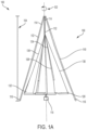
- FIGURE 1A illustrates an embodiment of turbine 100
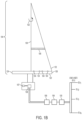
- FIGURE 1B illustrates a cross section of a first portion of turbine 100 illustrated in FIGURE 1A
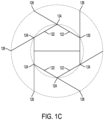
- FIGURE 1C illustrates a platform or second portion of turbine 100 illustrated in FIGURE 1A
- Turbine 100 can be used to generate energy (e.g., mechanical and/or electrical) from air flow.
- turbine 100 can be positioned in an area and subject to air flow (e.g., high wind speed and low wind speed).
- Turbine 100 includes frame 110, rotating platform or base 120, and a plurality of vanes or sails 130.
- frame 110 is an external frame (e.g., external to sails 130) and operates to support and place tension on sails 130 in an upward direction.
- tension may be placed on sails 130 by attaching each to a central point of tension that does not further comprise an external frame.
- sails 130 can connect to a central hook or the like where the hook is free to rotate at one end while it is held stationary at another end. This may be effectuate through the use of bearings or the like, and is advantageous where turbine 100 is installed in compact locations where an external frame would not fit.
- Frame 110 can include any appropriate material to provide the appropriate strength to turbine 100.
- Frame 110 can at least partially support sails 130 and/or base 120, and can be self-erecting and/or manually erected (e.g., by a person).
- frame 110 includes at least three legs 112.
- Legs 112 each have top end 114 and opposing bottom end 116 and 112 can be positioned such that top ends 114 are disposed proximate each other while bottom ends 116 are spaced from one another about the circumference of the circle swept out by sails 130 and/or base 120. Therefore, the ends of legs 112 are uncoupled at or about a bottom portion of frame 110, and coupled (e.g., directly or indirectly) at or about a top end of frame 110.
- frame 110 can have three legs 112 in a shape arranged as a triangular pyramid, where top end 114 of each leg 112 converges near the axis of rotation of sails 130 while bottom ends 116 of each leg 112 are spaced from one another about the circumference of the circle swept out by sails 130 and/or base 120.
- the ratio of a height of frame 110 to a width of frame 110 can be between approximately from 1-to-1 to 2-to-1, while in a preferred embodiment the ratio of the height of frame 110 to the width of frame 110 is approximately 1.3 to approximately 1.
- frame 110 can be any height, even much greater than that of rotating turbine 100 itself. An example might be to increase the ground clearance of turbine 100 for any number of reasons.
- frame 110 can be selected to allow sails 130 to rotate within frame 110 without contacting legs 112.
- the ratio of the height of frame 110 to the width of frame 110 can be approximately the same as the ratio of the height of sail 130 to the width of sail 130, and the overall height of frame 110 can be larger than the overall height of sail 130.
- Platform or base 120 can include any appropriate material, such as metal, fiber reinforced plastics, and/or wood.
- base 120 can comprise an open frame (e.g., at least approximately 50 % of the footprint of base 120 is open and/or components of base 120 comprise an area of less than approximately 50% of the footprint of base 120).
- Sails 130 can rotate in the presence of a fluid flow (e.g., wind) about a central axis of rotation 102 to generate energy.
- Sails 130 can have a shape that is wider at bottom end 132 than at top end 134 where, e.g., sails 130 can be approximately triangularly-shaped or approximately trapezoidally-shaped.
- exterior side 136 of sails 130 can form an approximately conical shape and/or at least a portion of a conical shape.
- the ratio of a height of a sail 130 to a width of a sail 130 can be approximately 2-to-1. In a preferred embodiment, the ratio of the height of sail 130 to the width of sail 130 can be approximately 1.3 to approximately 1.
- Turbine 100 can include an even or odd number of sails 130, where each may be formed of any appropriate material.
- sails 130 can include a material that allows each sail 130 to collapse, be rolled, and/or otherwise reduced in size for storage, transport, and/or other appropriate reasons (e.g., winds exceeding a predetermined maximum velocity).
- each sail 130 has bottom end 132 and top end 134. At least a portion of bottom end 132 can be coupled to base 120 at attachment points 104. Bottom end 132 can extend along a length of base 120. In some embodiments, the width of sail 130 can be approximately the same as the length of base 120. At least a portion of top end 134 can be coupled directly or indirectly to frame 110 or another top tension point.
- sails 130 can be coupled together and/or coupled to a connector (not shown) that couples to frame 110 (e.g., a top portion of frame 110 where legs 112 are coupled).
- a gap can be disposed between top ends 134 of sails 130 and bottom ends 132 of legs 112. This gap can facilitate rotation of sails 130 and/or connection of sails 130 to frame 110.
- Bottom ends 132 of each sail 130 of turbine 100 can be proximate to bottom ends 116 of legs 112.
- top end 134 of each of sail 130 can be a point, and each pointed end of sails 130 can meet and be coupled (e.g., coupled to allow rotation of sails 130) via a connector.
- the connector can directly couple sails 130 to frame 110.
- sails 130 can extend along the entire height 104 (e.g., distance in the direction of central axis of rotation 102) of turbine 100. Otherwise, sails 130 can extend only partially along height 104 of turbine 100 and a connector can have a length that allows sails 130 to be connected to frame 110.
- Sails 130 also include exterior side 136 and opposing interior side 138, both disposed between bottom end 132 and top end 134. At least a portion of exterior side 136 and/or at least a portion of interior side 138 can be free (e.g., not coupled to other sails, frame 110, and/or the base). By allowing the sides of sails 130 to be at least partially free, dead zones (e.g., areas of zero or negligible fluid flow) can be reduced (e.g., when compared with a sail in which the interior side is coupled to a post).
- the lack of a mast which would serve as an obstruction to the crossflow of air between vanes, is also beneficial because it allows air to flow between vanes, further improving operating efficiency.
- described embodiments from most rigid-vane crossflow wind turbines, which have additional structures external to the rotating turbine to channel airflow from a larger swept area into the smaller turbine. This is done to reduce the already high cost of large-scale rigid-vane crossflow designs. Accordingly, described embodiment avoid cost problems or mechanical/operational problems associated with crossflow vertical-axis wind turbines
- connectors can couple proximate corners of sails 130.
- a connector e.g., a chain linkable to a grommet on a sail
- the connectors can meet at a common point and couple to frame 110.
- other shapes can be utilized as appropriate.
- sails 130 and/or connectors can couple at a common point prior to coupling to frame 110.
- connector(s) can couple with ends of triangularly shaped sails 130 at a common point (e.g., a single connector can couple all sails 130 and/or multiple connectors can be utilized to couple two or more sails together).
- the connector can extend from the common point to frame 110 (e.g., to couple proximate the second end of Legs 112).
- an approximately conical shape e.g., area of rotation of sail 130 and/or including the area disposed between connectors
- portion thereof can be formed.
- Sail 130 can include batten or cross-member 106 to inhibit cupping of sail 130 during rotation. Cupping can increase drag of sail 130 and therefore reduce power generation of a turbine.
- Sail 130 can include an opening (e.g., sleeve, pocket, recess, etc.) to receive a cross-member.
- sail 130 can include one or more sleeves disposed between its interior side and exterior side.
- Cross-member(s) 106 can be disposed (e.g., removable and/or fixedly) in the sleeve(s), can be disposed in turbine 100 parallel to the edge of interior end 138 of sail 130 and/or approximately perpendicular to central axis (e.g., axis of rotation) 102.
- base 120 includes a plurality of spokes 122.
- spokes 122 According to the illustrated embodiment, six (6) of spars or spokes 122 have similar shapes and/or sizes.
- installation of turbine 100 is simplified (e.g., when compared with base members that have different size pieces) since spokes 122 are not required to be individually labeled and/or positioned.
- Each spoke 122 includes interior end 124 and opposing exterior end 126. As illustrated, interior end 124 of each spoke 122 can be coupled to another spoke 122 and the exterior end 126 of each spoke 122 can be free (e.g., not coupled to another spoke 122). Spokes 122 can be coupled together to form an approximately hexagonally-shaped hub 128 with six (6) free ends (e.g., exterior ends) of spokes 122 radially disposed about hub 128.
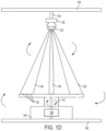
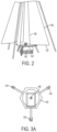
- FIGURE 1D illustrates an embodiment of mastless turbine 100 where an external frame is not utilized. Instead, a central connector is utilized to couple sails 130 to a stationary support, such as support 156. As mentioned, such embodiments are useful where turbine 100 is implemented in locations that are mobile or the like. According to the illustrated embodiment, turbine sails 130 are placed at tension about their top edges by meeting at a central connecting point 150 that is allowed to rotate at its lower end 152, while remaining fixed at its top end 154. This can be effectuated by using a bearing mechanism or the like. Sails 130 attach to connecting point lower end 152, which can comprise a hook, loop, latch, or the like, that reversibly couples to sails 130.
- connecting point lower end 152 rotates with respect to connecting point top end 154, which does not rotate. Further connecting top point 154 attaches to stationary support 156.
- Support 156 can be any component sufficient to support the weight of connecting point 150 and supports same when turbine 100 is placed under tension at connecting point 150.
- support 156 can be a guideline or rail on a watercraft, and the like.
- several of turbines 100 can be placed along the length of support 156 in daisy chain fashion, providing an array of turbines 100.
- platform 142 and stand 140 can be components sufficient to place tension on turbine 100 about the bottom edges of sails 130 while remaining fixed to a bottom stationary support 158.
- generator 108 is housed within stand 140 and rotates therein in response to the rotation of sails 130.
- bottom stationary support 158 can be a fixed component in a watercraft or the like. As one can see, such an embodiment is advantageous because it can be implemented in positions that are themselves mobile or otherwise inaccessible to turbines that require a fixed central mast.
- FIGURE 2 illustrates a perspective view of a portion of turbine 100 implemented on stand 140 and platform 142.
- stand 140 can, in some embodiments, house generator 108 and have mechanism that allow for energy transfer to a remote location such as, e.g., energy storage 109. From there, energy can be transferred to various end users for different applications.
- platform 142 can rotate with sails 130 and can be solid (as illustrated in FIGURE 2 ), or comprise spokes or spires (as illustrated in FIGURE 1C ), where each spoke extends along the length of a bottom edge of a corresponding sail 130.
- a six (6) sail turbine with a hexagonal hub and spoke base can generate power and efficiencies over turbines with a different numbers of sails. This is illustrated where, in FIGURE 1C , there is a corresponding sail 130 extending from each spoke 122.
- Experimental tests reveal that, when airflow across turbine 100 is considered, backwind drag during the upwind portion of an individual sail's cycle is reduced because is falls into the "wind shadow" of the sail ahead of it. At that point, if viewed from the top, the back-winded portion of the cycle is minimal with six (6) sails. There is a point during the cycle where the backwind force equals the forward force and the turbine completely stalls. Accordingly, an optimal function and cost is achieved with six (6) sails. Below that number, the function decreases dramatically. Above that number, the cost increases disproportionately with respect to performance.
- Turbine 100 can be collapsible and/or formed from several uncoupleable components to allow ease of transport and/or storage.
- legs 112 and/or spokes 122 of base 120 can be reversibly coupled to one another for easy assembly and disassembly.
- Sails 130 can be flexible and collapsible (e.g., capable of being rolled or otherwise reduced in size).
- the turbine can then be installed for operation to generate energy.
- Turbine 100 and/or portions thereof can also later be dissembled similarly (e.g., to discontinue operations, to move the turbine, to avoid damage due to high fluid flow, etc.).
- turbine 100 can be utilized in combination with a shelter.
- turbine 100 can include an external frame, sails, and a base.
- Sails 130 can be coupled proximate a first end to base 120 and coupled (e.g., directly or indirectly) to the external frame proximate the second opposing end.
- the external frame can include a first end and a second opposing end. The second opposing end can be disposed proximate the ground.
- Sails 130 and base can be disposed proximate the first end of frame 110.
- the external frame can have a height (e.g., distance between the first end and the second end) that provides a shelter for people, animals, and/or other appropriate people or items (e.g., machinery) beneath sails 130.
- C_harvest is limited by the Betz limit, and typically much lower.
- Horizontal axis turbines typically operate with a C harvest of 0.25 to 0.40.
- Vertical axis turbines have lower C harvest values because a portion of turbine 100 is always driving into the wind, lowering efficiency, creating drag.
- the wind turbine would therefore be one that for a particular purpose is the best overall fit to a list of requirements and constraints, including but not limited to those listed here.
- the power from turbine 100 is extracted from a mechanical linkage to turbine 100's base spar (or spar system), in the form of rotational torque, where Power is expressed as a function of the Torque multiplied by the rate of rotation.
- the rate of rotation of all forms of sails 130 is limited at the outside edge of turbine 100 by the speed of the wind itself. In other words, the tip speed ratio is at or below approximately 1:1 of that of the wind speed.
- Application of a load to turbine 100, to extract power inhibits the rate of rotation.
- Various forms of tuning of power extraction can be employed so that turbine 100's rotational rate is at its most efficient with respect to the wind speed. Overly dragging turbine 100 results in wasted energy due to turbulence, although in many instances this might be tolerable, as tuned power extraction systems add cost.
- a minimum number of sails is generally considered to be two sails, which also might be made as a single sail with a curvature through the middle (with or without gaps for cross flow of working fluid). Non-cross flow variations are less efficient and are therefore of reduced utility.
- the shape of the curve at base 120 is a complex recurve resulting from the oblique
- turbine sails 130 end up with wrinkles and kinks and are less than ideal, both in performance and aesthetics. Furthermore, as the scale of turbine 100 increases, curved battens must be introduced which increase complexity and cost.
- Variations of turbine 100 with more than two sails are envisioned. Among these variations, changes in the curvature of sails 130, including no curvature, are included as potential embodiments. To that end, a variation of turbine 100 with six (6) flat sails can be easily constructed, but any number of sails might be considered. It has been determined that an embodiment with six (6) sails is an attractive configuration, being less costly, easier to construct and transport, etc., than the two (2) sail version.
- base 120 (or spar) consists of several identical components (straight or curved, but straight is shown), which can be attached to create the final spar shape.
- Sails 130 are attached to the spar by various means, including beaded welting, looped fabric over the spar, hold-down lines, etc.
- a perfect hexagonal shape is formed from 6 identical spars, connected to each other at their midpoint. This geometric configuration results in 60 and 30 degree angles, with the spars joined at exactly their midpoints to the end of the succeeding spar.
- These straight components are easy to store and transport (relative to a curved spar), as they can be bundled and fit into a container or bag.
- the spar length to overall diameter can be expressed as the tangent function of 30 degrees times base diameter (0.5773 * D). This is convenient because construction requires little in the way of precise tooling or measuring of angles - all of the angles are a result of lengths of components.
- Base length of sails 130 is nominally from the outermost end of the spar to the midpoint of the spar, but can be more or less as experiments reveal the most economical configuration. More sail material increases costs of materials so must be balanced against energy harvest efficiency. The minimum amount of sail material possible should be employed in turbine 100's construction to minimize cost.
- the flat triangular shape of sails 130 in the multi-sail configuration is easy to fabricate, especially if made as flat sails (having no curvature in the radial direction).
- the letters A, B, and C can be used to designate the bottom inner, bottom outer, and top vertices.
- the three-dimensional coordinates of these vertices can be represented by points (x, y, z), where x and y represent the radial plane and z represents the axial plane, and are expressed in whatever measurements units are desired, (e.g., inches, feet, meters, etc.).
- the rotating torque from turbine 100 can be used to directly or indirectly power electrical generators or alternators, with or without RPM/torque translation, inline (on axis) or off axis from turbine 100, or at various angles to turbine 100's axis of rotation.
- the electricity can be utilized in any way that electricity might be utilized to drive secondary electrical devices of all forms.
- the rotating torque from turbine 100 can be used to directly or indirectly power rotating equipment not utilizing electrical means, including: pumps (water, air, or hydraulic) to drive fluid from one location to another, linear equipment (rotational to linear translation), crankshafts, and the like.
- use of embodiments described herein include uses in dedicated systems, such as: (1) Manufacture of Hydrogen Gas by means of electrolysis of Water (H 2 O); (2) Charging of battery systems or connection to battery-based of fuel-cell based systems for localized energy storage; (3) Manufacture of other chemicals (e.g., methane, ammonia); and (4) Direct or electrically operated pumping systems for water purification, desalination, or sewage treatment.
- a 1-meter (base diameter turbine) operating at an NCF of 0.2, can produce 50-100 gallons of desalinated potable water per day, enough to meet the survival needs of 50-100 people.
- a 3-meter turbine easily set up by one or two persons, will process 9 times as much, enough for over 450 people.
- Turbine 100 can also be used in a system to refit to water wells employing traditional "farm windmills.” This can be accomplished with a mechanical adaptor to the well's existing down-hole apparatus. The resulting system is less costly and eliminates the climbing hazards associated with the older design.
- the conical turbine does not need to be directly over the well, as the mechanical power can be transmitted by means of shafts, belts, endless rope drives, etc.
- Auxiliary power for a boat Direct mechanical operation of pumping apparatus on a boat, Bilge & other pumps, Water makers, Power for propulsion of a boat or water craft, Direct linkage to propeller or other thrust-creating system , and Indirect by means of electrical systems (batteries, fuel cells, etc.) to drive electrically driven propulsion devices.
- one or more turbines might be employed on a vessel for this purpose, with permanent or non-permanent mast structures from which to support turbine 100
- sails 130 are not supported from the bottom or internally by a central shaft, but from above and below. Any support structure within reason can be used to support turbine 100, provided that it is tall enough for sails 130 to be fully deployed and for other practical matters pertaining to turbine operation, and has sufficient structural integrity to allow turbine 100's sails to be properly tensioned for operation via the halyard.
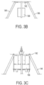
- Embodiments can be utilized in conjunction with a form of self-erecting tripod and a double A-frame that are both suitable for rapid deployment of the conical sail turbine (as well as other applications). These structures can be quickly raised from a basically flat position on the ground to fully erect by means of a single halyard attached to at or near the top of one member and run through a block or compound block set on the other member.
- This structure would be suitable for use on a boat (such as a catamaran) powered by a conical sail system, as it would enable the entire rig to be lowered to deck level when desired or necessary, such as when trailering (ground transport), passing under a low-clearance obstacle, reducing windage or visibility (low detectability) when operating under powered mode.
- a boat such as a catamaran powered by a conical sail system
- the ability to raise and lower such a structure would be desirable as a one-person installation feature or when an approaching storm (such as a tropical cyclone) approaches.
- Another tripod raising method involves connecting all three legs at the vertex, with opposite legs, which form an A-frame, fixed the ground at their bases such that they can freely pivot upwards into deployed position.
- the third leg is connected to the other two at the vertex between them, and a large pin or other through-fastener holds the vertex together so that the members can be moved into upright position.
- base 120 of third member can be pushed or pulled (e.g., by a winch tethered to the A-frame bases) which causes the vertex to rise into position.
- base 120 of the third member is securely anchored so that it will not move laterally on the ground.
- Base 120 of the third leg is attached to a winch or other mechanism in the direction of the center between the bases of the A-frame legs, in order to control the descent.
- Base 120 of the third leg is pulled away from the winch while the winch is let out to control the process and prevent the structure from suddenly collapsing. This process is followed until the vertex is close enough to the ground to be supported by a smaller temporary support (or person) and then lowered the remaining distance at the center (the forces on base 120 become too strong as the vertex opening angle approaches 180 degrees).
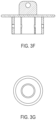
- legs 112 can be constructed of sections of pipe, necked down at the upper ends so that they can be inserted into the preceding sections, and secured with locking pins.
- Turbine 100's base spar can be encircled with a hoop to reduce the possibility of collision of a person or animal moving into the spar's rotational zone.
- Sensors or trips can be used to determine if an object (typically person or animal) encroaches into turbine 100's safety zone and engage to halt or slow the rotation of turbine 100.
- Turbine 100 spars can be positioned high enough so as to be out of the way of normal interactions with humans or animals expected to be in the area (e.g., 7-8 feet above ground).
- Various means can be employed to automatically trigger release of the halyard in the event of high winds or halyard loads in excess of a predetermined value.
- Such devices can be purely mechanical, electromechanical, automatic, or remotely controlled.
- a trip mechanism can be used to simply release the halyard based on tension loading to the halyard itself.
- the halyard might be raised and lowered by a winch mechanism, which might be either hand-cranked or driven by electrical or hydraulic means.
- the winch might be either manually or autonomously actuated by either on-location control systems or from a remote control point.
- Ice buildup on turbine 100's sails can be anticipated under certain weather conditions. Modest ice buildup on turbine 100's sails will have little effect on operation. Moreover, the flexible nature of sails 130 will naturally provide some movement (flexion) that will tend to break ice sheets into fragments and cause the ice to shed without intervention. Due to the relatively slow rotation of turbine 100, horizontal shedding or slinging of ice over significant distances is not a hazard. Ice shedding will tend to be downwards from sails 130. In the event that drifting or shedding of ice builds up to base 120 of the spars, the worst consequence is that turbine 100 won't turn until the ice or snow obstruction is relieved. Base 120 level of turbine 100 can be engineered to account for seasonal snow depths to minimize the potential for snow-related turbine stoppages.
- Hailstones are a hazard to many wind turbines, as they can cause pitting of metal blades or create cracks in fiberglass or composite blades.
- the hail which is falling vertically, can impact the upward-moving blade tips at relative velocities in excess of 400 mph.
- sail 130 turbines shape and materials render it virtually immune to the effects of hail.
- the high vertical angle of sails 130 is nearly parallel to the path of the falling hailstones, which impact sails 130 at a very high (glancing) angle.
- the flexibility of sail 130 material itself yields slightly upon impact and recovers; indeed, the same fabrics used for sails 130 are commonly used at auto dealerships in dedicated hail protection coverings or awnings.
Landscapes
- Engineering & Computer Science (AREA)
- Life Sciences & Earth Sciences (AREA)
- Sustainable Development (AREA)
- Sustainable Energy (AREA)
- Chemical & Material Sciences (AREA)
- Combustion & Propulsion (AREA)
- Mechanical Engineering (AREA)
- General Engineering & Computer Science (AREA)
- Power Engineering (AREA)
- Wind Motors (AREA)
Claims (15)
- Mastlose Windkraftanlage (100) mit vertikaler Achse, wobei die mastlose Windkraftanlage (100) mit vertikaler Achse umfasst:eine Mehrzahl von Flügeln (130), welche sich unter dem Einfluss von Wind um eine vertikale Achse herum drehen;eine untere Plattform (120, 142), welche dazu eingerichtet ist, die Mehrzahl von Flügeln (130) mit einer ersten stationären Halterung (158) zu koppeln, welche während eines Betriebs der mastlosen Windkraftanlage (100) mit vertikaler Achse um das untere Ende der Mehrzahl von Flügeln herum an einem oder mehreren Punkten mit der Mehrzahl von Flügeln (130) verbunden ist und unter Spannung dazu steht und sich unter dem Einfluss von Wind mit der Mehrzahl von Flügeln (130) dreht;ein zentrales Verbindungselement (150), welches dazu eingerichtet ist, die Mehrzahl von Flügeln (130) mit einer zweiten stationären Halterung (156) zu koppeln, welche während eines Betriebs der mastlosen Windkraftanlage (100) mit vertikaler Achse um die Drehachse und das obere Ende der Mehrzahl von Flügeln herum mit der Mehrzahl von Flügeln (130) verbunden ist und unter Spannung dazu steht, wobei das zentrale Verbindungselement (150) umfasst:einen oberen Abschnitt (154), welcher dazu eingerichtet ist, an der zweiten stationären Halterung (156) angebracht zu sein, und welcher sich während eines Betriebs der mastlosen Windkraftanlage (100) mit vertikaler Achse nicht dreht, undeinen unteren Abschnitt (152), welcher dazu eingerichtet ist, an der Mehrzahl von Flügeln (130) angebracht zu sein, und welcher sich während eines Betriebs der mastlosen Windkraftanlage (100) mit vertikaler Achse unter dem Einfluss von Wind in Bezug auf den oberen Abschnitt (154) mit der Mehrzahl von Flügeln (130) dreht,dadurch gekennzeichnet, dass jeder der Mehrzahl von Flügeln (130) entlang der vertikalen Achse an einem gemeinsamen Punkt an dem unteren Abschnitt (152) angebracht ist.
- Mastlose Windkraftanlage (100) mit vertikaler Achse nach Anspruch 1, wobei die untere Plattform (120, 142) eine Mehrzahl von Speichen (122) umfasst, wobei jede der Mehrzahl von Speichen (122) einem Flügel der Mehrzahl von Flügeln (130) entspricht und sich jede Speiche (122) entlang der Länge des unteren Endes eines Flügels der Mehrzahl von Flügeln (130) erstreckt.
- Mastlose Windkraftanlage (100) mit vertikaler Achse nach Anspruch 2, wobei die Mehrzahl von Speichen (122) sechs Speichen (122) in einer hexagonalen Konfiguration umfasst und sich jede Speiche (122) entlang der Länge des unteren Endes eines Flügels der Mehrzahl von Flügeln (130) erstreckt.
- Mastlose Windkraftanlage (100) mit vertikaler Achse nach Anspruch 1, wobei die Mehrzahl von Flügeln (130), wenn sie an dem unteren Abschnitt (152) angebracht ist, eine annähernd konische Form bildet.
- Mastlose Windkraftanlage (100) mit vertikaler Achse nach Anspruch 1, ferner umfassend:
einen Generator (108), welcher in Kommunikation mit der unteren Plattform (120, 142) steht und welcher dazu eingerichtet ist, in Reaktion auf eine Drehung der unteren Plattform (120, 142) Energie zu erzeugen. - Mastlose Windkraftanlage (100) mit vertikaler Achse nach Anspruch 5, ferner umfassend eine oder mehrere Energiespeichereinheiten, welche in Kommunikation mit dem Generator (108) stehen.
- Verfahren zum Erzeugen von Energie unter Verwendung einer mastlosen Windkraftanlage (100) mit vertikaler Achse, wobei das Verfahren umfasst:in Eingriff bringen der mastlosen Windkraftanlage (100) mit vertikaler Achse mit einer ersten stationären Halterung (158) und einer zweiten stationären Halterung (156), wobei die mastlose Windkraftanlage (100) mit vertikaler Achse umfasst:eine Mehrzahl von Flügeln (130), welche sich unter dem Einfluss von Wind um eine vertikale Achse herum drehen;eine untere Plattform (120, 142), welche dazu eingerichtet ist, die Mehrzahl von Flügeln (130) mit der ersten stationären Halterung (158) zu koppeln, welche während eines Betriebs der mastlosen Windkraftanlage (100) mit vertikaler Achse um das untere Ende der Mehrzahl von Flügeln herum an einem oder mehreren Punkten mit der Mehrzahl von Flügeln (130) verbunden ist und unter Spannung dazu steht und sich unter dem Einfluss von Wind mit der Mehrzahl von Flügeln (130) dreht;ein zentrales Verbindungselement, welches dazu eingerichtet ist, die Mehrzahl von Flügeln (130) mit der zweiten stationären Halterung (156) zu koppeln, welche während eines Betriebs der mastlosen Windkraftanlage (100) mit vertikaler Achse um die Drehachse und das obere Ende der Mehrzahl von Flügeln herum mit der Mehrzahl von Flügeln (130) verbunden ist und unter Spannung dazu steht, wobei das zentrale Verbindungselement (150) umfasst:einen oberen Abschnitt (154), welcher dazu eingerichtet ist, an der zweiten stationären Halterung (156) angebracht zu sein, und welcher sich während eines Betriebs der mastlosen Windkraftanlage (100) mit vertikaler Achse nicht dreht, undeinen unteren Abschnitt (152), welcher dazu eingerichtet ist, an der Mehrzahl von Flügeln (130) angebracht zu sein, und welcher sich während eines Betriebs der mastlosen Windkraftanlage (100) mit vertikaler Achse unter dem Einfluss von Wind in Bezug auf den oberen Abschnitt (154) mit der Mehrzahl von Flügeln (130) dreht,dadurch gekennzeichnet, dass jeder der Mehrzahl von Flügeln (130) entlang der vertikalen Achse an einem gemeinsamen Punkt an dem unteren Abschnitt (152) angebracht ist.
- Verfahren nach Anspruch 7, wobei die untere Plattform (120, 142) eine Mehrzahl von Speichen (122) umfasst, wobei jede der Mehrzahl von Speichen (122) einem Flügel der Mehrzahl von Flügeln (130) entspricht und sich jede Speiche (122) entlang der Länge des unteren Endes eines Flügels der Mehrzahl von Flügeln (130) erstreckt.
- Verfahren nach Anspruch 8, wobei die Mehrzahl von Speichen (122) sechs Speichen (122) in einer hexagonalen Konfiguration umfasst und sich jede Speiche (122) entlang der Länge des unteren Endes eines Flügels der Mehrzahl von Flügeln (130) erstreckt.
- Verfahren nach Anspruch 7, wobei die mastlose Windkraftanlage (100) mit vertikaler Achse einen Generator (108) umfasst, welcher in Kommunikation mit der unteren Plattform (120, 142) steht und welcher in Reaktion auf eine Drehung der unteren Plattform (120, 142) Energie erzeugt.
- Verfahren nach Anspruch 10, wobei der Generator (108) mittig zu der vertikalen Drehachse ausgerichtet ist
- Verfahren nach Anspruch 11, wobei die mastlose Windkraftanlage (100) mit vertikaler Achse ferner eine oder mehrere Energiespeichereinheiten umfasst, welche in Kommunikation mit dem Generator (108) stehen.
- Mastlose Windkraftanlage (100) mit vertikaler Achse, wobei die mastlose Windkraftanlage (100) mit vertikaler Achse umfasst:eine Mehrzahl von Flügeln (130), welche sich unter dem Einfluss von Wind um eine vertikale Drehachse herum drehen;eine Plattform (120, 142), welche während eines Betriebs der mastlosen Windkraftanlage (100) mit vertikaler Achse um das untere Ende der Mehrzahl von Flügeln (130) herum an einem oder mehreren Punkten mit der Mehrzahl von Flügeln (130) verbunden ist und unter Spannung dazu steht; undeinen äußeren Rahmen (110), welcher während eines Betriebs der mastlosen Windkraftanlage (100) mit vertikaler Achse um das obere Ende der Mehrzahl von Flügeln (130) herum an einem oder mehreren Punkten mit der Mehrzahl von Flügeln (130) verbunden ist und unter Spannung dazu steht, wobei der äußere Rahmen (110) umfasst:eine Mehrzahl von Schenkeln (112), welche oberhalb der Mehrzahl von Flügeln (130) um die Drehachse herum in einem zentralen Punkt konvergieren und sich über die durch die Mehrzahl von Flügeln (130) gewischte Bahn hinaus erstrecken; undeinen Kopplungsmechanismus, welcher während eines Betriebs der mastlosen Windkraftanlage (100) mit vertikaler Achse einen oder mehrere der Mehrzahl von Schenkeln (112) mit der Mehrzahl von Flügeln (130) verbindet, wobei der Kopplungsmechanismus ermöglicht, dass sich die Mehrzahl von Flügeln (130) um die vertikale Drehachse dreht, während die Mehrzahl von Schenkeln (112) stationär bleibt, und wobei jeder der Mehrzahl von Flügeln (130) entlang der vertikalen Drehachse an einem gemeinsamen Punkt mit dem Kopplungsmechanismus gekoppelt ist.
- Mastlose Windkraftanlage (100) mit vertikaler Achse nach Anspruch 13, ferner umfassend:
einen Generator (108), welcher in Kommunikation mit der Plattform (120, 142) steht und welcher in Reaktion auf eine Drehung der Plattform (120, 142) Energie erzeugt. - Mastlose Windkraftanlage (100) mit vertikaler Achse nach Anspruch 14, wobei der Generator (108) mittig zu der vertikalen Drehachse ausgerichtet ist, wobei die mastlose Windkraftanlage (100) mit vertikaler Achse ferner eine oder mehrere Energiespeichereinheiten umfasst, welche in Kommunikation mit dem Generator (108) stehen.
Applications Claiming Priority (2)
| Application Number | Priority Date | Filing Date | Title |
|---|---|---|---|
| US15/368,303 US9995275B1 (en) | 2015-10-05 | 2016-12-02 | Mastless wind turbine for power generation |
| PCT/US2017/063987 WO2018102568A1 (en) | 2016-12-02 | 2017-11-30 | Mastless wind turbine for power generation |
Publications (4)
| Publication Number | Publication Date |
|---|---|
| EP3548734A1 EP3548734A1 (de) | 2019-10-09 |
| EP3548734A4 EP3548734A4 (de) | 2020-09-16 |
| EP3548734C0 EP3548734C0 (de) | 2025-01-08 |
| EP3548734B1 true EP3548734B1 (de) | 2025-01-08 |
Family
ID=62240522
Family Applications (1)
| Application Number | Title | Priority Date | Filing Date |
|---|---|---|---|
| EP17876489.0A Active EP3548734B1 (de) | 2016-12-02 | 2017-11-30 | Mastlose windturbine zur stromerzeugung |
Country Status (5)
| Country | Link |
|---|---|
| US (5) | US9995275B1 (de) |
| EP (1) | EP3548734B1 (de) |
| CA (1) | CA3045645A1 (de) |
| MX (1) | MX2019006359A (de) |
| WO (1) | WO2018102568A1 (de) |
Families Citing this family (5)
| Publication number | Priority date | Publication date | Assignee | Title |
|---|---|---|---|---|
| TWI714161B (zh) * | 2019-07-10 | 2020-12-21 | 徐子圭 | 船舶動力裝置 |
| CN110374815B (zh) * | 2019-07-29 | 2020-05-05 | 王伟盛 | 一种方便安装且具有防护装置的风力发电装置 |
| US11549485B1 (en) * | 2021-05-04 | 2023-01-10 | Clay Plemmons | Windmill |
| US12098701B2 (en) * | 2021-12-09 | 2024-09-24 | Erik K. Carlsen | Wind turbine with extendable and retractable airfoils |
| US12305616B1 (en) * | 2024-02-23 | 2025-05-20 | Wattmakers LLC | Aerogenerator system, hybrid energy generating system and system |
Family Cites Families (11)
| Publication number | Priority date | Publication date | Assignee | Title |
|---|---|---|---|---|
| US4708592A (en) | 1985-04-15 | 1987-11-24 | Wind Production Company | Helicoidal structures, useful as wind turbines |
| US20100278629A1 (en) * | 2005-12-29 | 2010-11-04 | Krippene Brett C | Vertical Multi-Phased Wind Turbine System |
| US8427000B2 (en) * | 2009-06-24 | 2013-04-23 | Alex Ignatiev | Dual-mode roadway turbines for energy generation from artificial pulsed vehicle wind and continuous ambient wind |
| WO2011011018A1 (en) * | 2009-07-24 | 2011-01-27 | Ari Green Technology, Llc | Portable cylindrical and conical spiral wind turbine |
| US9051916B2 (en) * | 2010-01-06 | 2015-06-09 | IQ Energy | Portable device for generating electric power |
| CN103109084A (zh) * | 2010-04-29 | 2013-05-15 | 托马斯·帕特里克·布莱森 | 风光互补设备 |
| US20120068465A1 (en) * | 2010-09-17 | 2012-03-22 | Freddy Dawoud | Vertical axis wind turbine generator with sails |
| US20130115086A1 (en) * | 2011-11-04 | 2013-05-09 | Steven C. Hench | Vertical axis wind turbine |
| US20140227094A1 (en) * | 2013-02-08 | 2014-08-14 | Zhong Ai XIA | Sailing windmill, fully responsive vawt |
| FR3006718A1 (fr) * | 2013-06-05 | 2014-12-12 | Novatech Inc | Eolienne a axe vertical |
| US11053919B2 (en) * | 2013-09-03 | 2021-07-06 | Jung Hoon Lee | Vertical axis wind turbine with wind vanes |
-
2016
- 2016-12-02 US US15/368,303 patent/US9995275B1/en active Active
-
2017
- 2017-11-30 WO PCT/US2017/063987 patent/WO2018102568A1/en not_active Ceased
- 2017-11-30 EP EP17876489.0A patent/EP3548734B1/de active Active
- 2017-11-30 MX MX2019006359A patent/MX2019006359A/es unknown
- 2017-11-30 CA CA3045645A patent/CA3045645A1/en active Pending
-
2018
- 2018-02-21 US US15/901,701 patent/US11009004B2/en active Active
-
2021
- 2021-05-14 US US17/321,271 patent/US11668278B2/en active Active
-
2023
- 2023-04-27 US US18/308,475 patent/US11898536B2/en active Active
-
2024
- 2024-01-04 US US18/404,741 patent/US12264648B2/en active Active
Also Published As
| Publication number | Publication date |
|---|---|
| US11898536B2 (en) | 2024-02-13 |
| MX2019006359A (es) | 2019-10-02 |
| WO2018102568A1 (en) | 2018-06-07 |
| CA3045645A1 (en) | 2018-06-07 |
| EP3548734A4 (de) | 2020-09-16 |
| EP3548734A1 (de) | 2019-10-09 |
| US12264648B2 (en) | 2025-04-01 |
| US20180156193A1 (en) | 2018-06-07 |
| US20240133359A1 (en) | 2024-04-25 |
| US11009004B2 (en) | 2021-05-18 |
| EP3548734C0 (de) | 2025-01-08 |
| US20230349357A1 (en) | 2023-11-02 |
| US9995275B1 (en) | 2018-06-12 |
| US11668278B2 (en) | 2023-06-06 |
| US20180180020A1 (en) | 2018-06-28 |
| US20210270234A1 (en) | 2021-09-02 |
Similar Documents
| Publication | Publication Date | Title |
|---|---|---|
| US12264648B2 (en) | Mastless wind turbine for power generation | |
| US12305615B2 (en) | Mastless wind turbine with stationary sails for improved power generation | |
| US8443571B2 (en) | Wind power equipment and assembly | |
| US4708592A (en) | Helicoidal structures, useful as wind turbines | |
| US20250198386A1 (en) | High Capacity, Shallow Draft, Ocean-Borne Wind Turbine | |
| US20110042958A1 (en) | Collapsible vertical-axis turbine | |
| US9347425B2 (en) | Offshore floating barge to support sustainable power generation | |
| EP0045202A1 (de) | Durch Windkraft angetriebene Stromgeneratoren | |
| US20120061968A1 (en) | Burrell compound axial windmill | |
| US20120068465A1 (en) | Vertical axis wind turbine generator with sails | |
| CN101611226A (zh) | 能量提取方法和设备 | |
| US20150233353A1 (en) | Vertical axis wind turbine | |
| JP2014152725A (ja) | 風力発電装置 | |
| US20180320277A1 (en) | Inexpensive Hydrogen from Wind and Water Using Aerostats and Electrolysis | |
| US20220213871A1 (en) | Ducted wind turbine and support platform | |
| KR20240129609A (ko) | 부유식 풍력 터빈 시스템 및 방법 | |
| CN203175763U (zh) | 一种水陆两用风帆式风力发电机 | |
| US11885297B2 (en) | Transitioning wind turbine | |
| KR20240142666A (ko) | 풍력과 수력 융합 발전기 시스템 | |
| SK8944Y1 (sk) | Veterná vírová stena |
Legal Events
| Date | Code | Title | Description |
|---|---|---|---|
| STAA | Information on the status of an ep patent application or granted ep patent |
Free format text: STATUS: THE INTERNATIONAL PUBLICATION HAS BEEN MADE |
|
| PUAI | Public reference made under article 153(3) epc to a published international application that has entered the european phase |
Free format text: ORIGINAL CODE: 0009012 |
|
| STAA | Information on the status of an ep patent application or granted ep patent |
Free format text: STATUS: REQUEST FOR EXAMINATION WAS MADE |
|
| 17P | Request for examination filed |
Effective date: 20190524 |
|
| AK | Designated contracting states |
Kind code of ref document: A1 Designated state(s): AL AT BE BG CH CY CZ DE DK EE ES FI FR GB GR HR HU IE IS IT LI LT LU LV MC MK MT NL NO PL PT RO RS SE SI SK SM TR |
|
| AX | Request for extension of the european patent |
Extension state: BA ME |
|
| DAV | Request for validation of the european patent (deleted) | ||
| DAX | Request for extension of the european patent (deleted) | ||
| A4 | Supplementary search report drawn up and despatched |
Effective date: 20200818 |
|
| RIC1 | Information provided on ipc code assigned before grant |
Ipc: F03D 9/00 20160101ALI20200812BHEP Ipc: F03D 3/00 20060101AFI20200812BHEP Ipc: F03D 9/11 20160101ALI20200812BHEP Ipc: F03D 9/25 20160101ALI20200812BHEP Ipc: F03D 3/06 20060101ALI20200812BHEP |
|
| STAA | Information on the status of an ep patent application or granted ep patent |
Free format text: STATUS: EXAMINATION IS IN PROGRESS |
|
| 17Q | First examination report despatched |
Effective date: 20221201 |
|
| RAP1 | Party data changed (applicant data changed or rights of an application transferred) |
Owner name: J. HENCH CONSULTING, INC. |
|
| RIN1 | Information on inventor provided before grant (corrected) |
Inventor name: J. HENCH CONSULTING, INC. |
|
| GRAP | Despatch of communication of intention to grant a patent |
Free format text: ORIGINAL CODE: EPIDOSNIGR1 |
|
| STAA | Information on the status of an ep patent application or granted ep patent |
Free format text: STATUS: GRANT OF PATENT IS INTENDED |
|
| INTG | Intention to grant announced |
Effective date: 20240809 |
|
| RIN1 | Information on inventor provided before grant (corrected) |
Inventor name: HENCH, STEVEN C.. |
|
| GRAS | Grant fee paid |
Free format text: ORIGINAL CODE: EPIDOSNIGR3 |
|
| GRAA | (expected) grant |
Free format text: ORIGINAL CODE: 0009210 |
|
| STAA | Information on the status of an ep patent application or granted ep patent |
Free format text: STATUS: THE PATENT HAS BEEN GRANTED |
|
| AK | Designated contracting states |
Kind code of ref document: B1 Designated state(s): AL AT BE BG CH CY CZ DE DK EE ES FI FR GB GR HR HU IE IS IT LI LT LU LV MC MK MT NL NO PL PT RO RS SE SI SK SM TR |
|
| REG | Reference to a national code |
Ref country code: GB Ref legal event code: FG4D |
|
| REG | Reference to a national code |
Ref country code: CH Ref legal event code: EP |
|
| REG | Reference to a national code |
Ref country code: DE Ref legal event code: R096 Ref document number: 602017087290 Country of ref document: DE |
|
| REG | Reference to a national code |
Ref country code: IE Ref legal event code: FG4D |
|
| U01 | Request for unitary effect filed |
Effective date: 20250115 |
|
| U07 | Unitary effect registered |
Designated state(s): AT BE BG DE DK EE FI FR IT LT LU LV MT NL PT RO SE SI Effective date: 20250122 |
|
| PG25 | Lapsed in a contracting state [announced via postgrant information from national office to epo] |
Ref country code: RS Free format text: LAPSE BECAUSE OF FAILURE TO SUBMIT A TRANSLATION OF THE DESCRIPTION OR TO PAY THE FEE WITHIN THE PRESCRIBED TIME-LIMIT Effective date: 20250408 |
|
| PG25 | Lapsed in a contracting state [announced via postgrant information from national office to epo] |
Ref country code: PL Free format text: LAPSE BECAUSE OF FAILURE TO SUBMIT A TRANSLATION OF THE DESCRIPTION OR TO PAY THE FEE WITHIN THE PRESCRIBED TIME-LIMIT Effective date: 20250108 |
|
| PG25 | Lapsed in a contracting state [announced via postgrant information from national office to epo] |
Ref country code: ES Free format text: LAPSE BECAUSE OF FAILURE TO SUBMIT A TRANSLATION OF THE DESCRIPTION OR TO PAY THE FEE WITHIN THE PRESCRIBED TIME-LIMIT Effective date: 20250108 |
|
| PG25 | Lapsed in a contracting state [announced via postgrant information from national office to epo] |
Ref country code: IS Free format text: LAPSE BECAUSE OF FAILURE TO SUBMIT A TRANSLATION OF THE DESCRIPTION OR TO PAY THE FEE WITHIN THE PRESCRIBED TIME-LIMIT Effective date: 20250508 Ref country code: NO Free format text: LAPSE BECAUSE OF FAILURE TO SUBMIT A TRANSLATION OF THE DESCRIPTION OR TO PAY THE FEE WITHIN THE PRESCRIBED TIME-LIMIT Effective date: 20250408 |
|
| PG25 | Lapsed in a contracting state [announced via postgrant information from national office to epo] |
Ref country code: HR Free format text: LAPSE BECAUSE OF FAILURE TO SUBMIT A TRANSLATION OF THE DESCRIPTION OR TO PAY THE FEE WITHIN THE PRESCRIBED TIME-LIMIT Effective date: 20250108 |
|
| PG25 | Lapsed in a contracting state [announced via postgrant information from national office to epo] |
Ref country code: GR Free format text: LAPSE BECAUSE OF FAILURE TO SUBMIT A TRANSLATION OF THE DESCRIPTION OR TO PAY THE FEE WITHIN THE PRESCRIBED TIME-LIMIT Effective date: 20250409 |
|
| PG25 | Lapsed in a contracting state [announced via postgrant information from national office to epo] |
Ref country code: SM Free format text: LAPSE BECAUSE OF FAILURE TO SUBMIT A TRANSLATION OF THE DESCRIPTION OR TO PAY THE FEE WITHIN THE PRESCRIBED TIME-LIMIT Effective date: 20250108 |
|
| PG25 | Lapsed in a contracting state [announced via postgrant information from national office to epo] |
Ref country code: CZ Free format text: LAPSE BECAUSE OF FAILURE TO SUBMIT A TRANSLATION OF THE DESCRIPTION OR TO PAY THE FEE WITHIN THE PRESCRIBED TIME-LIMIT Effective date: 20250108 |
|
| PG25 | Lapsed in a contracting state [announced via postgrant information from national office to epo] |
Ref country code: SK Free format text: LAPSE BECAUSE OF FAILURE TO SUBMIT A TRANSLATION OF THE DESCRIPTION OR TO PAY THE FEE WITHIN THE PRESCRIBED TIME-LIMIT Effective date: 20250108 |
|
| PLBE | No opposition filed within time limit |
Free format text: ORIGINAL CODE: 0009261 |
|
| STAA | Information on the status of an ep patent application or granted ep patent |
Free format text: STATUS: NO OPPOSITION FILED WITHIN TIME LIMIT |
|
| 26N | No opposition filed |
Effective date: 20251009 |
|
| U20 | Renewal fee for the european patent with unitary effect paid |
Year of fee payment: 9 Effective date: 20251110 |
|
| PGFP | Annual fee paid to national office [announced via postgrant information from national office to epo] |
Ref country code: GB Payment date: 20251023 Year of fee payment: 9 |