EP3547582B1 - Radio bearer specific cqi reporting - Google Patents
Radio bearer specific cqi reporting Download PDFInfo
- Publication number
- EP3547582B1 EP3547582B1 EP19174468.9A EP19174468A EP3547582B1 EP 3547582 B1 EP3547582 B1 EP 3547582B1 EP 19174468 A EP19174468 A EP 19174468A EP 3547582 B1 EP3547582 B1 EP 3547582B1
- Authority
- EP
- European Patent Office
- Prior art keywords
- channel state
- state feedback
- trigger criteria
- reporting trigger
- radio bearer
- Prior art date
- Legal status (The legal status is an assumption and is not a legal conclusion. Google has not performed a legal analysis and makes no representation as to the accuracy of the status listed.)
- Active
Links
- 238000000034 method Methods 0.000 claims description 45
- 230000011664 signaling Effects 0.000 claims description 13
- 238000012913 prioritisation Methods 0.000 claims description 10
- 238000004891 communication Methods 0.000 claims description 8
- 230000007774 longterm Effects 0.000 claims description 5
- 230000005540 biological transmission Effects 0.000 description 15
- 101150097247 CRT1 gene Proteins 0.000 description 8
- 230000000737 periodic effect Effects 0.000 description 4
- 238000009125 cardiac resynchronization therapy Methods 0.000 description 3
- 238000005516 engineering process Methods 0.000 description 3
- 238000005259 measurement Methods 0.000 description 3
- 238000013468 resource allocation Methods 0.000 description 3
- 230000002860 competitive effect Effects 0.000 description 2
- 230000001419 dependent effect Effects 0.000 description 2
- 238000010586 diagram Methods 0.000 description 2
- 230000000694 effects Effects 0.000 description 2
- 238000001228 spectrum Methods 0.000 description 2
- 230000001960 triggered effect Effects 0.000 description 2
- 230000001413 cellular effect Effects 0.000 description 1
- 230000000052 comparative effect Effects 0.000 description 1
- 238000001514 detection method Methods 0.000 description 1
- 238000012986 modification Methods 0.000 description 1
- 230000004048 modification Effects 0.000 description 1
- 238000012544 monitoring process Methods 0.000 description 1
Images


Classifications
-
- H—ELECTRICITY
- H04—ELECTRIC COMMUNICATION TECHNIQUE
- H04W—WIRELESS COMMUNICATION NETWORKS
- H04W72/00—Local resource management
- H04W72/20—Control channels or signalling for resource management
- H04W72/23—Control channels or signalling for resource management in the downlink direction of a wireless link, i.e. towards a terminal
-
- H—ELECTRICITY
- H04—ELECTRIC COMMUNICATION TECHNIQUE
- H04L—TRANSMISSION OF DIGITAL INFORMATION, e.g. TELEGRAPHIC COMMUNICATION
- H04L5/00—Arrangements affording multiple use of the transmission path
- H04L5/003—Arrangements for allocating sub-channels of the transmission path
- H04L5/0053—Allocation of signaling, i.e. of overhead other than pilot signals
- H04L5/0057—Physical resource allocation for CQI
-
- H—ELECTRICITY
- H04—ELECTRIC COMMUNICATION TECHNIQUE
- H04L—TRANSMISSION OF DIGITAL INFORMATION, e.g. TELEGRAPHIC COMMUNICATION
- H04L1/00—Arrangements for detecting or preventing errors in the information received
- H04L1/0001—Systems modifying transmission characteristics according to link quality, e.g. power backoff
- H04L1/0023—Systems modifying transmission characteristics according to link quality, e.g. power backoff characterised by the signalling
- H04L1/0026—Transmission of channel quality indication
-
- H—ELECTRICITY
- H04—ELECTRIC COMMUNICATION TECHNIQUE
- H04B—TRANSMISSION
- H04B7/00—Radio transmission systems, i.e. using radiation field
- H04B7/02—Diversity systems; Multi-antenna system, i.e. transmission or reception using multiple antennas
- H04B7/04—Diversity systems; Multi-antenna system, i.e. transmission or reception using multiple antennas using two or more spaced independent antennas
- H04B7/06—Diversity systems; Multi-antenna system, i.e. transmission or reception using multiple antennas using two or more spaced independent antennas at the transmitting station
- H04B7/0613—Diversity systems; Multi-antenna system, i.e. transmission or reception using multiple antennas using two or more spaced independent antennas at the transmitting station using simultaneous transmission
- H04B7/0615—Diversity systems; Multi-antenna system, i.e. transmission or reception using multiple antennas using two or more spaced independent antennas at the transmitting station using simultaneous transmission of weighted versions of same signal
- H04B7/0619—Diversity systems; Multi-antenna system, i.e. transmission or reception using multiple antennas using two or more spaced independent antennas at the transmitting station using simultaneous transmission of weighted versions of same signal using feedback from receiving side
- H04B7/0621—Feedback content
- H04B7/0632—Channel quality parameters, e.g. channel quality indicator [CQI]
-
- H—ELECTRICITY
- H04—ELECTRIC COMMUNICATION TECHNIQUE
- H04L—TRANSMISSION OF DIGITAL INFORMATION, e.g. TELEGRAPHIC COMMUNICATION
- H04L1/00—Arrangements for detecting or preventing errors in the information received
- H04L1/0001—Systems modifying transmission characteristics according to link quality, e.g. power backoff
- H04L1/0023—Systems modifying transmission characteristics according to link quality, e.g. power backoff characterised by the signalling
- H04L1/0028—Formatting
-
- H—ELECTRICITY
- H04—ELECTRIC COMMUNICATION TECHNIQUE
- H04L—TRANSMISSION OF DIGITAL INFORMATION, e.g. TELEGRAPHIC COMMUNICATION
- H04L1/00—Arrangements for detecting or preventing errors in the information received
- H04L1/0001—Systems modifying transmission characteristics according to link quality, e.g. power backoff
- H04L1/0023—Systems modifying transmission characteristics according to link quality, e.g. power backoff characterised by the signalling
- H04L1/0027—Scheduling of signalling, e.g. occurrence thereof
-
- H—ELECTRICITY
- H04—ELECTRIC COMMUNICATION TECHNIQUE
- H04L—TRANSMISSION OF DIGITAL INFORMATION, e.g. TELEGRAPHIC COMMUNICATION
- H04L1/00—Arrangements for detecting or preventing errors in the information received
- H04L1/0001—Systems modifying transmission characteristics according to link quality, e.g. power backoff
- H04L1/0023—Systems modifying transmission characteristics according to link quality, e.g. power backoff characterised by the signalling
- H04L1/0028—Formatting
- H04L1/0029—Reduction of the amount of signalling, e.g. retention of useful signalling or differential signalling
-
- H—ELECTRICITY
- H04—ELECTRIC COMMUNICATION TECHNIQUE
- H04L—TRANSMISSION OF DIGITAL INFORMATION, e.g. TELEGRAPHIC COMMUNICATION
- H04L1/00—Arrangements for detecting or preventing errors in the information received
- H04L1/0001—Systems modifying transmission characteristics according to link quality, e.g. power backoff
- H04L1/0023—Systems modifying transmission characteristics according to link quality, e.g. power backoff characterised by the signalling
- H04L1/0028—Formatting
- H04L1/003—Adaptive formatting arrangements particular to signalling, e.g. variable amount of bits
-
- H—ELECTRICITY
- H04—ELECTRIC COMMUNICATION TECHNIQUE
- H04W—WIRELESS COMMUNICATION NETWORKS
- H04W24/00—Supervisory, monitoring or testing arrangements
-
- H—ELECTRICITY
- H04—ELECTRIC COMMUNICATION TECHNIQUE
- H04W—WIRELESS COMMUNICATION NETWORKS
- H04W48/00—Access restriction; Network selection; Access point selection
- H04W48/08—Access restriction or access information delivery, e.g. discovery data delivery
-
- H—ELECTRICITY
- H04—ELECTRIC COMMUNICATION TECHNIQUE
- H04W—WIRELESS COMMUNICATION NETWORKS
- H04W56/00—Synchronisation arrangements
- H04W56/001—Synchronization between nodes
-
- H—ELECTRICITY
- H04—ELECTRIC COMMUNICATION TECHNIQUE
- H04W—WIRELESS COMMUNICATION NETWORKS
- H04W72/00—Local resource management
- H04W72/50—Allocation or scheduling criteria for wireless resources
- H04W72/54—Allocation or scheduling criteria for wireless resources based on quality criteria
- H04W72/542—Allocation or scheduling criteria for wireless resources based on quality criteria using measured or perceived quality
-
- H—ELECTRICITY
- H04—ELECTRIC COMMUNICATION TECHNIQUE
- H04W—WIRELESS COMMUNICATION NETWORKS
- H04W88/00—Devices specially adapted for wireless communication networks, e.g. terminals, base stations or access point devices
- H04W88/02—Terminal devices
Definitions
- the present invention relates generally to channel state feedback provided from a user equipment to a base station, and more specifically to providing channel state feedback adapted to different types of downlink traffic.
- LTE has been set aggressive performance requirements which rely on physical layer technologies, such as e.g. Orthogonal Frequency Division Multiplexing (OFDM) and Multiple-Input Multiple-Output (MIMO) systems to achieve these targets.
- OFDM Orthogonal Frequency Division Multiplexing
- MIMO Multiple-Input Multiple-Output
- Some main objectives of LTE are to minimize the system and User Equipment (UE) complexities, to allow flexible spectrum deployment in existing or new frequency spectrum and to enable co-existence with other 3GPP Radio Access Technologies (RATs).
- UE User Equipment
- the LTE uplink is based on single-carrier modulation and uses frequency and time division multiple access principles (FDMA and TDMA),
- the LTE uplink consists of physical uplink control channels and data channels that are orthogonally frequency multiplexed.
- the single-carrier property of the LTE uplink makes it impossible for a UE to transmit on a physical control channel and a physical data channel in the same transmission-time-interval (TTI).
- TTI transmission-time-interval
- the UE will use the physical control channel to transmit control signaling only in the case when the UE has no data transmission, and hence is not using the physical data channel.
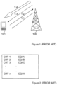
- a conventional downlink scheduling concept can be described with stages 1:1 - 1:4, as illustrated in figure 1 .
- a base station 100 which is referred to as an eNodeB in LTE, communicating with a UE 101, transmits reference signals to UE 101 in a first stage 1:1.
- the reference signals can be used by UE 101 to determine the present downlink channel quality.
- LTE uses feedback from the UE to the eNodeB of the instantaneous channel conditions.
- UE 101 After having determined the downlink channel quality on the basis of the received reference signals, UE 101 therefore sends one or more channel state feedback reports, which in this context typically are referred to as Channel Quality Indication (CQI) reports, back to eNodeB 100 in a second stage 1:2.
- CQI Channel Quality Indication
- the content of the one or more CQI reports can be retrieved and used by a scheduler (not shown).
- the scheduler uses the information retrieved from the CQI reports to perform resource allocation.
- UE 101 is informed of the resource allocation in a next stage 1:3.
- a resource allocation typically results in a transmission of downlink data over the allocated resource, as indicated with a final stage 1:4.
- UEs will be capable of transmitting different types of CQI reports, such as full CQI reports, partial CQI reports, and/or differential CQI reports.
- full CQI reports are defined to cover the whole downlink transmission bandwidth scheduled for a UE, but may have different frequency resolution. This type of CQI reports may be filtered and processed in different ways.
- different full CQI reports may be encoded in different ways. Partial CQI reports on the other hand may be set to cover only a part of a specified downlink transmission bandwidth. The part covered by a partial CQI report may be a set of contiguous, or a set of distributed resource blocks.
- a differential CQI report may contain an encoded version of the update vector relative to a previous CQI report.
- a CQI reporting mechanism which is based on different types of CQI reports, such as e.g. the ones described above, may be introduced by way of, for each CQI report type, defining a set of rules that triggers the transmission of a report of the respective CQI report type from a respective UE.
- Each UE has a configured CQI reporting trigger set (CRTS), wherein the CRTS consists of one or more CQI reporting triggers (CRT), specifying under which criteria a specific type of CQI report shall be transmitted.
- CRTS CQI reporting trigger set
- CRT CQI reporting triggers
- Each CRT is associated with a specific type of CQI report in such a way that when a triggering criteria is fulfilled, the respective UE transmits a CQI report of the associated type to the respective eNodeB.
- a CRT is typically expressed in terms of a logical expression which may involve one of, or a combination of timers, events, and conditions, consisting of logical statements, such as AND, OR, NOT, WHEN, and/or IF.
- a simple periodic CQI reporting trigger may just consist of a periodic timer and a rule that a certain CQI report shall be transmitted every time the timer expires.
- a simple event based CQI reporting trigger may state that a certain type of CQI report shall be transmitted every time the triggering event, such as e.g. a handover event, occurs.
- a condition that could be included in the decision to transmit a certain CQI report or not, is e.g. if the downlink activity is above a specified threshold.
- the eNodeB may also have the option to explicitly request for CQI reports on demand, typically by using RRC signaling.
- FIG. 2 illustrates a table of a CQI trigger configuration of a UE, as described above.
- the table comprises a plurality of CQI reporting triggers, CRT 1-n, configured for the UE.
- Each CRT is associated with one CQI report type, CQI A-X.
- CQI A-X When for example the trigger criteria specified by CRT 1 is true, a report type, defined by CQI A will be transmitted from the UE to an eNodeB, as indicated in the table. What types of CQI reports a UE shall use, and what criteria that will trigger them, are typically set-up by higher layer, RRC signaling.
- CQI reports may occur at known time instances and may use a format known to the eNodeB, or the occurrence and format may be more dynamic. In the latter case the MAC header typically needs to include information about how the CQI report was transmitted, or else the eNodeB may have to perform blind detection on the CQI transmission format.
- a CQI report may include information, such as e.g. pre-coding weights or other feedback parameters, to be used by the eNodeB multiple antenna transmission scheme.
- the amount of resources needed to be reserved for a certain UE will also depend on the MIMO scheme configured for that UE, potentially adding further complication to the configuration of the reserved resources.
- the amount of bits that can be spent on CQI reporting may depend on a number of different criteria, such as: downlink transmission mode, e.g. SISO or MIMO; type of downlink traffic, e.g. VoIP or Web; downlink radio characteristics, e.g. coherence time and/or coherence bandwidth; current uplink load and/or current downlink activity.
- downlink transmission mode e.g. SISO or MIMO
- type of downlink traffic e.g. VoIP or Web
- downlink radio characteristics e.g. coherence time and/or coherence bandwidth
- current uplink load and/or current downlink activity e.g. current downlink activity.
- CQI reports can be transmitted in two ways.
- a CQI report can be transmitted on a dedicated control channel resource when no data is transmitted simultaneously, or on a scheduled resource on a shared channel when uplink data and control signaling is transmitted simultaneously.
- a drawback with such a scheme is that resources must be reserved for control signaling; resources that will be unused when the UE is transmitting data simultaneously with control signaling. This further adds to the importance of keeping the CQI reporting overhead at a minimum.
- GBR Guaranteed Bit Rate
- WO O3/023995 A1 describes a closed-loop signalling method controlling multiple transmit beams.
- the method comprises transmitting a plurality of beams from a first transceiver via a plurality of transmission channels to a second transceiver.
- characteristics of the plurality of transmitted beams received at the second transceiver are evaluated.
- the method also includes deriving, at the second transceiver, beamforming information for being fed back from the second transceiver to the first transceiver based on the evaluated characteristics.
- the beamforming information is usable for controlling, at the first transceiver, the transmitting of the plurality of beams.
- the method also comprises selecting, at the second transceiver, at least one set of beamforming information for being fed back from the second transceiver via a feedback path to the first transceiver.
- the method also comprises calculating, at the first transceiver, additional beamforming information which was not contained in the feedback path, based on the beamforming information being fed back.
- US 7,003,290 B1 describes at least two different triggers for sending a measurement report from the mobile station to the network.
- the network specifies the triggers to be used in different measurement report types.
- the triggers are preferably upper or lower threshold values for parameters of the radio signal.
- the mobile station sends the network a measurement report.
- US 2003/123396 A1 addresse reporting downlink channel quality in a high-speed packet communication system.
- a channel analyzer measures downlink channel quality from a received reference channel signal.
- a controller determines whether a current TTI (Transmission Time Interval) is a TTI corresponding to a multiple of a first TTI or a TTI corresponding to a multiple of a second TTI.
- TTI Transmission Time Interval
- the controller determines CQ (Channel Quality) refreshment information for a downlink channel received from the Node B based on the measured downlink channel quality, and if the current TTI is a TTI corresponding to a multiple of the second TTI, the controller determines CQ refinement information for the downlink channel based on the measured downlink channel quality.
- a CQ information transmitter generates CQ refreshment information or CQ refinement information under the control of the controller, and transmits the generated CQ refreshment information or CQ refinement information over an uplink.
- the present invention aims to solve at least one problem addressed above by providing a more efficient use of the signalling resources when delivering channel state feedback information from a User Equipment (UE) to an base station.
- UE User Equipment
- One example relates to a method for providing channel state feedback from a UE to a base station.
- the method comprises the step of determining whether at least one channel state feedback reporting trigger criteria is valid or not, wherein each one or more channel state feedback reporting trigger is applied to one or more specific radio bearers.
- a channel state feedback report of a specified type is generated if at least one channel state feedback reporting trigger criteria is found to be valid, and the generated channel state feedback report is transmitted to the base station.
- the UE decides if a channel state feedback report is to be transmitted by checking for every trigger criteria that has been met that the respective trigger also is applied to at least one radio bearer.
- two or more different types of channel state feedback reports are applied for the UE.
- a separate set of radio bearer specific channel state feedback reporting trigger criteria is applied for each channel state feedback report type.
- the determining step may be repeated for each set of channel state feedback reporting trigger criteria, and every match is registered. On the basis of the registered one or more matches, one or more channel state feedback reports are generated and transmitted when all channel state feedback reporting trigger criteria specified for the UE has been checked.
- one or more channel state feedback reports are generated and transmitted on the basis of a prioritization rule, specifying how to prioritize between different channel state feedback report types and/or subsets of channel state feedback report types.
- the generated reports are then transmitted to the UE.
- a base station comprising a scheduler for providing configured channel state feedback reporting trigger criteria to a UE.
- radio bearer specific channel state feedback reporting trigger criteria is generated for the UE.
- each channel state feedback reporting trigger is applied to one or more specific radio bearers.
- the generating step is repeated for each channel state feedback report type to be applied to the UE, thereby providing a radio bearer specific channel state feedback configuration to the UE.
- the channel state feedback reporting trigger criteria configuration is transmitted to the UE.
- the generating step comprises rules, specifying how to prioritize between different types of channel state feedback reports and/or different subsets of channel state feedback report types when channel state feedback reporting trigger criteria for more than one type has been found to valid for the UE.
- the radio bearer specific channel state feedback reporting trigger criteria may be transmitted to the UE through higher layer signaling.
- such a procedure may be based on the relation between downlink and uplink data of said UE.
- a user equipment to be operating in a communication network is adapted to provide radio bearer specific channel state feedback to a base station.
- the UE comprises a determining unit for determining whether at least one channel state feedback reporting trigger criteria, wherein each channel state feedback reporting trigger is applied to one or more radio bearers, configured for the UE is valid or not.
- the UE also comprises a generating unit, for generating a channel state feedback report of a specific type if at least one channel state feedback reporting trigger criteria is found to be valid.
- a transmitting unit of the UE is then used for transmitting a generated channel state feedback report to the base station.
- two or more different types of channel state feedback reports are applied for the UE.
- a separate set of channel state feedback reporting trigger criteria is applied for the UE for each channel state feedback report type.
- the determining unit may be adapted to execute the described determination for each set of radio bearer specific channel state feedback reporting trigger criteria, and the generating unit may be adapted to generate at least one channel state feedback report once all channel state feedback reporting trigger criteria specified for the UE has been checked.
- the generating unit may also comprise a storing unit for storing an indication of each report type for which an associated channel state feedback reporting trigger criteria has been found to be valid in said determining step.
- the generating unit may be adapted to base its selection of report type on a prioritization between different channel state feedback report types and/or subsets of channel state feedback report types.
- a base station for providing configured channel state feedback reporting trigger criteria to a UE.
- the base station which typically is an eNodeB, comprises a generating unit for generating channel state feedback reporting trigger criteria for the UE, wherein each channel state feedback reporting trigger is defined so that it is applied to one or more radio bearers.
- the base station also comprises a transmitting unit for transmitting configured radio bearer specific channel state feedback reporting trigger criteria to the UE.
- the configured channel state feedback reporting trigger criteria is typically transmitted to the UE through higher layer signaling.
- the generating unit is adapted to generate different channel state feedback reporting trigger criteria that is applied to one or more radio bearers in order to obtain a channel state feedback reporting process which is adapted to different types of downlink traffic.
- this generating process may be based on the relation between downlink and uplink data of said UE.
- the present invention involves a method, a base station and a UE which takes into consideration that different types of downlink traffic have different demands when reporting channel state feedback information. More specifically, the present invention refers to a mechanism for applying each CQI reporting trigger, configured for a UE, to one or more specific radio bearers, each of which supports the respective CQI reporting trigger criteria. By introducing such a mechanism, a UE will be able to determine if a CQI report is to be transmitted by checking for every CQI reporting trigger if it is valid And applied to at least one of the radio bearers, supporting the respective CQI reporting trigger criteria.
- channel state feedback reports delivered from a UE will consequently be referred to as CQI reports, while base stations which participates in the channel state feedback reporting consequently will be referred to as eNodeBs.
- CQI channel state reporting trigger criteria the rules configured for a UE, specifying under which conditions a CQI report is to be generated and transmitted. It is, however, to be understood that the described example may be applicable also for other, comparable channel state feedback implementations, involving other comparable entities.
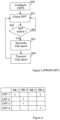
- Figure 3 is a simplified flow chart illustrating a method for providing channel state feedback in the form of CQI reports from a UE to an eNodeB, according to the prior art.
- the criteria for when and how to deliver different types of CQI reports is configured as a CRTS by eNodeB, and delivered to the UE in a first step 300.
- a continuous checking procedure for determining if any CRT criteria, specified by a CRTS is valid, is initiated.
- a CQI report of a respective type will be generated at the UE at a step 303, and transmitted to the eNodeB, as illustrated with a final step 304. If, however, no CRT criteria is found to be, the checking procedure is repeated, starting at step 301. If there are a plurality of alternative types of CQI reports configured for the UE, the described checking procedure will be repeated for each report type.
- Figure 4 is a table illustrating how a number of radio bearer specific CQI reporting triggers may be configured in order to provide a more efficient CQI reporting mechanism which is adapted to take into consideration that different types of services may have different CQI reporting requirements.
- the table of figure 4 shows four different CQI reporting triggers, referred to as CRT 1-4, and four different radio bearers, RB 1-4. Each CQI reporting trigger is applied to one or more radio bearers.
- CRT 1 is applied to the two radio bearers, RB 1 and RB 4.
- CRT 2 and 3 are both applied to RB 2, while CRT 4 is applied to RB 4.
- the UE determines if a CQI report is to be transmitted to an eNodeB by checking the trigger criteria defined by each CRT, and if any of the trigger criteria, CRT 1-4, is met for at least one applied bearer, the UE determines that a corresponding CQI report is to be transmitted to the eNodeB.
- One typical CQI reporting trigger criteria may be expressed as the availability of an uplink grant in combination with the existence of radio bearer data at the UE.
- a trigger responding to these criteria should typically be applied to a radio bearer which has a type of data traffic that has data to transmit in the uplink when there is also data to be transmitted in the downlink.
- this type of CQI report trigger should, however, not be applied.
- An example of such a radio bearer is a GBR bearer, adapted for transmission of voice telephony.
- CQI reporting trigger is a periodic CQI reporting trigger that responds to a periodic timer and a rule that a certain CQI report shall be transmitted every time the timer expires. This kind of trigger could possibly be applied to a radio bearer dedicated for unidirectional traffic.
- FIG. 5 is a flow chart illustrating how a UE, having established contact with a communication network via an eNodeB determines whether a CQI report is to be transmitted to the eNodeB or not by monitoring CRT criteria configured for the UE.
- CQI reporting trigger criteria to be applied for the UE is configured by the eNodeB and delivered to the UE.
- a continuous procedure for checking the trigger criteria set for the UE is then initiated in a next step 501.
- CRT 1 CRT 1
- RB 1 first radio bearer
- the channel state feedback reporting procedure is continued at a step 510, where a report of the specified type is generated.
- the generated report is then transmitted to the eNodeB in a final step 511.
- the describe procedure is repeated, starting again with checking the first CRT at step 501. However, if it is determined that CRT 1 is not applied to RB 1, the described procedure is gradually repeated for each remaining radio bearer, as illustrated with steps 504 and 505.
- the criteria defined by CRT 1 has been checked for all radio bearers, it is determined if there is any additional CRT criteria defined in a next step 506.
- this CRT is interrogated in steps 506 and 507, and the procedure described above is repeated also for this CRT.
- the described procedure is repeated, starting once again with CRT 1 at step 501.
- the example described above refers to a scenario where only one type of CQI report is applied, and thus, once one trigger criteria, applied to at least one of the radio bearers of the UE is found to be valid, the checking of CRTS is interrupted and a CQI report of the relevant type is generated and transmitted to the eNodeB.
- CQI reports such as i.e. partial reports, full reports and/or MIMO reports
- a separate set of radio bearer specific CRTs may be configured for each report type.
- Another alternative configuration of channel state feedback reporting trigger criteria defined for a plurality of report types is therefore illustrated with a number of tables in figure 6 .
- Each of the three different CQI types, CQI A, B and C, respectively, configured for a UE, has one associated set of CRTs, defined as CRT 1-4, each set defining which one or more radio bearers that is applied to a specific trigger criteria.
- report type CQI A have four associated CRTs, CRT 1-4, where CRT 1 is applied to Radio Bearer 4, RB 4, CRT 2 is applied to both RB 1 and 2, CRT 3 is applied to RB 2 only, while CRT 4 is applied to RB 4.
- the first three steps 500-502 basically perform the same procedure as the corresponding steps of figure 5 . According to this example , however, a match in step 502 will result in the storing of an indication of a valid CRT for the respective report type in a storage unit of UE. Once all triggers associated with all CQI report types have been checked, the storage unit will hold an indication of each CQI report type for which at least one match have been identified. Thereby, every CRT will be checked in each CRT criteria checking cycle, and a preferred CQI report or set of reports may be selected for transmission to the eNodeB, rather than the report associated with the first matching trigger. The procedure is, thus, continued by successively executing steps 504-507 in accordance with the first example of figure 5 .
- steps 508-509 are introduced.
- one or more CQI reports are generated in a step 510.
- the storing unit is interrogated, and, one or more CQI reports may be selected and generated, depending on certain rules, specified for the UE.
- priority rules specifying conditions for how to prioritize selection of CQI reports may be included in the CQI reporting configuration of the UE. Thereby, priority rules, specifying a preferred CQI report type, or a subset of report types, may also be considered when determining which kind of channel state feedback the UE is to be forwarding to the eNodeB.
- the one or more reports are transmitted to the eNodeB in a final step 511, before the described procedure is once again repeated, starting at step 501.
- UE 800 which is typically connected to an LTE network via eNodeB 900, comprises a generating unit 802 for generating CQI reports to be transmitted to eNodeB 900 when triggered.
- the generating unit 802 further comprises a determining unit 803, adapted to be triggered by radio bearer specific CQI reporting trigger criteria 804, which has been provided to the UE 800 from the eNodeB 900 and stored by the generating unit 802.
- the generating unit 802 is connected to a transceiver unit 805, comprising a transmitting unit 806 and a receiving unit 807.
- the transmitting unit 806 is adapted to transmit a CQI report of a relevant type to eNodeB 900 once it has been determined by the determining unit 803 that at least one CQI report trigger, applied to at least one radio bearer is valid.
- UE also comprises a storing unit 808, adapted to store an indication of a respective CQI report type each time a match of trigger criteria has been registered.
- the generating unit 802 may generate one or more CQI reports either in response to a matching CRT criteria, or on the basis of the information retrieved from the storing unit 808, optionally in combination with rules, such as e.g. prioritization rules configured and provided to the UE by eNodeB.
- a base station providing a radio bearer specific channel state feedback reporting mechanism according to any of the described example has to be adapted accordingly.
- Such an base station will be adapted to provide a radio bearer dependent channel state feedback reporting trigger criteria configuration according to any of the described example , and, optionally also prioritization rules to a UE.
- FIG. 9 is a general description of a base station 900, typically an eNodeB, according to one example .
- the eNodeB 900 have a scheduler 901, adapted to schedule different types of uplink and downlink communication between an eNodeB 900 and a UE 800.
- the scheduler 901 typically comprises a separate downlink scheduler function and a downlink scheduler function (not shown), which may interact with each other in order to be able to use available resources more efficiently.
- the scheduler 901 comprises a generating unit 903, adapted to generate a configuration for the UE 800, comprising at least CQI report triggering conditions to be applied for the UE 800.
- a specific set of CQI reporting trigger criteria is defined for each type of CQI report, specified for the UE.
- this data is transmitted to the UE 800 via a transmitting unit 904 of a transceiver unit 905.
- eNodeB 900 may receive CQI reports transmitted by the UE 800 via a conventional receiving unit 906 of the transceiver unit 905.
- a simplified procedure of an eNodeB providing the configuration associated with the CQI reporting procedure to a UE as described above will now be described with reference to figure 10 .
- channel state feedback reporting trigger criteria to be applied to a UE is generated according to certain predetermined rules. Since also the radio bearers of the UE are to be considered when generating the trigger criteria, such a specification is typically based on different traffic scenarios which are likely to occur between the eNodeB and the respective UE.
- the configuration also comprises priority rules, as described above.
- the generating procedure is repeated for additional CQI report types, if one or more additional types are applicable for the UE.
- the configured trigger criteria is transmitted to the UE in a final step 1003. The described procedure may be repeated once it is determined that a reconfiguration of the trigger criteria is necessary.
Description
- The present invention relates generally to channel state feedback provided from a user equipment to a base station, and more specifically to providing channel state feedback adapted to different types of downlink traffic.
- Recent increase of mobile data usage and emergence of new applications such as gaming, mobile TV and streaming content have motivated the 3rd Generation Partnership Project (3GPP) to work on the Long-Term Evolution (LTE) in order to ensure 3GPP's competitive edge over other, competitive cellular technologies.
- LTE has been set aggressive performance requirements which rely on physical layer technologies, such as e.g. Orthogonal Frequency Division Multiplexing (OFDM) and Multiple-Input Multiple-Output (MIMO) systems to achieve these targets. Some main objectives of LTE are to minimize the system and User Equipment (UE) complexities, to allow flexible spectrum deployment in existing or new frequency spectrum and to enable co-existence with other 3GPP Radio Access Technologies (RATs).
- The LTE uplink is based on single-carrier modulation and uses frequency and time division multiple access principles (FDMA and TDMA), The LTE uplink consists of physical uplink control channels and data channels that are orthogonally frequency multiplexed. The single-carrier property of the LTE uplink makes it impossible for a UE to transmit on a physical control channel and a physical data channel in the same transmission-time-interval (TTI). Hence, if a UE is transmitting data on a physical data channel, the control information that has to be sent in the same TTI must also be sent on the physical data channel. The UE will use the physical control channel to transmit control signaling only in the case when the UE has no data transmission, and hence is not using the physical data channel.
- In the LTE concept defined in the ongoing 3GPP work on standardization, the downlink will support fast channel dependent scheduling in both the time and frequency domains. A conventional downlink scheduling concept according to the prior art, can be described with stages 1:1 - 1:4, as illustrated in
figure 1 . Abase station 100, which is referred to as an eNodeB in LTE, communicating with a UE 101, transmits reference signals to UE 101 in a first stage 1:1. The reference signals can be used by UE 101 to determine the present downlink channel quality. LTE uses feedback from the UE to the eNodeB of the instantaneous channel conditions. After having determined the downlink channel quality on the basis of the received reference signals, UE 101 therefore sends one or more channel state feedback reports, which in this context typically are referred to as Channel Quality Indication (CQI) reports, back to eNodeB 100 in a second stage 1:2. In eNodeB 100, the content of the one or more CQI reports can be retrieved and used by a scheduler (not shown). The scheduler uses the information retrieved from the CQI reports to perform resource allocation. UE 101 is informed of the resource allocation in a next stage 1:3. A resource allocation typically results in a transmission of downlink data over the allocated resource, as indicated with a final stage 1:4. - More on this issue can be found in "3G Evolution: HSPD and LTE for Mobile Broadband" E.Dahlman, S.Parkvall, J.Skold, P,Beming, Academic Press, 2007.
- According to one proposal for LTE, UEs will be capable of transmitting different types of CQI reports, such as full CQI reports, partial CQI reports, and/or differential CQI reports. In this context, full CQI reports are defined to cover the whole downlink transmission bandwidth scheduled for a UE, but may have different frequency resolution. This type of CQI reports may be filtered and processed in different ways. In addition, different full CQI reports may be encoded in different ways. Partial CQI reports on the other hand may be set to cover only a part of a specified downlink transmission bandwidth. The part covered by a partial CQI report may be a set of contiguous, or a set of distributed resource blocks. Finally, a differential CQI report may contain an encoded version of the update vector relative to a previous CQI report.
- A CQI reporting mechanism which is based on different types of CQI reports, such as e.g. the ones described above, may be introduced by way of, for each CQI report type, defining a set of rules that triggers the transmission of a report of the respective CQI report type from a respective UE. Each UE has a configured CQI reporting trigger set (CRTS), wherein the CRTS consists of one or more CQI reporting triggers (CRT), specifying under which criteria a specific type of CQI report shall be transmitted. Each CRT is associated with a specific type of CQI report in such a way that when a triggering criteria is fulfilled, the respective UE transmits a CQI report of the associated type to the respective eNodeB.
- A CRT is typically expressed in terms of a logical expression which may involve one of, or a combination of timers, events, and conditions, consisting of logical statements, such as AND, OR, NOT, WHEN, and/or IF. A simple periodic CQI reporting trigger may just consist of a periodic timer and a rule that a certain CQI report shall be transmitted every time the timer expires. A simple event based CQI reporting trigger may state that a certain type of CQI report shall be transmitted every time the triggering event, such as e.g. a handover event, occurs. A condition that could be included in the decision to transmit a certain CQI report or not, is e.g. if the downlink activity is above a specified threshold. In addition to configuring rules, defining when and how CQI reports are to be transmitted, the eNodeB may also have the option to explicitly request for CQI reports on demand, typically by using RRC signaling.
-
Figure 2 illustrates a table of a CQI trigger configuration of a UE, as described above. The table comprises a plurality of CQI reporting triggers, CRT 1-n, configured for the UE. Each CRT is associated with one CQI report type, CQI A-X. When for example the trigger criteria specified byCRT 1 is true, a report type, defined by CQI A will be transmitted from the UE to an eNodeB, as indicated in the table. What types of CQI reports a UE shall use, and what criteria that will trigger them, are typically set-up by higher layer, RRC signaling. - CQI reports may occur at known time instances and may use a format known to the eNodeB, or the occurrence and format may be more dynamic. In the latter case the MAC header typically needs to include information about how the CQI report was transmitted, or else the eNodeB may have to perform blind detection on the CQI transmission format.
- Furthermore, for CQI reports used together with different antenna configurations, such as SISO (Single-Input Single-Output), MISO (Multiple-Input Single-Output), SIMO (Single-Input Multiple-Output), or MIMO (Multiple-Input Multiple-Output), transmission could also be different. In case of a MIMO configuration, a CQI report may include information, such as e.g. pre-coding weights or other feedback parameters, to be used by the eNodeB multiple antenna transmission scheme. The amount of resources needed to be reserved for a certain UE will also depend on the MIMO scheme configured for that UE, potentially adding further complication to the configuration of the reserved resources.
- From an overhead perspective, it is desirable to keep the number of bits in the CQI reports to a minimum. At the same time, the larger the number of bits in the CQI report, the higher amount of information can be provided to the scheduler of the eNodeB, allowing for the possibility of higher downlink throughput. Therefore, a trade-off between the two is required. The amount of bits that can be spent on CQI reporting may depend on a number of different criteria, such as: downlink transmission mode, e.g. SISO or MIMO; type of downlink traffic, e.g. VoIP or Web; downlink radio characteristics, e.g. coherence time and/or coherence bandwidth; current uplink load and/or current downlink activity.
- CQI reports can be transmitted in two ways. A CQI report can be transmitted on a dedicated control channel resource when no data is transmitted simultaneously, or on a scheduled resource on a shared channel when uplink data and control signaling is transmitted simultaneously. A drawback with such a scheme is that resources must be reserved for control signaling; resources that will be unused when the UE is transmitting data simultaneously with control signaling. This further adds to the importance of keeping the CQI reporting overhead at a minimum.
- Every UE normally have access to a number of radio bearers. To each radio bearer there is a QoS label specified, characterizing QoS requirements and traffic characteristics of the respective radio bearer. Some of these radio bearers are classified as Guaranteed Bit Rate (GBR) bearers, typically to be used for e.g. voice telephony or streaming video, while other radio bearers are classified as Non Guaranteed Bit Rate bearers.
- In order to fully support all possible CQI reporting schemes in all possible scenarios one would have to allocate an unreasonable amount of physical resources for the physical control signaling.
- Even with a limited number of schemes applied, new feedback schemes are difficult to introduce, especially if they require that the uplink physical control channels need to be re-designed.
-
US 2005/0143084 A1 describes a method of supplying channel information in a wireless communication system comprises a mobile terminal normally providing a basic channel report to the wireless communication system; the mobile terminal receiving at least one common feedback criterion broadcast to a plurality of mobile terminals; the mobile terminal determining if the mobile terminal satisfies a condition based on the at least one common feedback criterion; and the mobile terminal selectively providing an enhanced channel report to the wireless communication system based on the determining. -
WO O3/023995 A1 -
US 7,003,290 B1 describes at least two different triggers for sending a measurement report from the mobile station to the network. According to the invention, the network specifies the triggers to be used in different measurement report types. The triggers are preferably upper or lower threshold values for parameters of the radio signal. In response to having detected that the measured value has exceeded its upper threshold value or has gone under its lower threshold, the mobile station sends the network a measurement report. -
US 2003/123396 A1 addresse reporting downlink channel quality in a high-speed packet communication system. A channel analyzer measures downlink channel quality from a received reference channel signal. A controller determines whether a current TTI (Transmission Time Interval) is a TTI corresponding to a multiple of a first TTI or a TTI corresponding to a multiple of a second TTI. If the current TTI is a TTI corresponding to a multiple of the first TTI, the controller determines CQ (Channel Quality) refreshment information for a downlink channel received from the Node B based on the measured downlink channel quality, and if the current TTI is a TTI corresponding to a multiple of the second TTI, the controller determines CQ refinement information for the downlink channel based on the measured downlink channel quality. A CQ information transmitter generates CQ refreshment information or CQ refinement information under the control of the controller, and transmits the generated CQ refreshment information or CQ refinement information over an uplink. - The present invention aims to solve at least one problem addressed above by providing a more efficient use of the signalling resources when delivering channel state feedback information from a User Equipment (UE) to an base station.
- The present invention is defined by the independent claims. Examples mentioned in the following description that do not necessarily fall under the scope of the appended claims are to be construed as comparative examples useful for understanding the present invention. One example relates to a method for providing channel state feedback from a UE to a base station. The method comprises the step of determining whether at least one channel state feedback reporting trigger criteria is valid or not, wherein each one or more channel state feedback reporting trigger is applied to one or more specific radio bearers. A channel state feedback report of a specified type is generated if at least one channel state feedback reporting trigger criteria is found to be valid, and the generated channel state feedback report is transmitted to the base station. According to this example, the UE, thus, decides if a channel state feedback report is to be transmitted by checking for every trigger criteria that has been met that the respective trigger also is applied to at least one radio bearer.
- According to another example, two or more different types of channel state feedback reports are applied for the UE. In this case a separate set of radio bearer specific channel state feedback reporting trigger criteria is applied for each channel state feedback report type. The determining step may be repeated for each set of channel state feedback reporting trigger criteria, and every match is registered. On the basis of the registered one or more matches, one or more channel state feedback reports are generated and transmitted when all channel state feedback reporting trigger criteria specified for the UE has been checked.
- According to yet another example, one or more channel state feedback reports are generated and transmitted on the basis of a prioritization rule, specifying how to prioritize between different channel state feedback report types and/or subsets of channel state feedback report types. The generated reports are then transmitted to the UE.
- According to another aspect, a base station, comprising a scheduler for providing configured channel state feedback reporting trigger criteria to a UE is provided. In a first step radio bearer specific channel state feedback reporting trigger criteria is generated for the UE. When generating such channel state feedback trigger criteria, each channel state feedback reporting trigger is applied to one or more specific radio bearers. The generating step is repeated for each channel state feedback report type to be applied to the UE, thereby providing a radio bearer specific channel state feedback configuration to the UE. Finally, the channel state feedback reporting trigger criteria configuration is transmitted to the UE.
- According to an alternative example, the generating step comprises rules, specifying how to prioritize between different types of channel state feedback reports and/or different subsets of channel state feedback report types when channel state feedback reporting trigger criteria for more than one type has been found to valid for the UE. The radio bearer specific channel state feedback reporting trigger criteria may be transmitted to the UE through higher layer signaling. In addition, when specifying the radio bearer specific channel state feedback reporting trigger criteria, such a procedure may be based on the relation between downlink and uplink data of said UE.
- According to yet another aspect, a user equipment to be operating in a communication network is adapted to provide radio bearer specific channel state feedback to a base station. The UE comprises a determining unit for determining whether at least one channel state feedback reporting trigger criteria, wherein each channel state feedback reporting trigger is applied to one or more radio bearers, configured for the UE is valid or not. The UE also comprises a generating unit, for generating a channel state feedback report of a specific type if at least one channel state feedback reporting trigger criteria is found to be valid. A transmitting unit of the UE is then used for transmitting a generated channel state feedback report to the base station.
- According to another example, two or more different types of channel state feedback reports are applied for the UE. In such a case, a separate set of channel state feedback reporting trigger criteria is applied for the UE for each channel state feedback report type. The determining unit, may be adapted to execute the described determination for each set of radio bearer specific channel state feedback reporting trigger criteria, and the generating unit may be adapted to generate at least one channel state feedback report once all channel state feedback reporting trigger criteria specified for the UE has been checked. The generating unit may also comprise a storing unit for storing an indication of each report type for which an associated channel state feedback reporting trigger criteria has been found to be valid in said determining step.
- In an alternative example , the generating unit may be adapted to base its selection of report type on a prioritization between different channel state feedback report types and/or subsets of channel state feedback report types.
- According to another aspect, a base station for providing configured channel state feedback reporting trigger criteria to a UE is suggested. The base station, which typically is an eNodeB, comprises a generating unit for generating channel state feedback reporting trigger criteria for the UE, wherein each channel state feedback reporting trigger is defined so that it is applied to one or more radio bearers. The base station also comprises a transmitting unit for transmitting configured radio bearer specific channel state feedback reporting trigger criteria to the UE. The configured channel state feedback reporting trigger criteria is typically transmitted to the UE through higher layer signaling.
- According to one example, the generating unit is adapted to generate different channel state feedback reporting trigger criteria that is applied to one or more radio bearers in order to obtain a channel state feedback reporting process which is adapted to different types of downlink traffic. When generating channel state feedback reporting trigger criteria this generating process may be based on the relation between downlink and uplink data of said UE.
- The present invention will now be described in more detail by unit of exemplary example and with reference to the accompanying drawings, in which:
-
Figure 1 is a basic overview of a conventional downlink scheduling concept, according to the prior art. -
Figure 2 is a table indicating a CQI reporting trigger configuration, according to the prior art. -
Figure 3 is a flow chart describing a procedure for CQI a reporting from a UE to a base station, according to the prior art. -
Figure 4 is a table indicating a configuring of radio bearer specific CQI reporting triggers of one specific report type, according to one example. -
Figure 5 is a flow chart illustrating a procedure for radio bearer specific CQI reporting, according to one example. -
Figure 6 is a group of tables illustrating a configuration of radio bearer specific CQI reporting triggers of different types, according to another example. -
Figure 7 is a flow chart illustrating a procedure for radio bearer specific CQI reporting, according to another example. -
Figure 8 is a block diagram, schematically illustrating a UE, adapted to provide radio bearer specific CQI reporting, according to any of the described example. -
Figure 9 is a block diagram, schematically illustrating a base station, adapted to configure radio bearer specific channel state feedback reporting triggers, according to any of the described example. -
Figure 10 is a flow chart, a procedure for illustrating a base station, adapted to configure radio bearer specific channel state feedback reporting triggers, according to one example. - Briefly described, the present invention involves a method, a base station and a UE which takes into consideration that different types of downlink traffic have different demands when reporting channel state feedback information. More specifically, the present invention refers to a mechanism for applying each CQI reporting trigger, configured for a UE, to one or more specific radio bearers, each of which supports the respective CQI reporting trigger criteria. By introducing such a mechanism, a UE will be able to determine if a CQI report is to be transmitted by checking for every CQI reporting trigger if it is valid And applied to at least one of the radio bearers, supporting the respective CQI reporting trigger criteria.
- In the following exemplified example channel state feedback reports delivered from a UE will consequently be referred to as CQI reports, while base stations which participates in the channel state feedback reporting consequently will be referred to as eNodeBs. Furthermore, the rules configured for a UE, specifying under which conditions a CQI report is to be generated and transmitted will be referred to throughout this document as CQI channel state reporting trigger criteria. It is, however, to be understood that the described example may be applicable also for other, comparable channel state feedback implementations, involving other comparable entities.
-
Figure 3 is a simplified flow chart illustrating a method for providing channel state feedback in the form of CQI reports from a UE to an eNodeB, according to the prior art. The criteria for when and how to deliver different types of CQI reports, typically defined as presented above with reference tofigure 2 , is configured as a CRTS by eNodeB, and delivered to the UE in afirst step 300. In anext step 301, a continuous checking procedure, for determining if any CRT criteria, specified by a CRTS is valid, is initiated. If A criteria is found to be valid in astep 302, a CQI report of a respective type will be generated at the UE at astep 303, and transmitted to the eNodeB, as illustrated with afinal step 304. If, however, no CRT criteria is found to be, the checking procedure is repeated, starting atstep 301. If there are a plurality of alternative types of CQI reports configured for the UE, the described checking procedure will be repeated for each report type. - Obviously, such a procedure for CQI report delivery leaves no room for flexibility as to how to meet different CQI report requirements that may be identified for different services.
-
Figure 4 is a table illustrating how a number of radio bearer specific CQI reporting triggers may be configured in order to provide a more efficient CQI reporting mechanism which is adapted to take into consideration that different types of services may have different CQI reporting requirements. The table offigure 4 shows four different CQI reporting triggers, referred to as CRT 1-4, and four different radio bearers, RB 1-4. Each CQI reporting trigger is applied to one or more radio bearers. In the exemplified configuration offigure 4 it is specified thatCRT 1 is applied to the two radio bearers,RB 1 andRB 4.CRT RB 2, whileCRT 4 is applied toRB 4. The UE determines if a CQI report is to be transmitted to an eNodeB by checking the trigger criteria defined by each CRT, and if any of the trigger criteria, CRT 1-4, is met for at least one applied bearer, the UE determines that a corresponding CQI report is to be transmitted to the eNodeB. - One typical CQI reporting trigger criteria may be expressed as the availability of an uplink grant in combination with the existence of radio bearer data at the UE. A trigger responding to these criteria should typically be applied to a radio bearer which has a type of data traffic that has data to transmit in the uplink when there is also data to be transmitted in the downlink. For a radio bearer with unidirectional traffic with no or a limited amount of data to transmit in the uplink when there is also downlink data, this type of CQI report trigger should, however, not be applied. An example of such a radio bearer is a GBR bearer, adapted for transmission of voice telephony. By applying this kind of radio bearer specific CQI report trigger, a CQI report will be sent if there is a radio bearer for which a respective CQI reporting trigger is valid and if there is an uplink grant and data in this radio bearer.
- Another example of a CQI reporting trigger is a periodic CQI reporting trigger that responds to a periodic timer and a rule that a certain CQI report shall be transmitted every time the timer expires. This kind of trigger could possibly be applied to a radio bearer dedicated for unidirectional traffic.
- A procedure for providing a CQI report of a specific type to an eNodeB on the basis of radio bearer specific channel state feedback reporting trigger criteria according to one example will now be described with reference to
figure 5 . -
Figure 5 is a flow chart illustrating how a UE, having established contact with a communication network via an eNodeB determines whether a CQI report is to be transmitted to the eNodeB or not by monitoring CRT criteria configured for the UE. In afirst step 500, CQI reporting trigger criteria to be applied for the UE is configured by the eNodeB and delivered to the UE. A continuous procedure for checking the trigger criteria set for the UE is then initiated in anext step 501. Starting with a first CRT (CRT 1) in anext step 502, it is checked if the trigger criteria defined byCRT 1 has been applied to a first radio bearer (RB 1). If the criteria is found to be valid and is applied forRB 1, i.e.RB 1 supports this trigger criteria, the channel state feedback reporting procedure is continued at astep 510, where a report of the specified type is generated. The generated report is then transmitted to the eNodeB in afinal step 511. Subsequent to the transmission, the describe procedure is repeated, starting again with checking the first CRT atstep 501. However, if it is determined thatCRT 1 is not applied toRB 1, the described procedure is gradually repeated for each remaining radio bearer, as illustrated withsteps CRT 1 has been checked for all radio bearers, it is determined if there is any additional CRT criteria defined in anext step 506. If there are any additional CRT defined for a respective CRTS, this CRT is interrogated insteps CRT 1 atstep 501. - The example described above refers to a scenario where only one type of CQI report is applied, and thus, once one trigger criteria, applied to at least one of the radio bearers of the UE is found to be valid, the checking of CRTS is interrupted and a CQI report of the relevant type is generated and transmitted to the eNodeB.
- If there are more than one type of CQI reports, such as i.e. partial reports, full reports and/or MIMO reports, specified for a UE, a separate set of radio bearer specific CRTs may be configured for each report type. Another alternative configuration of channel state feedback reporting trigger criteria defined for a plurality of report types is therefore illustrated with a number of tables in
figure 6 . Each of the three different CQI types, CQI A, B and C, respectively, configured for a UE, has one associated set of CRTs, defined as CRT 1-4, each set defining which one or more radio bearers that is applied to a specific trigger criteria. In this exemplified configuration, report type CQI A have four associated CRTs, CRT 1-4, whereCRT 1 is applied toRadio Bearer 4,RB 4,CRT 2 is applied to bothRB CRT 3 is applied toRB 2 only, whileCRT 4 is applied toRB 4. - An alternative method adapted to operate in accordance with a configuration, such as the one described with reference to the previously described tables of
figure 6 will now be described with reference tofigure 7 . - The first three steps 500-502 basically perform the same procedure as the corresponding steps of
figure 5 . According to this example, however, a match instep 502 will result in the storing of an indication of a valid CRT for the respective report type in a storage unit of UE. Once all triggers associated with all CQI report types have been checked, the storage unit will hold an indication of each CQI report type for which at least one match have been identified. Thereby, every CRT will be checked in each CRT criteria checking cycle, and a preferred CQI report or set of reports may be selected for transmission to the eNodeB, rather than the report associated with the first matching trigger. The procedure is, thus, continued by successively executing steps 504-507 in accordance with the first example offigure 5 . In order to be able to check multiple report types, however, also steps 508-509 are introduced. When all report types configured for the UE have been checked instep 508, one or more CQI reports are generated in astep 510. Instep 510, the storing unit is interrogated, and, one or more CQI reports may be selected and generated, depending on certain rules, specified for the UE. - Typically only one CQI report is transmitted in response to an interrogation of one or more CRTS. There are, however occasions when a transmission of two or more reports may be applicable. For the selection of one or more report(s), priority rules, specifying conditions for how to prioritize selection of CQI reports may be included in the CQI reporting configuration of the UE. Thereby, priority rules, specifying a preferred CQI report type, or a subset of report types, may also be considered when determining which kind of channel state feedback the UE is to be forwarding to the eNodeB. When it has been determined which one or more approved CQI reports to provide to the eNodeB in
step 510, the one or more reports are transmitted to the eNodeB in afinal step 511, before the described procedure is once again repeated, starting atstep 501. - A UE configured to be operating in accordance with any of the radio bearer specific channel state feedback reporting procedures described above will have to be adapted accordingly.
UE 800, which is typically connected to an LTE network viaeNodeB 900, comprises agenerating unit 802 for generating CQI reports to be transmitted toeNodeB 900 when triggered. The generatingunit 802 further comprises a determiningunit 803, adapted to be triggered by radio bearer specific CQIreporting trigger criteria 804, which has been provided to theUE 800 from theeNodeB 900 and stored by the generatingunit 802. The generatingunit 802 is connected to atransceiver unit 805, comprising a transmittingunit 806 and a receivingunit 807. The transmittingunit 806 is adapted to transmit a CQI report of a relevant type to eNodeB 900 once it has been determined by the determiningunit 803 that at least one CQI report trigger, applied to at least one radio bearer is valid. UE also comprises astoring unit 808, adapted to store an indication of a respective CQI report type each time a match of trigger criteria has been registered. In the end of each channel state feedback reporting cycle, the generatingunit 802 may generate one or more CQI reports either in response to a matching CRT criteria, or on the basis of the information retrieved from the storingunit 808, optionally in combination with rules, such as e.g. prioritization rules configured and provided to the UE by eNodeB. - Also a base station, providing a radio bearer specific channel state feedback reporting mechanism according to any of the described example has to be adapted accordingly. Such an base station will be adapted to provide a radio bearer dependent channel state feedback reporting trigger criteria configuration according to any of the described example , and, optionally also prioritization rules to a UE.
-
Figure 9 is a general description of abase station 900, typically an eNodeB, according to one example . TheeNodeB 900 have ascheduler 901, adapted to schedule different types of uplink and downlink communication between aneNodeB 900 and aUE 800. Thescheduler 901 typically comprises a separate downlink scheduler function and a downlink scheduler function (not shown), which may interact with each other in order to be able to use available resources more efficiently. Thescheduler 901 comprises agenerating unit 903, adapted to generate a configuration for theUE 800, comprising at least CQI report triggering conditions to be applied for theUE 800. A specific set of CQI reporting trigger criteria is defined for each type of CQI report, specified for the UE. Once the respective CQI reporting trigger criteria has been specified for theUE 800 by the generatingunit 903, this data is transmitted to theUE 800 via atransmitting unit 904 of atransceiver unit 905. Once theUE 800 has been configured,eNodeB 900 may receive CQI reports transmitted by theUE 800 via aconventional receiving unit 906 of thetransceiver unit 905. - A simplified procedure of an eNodeB providing the configuration associated with the CQI reporting procedure to a UE as described above will now be described with reference to
figure 10 . In afirst step 1000, channel state feedback reporting trigger criteria to be applied to a UE is generated according to certain predetermined rules. Since also the radio bearers of the UE are to be considered when generating the trigger criteria, such a specification is typically based on different traffic scenarios which are likely to occur between the eNodeB and the respective UE. Optionally, the configuration also comprises priority rules, as described above. In anext step final step 1003. The described procedure may be repeated once it is determined that a reconfiguration of the trigger criteria is necessary. - To conclude, different CQI reporting requirements associated with different services will be considered when configuring trigger criteria and, thus, with more efficient control channel handling in association with CQI reporting, the total available resources can be more efficiently utilized.
- The invention is thus not limited to the disclosed examples but is instead intended to cover various modifications within the scope of the appended claims.
Claims (11)
- A method in a user equipment (800), UE, for providing channel state feedback from the UE to a base station (900) via a Long Term Evolution, LTE, network, said method comprising the steps of:determining (502), for each one of plural different sets of radio bearer specific channel state feedback reporting trigger criteria that are applied for different types of channel state feedback reports, whether at least one radio bearer specific channel state feedback reporting trigger criteria included in the respective set is valid or not,wherein each radio bearer specific channel state feedback reporting trigger criteria is applied to one or more specific radio bearers;if more than one of said plural different sets includes a channel state feedback reporting trigger criteria that is valid, generating (510) only one channel state feedback report on the basis of a prioritization rule that specifies how to prioritize between different types of channel state feedback reports; andtransmitting (511) said one channel state feedback report to the base station.
- The method according to claim 1, wherein said determining comprises storing indications of the types of channel state feedback reports that are associated with sets that include at least one valid channel state feedback reporting trigger criteria and wherein said generating and transmitting are performed on the basis of the stored indications after said determining has been performed for each different.
- A method in a base station comprising a scheduler for configuring channel state feedback reporting trigger criteria for a user equipment (UE) via a Long Term Evolution, LTE, network, said method comprising the steps of:generating radio bearer specific channel state feedback reporting trigger criteria for said UE, wherein each radio bearer specific channel state feedback reporting trigger is applied to one or more specific radio bearers;repeating said generating step for each channel state feedback report type to be applied to the UE;creating prioritization rules specifying how to prioritize between different types of channel state feedback reports when radio bearer specific channel state feedback reporting trigger criteria specified for more than one report type has been found to valid for the UE; andtransmitting the radio bearer specific channel state feedback reporting trigger criteria and said prioritization rules to the UE.
- The method according to claim 3, wherein said channel state feedback reporting trigger criteria is transmitted to the UE through higher layer signaling.
- The method according to claim 4, wherein said generating is based on the relation between downlink and uplink data of said UE.
- A user equipment (800), UE, in a communication network, configured for providing channel state feedback to a base station (900) via a Long Term Evolution, LTE, network, and said UE comprising:a determining unit configured to determine(502), for each one of plural different sets of radio bearer specific channel state feedback reporting trigger criteria that are applied for different types of channel state feedback reports, whether at least one radio bearer specific channel state feedback reporting trigger criteria included in the respective set is valid or not,wherein each radio bearer specific channel state feedback reporting trigger criteria is applied to one or more specific radio bearers;a generating unit configured, if more than one of said plural different sets includes a channel state feedback reporting trigger criteria that is valid, generate (510) only one channel state feedback reports on the basis of a prioritization rule that specifies how to prioritize between different types of channel state feedback reports; anda transmitting unit configured to transmit (511) said only one channel state feedback reports to the base station.
- A UE according to claim 6, wherein said generating unit is configured to generate the one
or more channel state feedback reports after said determining has been performed for each different set. - A UE according to claim 7, wherein said generating unit further comprises a storing unit for storing an indication of each report type for which an associated channel state feedback reporting trigger criteria has been found to be valid.
- A base station comprising a scheduler for configuring channel state feedback reporting trigger criteria for a user equipment, UE, via a Long Term Evolution, LTE, network, said base station comprising:a generating unit for generating radio bearer specific channel state feedback reporting trigger criteria for said UE, wherein each radio bearer specific channel state feedback reporting trigger is applied to one or more specific radio bearers, and for creating prioritization rules specifying how to prioritize between different types of channel state feedback reports when radio bearer specific channel state feedback reporting trigger criteria specified for more than one report type has been found to valid for the UE; anda transmitting unit for transmitting said radio bearer specific channel state feedback reporting trigger criteria and said prioritization rules to the UE.
- A base station according to claim 9, wherein said transmitting unit is configured to transmit said channel state feedback reporting trigger criteria to the UE through higher layer signaling.
- The base station according to claim 10, wherein said generating unit is further configured to base said generating process on the relation between downlink and uplink data of said UE.
Applications Claiming Priority (3)
| Application Number | Priority Date | Filing Date | Title |
|---|---|---|---|
| SE0700701 | 2007-03-19 | ||
| EP07835269.7A EP2127177B1 (en) | 2007-03-19 | 2007-09-27 | Radio bearer specific cqi reporting |
| PCT/SE2007/050684 WO2008115111A1 (en) | 2007-03-19 | 2007-09-27 | Radio bearer specific cqi reporting |
Related Parent Applications (1)
| Application Number | Title | Priority Date | Filing Date |
|---|---|---|---|
| EP07835269.7A Division EP2127177B1 (en) | 2007-03-19 | 2007-09-27 | Radio bearer specific cqi reporting |
Publications (2)
| Publication Number | Publication Date |
|---|---|
| EP3547582A1 EP3547582A1 (en) | 2019-10-02 |
| EP3547582B1 true EP3547582B1 (en) | 2024-03-20 |
Family
ID=39766135
Family Applications (4)
| Application Number | Title | Priority Date | Filing Date |
|---|---|---|---|
| EP14182086.0A Active EP2835924B1 (en) | 2007-03-19 | 2007-09-27 | Channel state feedback delivery in a telecommunication system |
| EP07835268.9A Active EP2137859B1 (en) | 2007-03-19 | 2007-09-27 | Using an uplink grant as trigger of first or second type of cqi report |
| EP19174468.9A Active EP3547582B1 (en) | 2007-03-19 | 2007-09-27 | Radio bearer specific cqi reporting |
| EP07835269.7A Active EP2127177B1 (en) | 2007-03-19 | 2007-09-27 | Radio bearer specific cqi reporting |
Family Applications Before (2)
| Application Number | Title | Priority Date | Filing Date |
|---|---|---|---|
| EP14182086.0A Active EP2835924B1 (en) | 2007-03-19 | 2007-09-27 | Channel state feedback delivery in a telecommunication system |
| EP07835268.9A Active EP2137859B1 (en) | 2007-03-19 | 2007-09-27 | Using an uplink grant as trigger of first or second type of cqi report |
Family Applications After (1)
| Application Number | Title | Priority Date | Filing Date |
|---|---|---|---|
| EP07835269.7A Active EP2127177B1 (en) | 2007-03-19 | 2007-09-27 | Radio bearer specific cqi reporting |
Country Status (24)
| Country | Link |
|---|---|
| US (7) | US8837381B2 (en) |
| EP (4) | EP2835924B1 (en) |
| JP (1) | JP4927959B2 (en) |
| KR (1) | KR101460822B1 (en) |
| CN (2) | CN101637044B (en) |
| AR (1) | AR067216A1 (en) |
| AU (1) | AU2007349357B2 (en) |
| BR (1) | BRPI0721419B1 (en) |
| CA (1) | CA2680718C (en) |
| DK (2) | DK2137859T3 (en) |
| EG (1) | EG25811A (en) |
| ES (3) | ES2757902T3 (en) |
| HK (1) | HK1141655A1 (en) |
| HU (2) | HUE045919T2 (en) |
| IL (1) | IL200744A (en) |
| MA (1) | MA31261B1 (en) |
| MX (1) | MX2009007177A (en) |
| MY (1) | MY149225A (en) |
| NZ (1) | NZ578806A (en) |
| PL (1) | PL2127177T3 (en) |
| PT (1) | PT2835924T (en) |
| RU (1) | RU2456749C2 (en) |
| WO (2) | WO2008115110A1 (en) |
| ZA (1) | ZA200905373B (en) |
Families Citing this family (98)
| Publication number | Priority date | Publication date | Assignee | Title |
|---|---|---|---|---|
| US8020075B2 (en) | 2007-03-16 | 2011-09-13 | Apple Inc. | Channel quality index feedback reduction for broadband systems |
| CN101695177B (en) | 2007-06-08 | 2013-03-13 | 夏普株式会社 | Mobile communication system, base station apparatus and mobile station apparatus |
| US8457235B2 (en) * | 2007-06-25 | 2013-06-04 | Lg Electronics Inc. | Method of transmitting feedback data in multiple antenna system |
| KR101478362B1 (en) | 2007-08-10 | 2015-01-28 | 엘지전자 주식회사 | Method for transmitting feedback data in multiple antenna system |
| EP3573268B1 (en) | 2007-09-06 | 2020-11-04 | Sharp Kabushiki Kaisha | Communication apparatus and communication method |
| JP5325885B2 (en) | 2007-10-02 | 2013-10-23 | テレフオンアクチーボラゲット エル エム エリクソン(パブル) | Include an indication in the uplink grant indicating the specific amount of CQI to be reported |
| EP2239975B1 (en) * | 2008-01-25 | 2012-04-25 | Sharp Kabushiki Kaisha | Mobile station device and program |
| US8755806B2 (en) * | 2008-02-08 | 2014-06-17 | Texas Instruments Incorporated | Transmission of feedback information on PUSCH in wireless networks |
| US7990919B2 (en) | 2008-03-20 | 2011-08-02 | Apple Inc. | Techniques for reducing communication errors in a wireless communication system |
| KR101611605B1 (en) * | 2008-05-16 | 2016-04-12 | 코닌클리케 필립스 엔.브이. | Method for allocating transmission resources in a telecommunication system |
| JP2009296522A (en) * | 2008-06-09 | 2009-12-17 | Nec Corp | Wireless communication system, base station, scheduling method, and program |
| US8300544B2 (en) * | 2008-07-11 | 2012-10-30 | Broadcom Corporation | Wireless subscriber uplink (UL) grant size selection |
| CN102119563B (en) * | 2008-08-11 | 2014-09-03 | 株式会社Ntt都科摩 | User device and method for determining downlink synchronization for user device |
| KR100939722B1 (en) | 2008-08-11 | 2010-02-01 | 엘지전자 주식회사 | Data transmission method and user equipment for the same |
| US8160014B2 (en) * | 2008-09-19 | 2012-04-17 | Nokia Corporation | Configuration of multi-periodicity semi-persistent scheduling for time division duplex operation in a packet-based wireless communication system |
| KR101581956B1 (en) | 2008-10-22 | 2016-01-04 | 엘지전자 주식회사 | Method and apparatus of transmitting signal in wireless communication system |
| US8934395B2 (en) * | 2008-10-24 | 2015-01-13 | Qualcomm Incorporated | Method and apparatus for uplink network MIMO in a wireless communication system |
| KR101722810B1 (en) | 2008-12-03 | 2017-04-05 | 인터디지탈 패튼 홀딩스, 인크 | Uplink power headroom reporting for carrier aggregation |
| US8867493B2 (en) | 2009-02-02 | 2014-10-21 | Qualcomm Incorporated | Scheduling algorithms for cooperative beamforming based on resource quality indication |
| US8867380B2 (en) | 2009-02-02 | 2014-10-21 | Qualcomm Incorporated | Scheduling algorithms for cooperative beamforming |
| WO2010091425A2 (en) * | 2009-02-09 | 2010-08-12 | Interdigital Patent Holdings, Inc. | Apparatus and method for uplink power control for a wireless transmitter/receiver unit utilizing multiple carriers |
| KR101637580B1 (en) * | 2009-03-04 | 2016-07-21 | 엘지전자 주식회사 | Method and apparatus for reporting channel condition in multiple carrier system |
| WO2010105571A1 (en) * | 2009-03-18 | 2010-09-23 | 大唐移动通信设备有限公司 | Method for instructing to measure and feed back channel quality information, device and system thereof |
| CN101841356B (en) * | 2009-03-18 | 2012-12-26 | 电信科学技术研究院 | Method, device and system for feeding back channel quality information |
| WO2010118705A1 (en) * | 2009-04-17 | 2010-10-21 | 大唐移动通信设备有限公司 | Resource scheduling method and system, base station and relay node |
| AU2014253535B2 (en) * | 2009-07-21 | 2016-09-15 | Lg Electronics Inc. | Apparatus and method for transmitting channel state information in a wireless communication system |
| AU2010275184B2 (en) | 2009-07-21 | 2014-07-24 | Lg Electronics Inc. | Apparatus and method for transmitting channel state information in a wireless communication system |
| CN101990168B (en) * | 2009-07-30 | 2014-08-20 | 宏达国际电子股份有限公司 | Method of multimedia broadcast multicast service content aware scheduling and receiving in a wireless communication system and related communication device |
| EP2282575A1 (en) * | 2009-08-04 | 2011-02-09 | Panasonic Corporation | Channel quality reporting in a mobile communications system |
| TWI628933B (en) | 2009-10-01 | 2018-07-01 | 內數位專利控股公司 | Methods and systems for transmititng uplink control information |
| JP5555326B2 (en) | 2009-10-01 | 2014-07-23 | インターデイジタル パテント ホールディングス インコーポレイテッド | Power control method and apparatus |
| CN102714529B (en) * | 2009-10-12 | 2015-06-03 | 瑞典爱立信有限公司 | Method and apparatus for uplink multi-carrier transmit diversity |
| US8249091B2 (en) * | 2009-10-21 | 2012-08-21 | Samsung Electronics Co., Ltd | Power headroom reporting method and device for wireless communication system |
| WO2011053204A1 (en) * | 2009-10-29 | 2011-05-05 | Telefonaktiebolaget L M Ericsson (Publ) | A radio base station and a method of selecting a channel quality reporting mode |
| KR101521001B1 (en) * | 2010-01-08 | 2015-05-15 | 인터디지탈 패튼 홀딩스, 인크 | Channel state information transmission for multiple carriers |
| US8913574B2 (en) | 2010-01-12 | 2014-12-16 | Zte Corporation | Channel state information feedback method and user equipment |
| JP2011147002A (en) * | 2010-01-15 | 2011-07-28 | Kyocera Corp | Communication apparatus and communication method |
| US9084208B2 (en) * | 2010-02-15 | 2015-07-14 | Telefonaktiebolaget L M Ericsson (Publ) | Energy-efficient network methods and apparatus |
| KR101644471B1 (en) * | 2010-03-22 | 2016-08-01 | 삼성전자 주식회사 | Method and Apparatus for designing structure of periodic feedback for reporting channel state information of multiple users in wireless communication systems |
| CN102215588B (en) * | 2010-04-07 | 2013-12-25 | 鼎桥通信技术有限公司 | HSUPA (High Speed Uplink Packet Access) scheduler and scheduling method by adopting MU MIMO (Multiple User Multiple Input Multiple Output) technology |
| CN102238731B (en) * | 2010-04-22 | 2014-06-04 | 鼎桥通信技术有限公司 | High speed downlink packet access (HSDPA) scheduler and scheduling method based on multi-user multiple input multiple output (MU MIMO) technology |
| TW201210294A (en) * | 2010-05-10 | 2012-03-01 | Innovative Sonic Corp | Method and apparatus or handling sounding reference signals and physical uplink control channel |
| US9414269B2 (en) * | 2010-05-14 | 2016-08-09 | Blackberry Limited | Systems and methods of transmitting measurement reports |
| CN102291217B (en) * | 2010-06-21 | 2016-07-06 | 中兴通讯股份有限公司 | The dynamical feedback method and system of long-term channel status information |
| KR101850722B1 (en) * | 2010-07-19 | 2018-05-31 | 엘지전자 주식회사 | Method and device for transmitting a feedback signal in a multi-node system |
| KR101403150B1 (en) * | 2010-09-03 | 2014-06-03 | 후지쯔 가부시끼가이샤 | Channel state feedback for multi-cell mimo |
| US9408162B2 (en) * | 2010-09-30 | 2016-08-02 | Qualcomm Incorporated | Power headroom for simultaneous voice and long term evolution |
| CN102447535B (en) * | 2010-09-30 | 2015-04-01 | 上海贝尔股份有限公司 | Channel information feedback method and equipment thereof |
| CN102468913A (en) * | 2010-11-10 | 2012-05-23 | 上海贝尔股份有限公司 | Signaling information feedback method and device in multi-user multi-input and multi-output system |
| JP5652609B2 (en) * | 2010-12-22 | 2015-01-14 | 日本電気株式会社 | Wireless communication system and propagation path information acquisition method |
| US8494039B2 (en) * | 2011-05-23 | 2013-07-23 | Mediatek Inc. | Method and apparatus reporting channel quality indicator of communication system |
| US9107091B2 (en) | 2011-05-23 | 2015-08-11 | Mediatek Inc. | Method and apparatus reporting channel quality indicator of communication system |
| KR101790040B1 (en) | 2011-05-25 | 2017-11-20 | 삼성전자 주식회사 | Method and apparatus for transmission of dedicated control channel with dedicated reference signal in wireless communication system |
| CN102237968B (en) * | 2011-08-16 | 2013-11-06 | 电信科学技术研究院 | Channel state information transmission method and device |
| CN103023625B (en) * | 2011-09-21 | 2017-09-19 | 中兴通讯股份有限公司 | The method and device of triggering construction automatic retransmission request status report |
| EP2761780A1 (en) | 2011-09-30 | 2014-08-06 | Interdigital Patent Holdings, Inc. | Multipoint transmission in wireless communication |
| WO2013066203A1 (en) * | 2011-11-04 | 2013-05-10 | Intel Corporation | Channel state information feedback in coordinated multi-point system |
| BR112014010783A2 (en) | 2011-11-04 | 2017-06-13 | Intel Corp | timing synchronization for downlink (dl) transmissions in coordinated multipoint systems (comp) |
| US9380603B2 (en) | 2011-12-09 | 2016-06-28 | Telefonaktiebolaget L M Ericsson (Publ) | Scheduling of delay-sensitive traffic |
| US9357416B2 (en) * | 2012-01-30 | 2016-05-31 | Qualcomm Incorporated | Optimizing UE wakeup timeline in connected mode DRX based on CQI reporting schedule in a wireless communication system |
| US8867448B2 (en) | 2012-05-15 | 2014-10-21 | Apple Inc. | Power-efficient adaptive channel state feedback in discontinuous reception scenarios |
| US9603184B2 (en) | 2012-05-25 | 2017-03-21 | Apple Inc. | Tune back coordination with connected mode discontinuous receive |
| US8798590B2 (en) | 2012-07-06 | 2014-08-05 | Apple Inc. | Mobile device which deletes duplicate preferred roaming list system records for improved performance |
| BR112015006199A2 (en) * | 2012-09-28 | 2017-07-04 | Optis Cellular Tech Llc | method and apparatus for scheduling control |
| US9559827B2 (en) * | 2013-01-18 | 2017-01-31 | Telefonaktiebolaget Lm Ericsson (Publ) | Methods and arrangements for managing reporting of channel quality |
| US9825747B2 (en) * | 2013-01-23 | 2017-11-21 | Qualcomm Incorporated | Efficient uplink resource indication for CSI feedback |
| CN104956724B (en) * | 2013-01-30 | 2018-11-02 | 瑞典爱立信有限公司 | Change radio bearer configuration or state |
| CN105191445B (en) | 2013-04-03 | 2018-11-27 | 交互数字专利控股公司 | A kind of interference detecting method, device and base station |
| US9661441B2 (en) * | 2013-04-17 | 2017-05-23 | Telefonaktiebolaget Lm Ericsson (Publ) | System and method to reduce radio resource management (RRM) related signaling in machine-to-machine (M2M) communications |
| CN105103606B (en) * | 2013-05-09 | 2018-12-11 | 英特尔Ip公司 | The reduction that buffer overflows |
| GB2523025A (en) * | 2013-05-10 | 2015-08-12 | Broadcom Corp | Method, apparatus and computer program for operating a radio access network |
| US9398487B2 (en) * | 2013-12-20 | 2016-07-19 | Dell Products, L.P. | System and method for management of network links by traffic type |
| WO2015099585A1 (en) * | 2013-12-23 | 2015-07-02 | Telefonaktiebolaget L M Ericsson (Publ) | Reporting ignored uplink scheduling grants |
| US9480029B2 (en) * | 2014-01-06 | 2016-10-25 | Intel IP Corporation | Power headroom reporting with dual connectivity |
| US9749902B2 (en) * | 2014-08-19 | 2017-08-29 | Qualcomm Incorporated | Admission control and load balancing |
| JP2018032889A (en) | 2015-01-13 | 2018-03-01 | シャープ株式会社 | Transmission device |
| US9924525B2 (en) | 2015-02-25 | 2018-03-20 | Qualcomm Incorporated | Channel feedback preceding downlink data transmissions in cellular IoT systems |
| US9999037B2 (en) | 2015-05-15 | 2018-06-12 | Qualcomm Incorporated | Methods and apparatus for adjusting flow rate of transmissions received by a device |
| KR102626743B1 (en) * | 2015-07-07 | 2024-01-19 | 소니그룹주식회사 | Communication devices and communication methods |
| WO2017131435A2 (en) | 2016-01-29 | 2017-08-03 | Lg Electronics Inc. | Method for processing an uplink grant after the last uplink transmission in wireless communication system and a device therefor |
| JP7126441B2 (en) * | 2016-03-31 | 2022-08-26 | 株式会社Nttドコモ | TERMINAL, BASE STATION, WIRELESS COMMUNICATION SYSTEM AND COMMUNICATION METHOD |
| JP2019169749A (en) * | 2016-08-10 | 2019-10-03 | シャープ株式会社 | Transmitter and communication method |
| US10334533B2 (en) | 2016-11-02 | 2019-06-25 | At&T Intellectual Property I, L.P. | Non-orthogonal design for channel state information reference signals for a 5G air interface or other next generation network interfaces |
| WO2018084790A1 (en) | 2016-11-04 | 2018-05-11 | Telefonaktiebolaget Lm Ericsson (Publ) | Ack/nack transmission strategies |
| EP3453129A1 (en) * | 2016-11-04 | 2019-03-13 | Telefonaktiebolaget LM Ericsson (publ) | Simultaneous transmission of periodic cqi and ack/nack |
| US10237032B2 (en) | 2017-01-06 | 2019-03-19 | At&T Intellectual Property I, L.P. | Adaptive channel state information reference signal configurations for a 5G wireless communication network or other next generation network |
| US10320512B2 (en) | 2017-01-08 | 2019-06-11 | At&T Intellectual Property I, L.P. | Interference cancelation for 5G or other next generation network |
| CN110574475B (en) * | 2017-05-05 | 2023-04-21 | 瑞典爱立信有限公司 | SR-BSR and resource management |
| KR102466898B1 (en) * | 2017-09-28 | 2022-11-14 | 삼성전자주식회사 | Method and apparatus for transmitting and receiving channel information in wireless communication system |
| CN109587769B (en) * | 2017-09-28 | 2022-02-22 | 中兴通讯股份有限公司 | Data transmission method and device and search space optimization method and device |
| ES2908256T3 (en) | 2017-11-17 | 2022-04-28 | Ericsson Telefon Ab L M | Technique to set up a phase tracking reference signal |
| US11523412B2 (en) * | 2017-11-17 | 2022-12-06 | Qualcomm Incorporated | UE processing time for UCI multiplexing |
| CN109922532B (en) * | 2017-12-13 | 2022-04-22 | 上海诺基亚贝尔股份有限公司 | Method and apparatus for resource scheduling in a communication system |
| US10897340B2 (en) | 2018-04-25 | 2021-01-19 | Qualcomm Incorporated | Non-orthogonal multiple access (NOMA)-based channel quality indicator (CQI) reporting |
| CN113574926B (en) * | 2019-03-19 | 2023-06-23 | Lg电子株式会社 | SL CSI reporting |
| CN113259061B (en) * | 2020-02-07 | 2023-04-07 | 维沃移动通信有限公司 | CSI transmission method, method for triggering CSI transmission and related equipment |
| US20230156703A1 (en) * | 2020-04-30 | 2023-05-18 | Beijing Xiaomi Mobile Software Co., Ltd. | DATA TRANSMISSION SCHEDULING METHOD AND DEVICE, AND STORAGE MEDIUM (as amended) |
| EP4255076A3 (en) * | 2022-03-28 | 2023-11-22 | Nokia Technologies Oy | Performance metrics format adaptation |
Family Cites Families (117)
| Publication number | Priority date | Publication date | Assignee | Title |
|---|---|---|---|---|
| US5982761A (en) | 1996-09-30 | 1999-11-09 | Amsc Subsidiary Corporation | Methods of communicating over time-division multiple-access (TDMA) communication systems with distinct non-time-critical and time-critical network management information transmission rates |
| US6377809B1 (en) | 1997-09-16 | 2002-04-23 | Qualcomm Incorporated | Channel structure for communication systems |
| CA2248490C (en) * | 1997-10-31 | 2002-08-27 | Lucent Technologies Inc. | Access to communications systems |
| DE19800772C2 (en) | 1998-01-12 | 2000-04-06 | Ericsson Telefon Ab L M | Method and device for connection to a packet exchange network |
| FI106285B (en) * | 1998-02-17 | 2000-12-29 | Nokia Networks Oy | Measurement reporting in a telecommunication system |
| US7218630B1 (en) | 1999-04-30 | 2007-05-15 | Lucent Technologies Inc. | Data session setup system for wireless network |
| US6690938B1 (en) | 1999-05-06 | 2004-02-10 | Qualcomm Incorporated | System and method for reducing dropped calls in a wireless communications network |
| US6611688B1 (en) | 2000-02-22 | 2003-08-26 | Ericsson Inc. | Position reporting method for a mobile terminal in a mobile communication network |
| US6771706B2 (en) | 2001-03-23 | 2004-08-03 | Qualcomm Incorporated | Method and apparatus for utilizing channel state information in a wireless communication system |
| US6810236B2 (en) | 2001-05-14 | 2004-10-26 | Interdigital Technology Corporation | Dynamic channel quality measurement procedure for adaptive modulation and coding techniques |
| US7158504B2 (en) * | 2001-05-21 | 2007-01-02 | Lucent Technologies, Inc. | Multiple mode data communication system and method and forward and/or reverse link control channel structure |
| EP1423926B1 (en) | 2001-09-05 | 2007-11-21 | Nokia Corporation | A closed-loop signaling method for controlling multiple transmit beams and correspondingy adapted transceiver device |
| KR100493079B1 (en) * | 2001-11-02 | 2005-06-02 | 삼성전자주식회사 | Apparatus for reporting quality of downlink channel in wide band-code division multiple access communication system using high speed data packet access scheme and method thereof |
| US6799043B2 (en) * | 2001-12-04 | 2004-09-28 | Qualcomm, Incorporated | Method and apparatus for a reverse link supplemental channel scheduling |
| US20030129943A1 (en) | 2001-12-18 | 2003-07-10 | Yunsang Park | Apparatus and method for link adaptation of packet data service on satellite systems |
| US7711363B2 (en) | 2002-01-08 | 2010-05-04 | Qualcomm Incorporated | Method and apparatus for controlling communications of data from multiple base stations to a mobile station in a communication system |
| US7245598B2 (en) * | 2002-02-21 | 2007-07-17 | Qualcomm Incorporated | Feedback of channel quality information |
| US7986672B2 (en) * | 2002-02-25 | 2011-07-26 | Qualcomm Incorporated | Method and apparatus for channel quality feedback in a wireless communication |
| KR100837351B1 (en) * | 2002-04-06 | 2008-06-12 | 엘지전자 주식회사 | Update method for radio link parameter of mobile communication system |
| JP3702312B2 (en) * | 2002-04-09 | 2005-10-05 | ティーオーエー株式会社 | Digital broadcasting system |
| US7177658B2 (en) | 2002-05-06 | 2007-02-13 | Qualcomm, Incorporated | Multi-media broadcast and multicast service (MBMS) in a wireless communications system |
| US7480270B2 (en) * | 2002-05-10 | 2009-01-20 | Qualcomm, Incorporated | Method and apparatus for a reverse link supplemental channel scheduling |
| JP4140340B2 (en) * | 2002-10-24 | 2008-08-27 | 日本電気株式会社 | Mobile communication system, mobile station, base station, and packet communication method used therefor |
| EP1437912B1 (en) * | 2003-01-04 | 2010-09-08 | Samsung Electronics Co., Ltd. | Method for determining data rate of user equipment supporting EUDCH service |
| US20040179493A1 (en) * | 2003-03-14 | 2004-09-16 | Khan Farooq Ullah | Methods of transmitting channel quality information and power allocation in wireless communication systems |
| EP1460789B1 (en) | 2003-03-21 | 2008-08-20 | Telefonaktiebolaget LM Ericsson (publ) | Method and apparatus for link adaptation |
| US7515541B2 (en) | 2003-08-08 | 2009-04-07 | Intel Corporation | Transmission of data with feedback to the transmitter in a wireless local area network or the like |
| US7512112B2 (en) | 2003-08-15 | 2009-03-31 | Innovative Sonic Limited | Method and apparatus of controlling a reset procedure in a wireless communication system |
| GB2405289B (en) * | 2003-08-20 | 2006-10-25 | Ipwireless Inc | Method,base station,remote station and system for HSDPA communication |
| US8687607B2 (en) | 2003-10-08 | 2014-04-01 | Qualcomm Incorporated | Method and apparatus for feedback reporting in a wireless communications system |
| US7593347B2 (en) | 2003-12-29 | 2009-09-22 | Intel Corporation | Method and apparatus to exchange channel information |
| US7599698B2 (en) * | 2003-12-29 | 2009-10-06 | Telefonaktiebolaget Lm Ericsson (Publ) | Network controlled channel information reporting |
| US8249518B2 (en) | 2003-12-29 | 2012-08-21 | Telefonaktiebolaget Lm Ericsson (Publ) | Network controlled feedback for MIMO systems |
| WO2005072073A2 (en) | 2004-02-02 | 2005-08-11 | Electronics And Telecommunications Research Institute | A method for requesting and reporting channel quality information in wireless system and apparatus thereof |
| KR20050078635A (en) | 2004-02-02 | 2005-08-05 | 한국전자통신연구원 | A method for requesting and reporting channel quality information in wireless system and apparatus thereof |
| US8018911B2 (en) | 2004-02-02 | 2011-09-13 | Electronics and Telecommunications Research Insitiute | Method for requesting and reporting channel quality information in wireless portable internet system |
| KR20050081528A (en) | 2004-02-14 | 2005-08-19 | 삼성전자주식회사 | Channel state information feedback method for multi-carrier communication system |
| US7310499B2 (en) * | 2004-02-17 | 2007-12-18 | Telefonktiebolaget Lm Ericsson (Publ) | Method, apparatus and system for handling unreliable feedback information in a wireless network |
| US20050220042A1 (en) * | 2004-02-26 | 2005-10-06 | Samsung Electronics Co., Ltd. | Method and apparatus for transmitting scheduling grant information using a transport format combination indicator in Node B controlled scheduling of an uplink packet transmission |
| US20050201296A1 (en) * | 2004-03-15 | 2005-09-15 | Telefonaktiebolaget Lm Ericsson (Pu | Reduced channel quality feedback |
| WO2005096523A1 (en) * | 2004-03-30 | 2005-10-13 | Matsushita Electric Industrial Co., Ltd. | Base station device, mobile station device, and data channel allocation method |
| US7280828B1 (en) | 2004-05-24 | 2007-10-09 | Cingular Wireless Ii, Llc | Service grant for GSM wireless networks based on signal strength |
| KR20060046335A (en) | 2004-06-01 | 2006-05-17 | 삼성전자주식회사 | Method and apparatus for channel state feedback using arithmetic coding |
| EP1766789B1 (en) | 2004-06-22 | 2019-02-27 | Apple Inc. | Methods and systems for enabling feedback in wireless communication networks |
| JP2006101487A (en) | 2004-09-02 | 2006-04-13 | Mitsubishi Materials Corp | Data communication system, data transmitting apparatus, data receiving apparatus, data communication method and data communication program |
| WO2006027834A1 (en) * | 2004-09-08 | 2006-03-16 | Mitsubishi Denki Kabushiki Kaisha | Mobile station, base station, communication system, and communication method |
| ATE435543T1 (en) * | 2004-09-27 | 2009-07-15 | Panasonic Corp | ANONYMOUS UPWARD DIRECTION MEASUREMENT REPORT IN A WIRELESS COMMUNICATION SYSTEM |
| US9084199B2 (en) | 2004-09-30 | 2015-07-14 | Alcatel Lucent | Utilization of overhead channel quality metrics in a cellular network |
| JP4568575B2 (en) | 2004-10-15 | 2010-10-27 | 株式会社エヌ・ティ・ティ・ドコモ | Packet transmission control apparatus and packet transmission control method |
| BRPI0516362A (en) * | 2004-10-18 | 2008-09-02 | Lg Electronics Inc | method for transmitting feedback information in a mobile communications system by means of orthogonal frequency division multiplexing (mdof) / mdof access (amdof) |
| FR2876708B1 (en) | 2004-10-20 | 2006-12-08 | Usinor Sa | PROCESS FOR MANUFACTURING COLD-ROLLED CARBON-MANGANESE AUSTENITIC STEEL TILES WITH HIGH CORROSION RESISTANT MECHANICAL CHARACTERISTICS AND SHEETS THUS PRODUCED |
| US8031642B2 (en) | 2004-10-20 | 2011-10-04 | Zte (Usa) Inc. | Subcarrier cluster-based power control in wireless communications |
| KR100606083B1 (en) | 2004-11-04 | 2006-07-31 | 삼성전자주식회사 | System and method for assigning subchannel in a broadband wireless access communication system |
| JP4789450B2 (en) | 2004-11-04 | 2011-10-12 | パナソニック株式会社 | Line quality reporting method, base station apparatus and communication terminal |
| WO2006051366A1 (en) | 2004-11-12 | 2006-05-18 | Nokia Corporation | Method and system for triggering transmission of scheduling information in hsupa |
| US20060116131A1 (en) | 2004-11-30 | 2006-06-01 | Morgan Scott D | Reporting satellite positioning system assistance integrity information in wireless communication networks |
| JP4555692B2 (en) * | 2005-01-14 | 2010-10-06 | 富士通株式会社 | Mobile radio communication system and radio communication apparatus |
| US7701844B2 (en) | 2005-02-09 | 2010-04-20 | Interdigital Technology Corporation | Method and apparatus for recognizing radio link failures associated with HSUPA and HSDPA channels |
| US20060218271A1 (en) * | 2005-03-16 | 2006-09-28 | Nokia Corporation | Triggered statistics reporting |
| US9184870B2 (en) * | 2005-04-01 | 2015-11-10 | Qualcomm Incorporated | Systems and methods for control channel signaling |
| KR101023274B1 (en) | 2005-04-20 | 2011-03-18 | 더 보드 오브 리전츠 오브 더 유니버시티 오브 텍사스 시스템 | Channel information feedback system and method for cellular communication |
| KR101084134B1 (en) | 2005-05-03 | 2011-11-17 | 엘지전자 주식회사 | Method for Transmitting Control Information, in a Mobile Communication System |
| RU2395915C2 (en) | 2005-05-04 | 2010-07-27 | Нокиа Корпорейшн | Method, device and computer program, providing for alarm on adjustable sizes of power control steps for high-speed packet access along ascending communication line |
| EP2120382B1 (en) | 2005-07-25 | 2012-10-24 | Panasonic Corporation | HARQ process restriction and transmission of non-scheduled control data via uplink channels |
| US7457588B2 (en) | 2005-08-01 | 2008-11-25 | Motorola, Inc. | Channel quality indicator for time, frequency and spatial channel in terrestrial radio access network |
| KR101024890B1 (en) | 2005-08-05 | 2011-03-31 | 노키아 코포레이션 | Coordinating uplink control channel gating with channel quality indicator reporting |
| RU2008106235A (en) | 2005-08-19 | 2009-08-27 | Мацусита Электрик Индастриал Ко., Лтд. (Jp) | COMMUNICATION SYSTEM WITH MULTIPLE CARRIERS, COMMUNICATION DEVICE WITH MULTIPLE CARRIERS AND METHOD OF COMMUNICATION OF CHANNEL QUALITY INDICATOR |
| DE102005039596B4 (en) | 2005-08-19 | 2009-10-29 | Maschinenfabrik Bernard Krone Gmbh | Agricultural harvester |
| US8023955B2 (en) | 2005-08-22 | 2011-09-20 | Sony Corporation | Uplink resource allocation to control intercell interference in a wireless communication system |
| KR101119281B1 (en) | 2005-08-29 | 2012-03-15 | 삼성전자주식회사 | Apparatus and method of feedback channel quality information and scheduling apparatus and method using thereof in a wireless communication system |
| US7715861B2 (en) | 2005-09-19 | 2010-05-11 | Alcatel-Lucent Usa Inc. | Method and apparatus for reducing packet assistant channel power usage |
| JP5063883B2 (en) * | 2005-09-29 | 2012-10-31 | 富士通株式会社 | Wireless communication apparatus, transmission method, transmission apparatus, data transmission system, and data transmission method |
| AU2006302497B2 (en) * | 2005-10-07 | 2009-11-26 | Interdigital Technology Corporation | Method and system for providing control information for supporting high speed downlink and uplink |
| US8649362B2 (en) * | 2005-11-02 | 2014-02-11 | Texas Instruments Incorporated | Methods for determining the location of control channels in the uplink of communication systems |
| KR100800659B1 (en) * | 2005-11-04 | 2008-02-01 | 삼성전자주식회사 | System and method for allocating bandwidth in a wireless communication system |
| US8135017B2 (en) * | 2005-12-01 | 2012-03-13 | Telefonaktiebolaget L M Ericsson (Publ) | Arrangement and method in a mobile communication network |
| KR20070068300A (en) * | 2005-12-26 | 2007-06-29 | 삼성전자주식회사 | Apparatus and method for transmitting and receiving data in a communication system |
| US20070171849A1 (en) | 2006-01-03 | 2007-07-26 | Interdigital Technology Corporation | Scheduling channel quality indicator and acknowledgement/negative acknowledgement feedback |
| WO2007081564A2 (en) | 2006-01-03 | 2007-07-19 | Interdigital Technology Corporation | Scheduling channel quality indicator and acknowledgement/negative acknowledgement feedback |
| US20070153731A1 (en) | 2006-01-05 | 2007-07-05 | Nadav Fine | Varying size coefficients in a wireless local area network return channel |
| WO2007078146A1 (en) * | 2006-01-06 | 2007-07-12 | Samsung Electronics Co., Ltd. | Method and apparatus for transmitting/receiving uplink signaling information in a single carrier fdma system |
| US20070211656A1 (en) * | 2006-01-09 | 2007-09-13 | Samsung Electronics Co., Ltd. | Method and apparatus for time multiplexing uplink data and uplink signaling information in an SC-FDMA system |
| US8116267B2 (en) | 2006-02-09 | 2012-02-14 | Samsung Electronics Co., Ltd. | Method and system for scheduling users based on user-determined ranks in a MIMO system |
| WO2007100547A2 (en) * | 2006-02-24 | 2007-09-07 | Interdigital Technology Corporation | Wireless communication method and apparatus for selecting between transmission of short-version and full-version uplink scheduling requests |
| US8045992B2 (en) | 2006-03-20 | 2011-10-25 | Intel Corporation | Uplink and downlink control signaling in wireless networks |
| US8041362B2 (en) | 2006-03-20 | 2011-10-18 | Intel Corporation | Downlink resource allocation and mapping |
| EP1999982B1 (en) | 2006-03-20 | 2018-08-29 | BlackBerry Limited | Method&system for fractional frequency reuse in a wireless communication network |
| FI20065180A0 (en) | 2006-03-20 | 2006-03-20 | Nokia Corp | Send channel quality indicator |
| US9674869B2 (en) | 2006-03-20 | 2017-06-06 | Qualcomm Incorporated | Apparatus and method for fast access in a wireless communication system |
| JPWO2007145273A1 (en) | 2006-06-15 | 2009-11-12 | パナソニック株式会社 | Wireless transmission device |
| KR101317500B1 (en) | 2006-06-20 | 2013-10-15 | 연세대학교 산학협력단 | Method for relaying of a mobile communication system and system thereof |
| US20080026744A1 (en) | 2006-07-27 | 2008-01-31 | Nokia Corporation | Providing dynamically controlled CQI technique adapted for available signaling capacity |
| WO2008016272A1 (en) | 2006-08-02 | 2008-02-07 | Shin Bok Cho | A grill |
| US8019287B2 (en) * | 2006-08-07 | 2011-09-13 | Motorola Mobility, Inc. | On demand antenna feedback |
| WO2008021188A2 (en) * | 2006-08-15 | 2008-02-21 | Interdigital Technology Corporation | Method and apparatus for controlling transmission of a channel quality indicator |
| US8369860B2 (en) | 2006-08-18 | 2013-02-05 | Interdigital Technology Corporation | Sending and reducing uplink feedback signaling for transmission of MBMS data |
| US8295243B2 (en) | 2006-08-21 | 2012-10-23 | Qualcomm Incorporated | Method and apparatus for random access in an orthogonal multiple-access communication system |
| US20080045255A1 (en) * | 2006-08-21 | 2008-02-21 | Motorola, Inc. | Method of transmitting scheduling information by a wireless communication device and a wireless communication device |
| WO2008023930A2 (en) | 2006-08-22 | 2008-02-28 | Lg Electronics Inc. | Methods for transmitting/receiving feedback information, and methods for transmitting/receiving data using the same |
| JP4904994B2 (en) * | 2006-08-25 | 2012-03-28 | 富士通東芝モバイルコミュニケーションズ株式会社 | Mobile radio terminal device |
| US20080056227A1 (en) * | 2006-08-31 | 2008-03-06 | Motorola, Inc. | Adaptive broadcast multicast systems in wireless communication networks |
| US8121552B2 (en) | 2006-09-05 | 2012-02-21 | Motorola Mobility, Inc. | Method and apparatus for providing channel quality feedback in a wireless communication system |
| US8068427B2 (en) | 2006-09-27 | 2011-11-29 | Qualcomm, Incorporated | Dynamic channel quality reporting in a wireless communication system |
| TWM339161U (en) * | 2006-10-03 | 2008-08-21 | Interdigital Tech Corp | Wireless transmit/receive unit |
| CN104780027B (en) * | 2006-10-27 | 2018-09-04 | 三菱电机株式会社 | Data communications method, communication system and mobile terminal |
| CN102883373B (en) | 2006-11-15 | 2016-01-20 | 三星电子株式会社 | For the method and apparatus of buffer status report in mobile communication system |
| US7924809B2 (en) | 2006-11-22 | 2011-04-12 | Intel Corporation | Techniques to provide a channel quality indicator |
| US7957360B2 (en) * | 2007-01-09 | 2011-06-07 | Motorola Mobility, Inc. | Method and system for the support of a long DRX in an LTE—active state in a wireless network |
| US8953562B2 (en) * | 2007-02-01 | 2015-02-10 | Alcatel Lucent | Method of using uplink reference signals for access grant requests |
| US7986959B2 (en) | 2007-02-14 | 2011-07-26 | Qualcomm Incorporated | Preamble based uplink power control for LTE |
| BRPI0807881A2 (en) | 2007-03-01 | 2016-11-16 | Ntt Docomo Inc | base station apparatus and communication control method. |
| TWI493911B (en) | 2007-03-07 | 2015-07-21 | Interdigital Tech Corp | Combined open loop/closed loop method for controlling uplink power of a mobile station |
| US8724556B2 (en) * | 2007-03-19 | 2014-05-13 | Apple Inc. | Uplink control channel allocation in a communication system and communicating the allocation |
| US20080305745A1 (en) | 2007-06-05 | 2008-12-11 | Interdigital Technology Corporation | Method and apparatus for supporting uplink transmission of channel quality and coding information in a wireless communication system |
| US7755398B2 (en) | 2007-10-12 | 2010-07-13 | Faraday Technology Corp. | Time constant calibration device and related method thereof |
| DE102009043421A1 (en) | 2009-09-29 | 2011-04-07 | Siemens Aktiengesellschaft | Method and device |
| WO2013066203A1 (en) | 2011-11-04 | 2013-05-10 | Intel Corporation | Channel state information feedback in coordinated multi-point system |
-
2007
- 2007-09-27 EP EP14182086.0A patent/EP2835924B1/en active Active
- 2007-09-27 KR KR1020097017865A patent/KR101460822B1/en active IP Right Grant
- 2007-09-27 ES ES07835269T patent/ES2757902T3/en active Active
- 2007-09-27 ES ES14182086.0T patent/ES2628086T3/en active Active
- 2007-09-27 BR BRPI0721419A patent/BRPI0721419B1/en active IP Right Grant
- 2007-09-27 WO PCT/SE2007/050683 patent/WO2008115110A1/en active Application Filing
- 2007-09-27 MY MYPI20092797A patent/MY149225A/en unknown
- 2007-09-27 RU RU2009138336/07A patent/RU2456749C2/en active
- 2007-09-27 US US12/532,360 patent/US8837381B2/en active Active
- 2007-09-27 NZ NZ578806A patent/NZ578806A/en unknown
- 2007-09-27 AU AU2007349357A patent/AU2007349357B2/en active Active
- 2007-09-27 DK DK07835268.9T patent/DK2137859T3/en active
- 2007-09-27 PT PT141820860T patent/PT2835924T/en unknown
- 2007-09-27 EP EP07835268.9A patent/EP2137859B1/en active Active
- 2007-09-27 JP JP2009554476A patent/JP4927959B2/en active Active
- 2007-09-27 DK DK14182086.0T patent/DK2835924T3/en active
- 2007-09-27 HU HUE07835269A patent/HUE045919T2/en unknown
- 2007-09-27 PL PL07835269T patent/PL2127177T3/en unknown
- 2007-09-27 EP EP19174468.9A patent/EP3547582B1/en active Active
- 2007-09-27 ZA ZA200905373A patent/ZA200905373B/en unknown
- 2007-09-27 EP EP07835269.7A patent/EP2127177B1/en active Active
- 2007-09-27 ES ES07835268.9T patent/ES2538358T3/en active Active
- 2007-09-27 CA CA2680718A patent/CA2680718C/en active Active
- 2007-09-27 CN CN200780052270.5A patent/CN101637044B/en active Active
- 2007-09-27 WO PCT/SE2007/050684 patent/WO2008115111A1/en active Application Filing
- 2007-09-27 MX MX2009007177A patent/MX2009007177A/en active IP Right Grant
- 2007-09-27 US US12/531,727 patent/US8018855B2/en active Active
- 2007-09-27 HU HUE14182086A patent/HUE034549T2/en unknown
- 2007-09-27 CN CN2007800528133A patent/CN101663907B/en active Active
-
2008
- 2008-03-18 AR ARP080101124A patent/AR067216A1/en active IP Right Grant
-
2009
- 2009-09-03 IL IL200744A patent/IL200744A/en active IP Right Grant
- 2009-09-23 EG EG2009091391A patent/EG25811A/en active
- 2009-09-24 MA MA32231A patent/MA31261B1/en unknown
-
2010
- 2010-08-20 HK HK10108003.6A patent/HK1141655A1/en unknown
-
2014
- 2014-07-24 US US14/339,916 patent/US9532375B2/en active Active
-
2016
- 2016-11-17 US US15/354,103 patent/US9883527B2/en active Active
-
2017
- 2017-12-20 US US15/848,605 patent/US10595337B2/en active Active
-
2020
- 2020-02-07 US US16/784,725 patent/US11516837B2/en active Active
-
2022
- 2022-11-22 US US17/992,128 patent/US20230088376A1/en active Pending
Also Published As
Similar Documents
| Publication | Publication Date | Title |
|---|---|---|
| EP3547582B1 (en) | Radio bearer specific cqi reporting | |
| US8848729B2 (en) | Allocation method for physical downlink control channel, base station and user terminal | |
| US9345027B2 (en) | Methods and nodes in a wireless communication system | |
| CN102946622A (en) | Method and device for establishing business flow as well as business flow revising method and device | |
| US20100284292A1 (en) | Persistent scheduling method and apparatus based on semi-grouping and statistically multiplexing | |
| EP2193610B1 (en) | Method for communicating channel state information |
Legal Events
| Date | Code | Title | Description |
|---|---|---|---|
| PUAI | Public reference made under article 153(3) epc to a published international application that has entered the european phase |
Free format text: ORIGINAL CODE: 0009012 |
|
| STAA | Information on the status of an ep patent application or granted ep patent |
Free format text: STATUS: THE APPLICATION HAS BEEN PUBLISHED |
|
| AC | Divisional application: reference to earlier application |
Ref document number: 2127177 Country of ref document: EP Kind code of ref document: P |
|
| AK | Designated contracting states |
Kind code of ref document: A1 Designated state(s): AT BE BG CH CY CZ DE DK EE ES FI FR GB GR HU IE IS IT LI LT LU LV MC MT NL PL PT RO SE SI SK TR |
|
| STAA | Information on the status of an ep patent application or granted ep patent |
Free format text: STATUS: REQUEST FOR EXAMINATION WAS MADE |
|
| 17P | Request for examination filed |
Effective date: 20200219 |
|
| RBV | Designated contracting states (corrected) |
Designated state(s): AT BE BG CH CY CZ DE DK EE ES FI FR GB GR HU IE IS IT LI LT LU LV MC MT NL PL PT RO SE SI SK TR |
|
| STAA | Information on the status of an ep patent application or granted ep patent |
Free format text: STATUS: EXAMINATION IS IN PROGRESS |
|
| 17Q | First examination report despatched |
Effective date: 20200709 |
|
| STAA | Information on the status of an ep patent application or granted ep patent |
Free format text: STATUS: EXAMINATION IS IN PROGRESS |
|
| P01 | Opt-out of the competence of the unified patent court (upc) registered |
Effective date: 20230523 |
|
| GRAP | Despatch of communication of intention to grant a patent |
Free format text: ORIGINAL CODE: EPIDOSNIGR1 |
|
| STAA | Information on the status of an ep patent application or granted ep patent |
Free format text: STATUS: GRANT OF PATENT IS INTENDED |
|
| RIC1 | Information provided on ipc code assigned before grant |
Ipc: H04W 56/00 20090101ALN20230921BHEP Ipc: H04W 72/12 20090101ALN20230921BHEP Ipc: H04L 5/00 20060101ALN20230921BHEP Ipc: H04W 88/02 20090101ALI20230921BHEP Ipc: H04W 24/00 20090101ALI20230921BHEP Ipc: H04W 48/08 20090101ALI20230921BHEP Ipc: H04B 17/00 20150101ALI20230921BHEP Ipc: H04L 1/00 20060101AFI20230921BHEP |
|
| INTG | Intention to grant announced |
Effective date: 20231010 |
|
| GRAS | Grant fee paid |
Free format text: ORIGINAL CODE: EPIDOSNIGR3 |
|
| GRAA | (expected) grant |
Free format text: ORIGINAL CODE: 0009210 |
|
| STAA | Information on the status of an ep patent application or granted ep patent |
Free format text: STATUS: THE PATENT HAS BEEN GRANTED |
|
| AC | Divisional application: reference to earlier application |
Ref document number: 2127177 Country of ref document: EP Kind code of ref document: P |
|
| AK | Designated contracting states |
Kind code of ref document: B1 Designated state(s): AT BE BG CH CY CZ DE DK EE ES FI FR GB GR HU IE IS IT LI LT LU LV MC MT NL PL PT RO SE SI SK TR |
|
| REG | Reference to a national code |
Ref country code: GB Ref legal event code: FG4D |
|
| REG | Reference to a national code |
Ref country code: CH Ref legal event code: EP |
|
| REG | Reference to a national code |
Ref country code: DE Ref legal event code: R096 Ref document number: 602007061835 Country of ref document: DE |
|
| REG | Reference to a national code |
Ref country code: NL Ref legal event code: FP |