EP3547481B1 - Verfahren zum überwachen eines elektrischen netzes - Google Patents
Verfahren zum überwachen eines elektrischen netzes Download PDFInfo
- Publication number
- EP3547481B1 EP3547481B1 EP18164941.9A EP18164941A EP3547481B1 EP 3547481 B1 EP3547481 B1 EP 3547481B1 EP 18164941 A EP18164941 A EP 18164941A EP 3547481 B1 EP3547481 B1 EP 3547481B1
- Authority
- EP
- European Patent Office
- Prior art keywords
- phase angle
- value
- phase
- values
- alarm threshold
- Prior art date
- Legal status (The legal status is an assumption and is not a legal conclusion. Google has not performed a legal analysis and makes no representation as to the accuracy of the status listed.)
- Active
Links
Images
Classifications
-
- H—ELECTRICITY
- H02—GENERATION; CONVERSION OR DISTRIBUTION OF ELECTRIC POWER
- H02J—ELECTRIC POWER NETWORKS; CIRCUIT ARRANGEMENTS OR SYSTEMS FOR SUPPLYING OR DISTRIBUTING ELECTRIC POWER; SYSTEMS FOR STORING ELECTRIC ENERGY
- H02J3/00—Circuit arrangements for AC mains or AC distribution networks
- H02J3/04—Arrangements for connecting networks of the same frequency but supplied from different sources
-
- G—PHYSICS
- G01—MEASURING; TESTING
- G01R—MEASURING ELECTRIC VARIABLES; MEASURING MAGNETIC VARIABLES
- G01R25/00—Arrangements for measuring phase angle between a voltage and a current or between voltages or currents
- G01R25/005—Circuits for comparing several input signals and for indicating the result of this comparison, e.g. equal, different, greater, smaller, or for passing one of the input signals as output signal
-
- G—PHYSICS
- G01—MEASURING; TESTING
- G01R—MEASURING ELECTRIC VARIABLES; MEASURING MAGNETIC VARIABLES
- G01R31/00—Arrangements for testing electric properties; Arrangements for locating electric faults; Arrangements for electrical testing characterised by what is being tested not provided for elsewhere
- G01R31/08—Locating faults in cables, transmission lines, or networks
- G01R31/081—Locating faults in cables, transmission lines, or networks according to type of conductors
- G01R31/086—Locating faults in cables, transmission lines, or networks according to type of conductors in power transmission or distribution networks, i.e. with interconnected conductors
-
- H—ELECTRICITY
- H02—GENERATION; CONVERSION OR DISTRIBUTION OF ELECTRIC POWER
- H02J—ELECTRIC POWER NETWORKS; CIRCUIT ARRANGEMENTS OR SYSTEMS FOR SUPPLYING OR DISTRIBUTING ELECTRIC POWER; SYSTEMS FOR STORING ELECTRIC ENERGY
- H02J13/00—Circuit arrangements for providing remote monitoring or remote control of equipment in a power distribution network
- H02J13/12—Monitoring network conditions, e.g. electrical magnitudes or operational status
-
- H—ELECTRICITY
- H02—GENERATION; CONVERSION OR DISTRIBUTION OF ELECTRIC POWER
- H02J—ELECTRIC POWER NETWORKS; CIRCUIT ARRANGEMENTS OR SYSTEMS FOR SUPPLYING OR DISTRIBUTING ELECTRIC POWER; SYSTEMS FOR STORING ELECTRIC ENERGY
- H02J3/00—Circuit arrangements for AC mains or AC distribution networks
-
- H—ELECTRICITY
- H02—GENERATION; CONVERSION OR DISTRIBUTION OF ELECTRIC POWER
- H02J—ELECTRIC POWER NETWORKS; CIRCUIT ARRANGEMENTS OR SYSTEMS FOR SUPPLYING OR DISTRIBUTING ELECTRIC POWER; SYSTEMS FOR STORING ELECTRIC ENERGY
- H02J3/00—Circuit arrangements for AC mains or AC distribution networks
- H02J3/38—Arrangements for feeding a single network from two or more generators or sources in parallel; Arrangements for feeding already energised networks from additional generators or sources in parallel
- H02J3/388—Arrangements for the handling of islanding, e.g. for disconnection or for avoiding the disconnection of power
-
- Y—GENERAL TAGGING OF NEW TECHNOLOGICAL DEVELOPMENTS; GENERAL TAGGING OF CROSS-SECTIONAL TECHNOLOGIES SPANNING OVER SEVERAL SECTIONS OF THE IPC; TECHNICAL SUBJECTS COVERED BY FORMER USPC CROSS-REFERENCE ART COLLECTIONS [XRACs] AND DIGESTS
- Y02—TECHNOLOGIES OR APPLICATIONS FOR MITIGATION OR ADAPTATION AGAINST CLIMATE CHANGE
- Y02E—REDUCTION OF GREENHOUSE GAS [GHG] EMISSIONS, RELATED TO ENERGY GENERATION, TRANSMISSION OR DISTRIBUTION
- Y02E60/00—Enabling technologies; Technologies with a potential or indirect contribution to GHG emissions mitigation
-
- Y—GENERAL TAGGING OF NEW TECHNOLOGICAL DEVELOPMENTS; GENERAL TAGGING OF CROSS-SECTIONAL TECHNOLOGIES SPANNING OVER SEVERAL SECTIONS OF THE IPC; TECHNICAL SUBJECTS COVERED BY FORMER USPC CROSS-REFERENCE ART COLLECTIONS [XRACs] AND DIGESTS
- Y04—INFORMATION OR COMMUNICATION TECHNOLOGIES HAVING AN IMPACT ON OTHER TECHNOLOGY AREAS
- Y04S—SYSTEMS INTEGRATING TECHNOLOGIES RELATED TO POWER NETWORK OPERATION, COMMUNICATION OR INFORMATION TECHNOLOGIES FOR IMPROVING THE ELECTRICAL POWER GENERATION, TRANSMISSION, DISTRIBUTION, MANAGEMENT OR USAGE, i.e. SMART GRIDS
- Y04S10/00—Systems supporting electrical power generation, transmission or distribution
- Y04S10/30—State monitoring, e.g. fault, temperature monitoring, insulator monitoring, corona discharge
Definitions
- the invention relates to a method for monitoring an electrical energy supply network or a sub-network of the energy supply network, in particular a sub-network of the energy supply network previously determined using another method, with measured values recorded at at least two measuring points of the energy supply network or sub-network being evaluated.
- Such a method is from the US patent US 9,804,209 B2 known.
- frequency values and frequency change values are recorded and evaluated at various measuring points within an energy supply network in order to detect asynchrony within the energy supply network and the formation of sub-networks or islands that are each synchronous to a predetermined extent.
- the document EP 2 806 280 A1 suggests comparing measured values (e.g. phase angle) of several measuring devices in order to detect island formation.
- the network is already divided into subnets in advance and the measured values from measuring devices in these subnets are compared with one another in order to recognize whether there are angle differences between the previously defined subnets that indicate island formation.
- the document T. Ohno et al. "Islanding protection system based on synchronized phasor measurements and its operational experiences "discloses that for island detection the phase angles of individual busbars are compared with a main busbar and island formation is detected in the event of larger deviations.
- the invention is based on the object of specifying a method for monitoring a network which provides reliable results with a view to island formation in a particularly simple manner.
- Phase position values are evaluated or phase position values determined with the measured values are evaluated, based on the phase position values it is checked whether the power supply network or the sub-network is operating synchronously, and in the case of an asynchronicity detected on the basis of the phase position values, an island detection signal is generated.
- An essential advantage of the method according to the invention is that a reliable statement about any asynchrony within a network or sub-network and any island formation can be made based solely on phase position values and thus very quickly. Island formation can also be recognized in an advantageous manner in the case of very small frequency deviations, which in the method described at the beginning may not always be recognized on the basis of frequency values and frequency change values.
- Phase position values of measuring pointers are preferably evaluated as measured values.
- Phase position values of conductor voltage indicators or positive sequence voltage indicators are particularly preferably evaluated as measured values.
- islands that operate synchronously are preferably determined within the energy supply network or the respective sub-network.
- the phase position values are sorted by forming a sorted phase position sequence, starting from the largest or smallest phase position value - hereinafter referred to as the start phase value - the sorted phase position sequence, the difference to the phase position value following in the phase position sequence, i.e. the second largest or second smallest, is determined, the island detection signal is generated when the phase position difference between the start phase value and the subsequent phase position value exceeds a predetermined alarm threshold value exceeds, and the start phase value and the adjacent phase position value are considered to be synchronous if the phase position difference between the start phase value and the adjacent phase position value falls below the predetermined alarm threshold value in terms of amount.
- phase position values are sorted while forming a sorted phase position sequence and, according to the sorted phase position sequence, a differentiation step and a comparison step are carried out for each phase position value following the start phase value.
- phase position difference between a reference phase value, which is the starting phase value, unless it was replaced by another reference phase value in a previous comparison step, and the respective following phase position value is determined .
- the phase position difference is compared with the alarm threshold value
- the phase position values considered in the comparison are viewed as synchronous and the difference formation step for the subsequent phase position value in the phase position sequence and the same reference phase value is continued if the phase position difference
- the amount falls below the alarm threshold value
- the phase position value used in the previous difference formation step as the following phase position value is assigned to a new island and specified as the new reference phase value and the difference formation step for the following phase position value in the phase position sequence and the newly established reference phase value is continued if the phase position difference is the absolute value Alarm threshold exceeded.
- the re-sorting takes place, thus clearly described, by a re-sorting “downwards”.
- phase position values are preferably sorted according to size, forming a phase position sequence starting from the smallest phase position value in ascending order.
- the sequence direction in which the next adjacent phase position value is used is preferably the ascending direction.
- the method described above can be carried out for the entire energy supply network or any selected sub-network.
- the invention also relates to a monitoring device for monitoring an electrical energy supply network or a sub-network of the energy supply network, the monitoring device using measured values from at least two measuring points of the energy supply network or sub-network and being designed according to the features of claim 13.
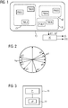
- the Figure 1 shows a schematic representation of an energy supply network 10 which is equipped with a large number of measuring devices PMU1 to PMU7.
- the measuring devices PMU1 to PMU7 are preferably pointer measuring devices that can detect electrical voltage indicators of conductor voltages and / or positive sequence voltages. Such measuring devices are also referred to in technical terms as "Phasor Measurement Units".
- the measuring devices PMU1 to PMU7 are connected to a monitoring device 20 and transmit their measured values to it.
- the measured values are preferably phase position values, which are identified by the reference symbols ⁇ 1 to ⁇ 7, and / or voltage vectors from all three phases, from which the associated positive sequence system component is determined and their respective phase position is used below as phase position value.
- the connection for the transmission of the phase position values ⁇ 1 to ⁇ 7 is for reasons of clarity in the Figure 1 not shown in detail.
- the Figure 2 shows the example of the measuring devices PMU1 to PMU7 according to FIG Figure 1 measured pointer measured values with the corresponding phase position values ⁇ 1 to ⁇ 7.
- FIG. 11 shows an exemplary embodiment for a monitoring device 20 which, in the arrangement according to FIG Figure 1 can be used to monitor the power supply network 10.
- the monitoring device 20 comprises a computer 21 and a memory 22.
- An island recognition program IP is stored in the memory 22 which, when executed by the computer 21, enables the computer 21 to operate the energy supply network 10 in accordance with Figure 1 to examine for possible island formation.
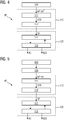
- FIG. 11 shows, in the form of a flow chart, an exemplary embodiment of an island recognition program IP that is generated by the monitoring device 20 according to FIG Figure 3 for monitoring the energy supply network 10 according to Figure 1 can be executed.
- the island detection program IP according to Figure 4 has a detection step 100 which is used to detect the data from the measuring devices PMU1 to PMU7 according to Figure 1 transmitted phase position values ⁇ 1 to ⁇ 7 is used.
- phase position values ⁇ 1 to ⁇ 7 acquired in acquisition step 100 arrive at a sorting procedure 110, which includes a presorting step 111 and a re-sorting procedure 112.
- the phase position values ⁇ 1 to ⁇ 7 are sorted according to size, forming a presorted phase position sequence VSR.
- the presorted phase position sequence VSR arrives at the re-sorting procedure 112, in which a re-sorting of the presorted phase position sequence takes place while forming a sorted phase position sequence SR.
- the alarm threshold value AS is 60 °.
- phase position sequence is rearranged by increasing the smallest phase position value (here -170 °) by 360 °.
- the increase by 360 ° now results in a phase position value of + 190 °, which is sorted accordingly in the phase position sequence.
- phase position sequence is rearranged again by increasing the phase position value ⁇ 2 by 360 ° and re-sorting it accordingly in the phase position sequence.
- a differentiation step 121 and a comparison step 122 are carried out in accordance with the sorted phase position sequence SR for each phase position value following a predetermined start phase value.
- the phase difference here is 46 °.
- step 122 it is checked whether the amount of the phase position difference exceeds or falls below the alarm threshold value AS.
- the next difference formation step 121 is carried out with the same reference phase value ⁇ 7.
- the phase position difference between the current reference phase value is now ⁇ 7 and the subsequent phase position value ⁇ 4 are formed and compared with the alarm threshold value AS.
- the difference here is 85 ° and exceeds the alarm threshold value AS. Because the alarm threshold value AS is exceeded, it is assumed that the phase position value ⁇ 4 with the two phase position values ⁇ 6 and ⁇ 7 is no longer synchronous (or sufficiently synchronous) and to a separate island within the power supply network 10 according to Figure 1 belongs.
- the phase position value ⁇ 4 is now set as the new reference phase value, and work continues with the subtraction step 121 for the next following phase position value ⁇ 5 using the now new reference phase value ⁇ 4.
- the difference between the phase position values ⁇ 5 and ⁇ 4 is subsequently formed, and in the subsequent comparison step 122 the determined difference becomes
- phase position difference between the phase position value ⁇ 3 and the reference phase value ⁇ 4 exceeds the alarm threshold value AS, so that it is now established that the phase position value ⁇ 3 belongs to a third island within the energy supply network 10.
- the phase position value ⁇ 3 is now set as the new reference phase value and the method is continued for the subsequent phase position value ⁇ 1.
- phase position value ⁇ 1 is assigned to the island of the phase position value ⁇ 3 and the method is continued with the reference phase value ⁇ 3.
- phase position difference from the current reference phase value ⁇ 3 is small enough that the phase position value ⁇ 2 is also assigned to the island with the phase position values ⁇ 1 and ⁇ 3.
- the analysis procedure 120 After the sorted phase position sequence SR has been processed, the analysis procedure 120 thus comes to the result that an island detection signal IS is to be generated, which indicates island formation within the energy supply network 10.
- the analysis procedure 120 generates an island data set IDS, which indicates that there are a total of three islands or three sub-networks within the energy supply network 10, each of which works synchronously (or sufficiently synchronously).
- the selection of the start phase value for the analysis procedure 120 is otherwise arbitrary; instead of the largest phase position value or the smallest phase position value, an average phase value can also be selected.
- FIG. 3 shows a further exemplary embodiment of an island recognition program IP which is generated by the computer 21 according to FIG Figure 1 can be used.
- a frequency and / or frequency change evaluation module 400 which is carried out before the execution of the acquisition step 100 and first carries out a preliminary check as to whether frequency values and / or frequency change values of the measuring devices PMU1 to PMU7 for asynchronicity or island formation within the energy supply network 10 according to Figure 1 indicate.
- the subsequent analysis of the phase position values of the measuring devices PMU1 to PMU7 is carried out only when it is determined in the course of the execution of the frequency and / or frequency change evaluation module 400 that islands are likely to have formed.
- the synchronous subnetworks identified by the frequency and / or frequency change evaluation module 400 are each individually further analyzed for islands within the respective subnetworks, as was done in connection with FIG Figure 4 has been explained.
- phase position values independently of the work result of the frequency and / or frequency change evaluation module 400, as was done in connection with FIG Figure 4 has been explained above. In this case, any island formation can be recognized even with very small frequency deviations.
Landscapes
- Engineering & Computer Science (AREA)
- Power Engineering (AREA)
- Physics & Mathematics (AREA)
- General Physics & Mathematics (AREA)
- Data Exchanges In Wide-Area Networks (AREA)
- Alarm Systems (AREA)
Priority Applications (4)
| Application Number | Priority Date | Filing Date | Title |
|---|---|---|---|
| EP18164941.9A EP3547481B1 (de) | 2018-03-29 | 2018-03-29 | Verfahren zum überwachen eines elektrischen netzes |
| ES18164941T ES2863376T3 (es) | 2018-03-29 | 2018-03-29 | Procedimiento para monitorear una red eléctrica |
| PL18164941T PL3547481T3 (pl) | 2018-03-29 | 2018-03-29 | Sposób monitorowania sieci elektrycznej |
| US16/369,230 US11002775B2 (en) | 2018-03-29 | 2019-03-29 | Method for monitoring an electrical network |
Applications Claiming Priority (1)
| Application Number | Priority Date | Filing Date | Title |
|---|---|---|---|
| EP18164941.9A EP3547481B1 (de) | 2018-03-29 | 2018-03-29 | Verfahren zum überwachen eines elektrischen netzes |
Publications (2)
| Publication Number | Publication Date |
|---|---|
| EP3547481A1 EP3547481A1 (de) | 2019-10-02 |
| EP3547481B1 true EP3547481B1 (de) | 2021-01-13 |
Family
ID=61837685
Family Applications (1)
| Application Number | Title | Priority Date | Filing Date |
|---|---|---|---|
| EP18164941.9A Active EP3547481B1 (de) | 2018-03-29 | 2018-03-29 | Verfahren zum überwachen eines elektrischen netzes |
Country Status (4)
| Country | Link |
|---|---|
| US (1) | US11002775B2 (pl) |
| EP (1) | EP3547481B1 (pl) |
| ES (1) | ES2863376T3 (pl) |
| PL (1) | PL3547481T3 (pl) |
Families Citing this family (3)
| Publication number | Priority date | Publication date | Assignee | Title |
|---|---|---|---|---|
| DE102019133405A1 (de) | 2019-12-06 | 2021-06-10 | Sma Solar Technology Ag | Verfahren und Anordnung zum Ermitteln einer Lastflusskarte innerhalb eines Wechselspannungs-Energieversorgungsnetzes |
| US10942204B1 (en) * | 2020-10-27 | 2021-03-09 | North China Electric Power University | Taylor weighted least squares method for estimating synchrophasor |
| CN121027718B (zh) * | 2025-09-05 | 2026-04-17 | 检安建设(广东)股份有限公司 | 一种电气线路故障智能检测方法、装置、设备及存储介质 |
Family Cites Families (11)
| Publication number | Priority date | Publication date | Assignee | Title |
|---|---|---|---|---|
| JP3029185B2 (ja) * | 1994-04-12 | 2000-04-04 | キヤノン株式会社 | 単独運転防止装置、それを用いた分散型発電装置及び発電システム |
| US6429546B1 (en) * | 1998-11-20 | 2002-08-06 | Georgia Tech Research Corporation | Systems and methods for preventing islanding of grid-connected electrical power systems |
| US9077208B2 (en) * | 2011-12-30 | 2015-07-07 | Schneider Electric USA, Inc. | Method of detecting instability in islanded electrical systems |
| US9293949B2 (en) * | 2012-02-06 | 2016-03-22 | Montana Tech Of The University Of Montana | Electric power grid signal processing methods, oscillatory mode estimation methods and mode shape estimation methods |
| US9804209B2 (en) | 2012-02-29 | 2017-10-31 | Siemens Aktiengesellschaft | Monitoring an electrical power supply network |
| US9124095B1 (en) * | 2013-02-15 | 2015-09-01 | Ideal Power Inc. | Islanding detection in power converters |
| US9331487B2 (en) * | 2013-03-14 | 2016-05-03 | Rockwell Automation Technologies, Inc. | Method and apparatus for islanding detection for grid tie converters |
| EP2806280A1 (en) * | 2013-05-21 | 2014-11-26 | ABB Research Ltd. | Detecting electrical islands using wide-area measurements |
| US9520819B2 (en) * | 2014-02-28 | 2016-12-13 | General Electric Company | System and method for controlling a power generation system based on a detected islanding event |
| US9997920B2 (en) * | 2014-06-11 | 2018-06-12 | Sinewatts, Inc. | System and method for islanding detection and prevention in distributed generation |
| US10833507B2 (en) * | 2016-11-29 | 2020-11-10 | Schweitzer Engineering Laboratories, Inc. | Island detection and control of a microgrid |
-
2018
- 2018-03-29 PL PL18164941T patent/PL3547481T3/pl unknown
- 2018-03-29 EP EP18164941.9A patent/EP3547481B1/de active Active
- 2018-03-29 ES ES18164941T patent/ES2863376T3/es active Active
-
2019
- 2019-03-29 US US16/369,230 patent/US11002775B2/en active Active
Non-Patent Citations (1)
| Title |
|---|
| None * |
Also Published As
| Publication number | Publication date |
|---|---|
| PL3547481T3 (pl) | 2021-07-12 |
| ES2863376T3 (es) | 2021-10-11 |
| US20190302158A1 (en) | 2019-10-03 |
| US11002775B2 (en) | 2021-05-11 |
| EP3547481A1 (de) | 2019-10-02 |
Similar Documents
| Publication | Publication Date | Title |
|---|---|---|
| EP3379273B1 (de) | Verfahren, einrichtung und system zum ermitteln des fehlerortes eines fehlers auf einer leitung eines elektrischen energieversorgungsnetzes | |
| EP3955012B1 (de) | Verfahren und einrichtung zum ermitteln des fehlerortes eines fehlers auf einer leitung eines elektrischen energieversorgungsnetzes | |
| EP2845286B1 (de) | Fehlererkennung in energieversorgungsnetzen | |
| DE4333257A1 (de) | Verfahren zum Gewinnen eines Fehlerkennzeichnungs-Signals | |
| EP3547481B1 (de) | Verfahren zum überwachen eines elektrischen netzes | |
| DE112007000473T5 (de) | Stromdifferential-Relaisvorrichtung, Signalverarbeitungsverfahren hierfür und Energieübertragungsleitungsschutzsystem | |
| DE102018122248A1 (de) | Verfahren und Systeme zur Erdschlusserfassung in einem Leistungsverteilungssystem | |
| EP2903112B1 (de) | Verfahren zur erkennung von störlichtbögen und schutzschalter | |
| DE102016113624A1 (de) | Motorantrieb mit Funktion zum Detektieren von Schaltungsabnormalitäten aufgrund eindringender Fremdstoffe, bevor es zu einer erheblichen Abnormalität kommt | |
| WO2008134995A1 (de) | Verfahren und vorrichtung zur erfassung eines fehlers in einem elektrischen versorgungsnetz | |
| EP3108554B1 (de) | Differentialschutzverfahren und differentialschutzeinrichtung | |
| DE102018208118A1 (de) | Verfahren und Vorrichtung zum Authentifizieren einer über einen Bus übertragenen Nachricht | |
| EP3451477B1 (de) | Erkennen eines fehlers in einem gleichstromübertragungssystem | |
| DE69231372T2 (de) | Verfahren zur Gewinnung einer logischen Beschreibung von einem abgetasteten Analogsignal | |
| WO1997020219A2 (de) | Verfahren zum gewinnen von fehlerbehaftete schleifen in einem mehrphasigen elektrischen energieversorgungsnetz kennzeichnenden signalen | |
| CH706968B1 (de) | Erfassung von Fehlern innerhalb eines Schaltkreises in Generatorstatoren. | |
| EP1341284B1 (de) | Plausibilitätsprüfung von Spannungswandlern in Unterstationen | |
| DE102017129168A1 (de) | Verfahren zur Spektrumklassifizierung, Verfahren zur Klassifizierung sowie Empfangsvorrichtung | |
| EP3994473B1 (de) | Auswerten von teilentladungssignalen | |
| DE102023109671A1 (de) | Fehlerstromschutzeinrichtung, Stromverteilungssystem und Verfahren zur Auslösesteuerung | |
| EP2057726B1 (de) | Differentialschutzverfahren und differentialschutzeinrichtung | |
| AT522128B1 (de) | Überprüfen von Mantelspannungsbegrenzern | |
| EP3300201A1 (de) | Verfahren und einrichtung zum überwachen einer energieübertragungseinrichtung | |
| EP3527996A1 (de) | Messanordnung und verfahren zum messen elektrischer signale | |
| DE102018113627A1 (de) | Verfahren und Vorrichtung zur Fehlerdiagnose in einem eine Ringstruktur aufweisenden elektrischen Netz sowie Computerprogrammprodukt |
Legal Events
| Date | Code | Title | Description |
|---|---|---|---|
| PUAI | Public reference made under article 153(3) epc to a published international application that has entered the european phase |
Free format text: ORIGINAL CODE: 0009012 |
|
| STAA | Information on the status of an ep patent application or granted ep patent |
Free format text: STATUS: THE APPLICATION HAS BEEN PUBLISHED |
|
| AK | Designated contracting states |
Kind code of ref document: A1 Designated state(s): AL AT BE BG CH CY CZ DE DK EE ES FI FR GB GR HR HU IE IS IT LI LT LU LV MC MK MT NL NO PL PT RO RS SE SI SK SM TR |
|
| AX | Request for extension of the european patent |
Extension state: BA ME |
|
| STAA | Information on the status of an ep patent application or granted ep patent |
Free format text: STATUS: REQUEST FOR EXAMINATION WAS MADE |
|
| 17P | Request for examination filed |
Effective date: 20200330 |
|
| RBV | Designated contracting states (corrected) |
Designated state(s): AL AT BE BG CH CY CZ DE DK EE ES FI FR GB GR HR HU IE IS IT LI LT LU LV MC MK MT NL NO PL PT RO RS SE SI SK SM TR |
|
| GRAP | Despatch of communication of intention to grant a patent |
Free format text: ORIGINAL CODE: EPIDOSNIGR1 |
|
| STAA | Information on the status of an ep patent application or granted ep patent |
Free format text: STATUS: GRANT OF PATENT IS INTENDED |
|
| INTG | Intention to grant announced |
Effective date: 20200910 |
|
| GRAS | Grant fee paid |
Free format text: ORIGINAL CODE: EPIDOSNIGR3 |
|
| GRAA | (expected) grant |
Free format text: ORIGINAL CODE: 0009210 |
|
| STAA | Information on the status of an ep patent application or granted ep patent |
Free format text: STATUS: THE PATENT HAS BEEN GRANTED |
|
| AK | Designated contracting states |
Kind code of ref document: B1 Designated state(s): AL AT BE BG CH CY CZ DE DK EE ES FI FR GB GR HR HU IE IS IT LI LT LU LV MC MK MT NL NO PL PT RO RS SE SI SK SM TR |
|
| REG | Reference to a national code |
Ref country code: GB Ref legal event code: FG4D Free format text: NOT ENGLISH |
|
| REG | Reference to a national code |
Ref country code: CH Ref legal event code: EP |
|
| REG | Reference to a national code |
Ref country code: DE Ref legal event code: R096 Ref document number: 502018003621 Country of ref document: DE |
|
| REG | Reference to a national code |
Ref country code: IE Ref legal event code: FG4D Free format text: LANGUAGE OF EP DOCUMENT: GERMAN |
|
| REG | Reference to a national code |
Ref country code: AT Ref legal event code: REF Ref document number: 1355267 Country of ref document: AT Kind code of ref document: T Effective date: 20210215 |
|
| REG | Reference to a national code |
Ref country code: NL Ref legal event code: FP |
|
| REG | Reference to a national code |
Ref country code: LT Ref legal event code: MG9D |
|
| PG25 | Lapsed in a contracting state [announced via postgrant information from national office to epo] |
Ref country code: BG Free format text: LAPSE BECAUSE OF FAILURE TO SUBMIT A TRANSLATION OF THE DESCRIPTION OR TO PAY THE FEE WITHIN THE PRESCRIBED TIME-LIMIT Effective date: 20210413 Ref country code: GR Free format text: LAPSE BECAUSE OF FAILURE TO SUBMIT A TRANSLATION OF THE DESCRIPTION OR TO PAY THE FEE WITHIN THE PRESCRIBED TIME-LIMIT Effective date: 20210414 Ref country code: HR Free format text: LAPSE BECAUSE OF FAILURE TO SUBMIT A TRANSLATION OF THE DESCRIPTION OR TO PAY THE FEE WITHIN THE PRESCRIBED TIME-LIMIT Effective date: 20210113 Ref country code: FI Free format text: LAPSE BECAUSE OF FAILURE TO SUBMIT A TRANSLATION OF THE DESCRIPTION OR TO PAY THE FEE WITHIN THE PRESCRIBED TIME-LIMIT Effective date: 20210113 Ref country code: PT Free format text: LAPSE BECAUSE OF FAILURE TO SUBMIT A TRANSLATION OF THE DESCRIPTION OR TO PAY THE FEE WITHIN THE PRESCRIBED TIME-LIMIT Effective date: 20210513 Ref country code: NO Free format text: LAPSE BECAUSE OF FAILURE TO SUBMIT A TRANSLATION OF THE DESCRIPTION OR TO PAY THE FEE WITHIN THE PRESCRIBED TIME-LIMIT Effective date: 20210413 Ref country code: LT Free format text: LAPSE BECAUSE OF FAILURE TO SUBMIT A TRANSLATION OF THE DESCRIPTION OR TO PAY THE FEE WITHIN THE PRESCRIBED TIME-LIMIT Effective date: 20210113 |
|
| PG25 | Lapsed in a contracting state [announced via postgrant information from national office to epo] |
Ref country code: RS Free format text: LAPSE BECAUSE OF FAILURE TO SUBMIT A TRANSLATION OF THE DESCRIPTION OR TO PAY THE FEE WITHIN THE PRESCRIBED TIME-LIMIT Effective date: 20210113 Ref country code: LV Free format text: LAPSE BECAUSE OF FAILURE TO SUBMIT A TRANSLATION OF THE DESCRIPTION OR TO PAY THE FEE WITHIN THE PRESCRIBED TIME-LIMIT Effective date: 20210113 Ref country code: SE Free format text: LAPSE BECAUSE OF FAILURE TO SUBMIT A TRANSLATION OF THE DESCRIPTION OR TO PAY THE FEE WITHIN THE PRESCRIBED TIME-LIMIT Effective date: 20210113 |
|
| PG25 | Lapsed in a contracting state [announced via postgrant information from national office to epo] |
Ref country code: IS Free format text: LAPSE BECAUSE OF FAILURE TO SUBMIT A TRANSLATION OF THE DESCRIPTION OR TO PAY THE FEE WITHIN THE PRESCRIBED TIME-LIMIT Effective date: 20210513 |
|
| REG | Reference to a national code |
Ref country code: ES Ref legal event code: FG2A Ref document number: 2863376 Country of ref document: ES Kind code of ref document: T3 Effective date: 20211011 |
|
| REG | Reference to a national code |
Ref country code: DE Ref legal event code: R097 Ref document number: 502018003621 Country of ref document: DE |
|
| PG25 | Lapsed in a contracting state [announced via postgrant information from national office to epo] |
Ref country code: MC Free format text: LAPSE BECAUSE OF FAILURE TO SUBMIT A TRANSLATION OF THE DESCRIPTION OR TO PAY THE FEE WITHIN THE PRESCRIBED TIME-LIMIT Effective date: 20210113 Ref country code: EE Free format text: LAPSE BECAUSE OF FAILURE TO SUBMIT A TRANSLATION OF THE DESCRIPTION OR TO PAY THE FEE WITHIN THE PRESCRIBED TIME-LIMIT Effective date: 20210113 Ref country code: CZ Free format text: LAPSE BECAUSE OF FAILURE TO SUBMIT A TRANSLATION OF THE DESCRIPTION OR TO PAY THE FEE WITHIN THE PRESCRIBED TIME-LIMIT Effective date: 20210113 Ref country code: SM Free format text: LAPSE BECAUSE OF FAILURE TO SUBMIT A TRANSLATION OF THE DESCRIPTION OR TO PAY THE FEE WITHIN THE PRESCRIBED TIME-LIMIT Effective date: 20210113 |
|
| REG | Reference to a national code |
Ref country code: CH Ref legal event code: PL |
|
| PLBE | No opposition filed within time limit |
Free format text: ORIGINAL CODE: 0009261 |
|
| STAA | Information on the status of an ep patent application or granted ep patent |
Free format text: STATUS: NO OPPOSITION FILED WITHIN TIME LIMIT |
|
| PG25 | Lapsed in a contracting state [announced via postgrant information from national office to epo] |
Ref country code: DK Free format text: LAPSE BECAUSE OF FAILURE TO SUBMIT A TRANSLATION OF THE DESCRIPTION OR TO PAY THE FEE WITHIN THE PRESCRIBED TIME-LIMIT Effective date: 20210113 Ref country code: SK Free format text: LAPSE BECAUSE OF FAILURE TO SUBMIT A TRANSLATION OF THE DESCRIPTION OR TO PAY THE FEE WITHIN THE PRESCRIBED TIME-LIMIT Effective date: 20210113 Ref country code: RO Free format text: LAPSE BECAUSE OF FAILURE TO SUBMIT A TRANSLATION OF THE DESCRIPTION OR TO PAY THE FEE WITHIN THE PRESCRIBED TIME-LIMIT Effective date: 20210113 |
|
| REG | Reference to a national code |
Ref country code: BE Ref legal event code: MM Effective date: 20210331 |
|
| 26N | No opposition filed |
Effective date: 20211014 |
|
| PG25 | Lapsed in a contracting state [announced via postgrant information from national office to epo] |
Ref country code: LU Free format text: LAPSE BECAUSE OF NON-PAYMENT OF DUE FEES Effective date: 20210329 Ref country code: LI Free format text: LAPSE BECAUSE OF NON-PAYMENT OF DUE FEES Effective date: 20210331 Ref country code: IE Free format text: LAPSE BECAUSE OF NON-PAYMENT OF DUE FEES Effective date: 20210329 Ref country code: CH Free format text: LAPSE BECAUSE OF NON-PAYMENT OF DUE FEES Effective date: 20210331 Ref country code: AL Free format text: LAPSE BECAUSE OF FAILURE TO SUBMIT A TRANSLATION OF THE DESCRIPTION OR TO PAY THE FEE WITHIN THE PRESCRIBED TIME-LIMIT Effective date: 20210113 Ref country code: FR Free format text: LAPSE BECAUSE OF NON-PAYMENT OF DUE FEES Effective date: 20210331 |
|
| PG25 | Lapsed in a contracting state [announced via postgrant information from national office to epo] |
Ref country code: SI Free format text: LAPSE BECAUSE OF FAILURE TO SUBMIT A TRANSLATION OF THE DESCRIPTION OR TO PAY THE FEE WITHIN THE PRESCRIBED TIME-LIMIT Effective date: 20210113 |
|
| PG25 | Lapsed in a contracting state [announced via postgrant information from national office to epo] |
Ref country code: IT Free format text: LAPSE BECAUSE OF FAILURE TO SUBMIT A TRANSLATION OF THE DESCRIPTION OR TO PAY THE FEE WITHIN THE PRESCRIBED TIME-LIMIT Effective date: 20210113 |
|
| PG25 | Lapsed in a contracting state [announced via postgrant information from national office to epo] |
Ref country code: IS Free format text: LAPSE BECAUSE OF FAILURE TO SUBMIT A TRANSLATION OF THE DESCRIPTION OR TO PAY THE FEE WITHIN THE PRESCRIBED TIME-LIMIT Effective date: 20210513 |
|
| PG25 | Lapsed in a contracting state [announced via postgrant information from national office to epo] |
Ref country code: BE Free format text: LAPSE BECAUSE OF NON-PAYMENT OF DUE FEES Effective date: 20210331 |
|
| GBPC | Gb: european patent ceased through non-payment of renewal fee |
Effective date: 20220329 |
|
| PG25 | Lapsed in a contracting state [announced via postgrant information from national office to epo] |
Ref country code: GB Free format text: LAPSE BECAUSE OF NON-PAYMENT OF DUE FEES Effective date: 20220329 |
|
| PG25 | Lapsed in a contracting state [announced via postgrant information from national office to epo] |
Ref country code: CY Free format text: LAPSE BECAUSE OF FAILURE TO SUBMIT A TRANSLATION OF THE DESCRIPTION OR TO PAY THE FEE WITHIN THE PRESCRIBED TIME-LIMIT Effective date: 20210113 |
|
| PG25 | Lapsed in a contracting state [announced via postgrant information from national office to epo] |
Ref country code: HU Free format text: LAPSE BECAUSE OF FAILURE TO SUBMIT A TRANSLATION OF THE DESCRIPTION OR TO PAY THE FEE WITHIN THE PRESCRIBED TIME-LIMIT; INVALID AB INITIO Effective date: 20180329 |
|
| PG25 | Lapsed in a contracting state [announced via postgrant information from national office to epo] |
Ref country code: MK Free format text: LAPSE BECAUSE OF FAILURE TO SUBMIT A TRANSLATION OF THE DESCRIPTION OR TO PAY THE FEE WITHIN THE PRESCRIBED TIME-LIMIT Effective date: 20210113 |
|
| REG | Reference to a national code |
Ref country code: AT Ref legal event code: MM01 Ref document number: 1355267 Country of ref document: AT Kind code of ref document: T Effective date: 20230329 |
|
| PG25 | Lapsed in a contracting state [announced via postgrant information from national office to epo] |
Ref country code: AT Free format text: LAPSE BECAUSE OF NON-PAYMENT OF DUE FEES Effective date: 20230329 |
|
| PG25 | Lapsed in a contracting state [announced via postgrant information from national office to epo] |
Ref country code: AT Free format text: LAPSE BECAUSE OF NON-PAYMENT OF DUE FEES Effective date: 20230329 |
|
| PG25 | Lapsed in a contracting state [announced via postgrant information from national office to epo] |
Ref country code: MT Free format text: LAPSE BECAUSE OF FAILURE TO SUBMIT A TRANSLATION OF THE DESCRIPTION OR TO PAY THE FEE WITHIN THE PRESCRIBED TIME-LIMIT Effective date: 20210113 |
|
| PGFP | Annual fee paid to national office [announced via postgrant information from national office to epo] |
Ref country code: PL Payment date: 20250324 Year of fee payment: 8 |
|
| PGFP | Annual fee paid to national office [announced via postgrant information from national office to epo] |
Ref country code: DE Payment date: 20250520 Year of fee payment: 8 |
|
| PGFP | Annual fee paid to national office [announced via postgrant information from national office to epo] |
Ref country code: ES Payment date: 20250620 Year of fee payment: 8 |
|
| PG25 | Lapsed in a contracting state [announced via postgrant information from national office to epo] |
Ref country code: TR Free format text: LAPSE BECAUSE OF FAILURE TO SUBMIT A TRANSLATION OF THE DESCRIPTION OR TO PAY THE FEE WITHIN THE PRESCRIBED TIME-LIMIT Effective date: 20210113 |
|
| PGFP | Annual fee paid to national office [announced via postgrant information from national office to epo] |
Ref country code: AT Payment date: 20260410 Year of fee payment: 5 |
|
| PGFP | Annual fee paid to national office [announced via postgrant information from national office to epo] |
Ref country code: NL Payment date: 20260309 Year of fee payment: 9 |