EP3547415A2 - 3d pattern cutting machine for lithium metal electrode - Google Patents
3d pattern cutting machine for lithium metal electrode Download PDFInfo
- Publication number
- EP3547415A2 EP3547415A2 EP18832390.1A EP18832390A EP3547415A2 EP 3547415 A2 EP3547415 A2 EP 3547415A2 EP 18832390 A EP18832390 A EP 18832390A EP 3547415 A2 EP3547415 A2 EP 3547415A2
- Authority
- EP
- European Patent Office
- Prior art keywords
- pattern
- mold
- lithium metal
- electrode
- punch
- Prior art date
- Legal status (The legal status is an assumption and is not a legal conclusion. Google has not performed a legal analysis and makes no representation as to the accuracy of the status listed.)
- Granted
Links
Images


Classifications
-
- H—ELECTRICITY
- H01—ELECTRIC ELEMENTS
- H01M—PROCESSES OR MEANS, e.g. BATTERIES, FOR THE DIRECT CONVERSION OF CHEMICAL ENERGY INTO ELECTRICAL ENERGY
- H01M4/00—Electrodes
- H01M4/02—Electrodes composed of, or comprising, active material
- H01M4/13—Electrodes for accumulators with non-aqueous electrolyte, e.g. for lithium-accumulators; Processes of manufacture thereof
- H01M4/139—Processes of manufacture
- H01M4/1395—Processes of manufacture of electrodes based on metals, Si or alloys
-
- B—PERFORMING OPERATIONS; TRANSPORTING
- B21—MECHANICAL METAL-WORKING WITHOUT ESSENTIALLY REMOVING MATERIAL; PUNCHING METAL
- B21D—WORKING OR PROCESSING OF SHEET METAL OR METAL TUBES, RODS OR PROFILES WITHOUT ESSENTIALLY REMOVING MATERIAL; PUNCHING METAL
- B21D22/00—Shaping without cutting, by stamping, spinning, or deep-drawing
- B21D22/02—Stamping using rigid devices or tools
- B21D22/04—Stamping using rigid devices or tools for dimpling
-
- B—PERFORMING OPERATIONS; TRANSPORTING
- B21—MECHANICAL METAL-WORKING WITHOUT ESSENTIALLY REMOVING MATERIAL; PUNCHING METAL
- B21D—WORKING OR PROCESSING OF SHEET METAL OR METAL TUBES, RODS OR PROFILES WITHOUT ESSENTIALLY REMOVING MATERIAL; PUNCHING METAL
- B21D28/00—Shaping by press-cutting; Perforating
- B21D28/02—Punching blanks or articles with or without obtaining scrap; Notching
- B21D28/14—Dies
-
- B—PERFORMING OPERATIONS; TRANSPORTING
- B26—HAND CUTTING TOOLS; CUTTING; SEVERING
- B26F—PERFORATING; PUNCHING; CUTTING-OUT; STAMPING-OUT; SEVERING BY MEANS OTHER THAN CUTTING
- B26F1/00—Perforating; Punching; Cutting-out; Stamping-out; Apparatus therefor
- B26F1/38—Cutting-out; Stamping-out
- B26F1/44—Cutters therefor; Dies therefor
-
- H—ELECTRICITY
- H01—ELECTRIC ELEMENTS
- H01M—PROCESSES OR MEANS, e.g. BATTERIES, FOR THE DIRECT CONVERSION OF CHEMICAL ENERGY INTO ELECTRICAL ENERGY
- H01M4/00—Electrodes
- H01M4/02—Electrodes composed of, or comprising, active material
- H01M4/04—Processes of manufacture in general
-
- H—ELECTRICITY
- H01—ELECTRIC ELEMENTS
- H01M—PROCESSES OR MEANS, e.g. BATTERIES, FOR THE DIRECT CONVERSION OF CHEMICAL ENERGY INTO ELECTRICAL ENERGY
- H01M4/00—Electrodes
- H01M4/02—Electrodes composed of, or comprising, active material
- H01M4/36—Selection of substances as active materials, active masses, active liquids
- H01M4/38—Selection of substances as active materials, active masses, active liquids of elements or alloys
- H01M4/381—Alkaline or alkaline earth metals elements
- H01M4/382—Lithium
-
- B—PERFORMING OPERATIONS; TRANSPORTING
- B26—HAND CUTTING TOOLS; CUTTING; SEVERING
- B26F—PERFORATING; PUNCHING; CUTTING-OUT; STAMPING-OUT; SEVERING BY MEANS OTHER THAN CUTTING
- B26F1/00—Perforating; Punching; Cutting-out; Stamping-out; Apparatus therefor
- B26F1/38—Cutting-out; Stamping-out
- B26F1/44—Cutters therefor; Dies therefor
- B26F2001/4418—Cutters therefor; Dies therefor combining cutting and embossing operations
-
- B—PERFORMING OPERATIONS; TRANSPORTING
- B26—HAND CUTTING TOOLS; CUTTING; SEVERING
- B26F—PERFORATING; PUNCHING; CUTTING-OUT; STAMPING-OUT; SEVERING BY MEANS OTHER THAN CUTTING
- B26F1/00—Perforating; Punching; Cutting-out; Stamping-out; Apparatus therefor
- B26F1/38—Cutting-out; Stamping-out
- B26F1/44—Cutters therefor; Dies therefor
- B26F2001/4463—Methods and devices for rule setting, fixation, preparing cutting dies
-
- B—PERFORMING OPERATIONS; TRANSPORTING
- B26—HAND CUTTING TOOLS; CUTTING; SEVERING
- B26F—PERFORATING; PUNCHING; CUTTING-OUT; STAMPING-OUT; SEVERING BY MEANS OTHER THAN CUTTING
- B26F1/00—Perforating; Punching; Cutting-out; Stamping-out; Apparatus therefor
- B26F1/38—Cutting-out; Stamping-out
- B26F1/44—Cutters therefor; Dies therefor
- B26F2001/4481—Cutters therefor; Dies therefor having special lateral or edge outlines or special surface shapes, e.g. apertures
-
- H—ELECTRICITY
- H01—ELECTRIC ELEMENTS
- H01M—PROCESSES OR MEANS, e.g. BATTERIES, FOR THE DIRECT CONVERSION OF CHEMICAL ENERGY INTO ELECTRICAL ENERGY
- H01M10/00—Secondary cells; Manufacture thereof
- H01M10/05—Accumulators with non-aqueous electrolyte
- H01M10/052—Li-accumulators
-
- H—ELECTRICITY
- H01—ELECTRIC ELEMENTS
- H01M—PROCESSES OR MEANS, e.g. BATTERIES, FOR THE DIRECT CONVERSION OF CHEMICAL ENERGY INTO ELECTRICAL ENERGY
- H01M10/00—Secondary cells; Manufacture thereof
- H01M10/05—Accumulators with non-aqueous electrolyte
- H01M10/052—Li-accumulators
- H01M10/0525—Rocking-chair batteries, i.e. batteries with lithium insertion or intercalation in both electrodes; Lithium-ion batteries
-
- H—ELECTRICITY
- H01—ELECTRIC ELEMENTS
- H01M—PROCESSES OR MEANS, e.g. BATTERIES, FOR THE DIRECT CONVERSION OF CHEMICAL ENERGY INTO ELECTRICAL ENERGY
- H01M4/00—Electrodes
- H01M4/02—Electrodes composed of, or comprising, active material
- H01M2004/021—Physical characteristics, e.g. porosity, surface area
-
- Y—GENERAL TAGGING OF NEW TECHNOLOGICAL DEVELOPMENTS; GENERAL TAGGING OF CROSS-SECTIONAL TECHNOLOGIES SPANNING OVER SEVERAL SECTIONS OF THE IPC; TECHNICAL SUBJECTS COVERED BY FORMER USPC CROSS-REFERENCE ART COLLECTIONS [XRACs] AND DIGESTS
- Y02—TECHNOLOGIES OR APPLICATIONS FOR MITIGATION OR ADAPTATION AGAINST CLIMATE CHANGE
- Y02E—REDUCTION OF GREENHOUSE GAS [GHG] EMISSIONS, RELATED TO ENERGY GENERATION, TRANSMISSION OR DISTRIBUTION
- Y02E60/00—Enabling technologies; Technologies with a potential or indirect contribution to GHG emissions mitigation
- Y02E60/10—Energy storage using batteries
Definitions
- the present invention relates to a 3D pattern puncher for a lithium metal electrode, and more particularly, to a 3D pattern puncher for a lithium metal electrode, in which a 3D pattern mold of a polymer material is attached to a mold which punches a lithium metal electrode into unit electrodes, or the lithium metal electrode is punched into unit electrodes by making the mold itself as a polymer material having 3D patterns, and at the same time, 3D patterns can be engraved on the surface of the unit electrodes.
- a prismatic secondary battery and a pouch-type secondary battery that can be applied to products such as mobile phones with a small thickness.
- a lithium ion battery having high energy density, discharge voltage, and output stability, and a lithium ion polymer battery.
- a secondary battery is manufactured as follows. First of all, an active material is applied to the surface of a current collector to form a positive electrode and a negative electrode, and a separator is interposed therebetween to make an electrode assembly. Then the electrode assembly is mounted at the inside of a pouch type case of a cylindrical or rectangular metal can or aluminum laminate sheet, and a liquid electrolyte is injected or impregnated into the electrode assembly to thereby make a secondary battery. Sometimes a solid electrolyte may also be used.
- a carbon material such as graphite is used as a negative electrode of a lithium secondary battery, but it may be made of lithium metal.
- Lithium used as a negative electrode has a low density of 0.54 g/cm 3 and a standard reduction potential of -3.045 V SHE , which is very low, and thus it is most popular as an electrode material of a high energy density battery.
- the passive film is formed by reaction with the organic electrolyte, and as oxidation (dissolution) and reduction (deposition) reactions of lithium on the lithium metal surface during charging and discharging are repeated unevenly, the formation and growth of the passive film is extremely severe.
- lithium ions are grown in the form of needles on the surface of the lithium metal to thereby form a dendrite (lithium resin phase), which shortens the life of the battery, resulting in short circuit between the electrodes.
- the lithium metal has a capacity of about 3860 mAh/g per unit weight, but it is difficult to commercialize it due to the continuous reaction with the electrolyte in the battery and the resinous growth of lithium due to its life.
- a method of engraving a 3D pattern on a lithium metal electrode involves rolling a 3D pattern embossing on a roller.
- the 3D pattern is engraved on the surface of the lithium metal electrode by letting the roller having the 3D pattern of the shape that it wants to carve to pass over the lithium metal electrode at a constant pressure.
- FIG. 1 is a schematic view showing a method of engraving a 3D pattern 2 on a lithium metal electrode 3 using a 3D pattern roller 1 according to a conventional art.
- the 3D pattern roller 1 is formed of a material having a cube-like pattern 2 on its surface and being harder than lithium metal.
- a cubic 3D pattern is engraved on the surface of the lithium metal electrode 3 at a depressed angle.
- An object of the present invention is to solve the above-mentioned problems, and it is an object of the present invention to provide a 3D pattern puncher which can easily change 3D patterns when desiring to engrave other types of patterns on the surface of the lithium metal electrode, has a long replacement cycle due to a high releasability from a lithium metal, and has a constant engraved 3D pattern shape.
- Another object of the present invention is to provide a method of manufacturing a lithium metal unit electrode using the 3D pattern puncher, and a lithium metal unit electrode manufactured by the method and a secondary battery using the same.
- a 3-dimensional (3D) pattern puncher for punching a lithium metal electrode as unit electrodes, including: a mold punch configured to move up and down with a mold suited to a size of the unit electrode; a die corresponding to the mold punch; a mold blade configured to be disposed at an edge of the mold punch and punch the lithium metal electrode as unit electrodes; and a 3D pattern positioned at an inner portion which is in contact with the die of the mold punch but does not have a blade formed thereon is provided.
- the mold punch may be any one of a mold made by sticking a 3D pattern mold made of a polymer material to a metal mold and a mold integrally made of a polymer material.
- the polymer material may be any one of polycarbonate, polyurethane acrylate, polyethylene terephthalate, polypropylene, polystyrene, and polybutylene terephthalate.
- a depth of the 3D pattern may be about 10 ⁇ m to about 100 ⁇ m.
- the 3D pattern may be engraved in one of an embossed shape or an engraved shape.
- the 3D pattern may have one of a mesh shape, a lamellar shape, an emboss shape, a linear shape, a circular shape, an elliptical shape, a polygonal shape, and a waveform shape.
- the 3D pattern puncher may further include a roller-shaped unwinder for continuously supplying a lithium metal electrode before being punched to a side surface of the die.
- a method for manufacturing a lithium metal unit electrode using the 3D pattern puncher including: positioning the lithium metal unit at the die; pushing the mold punch down and engraving 3D patterns on the lithium metal electrode; and releasing the lithium metal unit electrode by raising the mold punch is provided.
- a lithium metal unit electrode produced by the above method is provided.
- a secondary battery comprising the lithium metal unit electrode is provided.
- the lithium metal unit electrode is produced by the 3D pattern puncher provided in the present invention, the cost and time for 3D pattern replacement and cleaning are reduced, the shape of the 3D pattern is always constantly formed, and the 3D pattern is engraved while the punching process is performed to thereby improve the productivity of the lithium metal electrode.
- a 3D pattern puncher 100 includes: a mold punch 10 which moves up and down with a mold suited to the size of a unit electrode; a die 14 corresponding to the mold punch 10; a mold blade 11 disposed at an edge of the mold punch 10 to punch a lithium metal electrode 13 to become unit electrodes; and a 3D pattern 12 located on an inner portion of the mold punch 10 contacting the die 14 and formed in a non-bladed portion.
- the mold punch 10 shown in FIG. 2 has the mold blade 11 at its edge and the 3D pattern 12 formed inside.
- the die 14 is formed so as to engage with the mold blade 11 and the 3D pattern 12.
- the mold blade 11 is shown thick and pointed in FIG. 2 to emphasize the punch function, but actually functions as a thin blade.
- the lithium metal electrode 13 is positioned on the die 14, and the metal punch 10 is lowered and engaged with the die 14 to punch the lithium metal electrode 13 and simultaneously engrave a 3D pattern on the surface. It is preferable that the lithium metal electrode 13 is actually supplied continuously, and in order to emphasize the punching function, in FIG. 2 , an unwinder (not shown) for continuously supplying the lithium metal electrode 13 and a portion where the lithium metal electrode 13 is continually supplied are not shown.
- the object of the punching is the lithium metal electrode 13 having a capacity per unit weight of about 3860 mAh/g, which is very useful as a negative electrode.
- the pure lithium metal has a density of 0.54 g/cm 3 and has a problem of continuously reacting with the electrolyte to form dendrites.
- plastic processing and punching are easy, and it is easy to engrave 3D patterns on the surface.
- the size of the lithium metal unit electrode may vary depending on the size and capacity of the battery to be manufactured. It is also possible to bend the electrode at a certain level because of its easy processing property. Therefore, it can be used for stacked, folded, and stacked-folded type electrode assemblies.
- the mold punch 10 punches the lithium metal electrode 13 to become unit electrodes through a vertical movement.
- the vertical movement may be performed by a crank type, a gravity type, a hydraulic type, etc., and is not limited as long as it can apply a constant pressure while moving up and down.
- the mold punch 10 cuts the lithium metal electrode 13 into unit electrodes by applying a constant pressure to the lithium metal electrode 13 while descending from the top to the bottom with the lithium metal electrode 13 positioned on the die 14.
- the die 14 corresponding to the mold punch 10 has a size to engage with the mold punch 10 so that the mold punch 10 is lowered and engaged to punch the lithium metal electrode 13.
- An unwinder may be further provided on the side of the die 14.
- the lithium metal electrode 13 is continually supplied, the lithium metal electrode 13 is punched into unit electrodes in the mold punch 10 and the die 14, then if the mold punch goes upward, as the lithium metal electrode 13 before being punched pushes the punched electrode and is continually supplied, the lithium metal unit electrodes are continually produced.
- the die 14 is made of a metal material having a strength greater than that of the mold punch 10 since the impact of the mold punch 10 should be absorbed for a long time.
- the mold blade 11, which cuts the lithium metal electrode 13 into unit electrodes, is located at the edge of the mold punch 10.
- the mold blade 11 may be attached to the punch with a separate structure, but it is more preferable that the mold blade 11 is integrally formed with the mold, because the structure is simplified and it is advantageous in maintenance.
- the mold punch 10 has a size suitable for the lithium metal unit electrode and the mold blade 11 is positioned at the edge thereof to cut the lithium metal electrode 13 into unit electrode sizes. If the supplied lithium metal electrode 13 is supplied in the longitudinal direction with the same width as the unit electrode, the metal blade 11 is positioned only in the width direction, and if the lithium metal electrode 13 has the same length as the unit electrode and is supplied in the width direction, the mold blade 11 is positioned only in the longitudinal direction.
- the mold blade 11 should be positioned on all sides of the mold punch 10. In consideration of the productivity, it is preferable that the supplied lithium metal electrode 13 is aligned with the unit electrode in the length or width direction and the number of the mold blades 11 is reduced.
- a 3D pattern 12 is formed on the inner side of the mold punch 10 in contact with the lithium metal electrode 13.
- the 3D pattern 12 formed at the inner side comes into contact with the lithium metal electrode 13 to engrave the 3D pattern on the surface of the lithium metal electrode 13.
- the 3D pattern 12 may be embossed or engraved, and if the 3D pattern 12 engraved inside the punch mold punch 10 is embossed, an engraved 3D pattern is engraved on the lithium metal electrode 13, and if the 3D pattern 12 engraved inside the punch mold punch 10 is engraved, embossed 3D patterns are engraved on the lithium metal electrode 13.
- the 3D pattern 12 has a shape of any one of a mesh, a lamellar, an emboss, a linear, a circle, an ellipse, a polygon, and a waveform, and this may be variously selected according to the usage of the battery to be manufactured using the lithium metal electrode and the degree of dendrite growth inhibition to be given to the lithium metal electrode 13.
- the depth of the 3D pattern 12 is preferably 10 to 100 ⁇ m.
- the 3D pattern of the same depth is also formed in the lithium metal electrode 13 by the depth of the 3D pattern 12 of the mold punch 10, and the height of the lithium metal electrode 13 is usually within several hundreds of micrometers. And if the depth is less than 10 ⁇ m, the effect of suppressing the growth of dendrite is reduced. If the depth is more than 100 ⁇ m, the processability is deteriorated and it is difficult to continually engrave a constant pattern.
- the mold punch 10 of the present invention is either a mold in which a 3D pattern 12 mold of a polymer material is attached to a metal mold or a mold in which the mold is integrally made of a polymer material.
- the mold blade 11 is also integrally made of a metal material, and the 3D pattern 12 of a polymer material is attached on the inside of the mold.
- the mold blade 11 and the 3D pattern 12 are integrally made of a polymer material.
- the electrode is rolled using the roller 1 with the 3D pattern engraved.
- the rollers used in the rolling process usually use a metal which is heavy in order to have a certain pressure, which leads to a poor releasing property with lithium metal.
- the lithium metal electrode 3 is rolled with the roller, the lithium metal sticks to the roller due to its poor releasing property.
- the shape of the later engraved 3D pattern becomes different from the original shape. Therefore, in order to engrave a certain type of 3D pattern, it is necessary to clean the lithium metal sticking to the roller from time to time, which leads to an increase in production cost and time.
- the mold punch 10 of the present invention uses a 3D pattern 12 of a polymer material attached to a metal mold so that only the 3D pattern 12 mold needs to be replaced when the 3D pattern 12 is to be changed, and thus the above problem can be solved.
- it takes a lot of time and cost because the entire roller needs to be replaced.
- the replacement of the 3D pattern 12 according to the present invention requires only a replacement of the 3D pattern 12 mold made of a polymer material, and thus the costs and time can be saved. Even if the entire mold is made of a polymer material, the mold itself can be replaced with a mold having another 3D pattern (12), so that replacement of the entire metal roller is simpler and the cost is reduced.
- the releasability with the lithium metal electrode 13 is improved as compared with the prior art.
- the polymer material polycarbonate, polyurethane acrylate, polyethylene terephthalate, polypropylene, polystyrene, polybutylene terephthalate and the like can be used.
- polyurethane acrylate and polycarbonate have appropriate hardness and releasability, they may be preferred in that a precise pattern can be engraved on a metal and at the same time they can be reused without being broken even if the process of pressing on the lithium metal is repeated several times.
- the lithium metal has a soft nature and can be sufficiently punched because of its good processibility.
- the 3D pattern 12 mold having improved releasability does not need to be cleaned frequently since the lithium metal does not adhere well after the 3D pattern is engraved, and the 3D pattern engraved on the lithium metal electrode 13 can be more uniformly engraved.
- the method of forming the 3D pattern on the mold of the polymer material attached to the mold punch of the present invention is not particularly limited and any known method such as photolithography or soft lithography can be used.
- the soft lithography method include fine contact printing, decal transfer microlithography, photo-bonding mask method, replica molding, capillary-fine molding method, and the like.
- the replica molding method is suitable because the process is relatively simple, it is convenient for mass copying of a multidimensional structure and is suitable for mass production at a low cost.
- Replica molding is a replica of original information using a stamp made of flexible polymer.
- a silicon master mold 30 having a desired 3D pattern is prepared, and a polymer precursor 31 such as polyurethane acrylate is poured on the silicon master mold. The polymer is then cured to form a polyurethane acrylate mold 40.
- the thus formed polyurethane acrylate mold 40 is attached to the mold punch, and the lithium metal 50 is placed on the die.
- the mold punch is pushed down to be lowered from the top down, the 3D pattern is transferred to the lithium metal.
- a hydrophobic material, etc. may be thinly (several nm) coated on a polyurethane acrylate mold by using a spin coating scheme.
- the present invention also provides a method of manufacturing the lithium metal unit electrode 21 using the 3D pattern puncher 100.
- the method includes positioning the lithium metal electrode 13 on the die 14; engraving the 3D pattern on the surface of the lithium metal electrode 13 while pushing down the mold punch 10 from the top to the bottom; and releasing the lithium metal unit electrode 21 from the mold by lifting the mold punch 10.
- the present invention is also characterized in providing a lithium metal unit electrode 21 manufactured by the above manufacturing method and a secondary battery including the unit electrode.
- FIG. 3 schematically shows a lithium metal unit electrode 21 according to the present invention, and shows a square 3D pattern 22 in an enlarged view.
- the lithium metal unit electrode 21 manufactured according to the above method is more uniformly engraved with the 3D pattern, the generation of dendrite on the electrode surface becomes more uniform than when the same size and shape are formed by the conventional art.
- the generation of dendrite is made uniform, the lifetime and safety of the electrode are improved.
- the secondary battery using the electrode improves the lifetime and safety of the electrode, thereby improving battery life and cycle characteristics.
- a metal mold punch having a 3D pattern mold having a cubic 3D pattern of a size of 20 ⁇ m x 20 ⁇ m x 20 ⁇ m (width x breadth x depth) was prepared.
- the material of the 3D pattern mold was polyurethane acrylate.
- a lithium metal electrode having a thickness of 100 ⁇ m was placed on the die. While pushing down the punching mold from the top down, a 3D pattern was engraved on the surface of the lithium metal electrode and punched out. The punched lithium metal unit electrode was released from the mold, and the mold punch was moved up and down while continuously supplying the lithium metal electrode through the roller-type unwinder on the side of the die, thereby preparing 10 lithium metal unit electrodes.
- a lithium metal unit electrode was prepared in the same manner as in Example 1 except that a 3D pattern mold having a semi-spherical 3D pattern with a diameter of 20 ⁇ m was attached.
- the lithium metal unit electrode has been manufactured in the same manner as Example 1 except that the punch mold and 3D pattern integrally use a mold made of polyurethane acrylate.
- the lithium metal unit electrode has been manufactured in the same manner as Example 2 except that the punch mold and 3D pattern integrally use a mold made of polyurethane acrylate.
- a metal roller having a cubic 3D pattern with a size of 20 ⁇ m x 20 ⁇ m x 20 ⁇ m (width x breadth x depth) was prepared.
- a lithium metal electrode having a thickness of 100 ⁇ m was rolled with the roller and a 3D pattern was formed on the surface.
- a lithium metal electrode having a 3D pattern was cut to a predetermined size to prepare 10 lithium metal unit electrodes.
- a lithium metal unit electrode was prepared in the same manner as in Comparative Example 1 except that a roller having a hemispherical 3D pattern having a diameter of 20 ⁇ m was used.
- the lithium metal unit electrodes manufactured in the above embodiments and comparative examples are numbered in the order of manufacturing and the surface of the electrode is observed to show a certain degree of 3D pattern on Table 1. If the square or circular shape of the cross section of the 3D pattern is all correctly etched, and if the depth is constant, it is indicated by O, and if there is any distortion or non-constant depth of the square or circle, it is indicated by X. Also, when the pattern was accurately engraved but the outer cross-section of the punch electrode was not cut smoothly, it was marked separately as ⁇ beside ⁇ and X. [Table 1] Unit electrode no.
- Example 1 Example 2
- Example 3 Example 4 Comparative example 1 Comparative example 2 1 ⁇ ⁇ ⁇ ⁇ ⁇ ⁇ 2 ⁇ ⁇ ⁇ ⁇ ⁇ 3 ⁇ ⁇ ⁇ ⁇ ⁇ 4 ⁇ ⁇ ⁇ ⁇ ⁇ 5 ⁇ ⁇ ⁇ ⁇ ⁇ ⁇ 6 ⁇ ⁇ ⁇ ⁇ X ⁇ 7 ⁇ ⁇ ⁇ ⁇ X ⁇ 8 ⁇ ⁇ ⁇ ⁇ X X 9 ⁇ ⁇ , ⁇ ⁇ ⁇ X X 10 ⁇ , ⁇ ⁇ , ⁇ ⁇ ⁇ X X
- 3D pattern roller 2 3D pattern 3 : lithium metal electrode 100 : 3D pattern puncher 10 : mold punch 11 : mold blade 12 : 3D pattern 13 : lithium metal electrode 14 : die 21 : lithium metal unit electrode 22 : 3D pattern 30: silicon master mold 31: polymer precursor 40: polymer mold (soft mold) 50: lithium metal
Landscapes
- Engineering & Computer Science (AREA)
- Chemical & Material Sciences (AREA)
- Chemical Kinetics & Catalysis (AREA)
- Electrochemistry (AREA)
- General Chemical & Material Sciences (AREA)
- Mechanical Engineering (AREA)
- Manufacturing & Machinery (AREA)
- Materials Engineering (AREA)
- Life Sciences & Earth Sciences (AREA)
- Forests & Forestry (AREA)
- Battery Electrode And Active Subsutance (AREA)
- Punching Or Piercing (AREA)
- Perforating, Stamping-Out Or Severing By Means Other Than Cutting (AREA)
Abstract
Description
- This application claims the benefit of priority based on Korean Patent Application No.
10-2017-0086896 filed on Jul. 10, 2017 - The present invention relates to a 3D pattern puncher for a lithium metal electrode, and more particularly, to a 3D pattern puncher for a lithium metal electrode, in which a 3D pattern mold of a polymer material is attached to a mold which punches a lithium metal electrode into unit electrodes, or the lithium metal electrode is punched into unit electrodes by making the mold itself as a polymer material having 3D patterns, and at the same time, 3D patterns can be engraved on the surface of the unit electrodes.
- As the price of energy sources increases due to depletion of fossil fuels and the interest in environmental pollution is amplified, the demand for environmentally friendly alternative energy sources becomes an indispensable factor for future life. Especially, the demand for secondary batteries as an energy source is rapidly increasing.
- Typically, in terms of the shape of the battery, there is a high demand for a prismatic secondary battery and a pouch-type secondary battery that can be applied to products such as mobile phones with a small thickness. In terms of material, there is a high demand for a lithium ion battery having high energy density, discharge voltage, and output stability, and a lithium ion polymer battery.
- Generally, a secondary battery is manufactured as follows. First of all, an active material is applied to the surface of a current collector to form a positive electrode and a negative electrode, and a separator is interposed therebetween to make an electrode assembly. Then the electrode assembly is mounted at the inside of a pouch type case of a cylindrical or rectangular metal can or aluminum laminate sheet, and a liquid electrolyte is injected or impregnated into the electrode assembly to thereby make a secondary battery. Sometimes a solid electrolyte may also be used.
- In general, a carbon material such as graphite is used as a negative electrode of a lithium secondary battery, but it may be made of lithium metal. Lithium used as a negative electrode has a low density of 0.54 g/cm3 and a standard reduction potential of -3.045 VSHE, which is very low, and thus it is most popular as an electrode material of a high energy density battery. However, there are the following problems in applying the lithium metal to the negative electrode.
- Since the polymer electrolyte is chemically very active, the passive film is formed by reaction with the organic electrolyte, and as oxidation (dissolution) and reduction (deposition) reactions of lithium on the lithium metal surface during charging and discharging are repeated unevenly, the formation and growth of the passive film is extremely severe.
- As a result, not only the capacity of the battery is reduced during charging and discharging but also as the charging and discharging process is repeated, lithium ions are grown in the form of needles on the surface of the lithium metal to thereby form a dendrite (lithium resin phase), which shortens the life of the battery, resulting in short circuit between the electrodes.
- As described above, the lithium metal has a capacity of about 3860 mAh/g per unit weight, but it is difficult to commercialize it due to the continuous reaction with the electrolyte in the battery and the resinous growth of lithium due to its life.
- In order to solve this problem, various types of techniques have been developed. Recently, the increase in the surface area due to the formation of the 3D structure has been highlighted. By forming a 3D structure to maximize the surface area of the electrode, the area of contact of the lithium metal with the electrolyte is increased, thereby suppressing the growth of the dendrite.
- Generally, a method of engraving a 3D pattern on a lithium metal electrode involves rolling a 3D pattern embossing on a roller. The 3D pattern is engraved on the surface of the lithium metal electrode by letting the roller having the 3D pattern of the shape that it wants to carve to pass over the lithium metal electrode at a constant pressure.
-
FIG. 1 is a schematic view showing a method of engraving a 3D pattern 2 on a lithium metal electrode 3 using a3D pattern roller 1 according to a conventional art. The3D pattern roller 1 is formed of a material having a cube-like pattern 2 on its surface and being harder than lithium metal. When the3D pattern roller 1 passes over the lithium metal electrode 3 at a constant pressure, a cubic 3D pattern is engraved on the surface of the lithium metal electrode 3 at a depressed angle. - However, in this case, there is a problem that the rollers themselves have to be replaced if desiring to engrave different kinds of patterns. The bigger problem is that the rollers used in the rolling process are generally made of metal because they have to be heavily weighted to maintain a constant pressure, and thus an issue of releasing from lithium metal occurs. Lithium metal is a very fragile metal. Therefore, when rolling with a metal roller, it tends to stick to the roller. If this is repeated, the shape of the 3D pattern is not constantly engraved. To solve this problem, the rollers should be periodically cleaned.
- An object of the present invention is to solve the above-mentioned problems, and it is an object of the present invention to provide a 3D pattern puncher which can easily change 3D patterns when desiring to engrave other types of patterns on the surface of the lithium metal electrode, has a long replacement cycle due to a high releasability from a lithium metal, and has a constant engraved 3D pattern shape.
- Another object of the present invention is to provide a method of manufacturing a lithium metal unit electrode using the 3D pattern puncher, and a lithium metal unit electrode manufactured by the method and a secondary battery using the same.
- According to an aspect of the present invention, a 3-dimensional (3D) pattern puncher for punching a lithium metal electrode as unit electrodes, including: a mold punch configured to move up and down with a mold suited to a size of the unit electrode; a die corresponding to the mold punch; a mold blade configured to be disposed at an edge of the mold punch and punch the lithium metal electrode as unit electrodes; and a 3D pattern positioned at an inner portion which is in contact with the die of the mold punch but does not have a blade formed thereon is provided.
- Here, the mold punch may be any one of a mold made by sticking a 3D pattern mold made of a polymer material to a metal mold and a mold integrally made of a polymer material.
- The polymer material may be any one of polycarbonate, polyurethane acrylate, polyethylene terephthalate, polypropylene, polystyrene, and polybutylene terephthalate.
- A depth of the 3D pattern may be about 10 µm to about 100 µm.
- The 3D pattern may be engraved in one of an embossed shape or an engraved shape.
- The 3D pattern may have one of a mesh shape, a lamellar shape, an emboss shape, a linear shape, a circular shape, an elliptical shape, a polygonal shape, and a waveform shape.
- The 3D pattern puncher may further include a roller-shaped unwinder for continuously supplying a lithium metal electrode before being punched to a side surface of the die.
- According to another aspect of the present invention, a method for manufacturing a lithium metal unit electrode using the 3D pattern puncher, including: positioning the lithium metal unit at the die; pushing the mold punch down and engraving 3D patterns on the lithium metal electrode; and releasing the lithium metal unit electrode by raising the mold punch is provided.
- According to further another aspect of the present invention, a lithium metal unit electrode produced by the above method is provided.
- According to further another aspect of the present invention, a secondary battery comprising the lithium metal unit electrode is provided.
- If the lithium metal unit electrode is produced by the 3D pattern puncher provided in the present invention, the cost and time for 3D pattern replacement and cleaning are reduced, the shape of the 3D pattern is always constantly formed, and the 3D pattern is engraved while the punching process is performed to thereby improve the productivity of the lithium metal electrode.
-
-
FIG. 1 is a schematic view showing a conventional 3D patterning method. -
FIG. 2 is a schematic view showing the structure of a 3D pattern puncher according to the present invention. -
FIG. 3 is a schematic view showing a lithium metal unit electrode according to the present invention. -
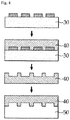
FIG. 4 is a schematic view showing a process of fabricating a 3D pattern mold of a polymer material and transferring the 3D pattern mold to lithium metal according to the present invention. - Hereinafter, the present invention will be described in detail with reference to the accompanying drawings. The present invention is not limited by the following examples. The embodiments according to the present invention can be modified into various other forms, and the scope of the present invention should not be construed as being limited to the embodiments described below. The embodiments of the present invention are provided to more fully describe the present invention to those skilled in the art.
- As shown in
FIG. 2 , a3D pattern puncher 100 according to the present invention includes: amold punch 10 which moves up and down with a mold suited to the size of a unit electrode; a die 14 corresponding to themold punch 10; amold blade 11 disposed at an edge of themold punch 10 to punch alithium metal electrode 13 to become unit electrodes; and a3D pattern 12 located on an inner portion of themold punch 10 contacting the die 14 and formed in a non-bladed portion. - The
mold punch 10 shown inFIG. 2 has themold blade 11 at its edge and the3D pattern 12 formed inside. The die 14 is formed so as to engage with themold blade 11 and the3D pattern 12. Themold blade 11 is shown thick and pointed inFIG. 2 to emphasize the punch function, but actually functions as a thin blade. Thelithium metal electrode 13 is positioned on thedie 14, and themetal punch 10 is lowered and engaged with the die 14 to punch thelithium metal electrode 13 and simultaneously engrave a 3D pattern on the surface. It is preferable that thelithium metal electrode 13 is actually supplied continuously, and in order to emphasize the punching function, inFIG. 2 , an unwinder (not shown) for continuously supplying thelithium metal electrode 13 and a portion where thelithium metal electrode 13 is continually supplied are not shown. - In the present invention, the object of the punching is the
lithium metal electrode 13 having a capacity per unit weight of about 3860 mAh/g, which is very useful as a negative electrode. However, the pure lithium metal has a density of 0.54 g/cm3 and has a problem of continuously reacting with the electrolyte to form dendrites. However, because of its soft nature, plastic processing and punching are easy, and it is easy to engrave 3D patterns on the surface. - The size of the lithium metal unit electrode may vary depending on the size and capacity of the battery to be manufactured. It is also possible to bend the electrode at a certain level because of its easy processing property. Therefore, it can be used for stacked, folded, and stacked-folded type electrode assemblies.
- The
mold punch 10 punches thelithium metal electrode 13 to become unit electrodes through a vertical movement. The vertical movement may be performed by a crank type, a gravity type, a hydraulic type, etc., and is not limited as long as it can apply a constant pressure while moving up and down. Themold punch 10 cuts thelithium metal electrode 13 into unit electrodes by applying a constant pressure to thelithium metal electrode 13 while descending from the top to the bottom with thelithium metal electrode 13 positioned on thedie 14. - The die 14 corresponding to the
mold punch 10 has a size to engage with themold punch 10 so that themold punch 10 is lowered and engaged to punch thelithium metal electrode 13. An unwinder may be further provided on the side of thedie 14. As such, thelithium metal electrode 13 is continually supplied, thelithium metal electrode 13 is punched into unit electrodes in themold punch 10 and thedie 14, then if the mold punch goes upward, as thelithium metal electrode 13 before being punched pushes the punched electrode and is continually supplied, the lithium metal unit electrodes are continually produced. It is preferable that thedie 14 is made of a metal material having a strength greater than that of themold punch 10 since the impact of themold punch 10 should be absorbed for a long time. - The
mold blade 11, which cuts thelithium metal electrode 13 into unit electrodes, is located at the edge of themold punch 10. Themold blade 11 may be attached to the punch with a separate structure, but it is more preferable that themold blade 11 is integrally formed with the mold, because the structure is simplified and it is advantageous in maintenance. Themold punch 10 has a size suitable for the lithium metal unit electrode and themold blade 11 is positioned at the edge thereof to cut thelithium metal electrode 13 into unit electrode sizes. If the suppliedlithium metal electrode 13 is supplied in the longitudinal direction with the same width as the unit electrode, themetal blade 11 is positioned only in the width direction, and if thelithium metal electrode 13 has the same length as the unit electrode and is supplied in the width direction, themold blade 11 is positioned only in the longitudinal direction. If thelithium metal electrode 13 is supplied in a direction inconsistent with the size of the unit electrode in any direction, themold blade 11 should be positioned on all sides of themold punch 10. In consideration of the productivity, it is preferable that the suppliedlithium metal electrode 13 is aligned with the unit electrode in the length or width direction and the number of themold blades 11 is reduced. - A
3D pattern 12 is formed on the inner side of themold punch 10 in contact with thelithium metal electrode 13. When thelithium metal electrode 13 is placed on the die and is punched into unit electrodes as themold punch 10 descends and is engaged with the die 14, the3D pattern 12 formed at the inner side comes into contact with thelithium metal electrode 13 to engrave the 3D pattern on the surface of thelithium metal electrode 13. - The
3D pattern 12 may be embossed or engraved, and if the3D pattern 12 engraved inside thepunch mold punch 10 is embossed, an engraved 3D pattern is engraved on thelithium metal electrode 13, and if the3D pattern 12 engraved inside thepunch mold punch 10 is engraved, embossed 3D patterns are engraved on thelithium metal electrode 13. The3D pattern 12 has a shape of any one of a mesh, a lamellar, an emboss, a linear, a circle, an ellipse, a polygon, and a waveform, and this may be variously selected according to the usage of the battery to be manufactured using the lithium metal electrode and the degree of dendrite growth inhibition to be given to thelithium metal electrode 13. - The depth of the
3D pattern 12 is preferably 10 to 100 µm. The 3D pattern of the same depth is also formed in thelithium metal electrode 13 by the depth of the3D pattern 12 of themold punch 10, and the height of thelithium metal electrode 13 is usually within several hundreds of micrometers. And if the depth is less than 10 µm, the effect of suppressing the growth of dendrite is reduced. If the depth is more than 100 µm, the processability is deteriorated and it is difficult to continually engrave a constant pattern. - The
mold punch 10 of the present invention is either a mold in which a3D pattern 12 mold of a polymer material is attached to a metal mold or a mold in which the mold is integrally made of a polymer material. In the case of a metal mold, themold blade 11 is also integrally made of a metal material, and the3D pattern 12 of a polymer material is attached on the inside of the mold. When the mold is integrally made of a polymer material, themold blade 11 and the3D pattern 12 are integrally made of a polymer material. - In the prior art, the electrode is rolled using the
roller 1 with the 3D pattern engraved. In this case, there are two problems. One is that when the pattern to be engraved is to be replaced, the roller itself needs to be replaced, which is not desirable in terms of cost and time, which leads to poor productivity. Another problem is that the rollers used in the rolling process usually use a metal which is heavy in order to have a certain pressure, which leads to a poor releasing property with lithium metal. When the lithium metal electrode 3 is rolled with the roller, the lithium metal sticks to the roller due to its poor releasing property. And when the lithium metal sticks to the lithium metal continuously during the rolling process, the shape of the later engraved 3D pattern becomes different from the original shape. Therefore, in order to engrave a certain type of 3D pattern, it is necessary to clean the lithium metal sticking to the roller from time to time, which leads to an increase in production cost and time. - The
mold punch 10 of the present invention uses a3D pattern 12 of a polymer material attached to a metal mold so that only the3D pattern 12 mold needs to be replaced when the3D pattern 12 is to be changed, and thus the above problem can be solved. In the prior art, it takes a lot of time and cost because the entire roller needs to be replaced. However, the replacement of the3D pattern 12 according to the present invention requires only a replacement of the3D pattern 12 mold made of a polymer material, and thus the costs and time can be saved. Even if the entire mold is made of a polymer material, the mold itself can be replaced with a mold having another 3D pattern (12), so that replacement of the entire metal roller is simpler and the cost is reduced. - When the mold of the
3D pattern 12 made of the polymer material is attached to the mold or the mold itself is made of a polymer material, the releasability with thelithium metal electrode 13 is improved as compared with the prior art. As the polymer material, polycarbonate, polyurethane acrylate, polyethylene terephthalate, polypropylene, polystyrene, polybutylene terephthalate and the like can be used. Particularly, since polyurethane acrylate and polycarbonate have appropriate hardness and releasability, they may be preferred in that a precise pattern can be engraved on a metal and at the same time they can be reused without being broken even if the process of pressing on the lithium metal is repeated several times. - Even when the entire mold is made of a polymer material and the
mold blade 11 is also made of a polymer material, the lithium metal has a soft nature and can be sufficiently punched because of its good processibility. Unlike the prior art, the3D pattern 12 mold having improved releasability does not need to be cleaned frequently since the lithium metal does not adhere well after the 3D pattern is engraved, and the 3D pattern engraved on thelithium metal electrode 13 can be more uniformly engraved. - The method of forming the 3D pattern on the mold of the polymer material attached to the mold punch of the present invention is not particularly limited and any known method such as photolithography or soft lithography can be used. Examples of the soft lithography method include fine contact printing, decal transfer microlithography, photo-bonding mask method, replica molding, capillary-fine molding method, and the like. In the present invention, The replica molding method is suitable because the process is relatively simple, it is convenient for mass copying of a multidimensional structure and is suitable for mass production at a low cost.
- Replica molding is a replica of original information using a stamp made of flexible polymer. Referring to
FIG. 4 , in order to manufacture the 3D pattern mold of the present invention, asilicon master mold 30 having a desired 3D pattern is prepared, and a polymer precursor 31 such as polyurethane acrylate is poured on the silicon master mold. The polymer is then cured to form apolyurethane acrylate mold 40. - The thus formed
polyurethane acrylate mold 40 is attached to the mold punch, and thelithium metal 50 is placed on the die. When the mold punch is pushed down to be lowered from the top down, the 3D pattern is transferred to the lithium metal. - In order to prevent contamination due to moisture reactivity of the lithium metal and to give more reliable releasability, a hydrophobic material, etc. may be thinly (several nm) coated on a polyurethane acrylate mold by using a spin coating scheme.
- The present invention also provides a method of manufacturing the lithium
metal unit electrode 21 using the3D pattern puncher 100. The method includes positioning thelithium metal electrode 13 on thedie 14; engraving the 3D pattern on the surface of thelithium metal electrode 13 while pushing down themold punch 10 from the top to the bottom; and releasing the lithiummetal unit electrode 21 from the mold by lifting themold punch 10. - The present invention is also characterized in providing a lithium
metal unit electrode 21 manufactured by the above manufacturing method and a secondary battery including the unit electrode.FIG. 3 schematically shows a lithiummetal unit electrode 21 according to the present invention, and shows asquare 3D pattern 22 in an enlarged view. - Since the lithium
metal unit electrode 21 manufactured according to the above method is more uniformly engraved with the 3D pattern, the generation of dendrite on the electrode surface becomes more uniform than when the same size and shape are formed by the conventional art. When the generation of dendrite is made uniform, the lifetime and safety of the electrode are improved. - The secondary battery using the electrode improves the lifetime and safety of the electrode, thereby improving battery life and cycle characteristics.
- Hereinafter, the present invention will be described in more detail through the examples below. However, the following examples are intended to illustrate the present invention and the scope of the present invention is not limited by these examples.
- A metal mold punch having a 3D pattern mold having a cubic 3D pattern of a size of 20 µm x 20 µm x 20 µm (width x breadth x depth) was prepared. The material of the 3D pattern mold was polyurethane acrylate. A lithium metal electrode having a thickness of 100 µm was placed on the die. While pushing down the punching mold from the top down, a 3D pattern was engraved on the surface of the lithium metal electrode and punched out. The punched lithium metal unit electrode was released from the mold, and the mold punch was moved up and down while continuously supplying the lithium metal electrode through the roller-type unwinder on the side of the die, thereby preparing 10 lithium metal unit electrodes.
- A lithium metal unit electrode was prepared in the same manner as in Example 1 except that a 3D pattern mold having a semi-spherical 3D pattern with a diameter of 20 µm was attached.
- The lithium metal unit electrode has been manufactured in the same manner as Example 1 except that the punch mold and 3D pattern integrally use a mold made of polyurethane acrylate.
- The lithium metal unit electrode has been manufactured in the same manner as Example 2 except that the punch mold and 3D pattern integrally use a mold made of polyurethane acrylate.
- A metal roller having a cubic 3D pattern with a size of 20 µm x 20 µm x 20 µm (width x breadth x depth) was prepared. A lithium metal electrode having a thickness of 100 µm was rolled with the roller and a 3D pattern was formed on the surface. A lithium metal electrode having a 3D pattern was cut to a predetermined size to prepare 10 lithium metal unit electrodes.
- A lithium metal unit electrode was prepared in the same manner as in Comparative Example 1 except that a roller having a hemispherical 3D pattern having a diameter of 20 µm was used.
- The lithium metal unit electrodes manufactured in the above embodiments and comparative examples are numbered in the order of manufacturing and the surface of the electrode is observed to show a certain degree of 3D pattern on Table 1. If the square or circular shape of the cross section of the 3D pattern is all correctly etched, and if the depth is constant, it is indicated by O, and if there is any distortion or non-constant depth of the square or circle, it is indicated by X. Also, when the pattern was accurately engraved but the outer cross-section of the punch electrode was not cut smoothly, it was marked separately as Δ beside ○ and X.
[Table 1] Unit electrode no. Example 1 Example 2 Example 3 Example 4 Comparative example 1 Comparative example 2 1 ○ ○ ○ ○ ○ ○ 2 ○ ○ ○ ○ ○ ○ 3 ○ ○ ○ ○ ○ ○ 4 ○ ○ ○ ○ ○ ○ 5 ○ ○ ○ ○ ○ ○ 6 ○ ○ ○ ○ X ○ 7 ○ ○ ○ ○ X ○ 8 ○ ○ ○ ○ X X 9 ○ ○, Δ ○ ○ X X 10 ○, Δ ○, Δ ○ ○ X X - According to Table 1, according to the embodiments of the present invention, there is no deformation of the engraved 3D pattern while engraving a 3D pattern continuously, whereas in the comparative examples, deformation of the engraved 3D pattern occurs when the 3D pattern is continuously engraved.
- While the present invention has been particularly shown and described with reference to exemplary embodiments thereof, it is to be understood that the invention is not limited to the disclosed exemplary embodiments, and various modifications and variations are possible within the scope of the claims.
-
1 : 3D pattern roller 2 : 3D pattern 3 : lithium metal electrode 100 : 3D pattern puncher 10 : mold punch 11 : mold blade 12 : 3D pattern 13 : lithium metal electrode 14 : die 21 : lithium metal unit electrode 22 : 3D pattern 30: silicon master mold 31: polymer precursor 40: polymer mold (soft mold) 50: lithium metal
Claims (10)
- A 3-dimensional (3D) pattern puncher for punching a lithium metal electrode as unit electrodes, the 3D pattern puncher comprising:a mold punch configured to move up and down with a mold suited to a size of the unit electrode;a die corresponding to the mold punch;a mold blade configured to be disposed at an edge of the mold punch and punch the lithium metal electrode as unit electrodes; anda 3D pattern positioned at an inner portion which is in contact with the die of the mold punch and does not have a blade formed thereon.
- The 3D pattern puncher of claim 1, wherein the mold punch is any one of a mold made by sticking a 3D pattern mold made of a polymer material to a metal mold and a mold integrally made of a polymer material.
- The 3D pattern puncher of claim 2, wherein the polymer material is any one of polycarbonate, polyurethane acrylate, polyethylene terephthalate, polypropylene, polystyrene, and polybutylene terephthalate.
- The 3D pattern puncher of claim 1, wherein a depth of the 3D pattern is about 10 µm to about 100 µm.
- The 3D pattern puncher of claim 1, wherein the 3D pattern is engraved in one of an embossed shape or an engraved shape.
- The 3D pattern puncher of claim 1, wherein the 3D pattern has one of a mesh shape, a lamellar shape, an emboss shape, a linear shape, a circular shape, an elliptical shape, a polygonal shape, and a waveform shape.
- The 3D pattern puncher of claim 1, further comprising a roller-shaped unwinder for continuously supplying a lithium metal electrode before being punched to a side surface of the die.
- A method for manufacturing a lithium metal unit electrode using the 3D pattern puncher according to claim 1, the method comprising:positioning the lithium metal unit at a die;pushing a mold punch down and engraving 3D patterns on the lithium metal electrode; andreleasing lithium metal unit electrodes by raising the mold punch.
- A lithium metal unit electrode produced by the method according to claim 8.
- A secondary battery comprising the lithium metal unit electrode according to claim 9.
Applications Claiming Priority (2)
| Application Number | Priority Date | Filing Date | Title |
|---|---|---|---|
| KR1020170086896A KR102246631B1 (en) | 2017-07-10 | 2017-07-10 | 3D Pattern Diecutter for lithium metal electrode |
| PCT/KR2018/007373 WO2019013477A2 (en) | 2017-07-10 | 2018-06-29 | 3d pattern cutting machine for lithium metal electrode |
Publications (3)
| Publication Number | Publication Date |
|---|---|
| EP3547415A2 true EP3547415A2 (en) | 2019-10-02 |
| EP3547415A4 EP3547415A4 (en) | 2020-03-04 |
| EP3547415B1 EP3547415B1 (en) | 2023-01-18 |
Family
ID=65002086
Family Applications (1)
| Application Number | Title | Priority Date | Filing Date |
|---|---|---|---|
| EP18832390.1A Active EP3547415B1 (en) | 2017-07-10 | 2018-06-29 | 3d pattern cutting machine for lithium metal electrode |
Country Status (6)
| Country | Link |
|---|---|
| US (1) | US11005092B2 (en) |
| EP (1) | EP3547415B1 (en) |
| JP (1) | JP7037018B2 (en) |
| KR (1) | KR102246631B1 (en) |
| CN (1) | CN110140240B (en) |
| WO (1) | WO2019013477A2 (en) |
Families Citing this family (5)
| Publication number | Priority date | Publication date | Assignee | Title |
|---|---|---|---|---|
| KR102341464B1 (en) * | 2018-05-04 | 2021-12-22 | 주식회사 엘지에너지솔루션 | Cutting device and method for electrode sheet |
| KR102765440B1 (en) * | 2019-01-30 | 2025-02-12 | 삼성에스디아이 주식회사 | Secondary battery |
| KR102803275B1 (en) * | 2019-04-25 | 2025-05-07 | 주식회사 엘지에너지솔루션 | Electrode notching equipment for rechargeable battery, electrode manufactured from thereof and rechargeable battery |
| CN112186257B (en) * | 2020-08-28 | 2021-12-28 | 西安交通大学 | Three-dimensional lithium battery preparation method based on direct-writing forming 3D printing technology |
| EP4628267A1 (en) | 2024-04-03 | 2025-10-08 | Leef Blattwerk GmbH | Method for producing a recess in a packaging part from a leaf material of a plant |
Family Cites Families (46)
| Publication number | Priority date | Publication date | Assignee | Title |
|---|---|---|---|---|
| JPS4844710B1 (en) | 1969-12-15 | 1973-12-26 | ||
| JPS5591622A (en) * | 1978-12-29 | 1980-07-11 | Matsushita Electric Works Ltd | Forming method and device for tile having embossed figure |
| JPH0789484B2 (en) | 1991-05-28 | 1995-09-27 | 松下電器産業株式会社 | Method for manufacturing negative electrode of non-aqueous electrolyte battery |
| JP3168783B2 (en) | 1993-09-21 | 2001-05-21 | 松下電器産業株式会社 | Negative electrode plate for non-aqueous electrolyte secondary battery and method for producing the same |
| JPH07272726A (en) * | 1994-03-30 | 1995-10-20 | Yuasa Corp | Manufacture of metallic current collector |
| JP2002237560A (en) | 2000-12-05 | 2002-08-23 | Ueno Seiki Kk | Lead electrode cutter for electronic component |
| JP2003001595A (en) * | 2001-06-26 | 2003-01-08 | Masatsugu Tomita | Trimming die and die-cutting method |
| US7011004B2 (en) * | 2001-07-06 | 2006-03-14 | Honda Giken Kogyo Kabushiki Kaisha | Trimming apparatus and method for fuel cell membrane/electrode coupling and transporting apparatus |
| JP2003059486A (en) * | 2001-08-10 | 2003-02-28 | Matsushita Electric Ind Co Ltd | Stacked battery and method of manufacturing the same |
| KR100416321B1 (en) * | 2001-08-20 | 2004-01-31 | 제노에너지(주) | Forming Method of Anode for Li Battery using Li Powder |
| US6869727B2 (en) * | 2002-09-20 | 2005-03-22 | Eveready Battery Company, Inc. | Battery with high electrode interfacial surface area |
| KR100582557B1 (en) | 2004-11-25 | 2006-05-22 | 한국전자통신연구원 | A negative electrode for a lithium metal polymer secondary battery comprising a surface-patterned negative electrode current collector and a manufacturing method thereof |
| FI20055022L (en) * | 2005-01-17 | 2006-07-18 | Avantone Oy | Method and apparatus for die-cutting and die-cutting machine |
| JP4844710B2 (en) | 2005-03-28 | 2011-12-28 | セイコーエプソン株式会社 | Filter manufacturing method, filter, and liquid jet head |
| WO2006131153A1 (en) * | 2005-06-10 | 2006-12-14 | Obducat Ab | Pattern replication with intermediate stamp |
| CN101145608B (en) | 2006-09-14 | 2010-06-16 | 松下电器产业株式会社 | Negative electrode for lithium ion secondary battery and lithium ion secondary battery using the same |
| JP2008270153A (en) | 2006-11-15 | 2008-11-06 | Matsushita Electric Ind Co Ltd | Non-aqueous electrolyte secondary battery current collector manufacturing method, non-aqueous electrolyte secondary battery electrode manufacturing method, and non-aqueous electrolyte secondary battery |
| US20080248386A1 (en) * | 2007-04-05 | 2008-10-09 | Obrovac Mark N | Electrodes with raised patterns |
| US20090075142A1 (en) * | 2007-09-13 | 2009-03-19 | The Regents Of University Of Michigan | Nanoimprinted electrodes for fuel cells |
| KR20090118588A (en) | 2008-05-14 | 2009-11-18 | 한국전기연구원 | Method for manufacturing electrode for energy storage device |
| WO2011037285A1 (en) * | 2009-09-24 | 2011-03-31 | Hwang Choon Seob | Electrode production method |
| US20120003572A1 (en) * | 2010-02-10 | 2012-01-05 | Jun Matsumura | Manufacturing method and manufacturing apparatus for catalyst-coated membrane assembly |
| JP5383571B2 (en) * | 2010-03-26 | 2014-01-08 | 三菱重工業株式会社 | Electrode plate manufacturing equipment |
| JP5461267B2 (en) * | 2010-03-26 | 2014-04-02 | 三菱重工業株式会社 | Electrode plate manufacturing apparatus and electrode plate manufacturing method |
| KR101064821B1 (en) | 2011-03-14 | 2011-09-14 | 윤광원 | Cutting mold and its manufacturing method |
| JP6075961B2 (en) | 2011-04-07 | 2017-02-08 | 日産自動車株式会社 | Battery electrode manufacturing apparatus and method |
| US20140197801A1 (en) * | 2011-05-20 | 2014-07-17 | The Board Of Trustees Of The University Of Illinois | Silicon-based electrode for a lithium-ion cell |
| JP5916485B2 (en) * | 2012-04-02 | 2016-05-11 | 東京応化工業株式会社 | Negative electrode for lithium ion secondary battery, lithium ion secondary battery, and method for producing negative electrode for lithium ion secondary battery |
| US10084168B2 (en) | 2012-10-09 | 2018-09-25 | Johnson Battery Technologies, Inc. | Solid-state battery separators and methods of fabrication |
| JP2014175155A (en) | 2013-03-08 | 2014-09-22 | Toppan Printing Co Ltd | Electrode for nonaqueous electrolyte secondary battery, method for manufacturing the same, and nonaqueous electrolyte secondary battery |
| JP2015138619A (en) | 2014-01-21 | 2015-07-30 | パナソニックIpマネジメント株式会社 | Method for manufacturing negative electrode of nonaqueous electrolyte secondary battery, and device for manufacturing negative electrode of nonaqueous electrolyte secondary battery |
| KR101618428B1 (en) | 2014-02-07 | 2016-05-09 | 고려대학교 산학협력단 | Electrode structure for a lithium-sulfur secondary cell and method of manufacturing the same |
| KR101579053B1 (en) * | 2014-02-28 | 2015-12-21 | 한국기계연구원 | A Manufacturing Method of metal mesh electrode and a Organic Electroluminescence Display Device comprising the metal mesh electrode |
| CN105304856A (en) | 2014-08-01 | 2016-02-03 | 中国电子科技集团公司第十八研究所 | Preparation method of negative plate of primary lithium battery |
| KR101984719B1 (en) * | 2014-10-23 | 2019-05-31 | 주식회사 엘지화학 | Li metal electrode with multi-layer and forming method thereof |
| CN104668331B (en) * | 2014-12-29 | 2016-11-23 | 东莞市鸿宝锂电科技有限公司 | Lithium battery pole slice punching and cutting forming machine and die-cut micromatic setting thereof |
| KR101558538B1 (en) * | 2015-04-17 | 2015-10-12 | (주)태린 | Apparatus and method for forming metal wire mesh filter |
| KR102003297B1 (en) * | 2015-07-29 | 2019-07-24 | 주식회사 엘지화학 | Patterning Lithium Electrode and Method for Manufacturing thereof and Lithium Secondary Battery using the same |
| PL3349273T3 (en) * | 2015-12-15 | 2019-12-31 | Lg Chem, Ltd. | Electrode for electrochemical device and electrochemical device including the same |
| CN105345889B (en) * | 2015-12-18 | 2017-11-10 | 深圳市汇鑫垒刀模科技有限公司 | Carry the cross cutting band belling cutting die of pressure adjusting function |
| KR101794187B1 (en) | 2016-01-19 | 2017-11-06 | 한국인터넷진흥원 | Method and incident management system, and computer-readable recording medium |
| CN205587509U (en) * | 2016-03-09 | 2016-09-21 | 江苏东顺新能源科技有限公司 | Die -cut mechanism of storage battery plant bars |
| KR101737790B1 (en) * | 2016-07-15 | 2017-05-19 | 안혁 | A Press Mold Device of manufacturing cell ploeplate for hybrid electric vehicle |
| CN106207195B (en) * | 2016-09-20 | 2019-06-14 | 广东国光电子有限公司 | A laminated flexible battery and its manufacturing method |
| WO2019039328A1 (en) * | 2017-08-21 | 2019-02-28 | 株式会社村田製作所 | Cutting device |
| JP7096717B2 (en) * | 2018-07-04 | 2022-07-06 | 東レエンジニアリング株式会社 | Electrode sheet manufacturing method and electrode sheet manufacturing equipment |
-
2017
- 2017-07-10 KR KR1020170086896A patent/KR102246631B1/en active Active
-
2018
- 2018-06-29 US US16/346,948 patent/US11005092B2/en active Active
- 2018-06-29 CN CN201880005623.4A patent/CN110140240B/en active Active
- 2018-06-29 JP JP2019537227A patent/JP7037018B2/en active Active
- 2018-06-29 EP EP18832390.1A patent/EP3547415B1/en active Active
- 2018-06-29 WO PCT/KR2018/007373 patent/WO2019013477A2/en not_active Ceased
Also Published As
| Publication number | Publication date |
|---|---|
| CN110140240B (en) | 2022-05-27 |
| JP7037018B2 (en) | 2022-03-16 |
| CN110140240A (en) | 2019-08-16 |
| US20200058931A1 (en) | 2020-02-20 |
| EP3547415A4 (en) | 2020-03-04 |
| WO2019013477A2 (en) | 2019-01-17 |
| EP3547415B1 (en) | 2023-01-18 |
| WO2019013477A3 (en) | 2019-04-11 |
| US11005092B2 (en) | 2021-05-11 |
| KR102246631B1 (en) | 2021-04-30 |
| KR20190006210A (en) | 2019-01-18 |
| JP2020514981A (en) | 2020-05-21 |
Similar Documents
| Publication | Publication Date | Title |
|---|---|---|
| EP3547415B1 (en) | 3d pattern cutting machine for lithium metal electrode | |
| EP2783405B1 (en) | Embossed separators, batteries and methods | |
| JP2017084793A (en) | Method to fabricate variation in porosity of lithium ion battery electrode film | |
| US20100112452A1 (en) | Battery current collector, method for producing the same, and non-aqueous secondary battery | |
| CN101512800A (en) | Collector for nonaqueous secondary battery, electrode plate for nonaqueous secondary battery using same, and nonaqueous secondary battery | |
| US20180337392A1 (en) | Electrode, method for manufacturing the electrode, and roller for manufacturing the electrode | |
| CN108028351B (en) | Secondary battery electrode manufacturing apparatus including electrode mixture layer forming mold | |
| JP2010225432A (en) | Solid secondary battery, method for producing solid secondary battery | |
| KR101685559B1 (en) | Method for manufacturing high density electrode for electric double layer capacitor | |
| EP4181232B1 (en) | Lithium foil lamination apparatus for anode material of li-metal battery | |
| US6454978B1 (en) | Process for making fuel cell plates | |
| KR101847818B1 (en) | Method for forming pattern of metal electrode and roller therefor | |
| HK1049916A1 (en) | Method for producing electrode for alkali batteries | |
| CN215496788U (en) | Pattern pole piece structure and pole piece pattern tool of cylindrical lithium battery | |
| US20030107147A1 (en) | Process and apparatus for making fuel cell plates | |
| JPH09293500A (en) | Manufacture of electrode plate for use in storage battery | |
| JP4555222B2 (en) | Electrode, electrode manufacturing method, and bipolar battery | |
| JP2005166914A (en) | Manufacturing method of solar cell | |
| JP5369988B2 (en) | Method and apparatus for manufacturing electrode current collector of power storage device | |
| KR20210066529A (en) | Manufacturing method an anode for lithium metal battery | |
| WO2001098047A1 (en) | A process and apparatus for making fuel cell plates | |
| US20020108510A1 (en) | Apparatus for making fuel cell plates | |
| JP2006252805A (en) | Method for producing electrode plate for alkaline storage battery | |
| EP4563260A1 (en) | Stamp punching oil applicator and method for manufacturing electrode plate for secondary battery using the same | |
| WO2025146605A1 (en) | A device to fabricate three-dimensional electrode |
Legal Events
| Date | Code | Title | Description |
|---|---|---|---|
| STAA | Information on the status of an ep patent application or granted ep patent |
Free format text: STATUS: THE INTERNATIONAL PUBLICATION HAS BEEN MADE |
|
| PUAI | Public reference made under article 153(3) epc to a published international application that has entered the european phase |
Free format text: ORIGINAL CODE: 0009012 |
|
| STAA | Information on the status of an ep patent application or granted ep patent |
Free format text: STATUS: REQUEST FOR EXAMINATION WAS MADE |
|
| 17P | Request for examination filed |
Effective date: 20190626 |
|
| AK | Designated contracting states |
Kind code of ref document: A2 Designated state(s): AL AT BE BG CH CY CZ DE DK EE ES FI FR GB GR HR HU IE IS IT LI LT LU LV MC MK MT NL NO PL PT RO RS SE SI SK SM TR |
|
| AX | Request for extension of the european patent |
Extension state: BA ME |
|
| A4 | Supplementary search report drawn up and despatched |
Effective date: 20200203 |
|
| RIC1 | Information provided on ipc code assigned before grant |
Ipc: B21D 28/14 20060101ALI20200128BHEP Ipc: H01M 4/1395 20100101AFI20200128BHEP Ipc: B21D 22/04 20060101ALI20200128BHEP Ipc: B26F 1/40 20060101ALI20200128BHEP Ipc: H01M 10/052 20100101ALI20200128BHEP Ipc: H01M 4/04 20060101ALI20200128BHEP |
|
| DAV | Request for validation of the european patent (deleted) | ||
| DAX | Request for extension of the european patent (deleted) | ||
| STAA | Information on the status of an ep patent application or granted ep patent |
Free format text: STATUS: EXAMINATION IS IN PROGRESS |
|
| 17Q | First examination report despatched |
Effective date: 20210111 |
|
| RAP1 | Party data changed (applicant data changed or rights of an application transferred) |
Owner name: LG ENERGY SOLUTION LTD. |
|
| RAP3 | Party data changed (applicant data changed or rights of an application transferred) |
Owner name: LG ENERGY SOLUTION, LTD. |
|
| GRAP | Despatch of communication of intention to grant a patent |
Free format text: ORIGINAL CODE: EPIDOSNIGR1 |
|
| STAA | Information on the status of an ep patent application or granted ep patent |
Free format text: STATUS: GRANT OF PATENT IS INTENDED |
|
| INTG | Intention to grant announced |
Effective date: 20221011 |
|
| GRAS | Grant fee paid |
Free format text: ORIGINAL CODE: EPIDOSNIGR3 |
|
| GRAA | (expected) grant |
Free format text: ORIGINAL CODE: 0009210 |
|
| STAA | Information on the status of an ep patent application or granted ep patent |
Free format text: STATUS: THE PATENT HAS BEEN GRANTED |
|
| AK | Designated contracting states |
Kind code of ref document: B1 Designated state(s): AL AT BE BG CH CY CZ DE DK EE ES FI FR GB GR HR HU IE IS IT LI LT LU LV MC MK MT NL NO PL PT RO RS SE SI SK SM TR |
|
| REG | Reference to a national code |
Ref country code: GB Ref legal event code: FG4D |
|
| REG | Reference to a national code |
Ref country code: CH Ref legal event code: EP |
|
| REG | Reference to a national code |
Ref country code: DE Ref legal event code: R096 Ref document number: 602018045582 Country of ref document: DE |
|
| REG | Reference to a national code |
Ref country code: AT Ref legal event code: REF Ref document number: 1545171 Country of ref document: AT Kind code of ref document: T Effective date: 20230215 Ref country code: IE Ref legal event code: FG4D |
|
| REG | Reference to a national code |
Ref country code: LT Ref legal event code: MG9D |
|
| REG | Reference to a national code |
Ref country code: NL Ref legal event code: MP Effective date: 20230118 |
|
| P01 | Opt-out of the competence of the unified patent court (upc) registered |
Effective date: 20230408 |
|
| REG | Reference to a national code |
Ref country code: AT Ref legal event code: MK05 Ref document number: 1545171 Country of ref document: AT Kind code of ref document: T Effective date: 20230118 |
|
| PG25 | Lapsed in a contracting state [announced via postgrant information from national office to epo] |
Ref country code: NL Free format text: LAPSE BECAUSE OF FAILURE TO SUBMIT A TRANSLATION OF THE DESCRIPTION OR TO PAY THE FEE WITHIN THE PRESCRIBED TIME-LIMIT Effective date: 20230118 |
|
| PG25 | Lapsed in a contracting state [announced via postgrant information from national office to epo] |
Ref country code: RS Free format text: LAPSE BECAUSE OF FAILURE TO SUBMIT A TRANSLATION OF THE DESCRIPTION OR TO PAY THE FEE WITHIN THE PRESCRIBED TIME-LIMIT Effective date: 20230118 Ref country code: PT Free format text: LAPSE BECAUSE OF FAILURE TO SUBMIT A TRANSLATION OF THE DESCRIPTION OR TO PAY THE FEE WITHIN THE PRESCRIBED TIME-LIMIT Effective date: 20230518 Ref country code: NO Free format text: LAPSE BECAUSE OF FAILURE TO SUBMIT A TRANSLATION OF THE DESCRIPTION OR TO PAY THE FEE WITHIN THE PRESCRIBED TIME-LIMIT Effective date: 20230418 Ref country code: LV Free format text: LAPSE BECAUSE OF FAILURE TO SUBMIT A TRANSLATION OF THE DESCRIPTION OR TO PAY THE FEE WITHIN THE PRESCRIBED TIME-LIMIT Effective date: 20230118 Ref country code: LT Free format text: LAPSE BECAUSE OF FAILURE TO SUBMIT A TRANSLATION OF THE DESCRIPTION OR TO PAY THE FEE WITHIN THE PRESCRIBED TIME-LIMIT Effective date: 20230118 Ref country code: HR Free format text: LAPSE BECAUSE OF FAILURE TO SUBMIT A TRANSLATION OF THE DESCRIPTION OR TO PAY THE FEE WITHIN THE PRESCRIBED TIME-LIMIT Effective date: 20230118 Ref country code: ES Free format text: LAPSE BECAUSE OF FAILURE TO SUBMIT A TRANSLATION OF THE DESCRIPTION OR TO PAY THE FEE WITHIN THE PRESCRIBED TIME-LIMIT Effective date: 20230118 Ref country code: AT Free format text: LAPSE BECAUSE OF FAILURE TO SUBMIT A TRANSLATION OF THE DESCRIPTION OR TO PAY THE FEE WITHIN THE PRESCRIBED TIME-LIMIT Effective date: 20230118 |
|
| PG25 | Lapsed in a contracting state [announced via postgrant information from national office to epo] |
Ref country code: SE Free format text: LAPSE BECAUSE OF FAILURE TO SUBMIT A TRANSLATION OF THE DESCRIPTION OR TO PAY THE FEE WITHIN THE PRESCRIBED TIME-LIMIT Effective date: 20230118 Ref country code: PL Free format text: LAPSE BECAUSE OF FAILURE TO SUBMIT A TRANSLATION OF THE DESCRIPTION OR TO PAY THE FEE WITHIN THE PRESCRIBED TIME-LIMIT Effective date: 20230118 Ref country code: IS Free format text: LAPSE BECAUSE OF FAILURE TO SUBMIT A TRANSLATION OF THE DESCRIPTION OR TO PAY THE FEE WITHIN THE PRESCRIBED TIME-LIMIT Effective date: 20230518 Ref country code: GR Free format text: LAPSE BECAUSE OF FAILURE TO SUBMIT A TRANSLATION OF THE DESCRIPTION OR TO PAY THE FEE WITHIN THE PRESCRIBED TIME-LIMIT Effective date: 20230419 Ref country code: FI Free format text: LAPSE BECAUSE OF FAILURE TO SUBMIT A TRANSLATION OF THE DESCRIPTION OR TO PAY THE FEE WITHIN THE PRESCRIBED TIME-LIMIT Effective date: 20230118 |
|
| REG | Reference to a national code |
Ref country code: DE Ref legal event code: R097 Ref document number: 602018045582 Country of ref document: DE |
|
| PG25 | Lapsed in a contracting state [announced via postgrant information from national office to epo] |
Ref country code: SM Free format text: LAPSE BECAUSE OF FAILURE TO SUBMIT A TRANSLATION OF THE DESCRIPTION OR TO PAY THE FEE WITHIN THE PRESCRIBED TIME-LIMIT Effective date: 20230118 Ref country code: RO Free format text: LAPSE BECAUSE OF FAILURE TO SUBMIT A TRANSLATION OF THE DESCRIPTION OR TO PAY THE FEE WITHIN THE PRESCRIBED TIME-LIMIT Effective date: 20230118 Ref country code: EE Free format text: LAPSE BECAUSE OF FAILURE TO SUBMIT A TRANSLATION OF THE DESCRIPTION OR TO PAY THE FEE WITHIN THE PRESCRIBED TIME-LIMIT Effective date: 20230118 Ref country code: DK Free format text: LAPSE BECAUSE OF FAILURE TO SUBMIT A TRANSLATION OF THE DESCRIPTION OR TO PAY THE FEE WITHIN THE PRESCRIBED TIME-LIMIT Effective date: 20230118 Ref country code: CZ Free format text: LAPSE BECAUSE OF FAILURE TO SUBMIT A TRANSLATION OF THE DESCRIPTION OR TO PAY THE FEE WITHIN THE PRESCRIBED TIME-LIMIT Effective date: 20230118 |
|
| PLBE | No opposition filed within time limit |
Free format text: ORIGINAL CODE: 0009261 |
|
| STAA | Information on the status of an ep patent application or granted ep patent |
Free format text: STATUS: NO OPPOSITION FILED WITHIN TIME LIMIT |
|
| PG25 | Lapsed in a contracting state [announced via postgrant information from national office to epo] |
Ref country code: SK Free format text: LAPSE BECAUSE OF FAILURE TO SUBMIT A TRANSLATION OF THE DESCRIPTION OR TO PAY THE FEE WITHIN THE PRESCRIBED TIME-LIMIT Effective date: 20230118 |
|
| 26N | No opposition filed |
Effective date: 20231019 |
|
| PG25 | Lapsed in a contracting state [announced via postgrant information from national office to epo] |
Ref country code: MC Free format text: LAPSE BECAUSE OF FAILURE TO SUBMIT A TRANSLATION OF THE DESCRIPTION OR TO PAY THE FEE WITHIN THE PRESCRIBED TIME-LIMIT Effective date: 20230118 |
|
| PG25 | Lapsed in a contracting state [announced via postgrant information from national office to epo] |
Ref country code: SI Free format text: LAPSE BECAUSE OF FAILURE TO SUBMIT A TRANSLATION OF THE DESCRIPTION OR TO PAY THE FEE WITHIN THE PRESCRIBED TIME-LIMIT Effective date: 20230118 Ref country code: MC Free format text: LAPSE BECAUSE OF FAILURE TO SUBMIT A TRANSLATION OF THE DESCRIPTION OR TO PAY THE FEE WITHIN THE PRESCRIBED TIME-LIMIT Effective date: 20230118 |
|
| REG | Reference to a national code |
Ref country code: CH Ref legal event code: PL |
|
| REG | Reference to a national code |
Ref country code: BE Ref legal event code: MM Effective date: 20230630 |
|
| PG25 | Lapsed in a contracting state [announced via postgrant information from national office to epo] |
Ref country code: LU Free format text: LAPSE BECAUSE OF NON-PAYMENT OF DUE FEES Effective date: 20230629 |
|
| PG25 | Lapsed in a contracting state [announced via postgrant information from national office to epo] |
Ref country code: LU Free format text: LAPSE BECAUSE OF NON-PAYMENT OF DUE FEES Effective date: 20230629 |
|
| PG25 | Lapsed in a contracting state [announced via postgrant information from national office to epo] |
Ref country code: IE Free format text: LAPSE BECAUSE OF NON-PAYMENT OF DUE FEES Effective date: 20230629 |
|
| PG25 | Lapsed in a contracting state [announced via postgrant information from national office to epo] |
Ref country code: IE Free format text: LAPSE BECAUSE OF NON-PAYMENT OF DUE FEES Effective date: 20230629 Ref country code: CH Free format text: LAPSE BECAUSE OF NON-PAYMENT OF DUE FEES Effective date: 20230630 |
|
| PG25 | Lapsed in a contracting state [announced via postgrant information from national office to epo] |
Ref country code: IT Free format text: LAPSE BECAUSE OF FAILURE TO SUBMIT A TRANSLATION OF THE DESCRIPTION OR TO PAY THE FEE WITHIN THE PRESCRIBED TIME-LIMIT Effective date: 20230118 Ref country code: BE Free format text: LAPSE BECAUSE OF NON-PAYMENT OF DUE FEES Effective date: 20230630 |
|
| PG25 | Lapsed in a contracting state [announced via postgrant information from national office to epo] |
Ref country code: BG Free format text: LAPSE BECAUSE OF FAILURE TO SUBMIT A TRANSLATION OF THE DESCRIPTION OR TO PAY THE FEE WITHIN THE PRESCRIBED TIME-LIMIT Effective date: 20230118 |
|
| PG25 | Lapsed in a contracting state [announced via postgrant information from national office to epo] |
Ref country code: BG Free format text: LAPSE BECAUSE OF FAILURE TO SUBMIT A TRANSLATION OF THE DESCRIPTION OR TO PAY THE FEE WITHIN THE PRESCRIBED TIME-LIMIT Effective date: 20230118 |
|
| PGFP | Annual fee paid to national office [announced via postgrant information from national office to epo] |
Ref country code: DE Payment date: 20250520 Year of fee payment: 8 |
|
| PGFP | Annual fee paid to national office [announced via postgrant information from national office to epo] |
Ref country code: GB Payment date: 20250520 Year of fee payment: 8 |
|
| PGFP | Annual fee paid to national office [announced via postgrant information from national office to epo] |
Ref country code: FR Payment date: 20250521 Year of fee payment: 8 |
|
| PG25 | Lapsed in a contracting state [announced via postgrant information from national office to epo] |
Ref country code: CY Free format text: LAPSE BECAUSE OF FAILURE TO SUBMIT A TRANSLATION OF THE DESCRIPTION OR TO PAY THE FEE WITHIN THE PRESCRIBED TIME-LIMIT; INVALID AB INITIO Effective date: 20180629 |
|
| PG25 | Lapsed in a contracting state [announced via postgrant information from national office to epo] |
Ref country code: HU Free format text: LAPSE BECAUSE OF FAILURE TO SUBMIT A TRANSLATION OF THE DESCRIPTION OR TO PAY THE FEE WITHIN THE PRESCRIBED TIME-LIMIT; INVALID AB INITIO Effective date: 20180629 |
|
| PG25 | Lapsed in a contracting state [announced via postgrant information from national office to epo] |
Ref country code: TR Free format text: LAPSE BECAUSE OF FAILURE TO SUBMIT A TRANSLATION OF THE DESCRIPTION OR TO PAY THE FEE WITHIN THE PRESCRIBED TIME-LIMIT Effective date: 20230118 |