EP3547345B1 - Fehlerstromschutzvorrichtung und auslöser - Google Patents
Fehlerstromschutzvorrichtung und auslöser Download PDFInfo
- Publication number
- EP3547345B1 EP3547345B1 EP19164907.8A EP19164907A EP3547345B1 EP 3547345 B1 EP3547345 B1 EP 3547345B1 EP 19164907 A EP19164907 A EP 19164907A EP 3547345 B1 EP3547345 B1 EP 3547345B1
- Authority
- EP
- European Patent Office
- Prior art keywords
- residual
- protection device
- current protection
- energy storage
- rack
- Prior art date
- Legal status (The legal status is an assumption and is not a legal conclusion. Google has not performed a legal analysis and makes no representation as to the accuracy of the status listed.)
- Active
Links
Images





Classifications
-
- H—ELECTRICITY
- H01—ELECTRIC ELEMENTS
- H01H—ELECTRIC SWITCHES; RELAYS; SELECTORS; EMERGENCY PROTECTIVE DEVICES
- H01H71/00—Details of the protective switches or relays covered by groups H01H73/00 - H01H83/00
- H01H71/10—Operating or release mechanisms
- H01H71/12—Automatic release mechanisms with or without manual release
- H01H71/128—Manual release or trip mechanisms, e.g. for test purposes
-
- H—ELECTRICITY
- H01—ELECTRIC ELEMENTS
- H01H—ELECTRIC SWITCHES; RELAYS; SELECTORS; EMERGENCY PROTECTIVE DEVICES
- H01H71/00—Details of the protective switches or relays covered by groups H01H73/00 - H01H83/00
- H01H71/10—Operating or release mechanisms
- H01H71/12—Automatic release mechanisms with or without manual release
- H01H71/123—Automatic release mechanisms with or without manual release using a solid-state trip unit
- H01H71/125—Automatic release mechanisms with or without manual release using a solid-state trip unit characterised by sensing elements, e.g. current transformers
-
- H—ELECTRICITY
- H01—ELECTRIC ELEMENTS
- H01H—ELECTRIC SWITCHES; RELAYS; SELECTORS; EMERGENCY PROTECTIVE DEVICES
- H01H71/00—Details of the protective switches or relays covered by groups H01H73/00 - H01H83/00
- H01H71/10—Operating or release mechanisms
- H01H71/50—Manual reset mechanisms which may be also used for manual release
- H01H71/58—Manual reset mechanisms which may be also used for manual release actuated by push-button, pull-knob, or slide
-
- H—ELECTRICITY
- H01—ELECTRIC ELEMENTS
- H01H—ELECTRIC SWITCHES; RELAYS; SELECTORS; EMERGENCY PROTECTIVE DEVICES
- H01H71/00—Details of the protective switches or relays covered by groups H01H73/00 - H01H83/00
- H01H71/10—Operating or release mechanisms
- H01H71/1009—Interconnected mechanisms
-
- H—ELECTRICITY
- H01—ELECTRIC ELEMENTS
- H01H—ELECTRIC SWITCHES; RELAYS; SELECTORS; EMERGENCY PROTECTIVE DEVICES
- H01H83/00—Protective switches, e.g. circuit-breaking switches, or protective relays operated by abnormal electrical conditions otherwise than solely by excess current
- H01H83/14—Protective switches, e.g. circuit-breaking switches, or protective relays operated by abnormal electrical conditions otherwise than solely by excess current operated by imbalance of two or more currents or voltages, e.g. for differential protection
- H01H83/144—Protective switches, e.g. circuit-breaking switches, or protective relays operated by abnormal electrical conditions otherwise than solely by excess current operated by imbalance of two or more currents or voltages, e.g. for differential protection with differential transformer
Definitions
- the present application relates to the field of circuit breakers, and more specifically, to a residual current protection device and a tripper.
- Circuit breakers are widely applied to middle and low voltage circuits to distribute power and protect lines, power sources and electric equipment.
- a tripper is assembled on a circuit breaker, and the tripper is used to perform protection functions, such as overload protection, short circuit protection, delay protection and leakage protection.
- the circuit breaker is further configured with a residual-current protection device.
- Residual current which is also called excess current, after-current or leakage current, refers to a current with a nonzero sum of all phase current vectors in a low-voltage distribution line.
- the residual-current protection device is a protector that switches on the electric connection from a supply line to a load under a normal operating condition, triggers a contact action of the circuit breaker and thus breaks the supply line when the residual current on the supply line exceeds a predetermined scope under a specified condition.
- the residual-current protection device is intended to accomplish a residual current protection function and thereby guarantee the security of people and systems.
- the residual-current protection device may be used in cooperation with a moulded case circuit breaker so as to prevent the residual current from causing electric shock and fire accidents.
- the publication CN 203 071 024 U describes a residual-current protection device according to the preamble of claim 1.
- the residual-current protection device generally trips the circuit breaker by triggering a flux transformer that receives a residual current signal so that an armature of the flux transformer pops out to directly hit a trip lever of the circuit breaker.
- the residual-current protection device needs to provide a larger trip force. Therefore, impact force of the flux transformer has to be increased, accordingly, the power and volume of the flux transformer need to be risen, and requirements on the product space and design of a control circuit are also enhanced. This can barely meet the design requirement as miniaturization.
- the present application provides a residual-current protection device and a tripper that can at least partly overcome or relieve one or more technical problems in the prior art.
- the residual-current protection device includes: a flux transformer receiving a residual-current signal; a tripping output element outputting ON/OFF signals; an energy storage mechanism suitable to switch between an energy storage state and an energy release state, the energy storage mechanism having a locking unit that locks the energy storage mechanism in the energy storage state; and a transmission mechanism driven by the flux transformer, which drives the tripping output element to move and drives the state of the energy storage mechanism to switch, the transmission mechanism comprising a first rack cooperating with the locking unit, a second rack driving the tripping output element, and a reduction gear, having a big gear end engaged with the first rack and a small gear end engaged with the second rack.
- gear rack transmission mechanism of the residual-current protection device By means of the gear rack transmission mechanism of the residual-current protection device, reduction transmission may be obtained, driving force needed by energy storage may be reduced, and thus design requirements as high transmission efficiency, easy processing and assembly as well as low costs are satisfied.
- the transmission mechanism includes a button and a slot body for the button to slide.
- the locking unit includes a U-shaped swing bar arranged within the slot body and a locking member suitable to change the shape of the slot body so as to control swing amplitude of the swing bar when the button is sliding.
- the locking member includes a stepped structure arranged on the first rack and a wedge linked with the button via a reset spring, step faces of the stepped structure being provided facing with a wedge face of the wedge.
- the button and an end face of the first rack opposite thereto have overlapped portions.
- the button when being pressed, may drive the first rack to move together, so that a second rack is driven via a reduction gear to move so as to enter energy storage state.
- the button includes an integrally extended push rod that triggers the flux transformer to reset. This design makes it possible for the button and the flux transformer to be mutually triggered, which simplifies the structure.
- the second rack is linked with a tripping output element via an energy storage spring.
- the device includes a micro-switch mounted on a side of the first rack.
- the micro-switch is pressed via the first rack, and NC and NO contacts of the micro-switch feed trip signals back to a control circuit.
- a tripper includes: the residual-current protection device mentioned above; and a circuit breaker having a trip lever; the tripping output element striking the trip lever when the energy storage mechanism is in energy release state.
- the residual-current protection device is mounted on a casing of the transformer.
- the residual-current protection device and the tripper as provided in the present disclosure adopt a simple and reliable self-locking mode, with an easy triggering structure design in combination with gear rack reduction transmission.
- the whole protection device only with several components, reduces the driving force needed by energy storage, significantly reduces the force needed by triggering, and satisfies design requirements as high transmission efficiency, simple processing and assembly and low costs.
- the present protection device has a small volume, interspace arrangement between the residual-current transformer and the casing is used without requiring extra space, and further the design requirement for the control circuit is low.
- the concept of the present application is to reduce driving force needed by energy storage and achieve efficient transmission through reduction gears being linked with a first rack that is cooperating with a locking unit and a second rack that drives a tripping output element. Meanwhile, the overall design is simple and the volume is small, which well meets design requirements as miniaturization and low costs.
- a residual-current protection device of the present application mainly includes a flux transformer, a tripping output element, an energy storage mechanism that is suitable to switch between an energy storage state and an energy release state and can be locked in the energy storage state, as well as a transmission mechanism driven by the flux transformer.
- the residual-current protection device may be set in the energy storage state, at which point the tripping output element is reset.
- the flux transformer receives a signal to drive the transmission mechanism.
- the transmission mechanism drives the energy storage mechanism to enter the energy release state from the locked energy storage state, so as to bring the tripping output element to move to a trip position, so as to strike or touch a trip lever of a circuit breaker cooperating with the residual-current protection device. Thereby, tripping can be effected.
- Fig. 1 shows an assembly schematic view in which a residual-current protection device is in the energy storage state according to an embodiment of the present application.
- the residual-current protection device includes a flux transformer 3, a tripping output element, an energy storage mechanism and a transmission mechanism arranged within an upper casing 1 and a lower casing 2.
- the flux transformer 3 is mounted at the bottom of the lower casing 2 and is fastened by a fixing seat 4. By pressing a button 5 in Fig. 1 , it may set the residual-current protection device in the energy storage state.
- the tripping output element in the present disclosure is an ejection swing bar 16, which is at a reset position corresponding to the energy storage state.
- Fig. 2 shows an exploded schematic view in which the residual-current protection device is in energy release state according to an embodiment of the present application.
- the transmission mechanism includes a button 5 and a group of reduction gear racks.
- the button 5 integrally extends beyond a push rod 501.
- the push rod 501 moves horizontally and touches an armature 301 of the flux transformer 3 to reset it.
- the flux transformer 3 receives a leakage current signal, the armature 301 ejects and thus strikes the push rod 501 to cause the button 5 to move horizontally towards an opposite direction, so that the residual-current protection device releases energy.
- the ejection swing bar 16 is at a trip position corresponding to the energy release state.
- the reduction gear rack is mainly composed of an intermediate gear 7, a driving rack 6 and an output rack 9.
- a spindle 8 is fixed on an enclosure, and the intermediate gear 7 is sleeved around the spindle 8 and can rotate freely.
- the driving rack 6 is engaged with a big gear end of the intermediate gear 7, and the output rack 9 is engaged with a small gear end of the intermediate gear 7.
- the driving rack 6 and the output rack 9 can slide within the upper casing 1 in directions perpendicular to each other.
- the button 5 and an end face of the driving rack 6 opposite thereto have overlapped portions. The button 5, when being pushed, drives the driving rack 6 via the overlapped portions to move towards the same direction.
- the energy storage mechanism mainly includes two portions: the first portion cooperating with the driving rack 6 and the button 5 as shown in Figs. 3A and 3B , and the second portion cooperating with the output rack 9 and the ejection swing bar 16 as shown in Fig. 8 .
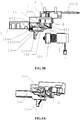
- Figs. 3A and 3B are cross-sectional views taken from Fig. 1 along A-A direction, which respectively show the residual-current protection device in the energy storage state and the energy release state according to an embodiment of the present application.
- the first portion of the energy storage mechanism mainly includes a locking wedge 13, a reset spring 14, a locking swing bar 15, and a stepped structure arranged on the driving rack 6 or integrated with the driving rack 6.
- the button 5 has a slot body fitting its sliding, and the locking wedge 13, the reset spring 14, the locking swing bar 15 and the stepped structure are substantially arranged within the slot body.
- the locking wedge 13 and the stepped structure are suitable to change the shape of the slot body so as to control the swing amplitude of the locking swing bar 15, and thus form a locking member. Further, the locking member and the locking swing bar 15 in turn form a locking unit in the first portion of the energy storage structure.
- the stepped structure has adjacent step faces 602 and 603 that are radially distal from inner walls of the slot body. The step face 603 is radially closer to inner walls of the slot body than the step face 602.
- the locking wedge 13 forms a linkage with the button 5 via the reset spring 14, and has a bevel 1301 facing the step faces 602 and 603 and a plane 1302 that is roughly parallel to the movement direction of the button 5.
- the step faces 602 and 603 are arranged opposite to the bevel 1301.
- the locking swing bar 15 is mounted on the enclosure and may be a U-shaped swing bar.
- the locking swing bar 15 is fastened in a U-shaped slot 101 of the upper casing 1, and the swingable end is clamped within the slot body of the button 5 with its swing amplitude controlled because the locking wedge 13 and the step faces 602 and 603 change the shape of the slot body.
- Fig. 5 shows an assembly schematic view of the locking wedge 13. As illustrated in Fig. 5 , the locking wedge 13 has a hollow portion for accommodating the reset spring 14 via which the locking wedge 13 forms a linkage with the button 15.
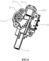
- Fig. 8 shows the second portion of the energy storage mechanism.
- an energy storage spring 10 is sleeved around an energy storage spring guide rod 11, and the energy storage spring 10 and the energy storage spring guide rod 11 are mounted within a spring slot 901 of the output rack 9.
- a cylindrical pin 12 is inserted in a cross hole 902 of the output rack 9 to push the ejection swing bar 16 to rotate.
- the ejection swing bar 16 has a bent portion 1601 and a contact claw 1602 arranged on top.
- the bent portion 1601 of the ejection swing bar 16 presses on the cylindrical pin 12 on the output rack 9.
- the cylindrical pin 12 pushes the bent portion 1601 of the ejection swing bar 16 to rotate, and the contact claw 1602 on top of the ejection swing bar goes up and triggers the trip lever of the circuit breaker to be tripped.
- the residual-current protection device may be further provided with a micro-switch mounted on the side of the driving rack 6 in an overlapping manner and fixed by pillars of the upper casing 1 and the lower casing 2.
- a boss 601 on the driving rack 6 presses the micro-switch 18, and NC and NO contacts of the micro-switch feed trip signals back to the control circuit.
- a tripper having the present protection device and a circuit breaker having a trip lever.
- the tripping output element strikes the trip lever to effect tripping when the energy storage mechanism is in energy release state.
- the present protection device may be mounted on a casing of a transformer 19 via a screw 17, and the energy storage spring guide rod 11 on the output rack 9 abuts against a boss 1901 of the casing of the transformer 19.
- the residual-current protection device has two states, i.e. the energy storage state and the energy release state.
- the energy storage state needs to be enabled by pressing the button 5.
- the button 5 is pressed and the button 5 pushes the driving rack 6 to drive, through the intermediate gear 7, the output rack 9 at a reduced speed to compress the energy storage spring 10 for energy storage, and the output rack 9 stores the energy and presses down the ejection swing bar 16 so that the ejection swing bar 16 goes down and is reset.
- the button 5 drives the driving rack 6 to go forwards to the locking wedge 13 so that locking swing bar 15 abuts against the bevel 1301 of the locking wedge 13. Since the upside of the locking swing bar 15 is restricted by the plane of the driving rack 6 and cannot swing, the locking wedge 13 is pressed by the locking swing bar 15 to move in a direction opposite to the moving direction of the button 5.
- the button 5 drives the driving rack 6 to move further, the stepped structure of the driving rack appears, and the locking swing bar 15 obtains a space for swing.
- the locking wedge 13 is pushed by the reset spring 14, and the bevel 1301 of the locking wedge 13 pushes the locking swing bar 15 to rotate.
- the locking wedge 13 is reset to the place 1302 of the locking wedge 13 and contacts with the locking swing bar 15, the place 1302 of the locking wedge 13 supports the locking swing bar 15.
- the output rack 9 drives the driving rack 6 through the intermediate gear 7 to slide for a small distance in a direction opposite to the direction for energy storage.
- the step face 603 of the driving rack 6 abuts against the locking swing bar 15 under the action of the energy storage spring 10.
- the locking swing bar 15 cannot swing as it is supported by the place 1302 of the locking wedge 13, the driving rack 6 springs back and is stopped by the locking swing bar 15, and thus the mechanism enters the energy storage state.
- the button 5 While the button 5 pushes the driving rack 6 for energy storage, the button 5 also pushes the flux transformer 3 to be reset.
- the boss 601 of the driving rack 6 at the energy storage position releases the micro-switch 18 button and feeds back a reset signal.
- the armature 301 pops out to push the button 5, and then the button 5 drives the locking wedge 13 to disengage from the locking swing bar 15.
- the output rack 9 drives the step face 602 of the driving rack 6 via the intermediate gear 7 to push the locking swing bar 15 to swing, the driving rack 6 pushes away the locking swing bar 15, and then the protection device releases energy.
- the cylindrical pin 12 on the output rack 9 pushes the bent portion 1601 of the ejection swing bar 16 so that the ejection swing bar 16 rotates.
- the contact claw 1602 on top of the ejection swing bar 16 goes up, thereby causing the trip lever of the circuit breaker to trip.
Landscapes
- Engineering & Computer Science (AREA)
- Power Engineering (AREA)
- Breakers (AREA)
Claims (10)
- Fehlerstrom-Schutzeinrichtung, die umfasst:einen Flusswandler (3), der ein Fehlerstromsignal aufnimmt;ein Auslöseausgabeelement (16), das EIN-/AUS-Signale ausgibt;einen Energiespeichermechanismus (10, 11), der geeignet ist, zwischen einem Energiespeicherzustand und einem Energiefreigabezustand umzuschalten, wobei der Energiespeichermechanismus eine Verriegelungseinheit (15) aufweist, die den Energiespeichermechanismus in dem Energiespeicherzustand verriegelt; undeinen durch den Flusswandler angetriebenen Übertragungsmechanismus, der das Auslöseausgabeelement (16) antreibt, sich zu bewegen, und den Energiespeichermechanismus antreibt, seinen Zustand umzuschalten, wobei der Übertragungsmechanismus gekennzeichnet ist durch:eine erste Zahnstange (6), die mit der Verriegelungseinheit zusammenwirkt;eine zweite Zahnstange (9), die das Auslöseausgabeelement antreibt; undein Untersetzungsgetriebe (7) mit einem großen Getriebeende, das mit der ersten Zahnstange in Eingriff ist, und einem kleinen Getriebeende, das mit der zweiten Zahnstange in Eingriff ist.
- Fehlerstrom-Schutzeinrichtung nach Anspruch 1, wobei der Übertragungsmechanismus eine Taste (5) und einen Nutkörper, in dem die Taste verschiebbar ist, umfasst.
- Fehlerstrom-Schutzeinrichtung nach Anspruch 2, wobei die Verriegelungseinheit eine in dem Nutkörper angeordnete U-förmige Pendelstange und ein Verriegelungselement umfasst, das geeignet ist, die Form des Nutkörpers zu ändern, um einen Pendelausschlag der Pendelstange zu steuern, wenn sich die Taste (5) verschiebt.
- Fehlerstrom-Schutzeinrichtung nach Anspruch 3, wobei das Verriegelungselement eine an der ersten Zahnstange angeordnete gestufte Struktur und einen über eine Rückstellfeder (14) mit der Taste (5) gekoppelten Keil umfasst, wobei Stufenflächen der gestuften Struktur gegenüber einer Keilfläche des Keils bereitgestellt sind.
- Fehlerstrom-Schutzeinrichtung nach Anspruch 2, wobei die Taste (5) und eine dazu gegenüberliegende Stirnfläche der ersten Zahnstange überlappende Abschnitte aufweisen.
- Fehlerstrom-Schutzeinrichtung nach Anspruch 2, wobei die Taste eine sich integral davon erstreckende Schubstange umfasst, die ein Rückstellen des Flusswandlers (3) auslöst.
- Fehlerstrom-Schutzeinrichtung nach Anspruch 1, wobei die zweite Zahnstange mit dem Auslöseausgabeelement (16) über eine Energiespeicherfeder gekoppelt ist.
- Fehlerstrom-Schutzeinrichtung nach Anspruch 1, wobei die Einrichtung einen an einer Seite der ersten Zahnstange montierten Mikroschalter (18) umfasst.
- Auslösevorrichtung, die umfasst:eine Fehlerstrom-Schutzeinrichtung nach einem der Ansprüche 1 bis 8; undeinen Schutzschalter mit einem Auslösehebel;wobei das Auslöseausgabeelement (16) den Auslösehebel anstößt, wenn der Energiespeichermechanismus in dem Energiefreigabezustand ist.
- Auslösevorrichtung nach Anspruch 9, wobei die Auslösevorrichtung einen Transformator (19) umfasst, wobei die Fehlerstrom-Schutzeinrichtung an einem Gehäuse des Transformators montiert ist.
Applications Claiming Priority (1)
| Application Number | Priority Date | Filing Date | Title |
|---|---|---|---|
| CN201820466598.7U CN208014635U (zh) | 2018-03-30 | 2018-03-30 | 剩余电流保护装置及脱扣器 |
Publications (2)
| Publication Number | Publication Date |
|---|---|
| EP3547345A1 EP3547345A1 (de) | 2019-10-02 |
| EP3547345B1 true EP3547345B1 (de) | 2020-12-23 |
Family
ID=63891843
Family Applications (1)
| Application Number | Title | Priority Date | Filing Date |
|---|---|---|---|
| EP19164907.8A Active EP3547345B1 (de) | 2018-03-30 | 2019-03-25 | Fehlerstromschutzvorrichtung und auslöser |
Country Status (3)
| Country | Link |
|---|---|
| US (1) | US10892128B2 (de) |
| EP (1) | EP3547345B1 (de) |
| CN (1) | CN208014635U (de) |
Families Citing this family (4)
| Publication number | Priority date | Publication date | Assignee | Title |
|---|---|---|---|---|
| CN112750642B (zh) * | 2019-10-31 | 2024-09-20 | 上海良信电器股份有限公司 | 一种旋转开关的远程控制切换装置 |
| CN113903606B (zh) * | 2020-07-07 | 2024-09-20 | 上海良信电器股份有限公司 | 一种储能脱扣模块及断路器 |
| CN112614764B (zh) * | 2021-02-07 | 2024-10-29 | 甄翠翠 | 一种可调式断路器 |
| CN113848473B (zh) * | 2021-10-22 | 2024-03-15 | 国网山东省电力公司商河县供电公司 | 一种剩余电流动作保护器检验装置 |
Family Cites Families (3)
| Publication number | Priority date | Publication date | Assignee | Title |
|---|---|---|---|---|
| DE102009020142B4 (de) * | 2009-05-04 | 2015-11-26 | Siemens Aktiengesellschaft | Vorrichtung zur gegenseitigen Verriegelung zweier Schalter, insbesondere Leistungsschalter |
| CN203071024U (zh) * | 2012-12-28 | 2013-07-17 | 常熟开关制造有限公司(原常熟开关厂) | 一种带剩余电流脱扣报警功能的漏电脱扣器 |
| FR3029009B1 (fr) * | 2014-11-21 | 2017-01-06 | Socomec Sa | Systeme de commande a declenchement pour pole de coupure et appareil de coupure |
-
2018
- 2018-03-30 CN CN201820466598.7U patent/CN208014635U/zh active Active
-
2019
- 2019-03-25 EP EP19164907.8A patent/EP3547345B1/de active Active
- 2019-03-27 US US16/366,181 patent/US10892128B2/en active Active
Non-Patent Citations (1)
| Title |
|---|
| None * |
Also Published As
| Publication number | Publication date |
|---|---|
| US20190304730A1 (en) | 2019-10-03 |
| US10892128B2 (en) | 2021-01-12 |
| CN208014635U (zh) | 2018-10-26 |
| EP3547345A1 (de) | 2019-10-02 |
Similar Documents
| Publication | Publication Date | Title |
|---|---|---|
| EP3547345B1 (de) | Fehlerstromschutzvorrichtung und auslöser | |
| KR100854387B1 (ko) | 트립기구모듈 및 이를 구비한 차단기 | |
| US11508540B2 (en) | Circuit breaker | |
| WO2017156978A1 (zh) | 断路器 | |
| EP3392898B1 (de) | Magnetische auslösevorrichtung für luftleistungsschalter | |
| EP3125266B1 (de) | Zweipoliger schalter mit tandemanordnung | |
| US10460898B2 (en) | Circuit breakers | |
| EP3343710B1 (de) | Positionsanzeiger für einen leistungsschalter | |
| CN210743865U (zh) | 一种低压真空断路器 | |
| EP4173019A1 (de) | Fehlerstrom-reststrom-anzeigemechanismus und schutzschalter mit fehlerstrom-anzeigemechanismus | |
| CN102064054A (zh) | 热电磁式脱扣器及其跳扣机构 | |
| CN215869171U (zh) | 一种插入式断路器 | |
| CN212010876U (zh) | 一种脱扣器力的放大及复位机构以及一种断路器 | |
| TW201227786A (en) | Tripping mechanism protecting from residual current and tripper | |
| CN109243929B (zh) | 一种带有可调型过载报警不脱扣功能的塑壳断路器 | |
| KR100905019B1 (ko) | 트립신호 출력장치를 구비한 차단기 | |
| US5519367A (en) | Circuit breaker logic switch system | |
| CN110676129B (zh) | 一种断路器合闸电阻脱扣机构及断路器 | |
| JP7293509B2 (ja) | クロスバー組立体及びそれを含むトリップ装置 | |
| US2944128A (en) | Counter-directionally releasable circuit breaker | |
| CN109686621B (zh) | 断路器的分励辅助组合附件 | |
| US20260081088A1 (en) | Remote control breakers | |
| CN224153283U (zh) | 一种漏电保护电磁脱扣机构 | |
| KR20200102272A (ko) | 배선용 차단기의 외부 조작 장치 | |
| CN217933675U (zh) | 一种控制与保护开关的脱扣装置 |
Legal Events
| Date | Code | Title | Description |
|---|---|---|---|
| PUAI | Public reference made under article 153(3) epc to a published international application that has entered the european phase |
Free format text: ORIGINAL CODE: 0009012 |
|
| STAA | Information on the status of an ep patent application or granted ep patent |
Free format text: STATUS: REQUEST FOR EXAMINATION WAS MADE |
|
| 17P | Request for examination filed |
Effective date: 20190325 |
|
| AK | Designated contracting states |
Kind code of ref document: A1 Designated state(s): AL AT BE BG CH CY CZ DE DK EE ES FI FR GB GR HR HU IE IS IT LI LT LU LV MC MK MT NL NO PL PT RO RS SE SI SK SM TR |
|
| AX | Request for extension of the european patent |
Extension state: BA ME |
|
| RBV | Designated contracting states (corrected) |
Designated state(s): AL AT BE BG CH CY CZ DE DK EE ES FI FR GB GR HR HU IE IS IT LI LT LU LV MC MK MT NL NO PL PT RO RS SE SI SK SM TR |
|
| RIC1 | Information provided on ipc code assigned before grant |
Ipc: H01H 83/14 20060101ALN20200603BHEP Ipc: H01H 71/12 20060101AFI20200603BHEP Ipc: H01H 71/10 20060101ALN20200603BHEP |
|
| GRAP | Despatch of communication of intention to grant a patent |
Free format text: ORIGINAL CODE: EPIDOSNIGR1 |
|
| STAA | Information on the status of an ep patent application or granted ep patent |
Free format text: STATUS: GRANT OF PATENT IS INTENDED |
|
| INTG | Intention to grant announced |
Effective date: 20200710 |
|
| GRAS | Grant fee paid |
Free format text: ORIGINAL CODE: EPIDOSNIGR3 |
|
| GRAA | (expected) grant |
Free format text: ORIGINAL CODE: 0009210 |
|
| STAA | Information on the status of an ep patent application or granted ep patent |
Free format text: STATUS: THE PATENT HAS BEEN GRANTED |
|
| AK | Designated contracting states |
Kind code of ref document: B1 Designated state(s): AL AT BE BG CH CY CZ DE DK EE ES FI FR GB GR HR HU IE IS IT LI LT LU LV MC MK MT NL NO PL PT RO RS SE SI SK SM TR |
|
| REG | Reference to a national code |
Ref country code: GB Ref legal event code: FG4D |
|
| REG | Reference to a national code |
Ref country code: DE Ref legal event code: R096 Ref document number: 602019001827 Country of ref document: DE |
|
| REG | Reference to a national code |
Ref country code: AT Ref legal event code: REF Ref document number: 1348536 Country of ref document: AT Kind code of ref document: T Effective date: 20210115 |
|
| REG | Reference to a national code |
Ref country code: IE Ref legal event code: FG4D |
|
| PG25 | Lapsed in a contracting state [announced via postgrant information from national office to epo] |
Ref country code: FI Free format text: LAPSE BECAUSE OF FAILURE TO SUBMIT A TRANSLATION OF THE DESCRIPTION OR TO PAY THE FEE WITHIN THE PRESCRIBED TIME-LIMIT Effective date: 20201223 Ref country code: RS Free format text: LAPSE BECAUSE OF FAILURE TO SUBMIT A TRANSLATION OF THE DESCRIPTION OR TO PAY THE FEE WITHIN THE PRESCRIBED TIME-LIMIT Effective date: 20201223 Ref country code: GR Free format text: LAPSE BECAUSE OF FAILURE TO SUBMIT A TRANSLATION OF THE DESCRIPTION OR TO PAY THE FEE WITHIN THE PRESCRIBED TIME-LIMIT Effective date: 20210324 Ref country code: NO Free format text: LAPSE BECAUSE OF FAILURE TO SUBMIT A TRANSLATION OF THE DESCRIPTION OR TO PAY THE FEE WITHIN THE PRESCRIBED TIME-LIMIT Effective date: 20210323 |
|
| REG | Reference to a national code |
Ref country code: AT Ref legal event code: MK05 Ref document number: 1348536 Country of ref document: AT Kind code of ref document: T Effective date: 20201223 |
|
| REG | Reference to a national code |
Ref country code: NL Ref legal event code: MP Effective date: 20201223 |
|
| PG25 | Lapsed in a contracting state [announced via postgrant information from national office to epo] |
Ref country code: BG Free format text: LAPSE BECAUSE OF FAILURE TO SUBMIT A TRANSLATION OF THE DESCRIPTION OR TO PAY THE FEE WITHIN THE PRESCRIBED TIME-LIMIT Effective date: 20210323 Ref country code: SE Free format text: LAPSE BECAUSE OF FAILURE TO SUBMIT A TRANSLATION OF THE DESCRIPTION OR TO PAY THE FEE WITHIN THE PRESCRIBED TIME-LIMIT Effective date: 20201223 Ref country code: LV Free format text: LAPSE BECAUSE OF FAILURE TO SUBMIT A TRANSLATION OF THE DESCRIPTION OR TO PAY THE FEE WITHIN THE PRESCRIBED TIME-LIMIT Effective date: 20201223 |
|
| PG25 | Lapsed in a contracting state [announced via postgrant information from national office to epo] |
Ref country code: HR Free format text: LAPSE BECAUSE OF FAILURE TO SUBMIT A TRANSLATION OF THE DESCRIPTION OR TO PAY THE FEE WITHIN THE PRESCRIBED TIME-LIMIT Effective date: 20201223 Ref country code: NL Free format text: LAPSE BECAUSE OF FAILURE TO SUBMIT A TRANSLATION OF THE DESCRIPTION OR TO PAY THE FEE WITHIN THE PRESCRIBED TIME-LIMIT Effective date: 20201223 |
|
| REG | Reference to a national code |
Ref country code: LT Ref legal event code: MG9D |
|
| PG25 | Lapsed in a contracting state [announced via postgrant information from national office to epo] |
Ref country code: PT Free format text: LAPSE BECAUSE OF FAILURE TO SUBMIT A TRANSLATION OF THE DESCRIPTION OR TO PAY THE FEE WITHIN THE PRESCRIBED TIME-LIMIT Effective date: 20210423 Ref country code: RO Free format text: LAPSE BECAUSE OF FAILURE TO SUBMIT A TRANSLATION OF THE DESCRIPTION OR TO PAY THE FEE WITHIN THE PRESCRIBED TIME-LIMIT Effective date: 20201223 Ref country code: LT Free format text: LAPSE BECAUSE OF FAILURE TO SUBMIT A TRANSLATION OF THE DESCRIPTION OR TO PAY THE FEE WITHIN THE PRESCRIBED TIME-LIMIT Effective date: 20201223 Ref country code: CZ Free format text: LAPSE BECAUSE OF FAILURE TO SUBMIT A TRANSLATION OF THE DESCRIPTION OR TO PAY THE FEE WITHIN THE PRESCRIBED TIME-LIMIT Effective date: 20201223 Ref country code: EE Free format text: LAPSE BECAUSE OF FAILURE TO SUBMIT A TRANSLATION OF THE DESCRIPTION OR TO PAY THE FEE WITHIN THE PRESCRIBED TIME-LIMIT Effective date: 20201223 Ref country code: SK Free format text: LAPSE BECAUSE OF FAILURE TO SUBMIT A TRANSLATION OF THE DESCRIPTION OR TO PAY THE FEE WITHIN THE PRESCRIBED TIME-LIMIT Effective date: 20201223 Ref country code: SM Free format text: LAPSE BECAUSE OF FAILURE TO SUBMIT A TRANSLATION OF THE DESCRIPTION OR TO PAY THE FEE WITHIN THE PRESCRIBED TIME-LIMIT Effective date: 20201223 |
|
| PG25 | Lapsed in a contracting state [announced via postgrant information from national office to epo] |
Ref country code: PL Free format text: LAPSE BECAUSE OF FAILURE TO SUBMIT A TRANSLATION OF THE DESCRIPTION OR TO PAY THE FEE WITHIN THE PRESCRIBED TIME-LIMIT Effective date: 20201223 Ref country code: AT Free format text: LAPSE BECAUSE OF FAILURE TO SUBMIT A TRANSLATION OF THE DESCRIPTION OR TO PAY THE FEE WITHIN THE PRESCRIBED TIME-LIMIT Effective date: 20201223 |
|
| REG | Reference to a national code |
Ref country code: DE Ref legal event code: R097 Ref document number: 602019001827 Country of ref document: DE |
|
| PG25 | Lapsed in a contracting state [announced via postgrant information from national office to epo] |
Ref country code: IS Free format text: LAPSE BECAUSE OF FAILURE TO SUBMIT A TRANSLATION OF THE DESCRIPTION OR TO PAY THE FEE WITHIN THE PRESCRIBED TIME-LIMIT Effective date: 20210423 |
|
| PG25 | Lapsed in a contracting state [announced via postgrant information from national office to epo] |
Ref country code: MC Free format text: LAPSE BECAUSE OF FAILURE TO SUBMIT A TRANSLATION OF THE DESCRIPTION OR TO PAY THE FEE WITHIN THE PRESCRIBED TIME-LIMIT Effective date: 20201223 Ref country code: AL Free format text: LAPSE BECAUSE OF FAILURE TO SUBMIT A TRANSLATION OF THE DESCRIPTION OR TO PAY THE FEE WITHIN THE PRESCRIBED TIME-LIMIT Effective date: 20201223 |
|
| PLBE | No opposition filed within time limit |
Free format text: ORIGINAL CODE: 0009261 |
|
| STAA | Information on the status of an ep patent application or granted ep patent |
Free format text: STATUS: NO OPPOSITION FILED WITHIN TIME LIMIT |
|
| PG25 | Lapsed in a contracting state [announced via postgrant information from national office to epo] |
Ref country code: DK Free format text: LAPSE BECAUSE OF FAILURE TO SUBMIT A TRANSLATION OF THE DESCRIPTION OR TO PAY THE FEE WITHIN THE PRESCRIBED TIME-LIMIT Effective date: 20201223 |
|
| 26N | No opposition filed |
Effective date: 20210924 |
|
| REG | Reference to a national code |
Ref country code: BE Ref legal event code: MM Effective date: 20210331 |
|
| PG25 | Lapsed in a contracting state [announced via postgrant information from national office to epo] |
Ref country code: ES Free format text: LAPSE BECAUSE OF FAILURE TO SUBMIT A TRANSLATION OF THE DESCRIPTION OR TO PAY THE FEE WITHIN THE PRESCRIBED TIME-LIMIT Effective date: 20201223 Ref country code: LU Free format text: LAPSE BECAUSE OF NON-PAYMENT OF DUE FEES Effective date: 20210325 Ref country code: IE Free format text: LAPSE BECAUSE OF NON-PAYMENT OF DUE FEES Effective date: 20210325 |
|
| PG25 | Lapsed in a contracting state [announced via postgrant information from national office to epo] |
Ref country code: SI Free format text: LAPSE BECAUSE OF FAILURE TO SUBMIT A TRANSLATION OF THE DESCRIPTION OR TO PAY THE FEE WITHIN THE PRESCRIBED TIME-LIMIT Effective date: 20201223 |
|
| PG25 | Lapsed in a contracting state [announced via postgrant information from national office to epo] |
Ref country code: IS Free format text: LAPSE BECAUSE OF FAILURE TO SUBMIT A TRANSLATION OF THE DESCRIPTION OR TO PAY THE FEE WITHIN THE PRESCRIBED TIME-LIMIT Effective date: 20210423 |
|
| PG25 | Lapsed in a contracting state [announced via postgrant information from national office to epo] |
Ref country code: BE Free format text: LAPSE BECAUSE OF NON-PAYMENT OF DUE FEES Effective date: 20210331 |
|
| REG | Reference to a national code |
Ref country code: CH Ref legal event code: PL |
|
| PG25 | Lapsed in a contracting state [announced via postgrant information from national office to epo] |
Ref country code: LI Free format text: LAPSE BECAUSE OF NON-PAYMENT OF DUE FEES Effective date: 20220331 Ref country code: CH Free format text: LAPSE BECAUSE OF NON-PAYMENT OF DUE FEES Effective date: 20220331 |
|
| PG25 | Lapsed in a contracting state [announced via postgrant information from national office to epo] |
Ref country code: CY Free format text: LAPSE BECAUSE OF FAILURE TO SUBMIT A TRANSLATION OF THE DESCRIPTION OR TO PAY THE FEE WITHIN THE PRESCRIBED TIME-LIMIT Effective date: 20201223 |
|
| PG25 | Lapsed in a contracting state [announced via postgrant information from national office to epo] |
Ref country code: HU Free format text: LAPSE BECAUSE OF FAILURE TO SUBMIT A TRANSLATION OF THE DESCRIPTION OR TO PAY THE FEE WITHIN THE PRESCRIBED TIME-LIMIT; INVALID AB INITIO Effective date: 20190325 |
|
| PG25 | Lapsed in a contracting state [announced via postgrant information from national office to epo] |
Ref country code: MK Free format text: LAPSE BECAUSE OF FAILURE TO SUBMIT A TRANSLATION OF THE DESCRIPTION OR TO PAY THE FEE WITHIN THE PRESCRIBED TIME-LIMIT Effective date: 20201223 |
|
| PG25 | Lapsed in a contracting state [announced via postgrant information from national office to epo] |
Ref country code: TR Free format text: LAPSE BECAUSE OF FAILURE TO SUBMIT A TRANSLATION OF THE DESCRIPTION OR TO PAY THE FEE WITHIN THE PRESCRIBED TIME-LIMIT Effective date: 20201223 |
|
| PG25 | Lapsed in a contracting state [announced via postgrant information from national office to epo] |
Ref country code: MT Free format text: LAPSE BECAUSE OF FAILURE TO SUBMIT A TRANSLATION OF THE DESCRIPTION OR TO PAY THE FEE WITHIN THE PRESCRIBED TIME-LIMIT Effective date: 20201223 |
|
| PGFP | Annual fee paid to national office [announced via postgrant information from national office to epo] |
Ref country code: GB Payment date: 20260324 Year of fee payment: 8 |
|
| PGFP | Annual fee paid to national office [announced via postgrant information from national office to epo] |
Ref country code: DE Payment date: 20260319 Year of fee payment: 8 |
|
| PGFP | Annual fee paid to national office [announced via postgrant information from national office to epo] |
Ref country code: IT Payment date: 20260324 Year of fee payment: 8 |
|
| PGFP | Annual fee paid to national office [announced via postgrant information from national office to epo] |
Ref country code: FR Payment date: 20260320 Year of fee payment: 8 |