EP3546999A1 - Optical cable and outer skin removal method - Google Patents
Optical cable and outer skin removal method Download PDFInfo
- Publication number
- EP3546999A1 EP3546999A1 EP17875672.2A EP17875672A EP3546999A1 EP 3546999 A1 EP3546999 A1 EP 3546999A1 EP 17875672 A EP17875672 A EP 17875672A EP 3546999 A1 EP3546999 A1 EP 3546999A1
- Authority
- EP
- European Patent Office
- Prior art keywords
- tensile strength
- strength members
- optical fiber
- sheath
- optical
- Prior art date
- Legal status (The legal status is an assumption and is not a legal conclusion. Google has not performed a legal analysis and makes no representation as to the accuracy of the status listed.)
- Granted
Links
Images



Classifications
-
- G—PHYSICS
- G02—OPTICS
- G02B—OPTICAL ELEMENTS, SYSTEMS OR APPARATUS
- G02B6/00—Light guides; Structural details of arrangements comprising light guides and other optical elements, e.g. couplings
- G02B6/46—Processes or apparatus adapted for installing or repairing optical fibres or optical cables
- G02B6/56—Processes for repairing optical cables
- G02B6/566—Devices for opening or removing the mantle
-
- G—PHYSICS
- G02—OPTICS
- G02B—OPTICAL ELEMENTS, SYSTEMS OR APPARATUS
- G02B6/00—Light guides; Structural details of arrangements comprising light guides and other optical elements, e.g. couplings
- G02B6/44—Mechanical structures for providing tensile strength and external protection for fibres, e.g. optical transmission cables
- G02B6/4401—Optical cables
- G02B6/4429—Means specially adapted for strengthening or protecting the cables
- G02B6/443—Protective covering
- G02B6/4432—Protective covering with fibre reinforcements
-
- G—PHYSICS
- G02—OPTICS
- G02B—OPTICAL ELEMENTS, SYSTEMS OR APPARATUS
- G02B6/00—Light guides; Structural details of arrangements comprising light guides and other optical elements, e.g. couplings
- G02B6/44—Mechanical structures for providing tensile strength and external protection for fibres, e.g. optical transmission cables
-
- G—PHYSICS
- G02—OPTICS
- G02B—OPTICAL ELEMENTS, SYSTEMS OR APPARATUS
- G02B6/00—Light guides; Structural details of arrangements comprising light guides and other optical elements, e.g. couplings
- G02B6/44—Mechanical structures for providing tensile strength and external protection for fibres, e.g. optical transmission cables
- G02B6/4479—Manufacturing methods of optical cables
- G02B6/4486—Protective covering
-
- G—PHYSICS
- G02—OPTICS
- G02B—OPTICAL ELEMENTS, SYSTEMS OR APPARATUS
- G02B6/00—Light guides; Structural details of arrangements comprising light guides and other optical elements, e.g. couplings
- G02B6/44—Mechanical structures for providing tensile strength and external protection for fibres, e.g. optical transmission cables
- G02B6/4479—Manufacturing methods of optical cables
- G02B6/449—Twisting
Definitions
- the present invention relates to an optical cable and a sheath removing method.
- Patent Literature 1 describes an optical fiber cable to be laid in a microduct (thin tubular duct) by air blown installation. Patent Literature 1 describes that three tensile strength members are buried in a sheath at 120-degree intervals around a loose tube (tube housing a plurality of optical fibers with filler capable of stopping water).
- Patent Literature 2 describes an optical cable housing, in a sheath, an optical fiber unit formed by wrapping a plurality of optical fibers with a wrapping tape. Patent Literature 2 describes that two tensile strength members are buried in the sheath in such a manner as to sandwich a housing part housing the optical fiber unit.
- the tensile strength members described in Patent Literature 1 are arranged in a twisted state so as to be in contact with the loose tube.
- the tensile strength members are longitudinally attached in a state of being in contact with a member such as the optical fiber unit described in Patent Literature 2 (aggregation formed by wrapping a plurality of optical fibers with a wrapping tape), instead of a loose tube, on an inner side of the tensile strength members.
- the optical fiber unit described in Patent Literature 2 (aggregation formed by wrapping a plurality of optical fibers with a wrapping tape)
- the tensile strength members come to dig into the inner part (optical fiber unit), and this may cause damage to the optical fibers and an increase in transmission loss.
- An objective of the invention is to provide a new optical cable from which optical fibers are easily taken out.
- a main aspect of the invention to achieve the above objective is an optical cable including: an optical fiber unit in which a plurality of optical fibers are wrapped with a wrapping tape; at least three tensile strength members that are arranged on an outer side of the optical fiber unit at intervals in a circumferential direction; and a sheath that coats the optical fiber unit and the tensile strength members, wherein the tensile strength members are arranged in parallel with the optical fiber unit, the sheath is formed between the optical fiber unit and the tensile strength members, an inner wall surface of the sheath formed between the optical fiber unit and the tensile strength members protrudes toward a cable center in comparison with an inner wall surface of the sheath arranged with none of the tensile strength members, and a portion of the wrapping tape arranged on the inner wall surface protruding toward the cable center are depressed toward the cable center.
- optical fibers can easily be taken out.
- an optical cable including: an optical fiber unit in which a plurality of optical fibers are wrapped with a wrapping tape; at least three tensile strength members that are arranged on an outer side of the optical fiber unit at intervals in a circumferential direction; and a sheath that coats the optical fiber unit and the tensile strength members, wherein the tensile strength members are arranged in parallel with the optical fiber unit, the sheath is formed between the optical fiber unit and the tensile strength members, an inner wall surface of the sheath formed between the optical fiber unit and the tensile strength members protrudes toward a cable center in comparison with an inner wall surface of the sheath arranged with none of the tensile strength members, and a portion of the wrapping tape arranged on the inner wall surface protruding toward the cable center are depressed toward the cable center.
- the number of the tensile strength members of the optical cable is three. In this way, it is possible to obtain an optical cable having an isotropic bending direction with the fewest possible tensile strength members.
- an inner radius of the depressed portion of the wrapping tape is r
- an inner radius of a non-depressed portion of the wrapping tape is R
- the degree of depression H (%) is 20% or lower. In this way, an increase in transmission loss of the optical fiber can be suppressed.
- a tangent line on an outer side of two adjacent ones of the tensile strength members is positioned on an outer side of the optical fiber unit. In this way, damage to the optical fiber unit can be prevented.
- part of the optical fiber unit is positioned on an outer side of a tangent line on an outer side of two adjacent ones of the tensile strength members. In this way, the optical fibers are easily taken out.
- a sheath removing method including: (1) preparing an optical cable including an optical fiber unit in which a plurality of optical fibers are wrapped with a wrapping tape, at least three tensile strength members that are arranged on an outer side of the optical fiber unit at intervals in a circumferential direction, and a sheath that coats the optical fiber unit and the tensile strength members, the tensile strength members being arranged in parallel with the optical fiber unit; and (2) removing the sheath by causing a blade of a tool to touch the sheath of the optical cable so that the blade of the tool crosses the length direction of the optical cable and moves the tool in the length direction.
- the tool is moved in the length direction while the blade of the tool is being guided by the tensile strength members. This makes it easier for an operator to remove the sheath.
- the blade of the tool is in contact with two adjacent ones of the tensile strength members. In this way, a blade of a tool can be prevented from digging further.
- the wrapping tape is deformed so as to be depressed toward an inner side with the blade moving in the length direction. In this way, the optical fibers are easily taken out.
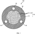
- Fig. 1 is a cross-sectional view of an optical cable 100 according to a present embodiment.
- the optical cable 100 according to the present embodiment includes an optical fiber unit 10, at least three tensile strength members 20, and a sheath 30.
- the optical fiber unit 10 is a unit (aggregation) formed by wrapping the plurality of optical fibers 3 with a wrapping tape 14.
- the optical fiber unit 10 is also referred to as an "optical cable core", an "optical fiber core”, a “core unit”, or simply a “unit”, or the like in some cases.
- the optical fiber unit 10 includes a plurality of bundle units 11 (refer to Fig. 2A ) each formed by bundling a plurality of optical fiber ribbons 1 with a bundling member 12 and is formed by wrapping the plurality of bundle units 11 with the wrapping tape 14.
- the bundle of the plurality of optical fibers 3 wrapped with the wrapping tape 14 is not limited to one constituted of the plurality of bundle units 11 and may be formed, for example, by bundling a number of single optical fibers 3.
- Fig. 2A is an explanatory diagram of the bundle unit 11.
- the bundle unit 11 has a structure in which bundles of the plurality of optical fibers 3 are bundled with the bundling member 12.
- the bundle unit 11 is sometimes referred to as a "subunit" or the like.
- the bundling member 12 is a thread-like, string-like, or tape-like member that can bundle the plurality of optical fibers 3.
- the bundle unit 11 can be distinguished from another bundle unit 11, based on an identification color of the bundling member 12. Note that an identification mark may be formed on the bundling member 12.
- the plurality of optical fibers 3 are bundled by winding two bundling members 12 in an S-Z configuration.
- the plurality of optical fibers 3 may be bundled by winding a single bundling member 12 around the optical fibers 3 in a spiral manner.
- the bundles of the optical fibers 3 are formed by bundling the plurality of intermittently connected optical fiber ribbons 1.
- Fig. 2B is an explanatory diagram of the intermittently connected optical fiber ribbon 1.
- the drawing on the right side of Fig. 2B is a cross-sectional view taken along A-A or B-B in a perspective view on the left side.
- a direction parallel with the optical fibers 3 constituting the optical fiber ribbon 1 is referred to as a "length direction”.
- a direction in which the plurality of optical fibers 3 constituting the optical fiber ribbon 1 are aligned is referred to as a "width direction".
- the intermittently connected optical fiber ribbon 1 is an optical fiber ribbon 1 including the plurality of optical fibers 3 arranged side by side and connected intermittently. Two adjacent ones of the optical fibers 3 are connected with a connection part 5.
- a plurality of connection parts 5 connecting two adjacent optical fibers 3 are arranged intermittently in the length direction.
- the plurality of connection parts 5 of the optical fiber ribbon 1 are arranged intermittently and two-dimensionally in the length direction and the width direction.
- the connection parts 5 are formed by, after application of ultraviolet curing resin to serve as connection agent, irradiating the ultraviolet curing resin with ultraviolet rays for solidification.
- the connection parts 5 may be formed of thermoplastic resin. Regions other than the connection parts 5 between the two adjacent optical fibers 2 constitute non-connected parts 7 (separation parts).
- the two adjacent optical fibers 3 are not restrained.
- the optical fiber ribbon 1 can be rolled up into a cylindrical form (a bundle), or folded up, and the multitude of optical fibers 3 can be bundled with high density.
- an operator breaks the connection parts 5 by, for example, tearing off the optical fibers 3.
- the intermittently connected optical fiber ribbon 1 is not limited to that illustrated in Fig. 2B .
- the number of optical fibers of the optical fiber ribbon 1 may be changed.
- the arrangement of the intermittently arranged connection parts 5 may be changed.
- the wrapping tape 14 is a member that wraps the plurality of optical fibers 3. Wrapping the optical fibers 3 with the wrapping tape 14 can prevent, when coating is applied with molten resin to form the sheath 30, the optical fibers 3 from being buried in (digging into) the sheath 30.
- a polyimide tape, a polyester tape, a polypropylene tape, a polyethylene tape, or the like is used for the wrapping tape 14.
- nonwoven fabric may be used as the wrapping tape 14. In this case, tape-like nonwoven fabric made of polyimide, polyester, polypropylene, polyethylene, or the like is used.
- the wrapping tape 14 may be nonwoven fabric with a film, such as a polyester film, being stuck thereto.
- the wrapping tape 14 is formed by attaching (or applying) water-absorbing powder to a tape-like base. Hence, the wrapping tape 14 functions as a water-absorbing tape.
- the water-absorbing powder is granular or powdery material having water absorbing properties (water-absorbing material) .
- the water-absorbing powder may be attached (applied) to a surface of the tape-like base or may be provided in a sandwiched manner between tape-like bases made of two pieces of nonwoven fabric. At the time when water is absorbed (the water-absorbing powder absorbs water), granular or powdery water-absorbing powder expands to be jellied (swelling) .
- a superabsorbent starchy, cellulosic, polyacrylic acid, polyvinyl alcohol, or polyoxyethylene material having a grain size of 5 to 30 ⁇ m, a mixture of these, or the like may be used, for example.
- the jellied water-absorbing powder fills the gap in the optical cable 100 to stop water in the optical cable 100.
- the base itself may have water absorbing property.
- the wrapping tape 14 may not necessarily have water absorbing properties.
- the tensile strength members 20 are members that hold against contraction of the sheath 30 and suppress distortion and bending applied to the optical fiber unit 10 (especially, the optical fibers 3) due to the contraction of the sheath 30.
- the tensile strength members 20 are linear members and are buried in the sheath 30.
- a material of the tensile strength members 20 a nonmetallic material or a metallic material may be used.
- GFRP glass FRP
- KFRP Kevler
- FRP fiber reinforced plastics
- FRP fiber reinforced plastics
- polyethylene fiber reinforced plastics reinforced by polyethylene fiber may be used, for example.
- a metallic wire such as a steel wire, may be used.
- the optical cable 100 includes at least three tensile strength members 20.
- the three tensile strength members 20 are buried in the sheath 30.
- the three tensile strength members 20 are arranged at equal intervals (here, intervals of 120 degrees) in a circumferential direction. With at least three tensile strength members 20 being thus arranged at intervals in the circumferential direction, the optical cable 100 can have isotropic bending directional properties.
- the optical cable 100 having isotropic bending directional properties can be obtained with the fewest possible tensile strength members 20. Note that, however, the number of tensile strength members 20 is not limited to three and may be four or more.
- the N tensile strength members 20 are arranged at intervals of 360 degrees/N in the circumferential direction.
- the optical cable 100 includes four tensile strength members 20, the four tensile strength members 20 are arranged at 90-degree intervals in the circumferential direction.
- a housing part of the optical fiber unit 10 is formed in the region surrounded by at least three tensile strength members 20, a housing part of the optical fiber unit 10 is formed.
- the optical cable 100 is easily bent in particular directions (bending directions having the line linking the two tensile strength members 20 as a neutral axis) and is difficult to be bent in other directions. If the bending directions of the cable are thus limited, characteristics of air blowing to a microduct deteriorate. In contrast to this, in the case of the optical cable 100 according to the present embodiment, isotropic bending directional properties can be obtained, and hence excellent characteristics of air blowing to a microduct can be obtained.
- the sheath 30 is a member for coating the optical fiber unit 10 and the tensile strength members 20.
- the outside shape (cross section) of the sheath 30 is circular.
- resin such as polyvinyl chloride (PVC), polyethylene (PE), nylon (trademark), fluorinated ethylene, or polypropylene (PP), may be used, for example.
- PVC polyvinyl chloride
- PE polyethylene
- nylon trademark
- PP polypropylene
- high-density polyethylene, medium-density polyethylene, low-density polyethylene, straight-chain low-density polyethylene, or the like may be used.
- a polyolefin compound containing, as fire retardant, a hydrated metal compound, such as magnesium hydroxide or aluminum hydroxide, may be used, for example.
- a member different from the optical fiber unit 10 and the tensile strength members 20 may be buried in the sheath 30.
- the optical fiber unit 10 (especially, the optical fibers 3) may be distorted by contraction of the sheath 30 at the time of cooling, and a signal loss of the optical fibers 3 may consequently increase.
- load at the time of contraction of the sheath 30 is less likely to be applied to the tensile strength members 20, and this makes the load less likely to be applied to the optical fiber unit 10.
- the tensile strength members 20 are arranged in parallel with the optical fiber unit 10. Assume a case where the tensile strength members 20 are twisted on an outer side of the optical fiber unit 10. In this case, the tensile strength members 20 on the outer side of the optical fiber unit 10 stand in the way at the time of taking the optical fibers 3 out from the optical fiber unit 10. Consequently, the tensile strength members 20 need to be cut off, and this reduces workability. In contrast to this, because the tensile strength members 20 are merely arranged in parallel with the optical fiber unit 10 in the present embodiment, the optical fibers 3 can easily be taken out only by removing the sheath 30. Note that a method of taking out the optical fibers 3 (a sheath removing method of the optical cable 100) according to the present embodiment will be described later.
- the tensile strength members 20 are twisted, the tensile strength members 20 are prevented from digging into the optical fiber unit 10 when the optical cable 100 is bent, even if the sheath 30 is not formed between the optical fiber unit 10 and the tensile strength members 20. In this case, however, as already described above, because the tensile strength members 20 need to be cut off to take out the optical fibers 3, workability is reduced.
- the structure of the tensile strength members 20 being arranged in parallel with the optical fiber unit 10 is adopted while the structure of the sheath 30 being formed between the optical fiber unit 10 (more specifically, the wrapping tape 14) and the tensile strength members 20 is adopted.
- the tensile strength members 20 are arranged in parallel with the optical fiber unit 10 without being in contact with the optical fiber unit 10.
- the sheath 30 serves as a partition separating the optical fiber unit 10 and the tensile strength members 20. This can prevent the tensile strength members 20 from digging into the optical fiber unit 10 even when the optical cable 100 is bent.
- the sheath 30 is formed on an inner side of the tensile strength members 20, and hence the housing space for the optical fiber unit 10 is narrowed.
- the sheath 30 formed between the optical fiber unit 10 and the tensile strength members 20 is reduced in thickness to enlarge the housing space for the optical fiber unit 10, the function of the sheath 30 as a partition for separating the optical fiber unit 10 and the tensile strength members 20 may be reduced.
- the tensile strength members 20 may not fulfill an original function of resisting contraction of the sheath 30.
- an inner wall surface of the sheath 30 formed between the optical fiber unit 10 and the tensile strength members 20 is formed to protrude toward a cable center in comparison with an inner wall surface of the sheath 30 on which no tensile strength members 20 are arranged.
- the thickness of the sheath 30 around the tensile strength members 20 can be secured.
- the function of the sheath 30 as the partition for separating the optical fiber unit 10 and the tensile strength members 20 and the original function of the tensile strength members 20 to resist contraction of the sheath 30 can be fulfilled.
- each portion of the wrapping tape 14, the portion being arranged on the inner wall surface of the sheath 30 protruding toward the cable center is formed to depress toward the cable center.
- each portion, of the wrapping tape 14, in which the sheath 30 does not protrude is not depressed, and hence a certain housing space for the optical fiber unit 10 can be secured.
- the conflicting problems of securing the thickness of the sheath 30 around the tensile strength members 20 (including the inner side of the tensile strength members 20) and securing a certain housing space for the optical fiber unit 10 can both be solved.
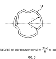
- Fig. 3 is an explanatory diagram of a degree of depression of the wrapping tape 14.
- the drawing illustrates a shape of the wrapping tape 14 at a cross section of the optical cable 100.
- r denotes the inner radius of the wrapping tape 14 on the inner side of the tensile strength members 20.
- r in the drawing denotes the inner radius at a depressed portion of the wrapping tape 14.
- R denotes the inner radius of a portion of the wrapping tape 14, the portion not corresponding to the inner side of the tensile strength members 20.
- R in the drawing denotes the inner radius at a non-depressed portion of the wrapping tape 14.
- H R ⁇ r / R * 100
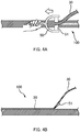
- Fig. 4A and Fig. 4B are explanatory diagrams of a sheath removing method of the optical cable 100 according to the present embodiment.
- Fig. 4B explanatory diagram of an operation of removing the sheath 30 being seen from a side
- a tool 50 shaving tool, sheath removing tool
- only a blade 51 is illustrated for the convenience of explanation.
- the operator in sheath removing of the optical cable 100, the operator causes the blade 51 (flat blade) of the tool 50 to touch the sheath 30 of the optical cable 100 so that the blade edge of the blade 51 of the tool 50 crosses the length direction and moves the blade 51 of the tool 50 in the length direction, to thereby remove the sheath 30.
- the operator removes the sheath 30 with the blade 51 (flat blade) of the tool 50 as planing with a plane or peeling with a peeler.
- the direction of moving the tool 50 is a direction orthogonal to the blade edge of the blade 51 (flat blade).
- the tensile strength members 20 arranged at intervals in the circumferential direction on the outer side of the optical fiber unit 10 are arranged in parallel with the optical fiber unit 10. Hence, the operator can access, by removing the sheath 30 in the length direction, the optical fiber unit 10 through any of gaps between the tensile strength members 20. If the tensile strength members 20 are twisted on the outer side of the optical fiber unit 10, the tensile strength members 20 on the outer side of the optical fiber unit 10 lie in the way in a state where the sheath 30 is only removed in the length direction. In this case, it is difficult to access the optical fiber unit 10 through the gaps between the tensile strength members 20 (this consequently requires cutting of the tensile strength members 20 or the like).
- the operator can guide the blade 51 with the tensile strength members 20, at the time of moving the blade 51 of the tool 50 in the length direction.
- the tensile strength members 20 have a function as a guide for the tool 50.
- the blade 51 of the tool 50 coming into contact with the tensile strength members 20 can prevent further digging into the optical cable 100.
- the tensile strength members 20 also have a function of preventing damage to the optical fiber unit 10.
- Fig. 5A is a partially enlarged view of a cross section of the optical cable 100.
- a tangent line on the outer side of two adjacent tensile strength members 20 is illustrated by a dotted line.
- the blade 51 of the tool 50 coming into contact with the two tensile strength members 20 can prevent further digging into the optical cable 100.
- the tangent line on the outer side of the two tensile strength members 20 indicates the limit depth for the blade edge of the tool 50.
- the tangent line on the outer side of the two tensile strength members 20 (dotted line in the drawing) is positioned on the outer side of the optical fiber unit 10 (specifically, the wrapping tape 14).
- This can prevent the blade 51 of the tool 50 from coming into contact with the optical fiber unit 10 (especially, the optical fibers 3) and can hence prevent damage to the optical fiber unit 10.
- the operator needs to access the optical fiber unit 10 by removing the sheath 30 with the blade 51 of the tool 50 and thereafter tearing the thin-walled sheath 30 remaining on the outer side of the optical fiber unit 10.
- the tangent line on the outer side of the two tensile strength members 20 may be positioned on an inner side of the sheath 30.
- part of the optical fiber unit 10 may be positioned on the outer side of the tangent line on the outer side of the two tensile strength members 20.
- each portion of the wrapping tape 14, the portion being arranged on the inner wall surface of the sheath 30 protruding toward the cable center is formed to depress toward the cable center. For this reason, when the blade 51 of the tool 50 comes into contact with the wrapping tape 14, a contacting portion is easily depressed to the inside, which makes the wrapping tape 14 less likely to be damaged.
- the tangent line on the outer side of the two tensile strength members 20 is also allowed to be positioned on the inner side of the sheath 30.
- the optical cable 100 illustrated in Fig. 1 was manufactured.
- the three tensile strength members 20 arranged at 120-degree intervals are arranged in parallel with the optical fiber unit 10 without being in contact with the optical fiber unit 10.
- the optical cable 100 of the first example includes 72 optical fibers (72 optical fibers 3 are housed in the optical fiber unit 10 of the optical cable 100 of the first example).
- optical cables described in Patent Literature 1 JP 2010-204368A ) were manufactured.
- three tensile strength members 20 arranged at 120-degree intervals are arranged on an outer side of a loose tube in a twisted state.
- the optical cable of the first comparative example includes 12 optical fibers
- the optical cable of the second comparative example includes 72 optical fibers (the number of optical fibers housed in the loose tube is 12 in the first comparative example and 72 in the second comparative example).
- Fig. 6 is a graph of measurement results of flexural rigidities of the optical cables.
- the flexural rigidity (unit: N/m2) of each optical cable was measured, by changing the flexural direction in steps of 30 degrees, in each of the flexural directions.
- the optical cable of the first example has almost isotropic flexural rigidity.
- the flexural rigidity of the optical cable 100 of the first example is four to five times greater than that of the first comparative example and is one-and-a-half to two times greater than that of the second comparative example.
- Fig. 7 is a graph of measurement results of air-blowing performance.
- a microduct having an inner diameter of 8 mm was prepared and was laid in an 8 shape having a circumference of approximately 125 m.
- Each optical cable was then air-blown installed in the microduct to measure a distance by the air-blowing.
- the transfer distance of the optical cable of the first example was 3000 m, and excellent air-blowing characteristics are confirmed (the transmission distance of each of the optical cables of the comparative examples was 2500 m).
- the optical cables 100 (refer to Fig. 1 ) having a plurality of different rates of depression H (%) were manufactured.
- Each of the optical cables 100 includes 72 optical fibers (72 optical fibers 3 are housed in the optical fiber unit 10 of each of the optical cables 100).
- the outer diameter of each of the optical cables 100 was measured.
- the outer diameter of an optical cable having the degree of depression H (%) of 0% (optical cable with no depression) evaluations about the effects of reduction in diameter were made on the outer diameter of each of the optical cables 100 with respect to the outer diameter of the reference optical cable.
- air-blowing performance of each of the optical cables 100 was measured.
- the method of measuring air-blowing performance is as already described.
- a case of having air-blowing characteristics equal to or higher than those of the above-described comparative examples was evaluated as good.
- each of the optical cables 100 were measured.
- a transmission loss (dB/km) of each of the optical fibers 3 was measured.
- evaluations were made on stripping characteristics of the optical cables 100. As illustrated in Fig. 4A and Fig. 4B , evaluations on stripping characteristics were made based on whether the optical fibers 3 were damaged through removing (stripping) of the sheath of each of the optical cables 100 using a tool.
- each of the optical cables 100 according to the example has air-blowing characteristics equal to or higher than those of the above-described comparative examples.
- the degree of depression H is 7.5% or higher
- air-blowing characteristics equal to or higher than those of the comparative examples can be obtained. This is considered to be because the higher the degree of depression H (%) is, the smaller the outer diameter of the optical cable 100 can be made, and this makes it easier for the optical cable 100 to be air-blown installed in a small microduct.
- the degree of depression H (%) is 25% or higher, the transmission characteristics are evaluated as poor.
- the reason of deterioration of the transmission characteristics is considered to be because of lateral pressure being applied to the optical fibers 3 at the time when the optical cables 100 were bent. In view of this, it is confirmed that the degree of depression H (%) is preferably 20% or lower.
- optical cables with four to six tensile strength members arranged at equal intervals in a circumferential direction were manufactured. Note that the structure of each of the optical cables of the third example is approximately the same as that of the optical cable of the first example, except for the number of the tensile strength members N.
- the tensile strength members are arranged in parallel with the optical fiber unit, the sheath is formed between the optical fiber unit and the tensile strength members, portions of the inner wall surface of the sheath formed between the optical fiber unit and the tensile strength members protrude toward the cable center in comparison with portions of the inner wall surface of the sheath arranged with no tensile strength members, and portions of a wrapping tape arranged on the portions of the inner wall surface of the sheath protruding toward the cable center are configured to be depressed toward the cable center.
- the number of tensile strength members is N.
- Fig. 8 is a graph of measurement results of flexural rigidities of the optical cables according to the third example (and the first example) .
- the flexural rigidity (unit: N/m2) of each optical cable was measured, by changing the flexural direction in steps of 30 degrees, in each of the flexural directions.
Landscapes
- Physics & Mathematics (AREA)
- General Physics & Mathematics (AREA)
- Optics & Photonics (AREA)
- Engineering & Computer Science (AREA)
- Manufacturing & Machinery (AREA)
- Light Guides In General And Applications Therefor (AREA)
- Insulated Conductors (AREA)
Abstract
Description
- The present invention relates to an optical cable and a sheath removing method.
-
Patent Literature 1 describes an optical fiber cable to be laid in a microduct (thin tubular duct) by air blown installation.Patent Literature 1 describes that three tensile strength members are buried in a sheath at 120-degree intervals around a loose tube (tube housing a plurality of optical fibers with filler capable of stopping water). - Patent Literature 2 describes an optical cable housing, in a sheath, an optical fiber unit formed by wrapping a plurality of optical fibers with a wrapping tape. Patent Literature 2 describes that two tensile strength members are buried in the sheath in such a manner as to sandwich a housing part housing the optical fiber unit.
-
- Patent Literature 1:
JP 2010-204368A - Patent Literature 2:
JP 2015-169756A - In the optical fiber cable described in
Patent Literature 1, three tensile strength members are arranged in a twisted state around the loose tube. With this structure, simply removing the sheath to take out the optical fibers from the optical fiber cable leaves the tensile strength members in the way, and this makes it difficult to take out the optical fibers. For this reason, to take the optical fibers out from the optical fiber cable described inPatent Literature 1, it is necessary, for example, to cut off the tensile strength members. - The tensile strength members described in
Patent Literature 1 are arranged in a twisted state so as to be in contact with the loose tube. However, assume that the tensile strength members are longitudinally attached in a state of being in contact with a member such as the optical fiber unit described in Patent Literature 2 (aggregation formed by wrapping a plurality of optical fibers with a wrapping tape), instead of a loose tube, on an inner side of the tensile strength members. In such a case, when the optical cable is bent, the tensile strength members come to dig into the inner part (optical fiber unit), and this may cause damage to the optical fibers and an increase in transmission loss. - An objective of the invention is to provide a new optical cable from which optical fibers are easily taken out.
- A main aspect of the invention to achieve the above objective is an optical cable including: an optical fiber unit in which a plurality of optical fibers are wrapped with a wrapping tape; at least three tensile strength members that are arranged on an outer side of the optical fiber unit at intervals in a circumferential direction; and a sheath that coats the optical fiber unit and the tensile strength members, wherein the tensile strength members are arranged in parallel with the optical fiber unit, the sheath is formed between the optical fiber unit and the tensile strength members, an inner wall surface of the sheath formed between the optical fiber unit and the tensile strength members protrudes toward a cable center in comparison with an inner wall surface of the sheath arranged with none of the tensile strength members, and a portion of the wrapping tape arranged on the inner wall surface protruding toward the cable center are depressed toward the cable center.
- Other features of the invention are made clear by the following description and the drawings.
- With the present invention, optical fibers can easily be taken out.
-
-
Fig. 1 is a cross-sectional view of anoptical cable 100 according to a present embodiment. -
Fig. 2A is an explanatory diagram of abundle unit 11.Fig. 2B is an explanatory diagram of an intermittently connectedoptical fiber ribbon 1. -
Fig. 3 is an explanatory diagram of a degree of depression of awrapping tape 14. -
Fig. 4A and Fig. 4B are explanatory diagrams of a sheath removing method of theoptical cable 100 according to the present embodiment. -
Fig. 5A and Fig. 5B are partially enlarged views of a cross section of theoptical cable 100. -
Fig. 6 is a graph of measurement results of flexural rigidities of optical cables. -
Fig. 7 is a graph of measurement results of air-blowing performance. -
Fig. 8 is a graph of measurement results of flexural rigidities of optical cables according to a third example. -
Fig. 9 is a graph of measurement results of air-blowing performance in the third example. - At least the following matters are made clear from the following description and the drawings.
- Disclosed is an optical cable including: an optical fiber unit in which a plurality of optical fibers are wrapped with a wrapping tape; at least three tensile strength members that are arranged on an outer side of the optical fiber unit at intervals in a circumferential direction; and a sheath that coats the optical fiber unit and the tensile strength members, wherein the tensile strength members are arranged in parallel with the optical fiber unit, the sheath is formed between the optical fiber unit and the tensile strength members, an inner wall surface of the sheath formed between the optical fiber unit and the tensile strength members protrudes toward a cable center in comparison with an inner wall surface of the sheath arranged with none of the tensile strength members, and a portion of the wrapping tape arranged on the inner wall surface protruding toward the cable center are depressed toward the cable center. With this optical cable, the optical fibers are easily taken out.
- It is preferable that the number of the tensile strength members of the optical cable is three. In this way, it is possible to obtain an optical cable having an isotropic bending direction with the fewest possible tensile strength members.
- It is preferable that assuming that an inner radius of the depressed portion of the wrapping tape is r, an inner radius of a non-depressed portion of the wrapping tape is R, and a degree of depression H (%) is H = (R - r)/R * 100, the degree of depression H (%) is 20% or lower. In this way, an increase in transmission loss of the optical fiber can be suppressed.
- It is preferable that a tangent line on an outer side of two adjacent ones of the tensile strength members is positioned on an outer side of the optical fiber unit. In this way, damage to the optical fiber unit can be prevented.
- It is preferable that part of the optical fiber unit is positioned on an outer side of a tangent line on an outer side of two adjacent ones of the tensile strength members. In this way, the optical fibers are easily taken out.
- Disclosed is a sheath removing method including: (1) preparing an optical cable including an optical fiber unit in which a plurality of optical fibers are wrapped with a wrapping tape, at least three tensile strength members that are arranged on an outer side of the optical fiber unit at intervals in a circumferential direction, and a sheath that coats the optical fiber unit and the tensile strength members, the tensile strength members being arranged in parallel with the optical fiber unit; and (2) removing the sheath by causing a blade of a tool to touch the sheath of the optical cable so that the blade of the tool crosses the length direction of the optical cable and moves the tool in the length direction. With this sheath removing method, optical fibers are easily taken out.
- It is preferable that the tool is moved in the length direction while the blade of the tool is being guided by the tensile strength members. This makes it easier for an operator to remove the sheath.
- It is preferable that in removing the sheath, the blade of the tool is in contact with two adjacent ones of the tensile strength members. In this way, a blade of a tool can be prevented from digging further.
- It is preferable that in removing the sheath with the tool, the wrapping tape is deformed so as to be depressed toward an inner side with the blade moving in the length direction. In this way, the optical fibers are easily taken out.
-
Fig. 1 is a cross-sectional view of anoptical cable 100 according to a present embodiment. Theoptical cable 100 according to the present embodiment includes anoptical fiber unit 10, at least threetensile strength members 20, and asheath 30. - The
optical fiber unit 10 is a unit (aggregation) formed by wrapping the plurality ofoptical fibers 3 with awrapping tape 14. Theoptical fiber unit 10 is also referred to as an "optical cable core", an "optical fiber core", a "core unit", or simply a "unit", or the like in some cases. In the present embodiment, theoptical fiber unit 10 includes a plurality of bundle units 11 (refer toFig. 2A ) each formed by bundling a plurality ofoptical fiber ribbons 1 with a bundlingmember 12 and is formed by wrapping the plurality ofbundle units 11 with the wrappingtape 14. Note that the bundle of the plurality ofoptical fibers 3 wrapped with the wrappingtape 14 is not limited to one constituted of the plurality ofbundle units 11 and may be formed, for example, by bundling a number of singleoptical fibers 3. -
Fig. 2A is an explanatory diagram of thebundle unit 11. Thebundle unit 11 has a structure in which bundles of the plurality ofoptical fibers 3 are bundled with the bundlingmember 12. Thebundle unit 11 is sometimes referred to as a "subunit" or the like. The bundlingmember 12 is a thread-like, string-like, or tape-like member that can bundle the plurality ofoptical fibers 3. Thebundle unit 11 can be distinguished from anotherbundle unit 11, based on an identification color of the bundlingmember 12. Note that an identification mark may be formed on the bundlingmember 12. In thebundle unit 11 in the drawing, the plurality ofoptical fibers 3 are bundled by winding two bundlingmembers 12 in an S-Z configuration. However, the plurality ofoptical fibers 3 may be bundled by winding asingle bundling member 12 around theoptical fibers 3 in a spiral manner. The bundles of theoptical fibers 3 are formed by bundling the plurality of intermittently connectedoptical fiber ribbons 1. -
Fig. 2B is an explanatory diagram of the intermittently connectedoptical fiber ribbon 1. The drawing on the right side ofFig. 2B is a cross-sectional view taken along A-A or B-B in a perspective view on the left side. In the following description, as illustrated inFig. 2B , a direction parallel with theoptical fibers 3 constituting theoptical fiber ribbon 1 is referred to as a "length direction". A direction in which the plurality ofoptical fibers 3 constituting theoptical fiber ribbon 1 are aligned is referred to as a "width direction". - The intermittently connected
optical fiber ribbon 1 is anoptical fiber ribbon 1 including the plurality ofoptical fibers 3 arranged side by side and connected intermittently. Two adjacent ones of theoptical fibers 3 are connected with aconnection part 5. A plurality ofconnection parts 5 connecting two adjacentoptical fibers 3 are arranged intermittently in the length direction. The plurality ofconnection parts 5 of theoptical fiber ribbon 1 are arranged intermittently and two-dimensionally in the length direction and the width direction. Theconnection parts 5 are formed by, after application of ultraviolet curing resin to serve as connection agent, irradiating the ultraviolet curing resin with ultraviolet rays for solidification. Note that theconnection parts 5 may be formed of thermoplastic resin. Regions other than theconnection parts 5 between the two adjacent optical fibers 2 constitute non-connected parts 7 (separation parts). In thenon-connected parts 7, the two adjacentoptical fibers 3 are not restrained. Thus, theoptical fiber ribbon 1 can be rolled up into a cylindrical form (a bundle), or folded up, and the multitude ofoptical fibers 3 can be bundled with high density. To separate any of theoptical fibers 3 from theoptical fiber ribbon 1, an operator breaks theconnection parts 5 by, for example, tearing off theoptical fibers 3. - Note that the intermittently connected
optical fiber ribbon 1 is not limited to that illustrated inFig. 2B . For example, the number of optical fibers of theoptical fiber ribbon 1 may be changed. Moreover, the arrangement of the intermittently arrangedconnection parts 5 may be changed. - The wrapping
tape 14 is a member that wraps the plurality ofoptical fibers 3. Wrapping theoptical fibers 3 with the wrappingtape 14 can prevent, when coating is applied with molten resin to form thesheath 30, theoptical fibers 3 from being buried in (digging into) thesheath 30. A polyimide tape, a polyester tape, a polypropylene tape, a polyethylene tape, or the like is used for the wrappingtape 14. Alternatively, nonwoven fabric may be used as the wrappingtape 14. In this case, tape-like nonwoven fabric made of polyimide, polyester, polypropylene, polyethylene, or the like is used. The wrappingtape 14 may be nonwoven fabric with a film, such as a polyester film, being stuck thereto. - The wrapping
tape 14 is formed by attaching (or applying) water-absorbing powder to a tape-like base. Hence, the wrappingtape 14 functions as a water-absorbing tape. The water-absorbing powder is granular or powdery material having water absorbing properties (water-absorbing material) . The water-absorbing powder may be attached (applied) to a surface of the tape-like base or may be provided in a sandwiched manner between tape-like bases made of two pieces of nonwoven fabric. At the time when water is absorbed (the water-absorbing powder absorbs water), granular or powdery water-absorbing powder expands to be jellied (swelling) . As such water-absorbing powder, a superabsorbent starchy, cellulosic, polyacrylic acid, polyvinyl alcohol, or polyoxyethylene material having a grain size of 5 to 30 µm, a mixture of these, or the like may be used, for example. The jellied water-absorbing powder fills the gap in theoptical cable 100 to stop water in theoptical cable 100. Note that the base itself may have water absorbing property. The wrappingtape 14 may not necessarily have water absorbing properties. - The
tensile strength members 20 are members that hold against contraction of thesheath 30 and suppress distortion and bending applied to the optical fiber unit 10 (especially, the optical fibers 3) due to the contraction of thesheath 30. Thetensile strength members 20 are linear members and are buried in thesheath 30. As a material of thetensile strength members 20, a nonmetallic material or a metallic material may be used. As the nonmetallic material, glass FRP (GFRP), aramid fiber reinforced plastics reinforced by Kevler (trademark) (KFRP), or fiber reinforced plastics (FRP), such as polyethylene fiber reinforced plastics reinforced by polyethylene fiber, may be used, for example. As the metallic material, a metallic wire, such as a steel wire, may be used. - The
optical cable 100 according to the present embodiment includes at least threetensile strength members 20. Here, the threetensile strength members 20 are buried in thesheath 30. The threetensile strength members 20 are arranged at equal intervals (here, intervals of 120 degrees) in a circumferential direction. With at least threetensile strength members 20 being thus arranged at intervals in the circumferential direction, theoptical cable 100 can have isotropic bending directional properties. In a case that the number oftensile strength members 20 is three, theoptical cable 100 having isotropic bending directional properties can be obtained with the fewest possibletensile strength members 20. Note that, however, the number oftensile strength members 20 is not limited to three and may be four or more. In a case that theoptical cable 100 includes Ntensile strength members 20, the Ntensile strength members 20 are arranged at intervals of 360 degrees/N in the circumferential direction. For example, in a case that theoptical cable 100 includes fourtensile strength members 20, the fourtensile strength members 20 are arranged at 90-degree intervals in the circumferential direction. In the region surrounded by at least threetensile strength members 20, a housing part of theoptical fiber unit 10 is formed. - Assume a case where two
tensile strength members 20 are arranged to sandwich theoptical fiber unit 10. In this case, theoptical cable 100 is easily bent in particular directions (bending directions having the line linking the twotensile strength members 20 as a neutral axis) and is difficult to be bent in other directions. If the bending directions of the cable are thus limited, characteristics of air blowing to a microduct deteriorate. In contrast to this, in the case of theoptical cable 100 according to the present embodiment, isotropic bending directional properties can be obtained, and hence excellent characteristics of air blowing to a microduct can be obtained. - The
sheath 30 is a member for coating theoptical fiber unit 10 and thetensile strength members 20. The outside shape (cross section) of thesheath 30 is circular. As a material of thesheath 30, resin, such as polyvinyl chloride (PVC), polyethylene (PE), nylon (trademark), fluorinated ethylene, or polypropylene (PP), may be used, for example. In the case of using polyethylene (PE), high-density polyethylene, medium-density polyethylene, low-density polyethylene, straight-chain low-density polyethylene, or the like may be used. As a material of thesheath 30, a polyolefin compound containing, as fire retardant, a hydrated metal compound, such as magnesium hydroxide or aluminum hydroxide, may be used, for example. Note that a member different from theoptical fiber unit 10 and thetensile strength members 20 may be buried in thesheath 30. - In the formation of the
sheath 30 by extrusion molding of molten resin, the optical fiber unit 10 (especially, the optical fibers 3) may be distorted by contraction of thesheath 30 at the time of cooling, and a signal loss of theoptical fibers 3 may consequently increase. By burying thetensile strength members 20 in thesheath 30, load at the time of contraction of thesheath 30 is less likely to be applied to thetensile strength members 20, and this makes the load less likely to be applied to theoptical fiber unit 10. - In the present embodiment, the
tensile strength members 20 are arranged in parallel with theoptical fiber unit 10. Assume a case where thetensile strength members 20 are twisted on an outer side of theoptical fiber unit 10. In this case, thetensile strength members 20 on the outer side of theoptical fiber unit 10 stand in the way at the time of taking theoptical fibers 3 out from theoptical fiber unit 10. Consequently, thetensile strength members 20 need to be cut off, and this reduces workability. In contrast to this, because thetensile strength members 20 are merely arranged in parallel with theoptical fiber unit 10 in the present embodiment, theoptical fibers 3 can easily be taken out only by removing thesheath 30. Note that a method of taking out the optical fibers 3 (a sheath removing method of the optical cable 100) according to the present embodiment will be described later. - In the case of arranging the
tensile strength members 20 and theoptical fiber unit 10 in parallel as in the present embodiment, assume that theoptical fiber unit 10 and thetensile strength members 20 are in contact with each other without forming thesheath 30 between theoptical fiber unit 10 and thetensile strength members 20. With this structure, no partition is formed between theoptical fiber unit 10 and thetensile strength members 20, and this causes thetensile strength members 20 to dig into theoptical fiber unit 10 when theoptical cable 100 is bent. This may consequently damage theoptical fibers 3 or increase a signal loss of theoptical fibers 3. If thetensile strength members 20 are twisted, thetensile strength members 20 are prevented from digging into theoptical fiber unit 10 when theoptical cable 100 is bent, even if thesheath 30 is not formed between theoptical fiber unit 10 and thetensile strength members 20. In this case, however, as already described above, because thetensile strength members 20 need to be cut off to take out theoptical fibers 3, workability is reduced. - To address this issue, in the present embodiment, the structure of the
tensile strength members 20 being arranged in parallel with theoptical fiber unit 10 is adopted while the structure of thesheath 30 being formed between the optical fiber unit 10 (more specifically, the wrapping tape 14) and thetensile strength members 20 is adopted. In other words, in the present embodiment, thetensile strength members 20 are arranged in parallel with theoptical fiber unit 10 without being in contact with theoptical fiber unit 10. By forming thesheath 30 between the wrappingtape 14 of theoptical fiber unit 10 and thetensile strength members 20, thesheath 30 serves as a partition separating theoptical fiber unit 10 and thetensile strength members 20. This can prevent thetensile strength members 20 from digging into theoptical fiber unit 10 even when theoptical cable 100 is bent. - In a case of the structure of the
sheath 30 being formed between theoptical fiber unit 10 and thetensile strength members 20, thesheath 30 is formed on an inner side of thetensile strength members 20, and hence the housing space for theoptical fiber unit 10 is narrowed. However, if thesheath 30 formed between theoptical fiber unit 10 and thetensile strength members 20 is reduced in thickness to enlarge the housing space for theoptical fiber unit 10, the function of thesheath 30 as a partition for separating theoptical fiber unit 10 and thetensile strength members 20 may be reduced. In addition, if thesheath 30 formed between theoptical fiber unit 10 and thetensile strength members 20 is reduced in thickness to increase the housing space for theoptical fiber unit 10, thetensile strength members 20 may not fulfill an original function of resisting contraction of thesheath 30. - In contrast to this, in the present embodiment, an inner wall surface of the
sheath 30 formed between theoptical fiber unit 10 and thetensile strength members 20 is formed to protrude toward a cable center in comparison with an inner wall surface of thesheath 30 on which notensile strength members 20 are arranged. With this structure, the thickness of thesheath 30 around the tensile strength members 20 (including the inner side of the tensile strength members 20) can be secured. Hence, the function of thesheath 30 as the partition for separating theoptical fiber unit 10 and thetensile strength members 20 and the original function of thetensile strength members 20 to resist contraction of thesheath 30 can be fulfilled. In the present embodiment, each portion of the wrappingtape 14, the portion being arranged on the inner wall surface of thesheath 30 protruding toward the cable center is formed to depress toward the cable center. With this structure, each portion, of the wrappingtape 14, in which thesheath 30 does not protrude is not depressed, and hence a certain housing space for theoptical fiber unit 10 can be secured. In other words, according to theoptical cable 100 of the present embodiment, the conflicting problems of securing the thickness of thesheath 30 around the tensile strength members 20 (including the inner side of the tensile strength members 20) and securing a certain housing space for theoptical fiber unit 10 can both be solved. -
Fig. 3 is an explanatory diagram of a degree of depression of the wrappingtape 14. The drawing illustrates a shape of the wrappingtape 14 at a cross section of theoptical cable 100. In the drawing, r denotes the inner radius of the wrappingtape 14 on the inner side of thetensile strength members 20. In other words, r in the drawing denotes the inner radius at a depressed portion of the wrappingtape 14. In the drawing, R denotes the inner radius of a portion of the wrappingtape 14, the portion not corresponding to the inner side of thetensile strength members 20. In other words, R in the drawing denotes the inner radius at a non-depressed portion of the wrappingtape 14. - Here, the degree of depression H (%) is defined by the following equation.

- In the
optical cable 100 of the present embodiment, the higher the degree of depression H is, the greater the area of the housing space (space on the inner side of thesheath 30, space of the optical fiber unit 10) with respect to the cross-sectional area of theoptical cable 100 becomes, which allows theoptical cable 100 to have a small outer diameter. If the degree of depression H is too high, however, theoptical fibers 3 are likely to receive lateral pressure when theoptical cable 100 is bent, and a transmission loss is likely to increase. In view of these, the degree of depression H (%) is preferably 20% or lower (to be described later). -
Fig. 4A and Fig. 4B are explanatory diagrams of a sheath removing method of theoptical cable 100 according to the present embodiment. InFig. 4B (explanatory diagram of an operation of removing thesheath 30 being seen from a side), with respect to a tool 50 (stripping tool, sheath removing tool), only ablade 51 is illustrated for the convenience of explanation. - In the present embodiment, in sheath removing of the
optical cable 100, the operator causes the blade 51 (flat blade) of thetool 50 to touch thesheath 30 of theoptical cable 100 so that the blade edge of theblade 51 of thetool 50 crosses the length direction and moves theblade 51 of thetool 50 in the length direction, to thereby remove thesheath 30. In other words, the operator removes thesheath 30 with the blade 51 (flat blade) of thetool 50 as planing with a plane or peeling with a peeler. Here, the direction of moving the tool 50 (length direction) is a direction orthogonal to the blade edge of the blade 51 (flat blade). - In the present embodiment, the
tensile strength members 20 arranged at intervals in the circumferential direction on the outer side of theoptical fiber unit 10 are arranged in parallel with theoptical fiber unit 10. Hence, the operator can access, by removing thesheath 30 in the length direction, theoptical fiber unit 10 through any of gaps between thetensile strength members 20. If thetensile strength members 20 are twisted on the outer side of theoptical fiber unit 10, thetensile strength members 20 on the outer side of theoptical fiber unit 10 lie in the way in a state where thesheath 30 is only removed in the length direction. In this case, it is difficult to access theoptical fiber unit 10 through the gaps between the tensile strength members 20 (this consequently requires cutting of thetensile strength members 20 or the like). - In addition, in the present embodiment, because the
tensile strength members 20 are arranged in parallel with theoptical fiber unit 10, the operator can guide theblade 51 with thetensile strength members 20, at the time of moving theblade 51 of thetool 50 in the length direction. In other words, thetensile strength members 20 have a function as a guide for thetool 50. Theblade 51 of thetool 50 coming into contact with thetensile strength members 20 can prevent further digging into theoptical cable 100. Hence, thetensile strength members 20 also have a function of preventing damage to theoptical fiber unit 10. -
Fig. 5A is a partially enlarged view of a cross section of theoptical cable 100. In the drawing, a tangent line on the outer side of two adjacenttensile strength members 20 is illustrated by a dotted line. - The
blade 51 of thetool 50 coming into contact with the twotensile strength members 20 can prevent further digging into theoptical cable 100. Thus, the tangent line on the outer side of the two tensile strength members 20 (dotted line in the drawing) indicates the limit depth for the blade edge of thetool 50. - In the present embodiment, as illustrated in
Fig. 5A , the tangent line on the outer side of the two tensile strength members 20 (dotted line in the drawing) is positioned on the outer side of the optical fiber unit 10 (specifically, the wrapping tape 14). This can prevent theblade 51 of thetool 50 from coming into contact with the optical fiber unit 10 (especially, the optical fibers 3) and can hence prevent damage to theoptical fiber unit 10. Note that, however, to take theoptical fibers 3 out from theoptical cable 100, the operator needs to access theoptical fiber unit 10 by removing thesheath 30 with theblade 51 of thetool 50 and thereafter tearing the thin-walled sheath 30 remaining on the outer side of theoptical fiber unit 10. - In contrast, as illustrated in
Fig. 5B , the tangent line on the outer side of the twotensile strength members 20 may be positioned on an inner side of thesheath 30. In other words, part of theoptical fiber unit 10 may be positioned on the outer side of the tangent line on the outer side of the twotensile strength members 20. The structure illustrated inFig. 5B has an advantage that, because theoptical fiber unit 10 is exposed when the operator removes thesheath 30 with theblade 51 of thetool 50, this makes access to theoptical fiber unit 10 easier. With the structure illustrated inFig. 5B , although theblade 51 of thetool 50 may come into contact with theoptical fiber unit 10, the wrappingtape 14 of theoptical fiber unit 10 is deformed with theblade 51 moving in the length direction so as to be depressed to the inside, and this can prevent damage to the optical fiber unit 10 (especially, the optical fibers 3). In particular, in the present embodiment, each portion of the wrappingtape 14, the portion being arranged on the inner wall surface of thesheath 30 protruding toward the cable center is formed to depress toward the cable center. For this reason, when theblade 51 of thetool 50 comes into contact with the wrappingtape 14, a contacting portion is easily depressed to the inside, which makes the wrappingtape 14 less likely to be damaged. Hence, as illustrated inFig. 5B , the tangent line on the outer side of the twotensile strength members 20 is also allowed to be positioned on the inner side of thesheath 30. - As a first example, the
optical cable 100 illustrated inFig. 1 was manufactured. In theoptical cable 100 of the first example, the threetensile strength members 20 arranged at 120-degree intervals are arranged in parallel with theoptical fiber unit 10 without being in contact with theoptical fiber unit 10. Theoptical cable 100 of the first example includes 72 optical fibers (72optical fibers 3 are housed in theoptical fiber unit 10 of theoptical cable 100 of the first example). - As a first comparative example and a second comparative example, optical cables described in Patent Literature 1 (
JP 2010-204368A tensile strength members 20 arranged at 120-degree intervals are arranged on an outer side of a loose tube in a twisted state. The optical cable of the first comparative example includes 12 optical fibers, while the optical cable of the second comparative example includes 72 optical fibers (the number of optical fibers housed in the loose tube is 12 in the first comparative example and 72 in the second comparative example). -
Fig. 6 is a graph of measurement results of flexural rigidities of the optical cables. To investigate the isotropic properties of the flexural rigidity of each cable, the flexural rigidity (unit: N/m2) of each optical cable was measured, by changing the flexural direction in steps of 30 degrees, in each of the flexural directions. As illustrated in the graph, it is confirmed that the optical cable of the first example has almost isotropic flexural rigidity. (Note that the flexural rigidity of theoptical cable 100 of the first example is four to five times greater than that of the first comparative example and is one-and-a-half to two times greater than that of the second comparative example.) -
Fig. 7 is a graph of measurement results of air-blowing performance. For the measurement of air-blowing performance, a microduct having an inner diameter of 8 mm was prepared and was laid in an 8 shape having a circumference of approximately 125 m. Each optical cable was then air-blown installed in the microduct to measure a distance by the air-blowing. The transfer distance of the optical cable of the first example was 3000 m, and excellent air-blowing characteristics are confirmed (the transmission distance of each of the optical cables of the comparative examples was 2500 m). - As a second example, the optical cables 100 (refer to
Fig. 1 ) having a plurality of different rates of depression H (%) were manufactured. Each of theoptical cables 100 includes 72 optical fibers (72optical fibers 3 are housed in theoptical fiber unit 10 of each of the optical cables 100). - To determine effects of the degree of depression H (%) on reduction in diameter, the outer diameter of each of the
optical cables 100 was measured. By using, as a reference, the outer diameter of an optical cable having the degree of depression H (%) of 0% (optical cable with no depression), evaluations about the effects of reduction in diameter were made on the outer diameter of each of theoptical cables 100 with respect to the outer diameter of the reference optical cable. - In addition, air-blowing performance of each of the
optical cables 100 was measured. The method of measuring air-blowing performance is as already described. A case of having air-blowing characteristics equal to or higher than those of the above-described comparative examples was evaluated as good. - In addition, transmission characteristics of each of the
optical cables 100 were measured. By using theoptical cable 100 having a length of 600 m and wound around a drum with a measurement wavelength of 1.55 µm under the environment with a temperature of 20 degrees, a transmission loss (dB/km) of each of theoptical fibers 3 was measured. A case where the transmission loss of theoptical fiber 3 having the greatest transmission loss was smaller than 0.2 dB/km was evaluated as good, while a case where the transmission loss was 0.3 dB/km or greater was evaluated as poor. - In addition, evaluations were made on stripping characteristics of the
optical cables 100. As illustrated inFig. 4A and Fig. 4B , evaluations on stripping characteristics were made based on whether theoptical fibers 3 were damaged through removing (stripping) of the sheath of each of theoptical cables 100 using a tool. - Evaluation results of the effects of reduction in diameter, air-blowing characteristics, transmission characteristics, and stripping characteristics of the
optical cables 100 having different rates of depression are as presented in the following table.[Table 1] DEGREE OF DEPRESSION H(%) OUTER DIAMETER (mm) EFFECTS ON REDUCTION IN DIAMETER (%) AIR-BLOWING CHARACTERISTICS TRANSMISSION CHARACTERISTICS STRIPPING CHARACTERISTICS AIR-BLOWING DISTANCE (m) EVALUATION TRANSMISSION LOSS (dB/km) EVALUATION 0 6.6 100.0 - - - - - 1.5 6.5 98.2 ∼2500 GOOD Max.<0.2 GOOD GOOD 2.5 6.4 97.0 ∼2500 GOOD Max.<0.2 GOOD GOOD 5 6.2 93.9 ∼2500 GOOD Max.<0.2 GOOD GOOD 7.5 6.0 90.9 >3000 GOOD Max.<0.2 GOOD GOOD 10 5.8 87.9 >3000 GOOD Max.<0.2 GOOD GOOD 15 5.4 81.8 >3000 GOOD Max.<0.2 GOOD GOOD 20 5.0 75.8 >3000 GOOD Max.<0.2 GOOD GOOD 25 4.6 69.7 >3000 GOOD Max.>0.3 POOR GOOD 30 4.2 63.6 >3000 GOOD Max.>0.3 POOR GOOD - It is confirmed, as presented in outer diameter (mm) and effects (%) of reduction in diameter in Table 1, that the higher the degree of depression H (%) is, the smaller the outer diameter of the
optical cable 100 can be made. - It is confirmed, as illustrated in air-blowing characteristics in Table 1, that each of the
optical cables 100 according to the example has air-blowing characteristics equal to or higher than those of the above-described comparative examples. In particular, it is confirmed that, when the degree of depression H is 7.5% or higher, air-blowing characteristics equal to or higher than those of the comparative examples can be obtained. This is considered to be because the higher the degree of depression H (%) is, the smaller the outer diameter of theoptical cable 100 can be made, and this makes it easier for theoptical cable 100 to be air-blown installed in a small microduct. - In contrast, as presented in the transmission characteristics in Table 1, when the degree of depression H (%) is 25% or higher, the transmission characteristics are evaluated as poor. The reason of deterioration of the transmission characteristics is considered to be because of lateral pressure being applied to the
optical fibers 3 at the time when theoptical cables 100 were bent. In view of this, it is confirmed that the degree of depression H (%) is preferably 20% or lower. - As presented in the evaluation results of stripping characteristics in Table 1, no damage to the
optical fibers 3 was found in any of theoptical cables 100. Hence, the sheath removing method illustrated inFig. 4A is confirmed to be effective to theoptical cable 100 having the structure illustrated inFig. 1 . - As a third example, optical cables with four to six tensile strength members arranged at equal intervals in a circumferential direction (intervals of 360 degrees/N in the circumferential direction, where N is the number of tensile strength members) were manufactured. Note that the structure of each of the optical cables of the third example is approximately the same as that of the optical cable of the first example, except for the number of the tensile strength members N. Hence, also in the third example, the tensile strength members are arranged in parallel with the optical fiber unit, the sheath is formed between the optical fiber unit and the tensile strength members, portions of the inner wall surface of the sheath formed between the optical fiber unit and the tensile strength members protrude toward the cable center in comparison with portions of the inner wall surface of the sheath arranged with no tensile strength members, and portions of a wrapping tape arranged on the portions of the inner wall surface of the sheath protruding toward the cable center are configured to be depressed toward the cable center. Assume that the number of tensile strength members is N. Each of the optical cables of N = 3, 4 includes 72 optical fibers, while each of the optical cables of N = 5, 6 includes 288 optical fibers.
-
Fig. 8 is a graph of measurement results of flexural rigidities of the optical cables according to the third example (and the first example) . To investigate the isotropic properties of the flexural rigidity of each cable, the flexural rigidity (unit: N/m2) of each optical cable was measured, by changing the flexural direction in steps of 30 degrees, in each of the flexural directions. As illustrated in the graph, it is also confirmed that the optical cables of the third example (N = 4 to 6), similar to the optical cable of the first example (N = 3), have almost isotropic flexural rigidities. -
Fig. 9 is a graph of measurement results of air-blowing performance according to the third example (and the first example). As presented in the measurement results, it is also confirmed for the optical cables of the third example (N = 4 and 6), similar to the optical cable of the first example (N = 3), to have excellent air-blowing characteristics. - The foregoing embodiments are for facilitating the understanding of the present invention, and are not to be construed as limiting the present invention. The present invention may be modified and/or improved without departing from the gist thereof, and it goes without saying that the present invention encompasses any equivalents thereof.
-
- 1:
- Optical fiber ribbon;
- 3:
- Optical fiber;
- 5:
- Connection part;
- 7:
- Non-connected part;
- 10:
- Optical fiber unit;
- 11:
- Bundle unit;
- 12:
- Bundling member;
- 14:
- Wrapping tape;
- 20:
- Tensile strength member;
- 30:
- Sheath;
- 50:
- Tool;
- 51:
- Blade;
- 100:
- Optical Cable.
Claims (9)
- An optical cable comprising:an optical fiber unit in which a plurality of optical fibers are wrapped with a wrapping tape;at least three tensile strength members that are arranged on an outer side of the optical fiber unit at intervals in a circumferential direction; anda sheath that coats the optical fiber unit and the tensile strength members, whereinthe tensile strength members are arranged in parallel with the optical fiber unit,the sheath is formed between the optical fiber unit and the tensile strength members,an inner wall surface of the sheath formed between the optical fiber unit and the tensile strength members protrudes toward a cable center in comparison with an inner wall surface of the sheath arranged with none of the tensile strength members, anda portion of the wrapping tape arranged on the inner wall surface protruding toward the cable center are depressed toward the cable center.
- The optical cable according to claim 1, wherein the number of the tensile strength members of the optical cable is three.
- The optical cable according to claim 1 or 2, wherein, assuming that
an inner radius of the depressed portion of the wrapping tape is r,
an inner radius of a non-depressed portion of the wrapping tape is R, and
a degree of depression H (%) is H = (R - r)/R * 100,
the degree of depression H (%) is 20% or lower. - The optical cable according to any one of claims 1 to 3, wherein a tangent line on an outer side of two adjacent ones of the tensile strength members is positioned on an outer side of the optical fiber unit.
- The optical cable according to any one of claims 1 to 3, wherein part of the optical fiber unit is positioned on an outer side of a tangent line on an outer side of two adjacent ones of the tensile strength members.
- A sheath removing method comprising:(1) preparing an optical cable including an optical fiber unit in which a plurality of optical fibers are wrapped with a wrapping tape, at least three tensile strength members that are arranged on an outer side of the optical fiber unit at intervals in a circumferential direction, and a sheath that coats the optical fiber unit and the tensile strength members, the tensile strength members being arranged in parallel with the optical fiber unit; and(2) removing the sheath by causing a blade of a tool to touch the sheath of the optical cable so that the blade of the tool crosses the length direction of the optical cable and moves the tool in the length direction.
- The sheath removing method according to claim 6, wherein the tool is moved in the length direction while the blade of the tool is being guided by the tensile strength members.
- The sheath removing method according to claim 7, wherein, in removing the sheath, the blade of the tool is in contact with two adjacent ones of the tensile strength members.
- The sheath removing method according to any one of claims 6 to 8, wherein, in removing the sheath with the tool, the wrapping tape is deformed so as to be depressed toward an inner side with the blade moving in the length direction.
Applications Claiming Priority (2)
| Application Number | Priority Date | Filing Date | Title |
|---|---|---|---|
| JP2016233839 | 2016-12-01 | ||
| PCT/JP2017/041103 WO2018101041A1 (en) | 2016-12-01 | 2017-11-15 | Optical cable and outer skin removal method |
Publications (3)
| Publication Number | Publication Date |
|---|---|
| EP3546999A1 true EP3546999A1 (en) | 2019-10-02 |
| EP3546999A4 EP3546999A4 (en) | 2020-06-24 |
| EP3546999B1 EP3546999B1 (en) | 2024-03-20 |
Family
ID=62242144
Family Applications (1)
| Application Number | Title | Priority Date | Filing Date |
|---|---|---|---|
| EP17875672.2A Active EP3546999B1 (en) | 2016-12-01 | 2017-11-15 | Optical cable and outer skin removal method |
Country Status (9)
| Country | Link |
|---|---|
| US (1) | US10775581B2 (en) |
| EP (1) | EP3546999B1 (en) |
| JP (1) | JP6527645B2 (en) |
| KR (1) | KR102167263B1 (en) |
| CN (1) | CN109844596B (en) |
| AU (1) | AU2017369091B2 (en) |
| CA (1) | CA3045786C (en) |
| ES (1) | ES2981083T3 (en) |
| WO (1) | WO2018101041A1 (en) |
Families Citing this family (7)
| Publication number | Priority date | Publication date | Assignee | Title |
|---|---|---|---|---|
| JP7156178B2 (en) * | 2019-06-04 | 2022-10-19 | 住友電気工業株式会社 | fiber optic cable |
| JP7310517B2 (en) * | 2019-10-03 | 2023-07-19 | 住友電気工業株式会社 | fiber optic cable |
| JP7156181B2 (en) * | 2019-06-19 | 2022-10-19 | 住友電気工業株式会社 | fiber optic cable |
| EP3988977B1 (en) * | 2019-06-19 | 2024-07-24 | Sumitomo Electric Industries, Ltd. | Optical fiber cable |
| JP7445787B2 (en) * | 2020-12-24 | 2024-03-07 | 株式会社フジクラ | Accommodation unit and roll |
| EP4343399A4 (en) * | 2021-05-18 | 2025-04-30 | Fujikura Ltd. | FIBER OPTIC CABLE |
| JP7856928B2 (en) * | 2022-12-19 | 2026-05-12 | Ntt株式会社 | Fiber optic cable |
Family Cites Families (23)
| Publication number | Priority date | Publication date | Assignee | Title |
|---|---|---|---|---|
| GB2170614A (en) * | 1985-01-24 | 1986-08-06 | Pirelli General Plc | Optical fibre cables |
| JP2507328B2 (en) * | 1986-06-25 | 1996-06-12 | 住友電気工業株式会社 | Optical cable |
| IT1202606B (en) * | 1987-03-02 | 1989-02-09 | Pirelli Cavi Spa | APPARATUS FOR THE MANUFACTURE OF FIBER OPTIC CABLES |
| DE4236251A1 (en) | 1992-10-20 | 1994-04-21 | Hoechst Ag | Stripper with tangential blade for protective sleeve of optical fibre - peels segment of sleeve from edge of fibre laid in groove having pref. up to 20 per cent greater dimension |
| FR2756935B1 (en) * | 1996-12-09 | 1999-01-08 | Alsthom Cge Alcatel | REINFORCED FIBER CABLE, WITH UNITUBE STRUCTURE |
| GB9826263D0 (en) * | 1998-11-30 | 1999-01-20 | Pirelli General Plc | Optical fibre cable manufacture |
| US6377738B1 (en) | 1998-12-04 | 2002-04-23 | Pirelli Cable Corporation | Optical fiber cable and core with a reinforced buffer tube having visible strength members and methods of manufacture thereof |
| US6771863B2 (en) * | 2001-12-14 | 2004-08-03 | Sci Systems, Inc. | Fiber optic cable |
| CN2746406Y (en) * | 2004-11-16 | 2005-12-14 | 光元先进科技股份有限公司 | Optical cable structure |
| GB0600445D0 (en) * | 2006-01-11 | 2006-02-15 | Ocean Cable Technologies Ltd | Cable Gripper |
| KR20080098225A (en) * | 2007-05-04 | 2008-11-07 | 엘에스전선 주식회사 | Loose tube type optical cable with improved tension member structure |
| JP2010204368A (en) | 2009-03-03 | 2010-09-16 | Fujikura Ltd | Single tube type optical fiber cable |
| CN102565972A (en) * | 2010-12-29 | 2012-07-11 | 山东太平洋光缆有限公司 | Armored tactical optical cable |
| KR101581413B1 (en) * | 2011-03-30 | 2015-12-30 | 가부시키가이샤후지쿠라 | Optical fiber coating removing device and method of removing coating |
| JP2013195746A (en) | 2012-03-21 | 2013-09-30 | Fujikura Ltd | Optical fiber cable and manufacturing method thereof |
| US8620124B1 (en) * | 2012-09-26 | 2013-12-31 | Corning Cable Systems Llc | Binder film for a fiber optic cable |
| JP6196838B2 (en) * | 2013-08-23 | 2017-09-13 | 株式会社フジクラ | Optical fiber cable and intermediate post-branching method of optical fiber cable |
| JP6086324B2 (en) * | 2013-11-21 | 2017-03-01 | 株式会社フジクラ | Fiber optic cable |
| CN104977678B (en) * | 2014-01-02 | 2017-11-28 | 陈春华 | Light unit and the optical cable using the light unit |
| JP5719052B1 (en) * | 2014-03-06 | 2015-05-13 | 株式会社フジクラ | Optical cable |
| JP2016080747A (en) | 2014-10-10 | 2016-05-16 | 住友電気工業株式会社 | Optical fiber cable |
| JP3198825U (en) * | 2015-05-13 | 2015-07-23 | 株式会社曙産業 | Peeler |
| CN105301718A (en) * | 2015-10-30 | 2016-02-03 | 成都格瑞思文化传播有限公司 | Compressive optical cable structure |
-
2017
- 2017-11-15 ES ES17875672T patent/ES2981083T3/en active Active
- 2017-11-15 AU AU2017369091A patent/AU2017369091B2/en active Active
- 2017-11-15 WO PCT/JP2017/041103 patent/WO2018101041A1/en not_active Ceased
- 2017-11-15 EP EP17875672.2A patent/EP3546999B1/en active Active
- 2017-11-15 JP JP2018553758A patent/JP6527645B2/en active Active
- 2017-11-15 KR KR1020197005378A patent/KR102167263B1/en active Active
- 2017-11-15 US US16/465,628 patent/US10775581B2/en active Active
- 2017-11-15 CN CN201780062398.3A patent/CN109844596B/en active Active
- 2017-11-15 CA CA3045786A patent/CA3045786C/en active Active
Also Published As
| Publication number | Publication date |
|---|---|
| CA3045786C (en) | 2022-07-26 |
| AU2017369091B2 (en) | 2020-04-16 |
| JPWO2018101041A1 (en) | 2019-06-24 |
| US20190310437A1 (en) | 2019-10-10 |
| KR20190030751A (en) | 2019-03-22 |
| CN109844596B (en) | 2020-12-01 |
| CN109844596A (en) | 2019-06-04 |
| US10775581B2 (en) | 2020-09-15 |
| AU2017369091A1 (en) | 2019-06-20 |
| KR102167263B1 (en) | 2020-10-19 |
| JP6527645B2 (en) | 2019-06-05 |
| CA3045786A1 (en) | 2018-06-07 |
| ES2981083T3 (en) | 2024-10-07 |
| WO2018101041A1 (en) | 2018-06-07 |
| EP3546999A4 (en) | 2020-06-24 |
| EP3546999B1 (en) | 2024-03-20 |
Similar Documents
| Publication | Publication Date | Title |
|---|---|---|
| EP3546999B1 (en) | Optical cable and outer skin removal method | |
| EP3879323B1 (en) | Optical fiber cable | |
| EP3115816B1 (en) | Optical cable | |
| US20230244050A1 (en) | Optical fiber cable and cable with connector | |
| US20240176088A1 (en) | Optical cable with dielectric strength elements and toneable element | |
| JP6996395B2 (en) | Fiber optic cable | |
| US12613388B2 (en) | Slot type optical fiber cable | |
| JP6163227B1 (en) | Splitting method of optical cable | |
| JP2020076842A (en) | Optical fiber cable | |
| JP6967472B2 (en) | Fiber optic cable | |
| JP6302120B1 (en) | Fiber optic cable | |
| JP7729131B2 (en) | Slotted Fiber Optic Cable | |
| US12601884B2 (en) | Optical fiber cable with tensile material between the inner reinforcing projection | |
| JP2012220856A (en) | Cable | |
| AU2021311435B2 (en) | Optical cable with routable fiber carrying subunit | |
| US20250224580A1 (en) | Optical fiber cable | |
| WO2025134902A1 (en) | Optical fiber cable | |
| HK1254082A1 (en) | Optical fiber cable | |
| JP2013156308A (en) | Optical cable |
Legal Events
| Date | Code | Title | Description |
|---|---|---|---|
| STAA | Information on the status of an ep patent application or granted ep patent |
Free format text: STATUS: THE INTERNATIONAL PUBLICATION HAS BEEN MADE |
|
| PUAI | Public reference made under article 153(3) epc to a published international application that has entered the european phase |
Free format text: ORIGINAL CODE: 0009012 |
|
| STAA | Information on the status of an ep patent application or granted ep patent |
Free format text: STATUS: REQUEST FOR EXAMINATION WAS MADE |
|
| 17P | Request for examination filed |
Effective date: 20190625 |
|
| AK | Designated contracting states |
Kind code of ref document: A1 Designated state(s): AL AT BE BG CH CY CZ DE DK EE ES FI FR GB GR HR HU IE IS IT LI LT LU LV MC MK MT NL NO PL PT RO RS SE SI SK SM TR |
|
| AX | Request for extension of the european patent |
Extension state: BA ME |
|
| DAV | Request for validation of the european patent (deleted) | ||
| DAX | Request for extension of the european patent (deleted) | ||
| A4 | Supplementary search report drawn up and despatched |
Effective date: 20200528 |
|
| RIC1 | Information provided on ipc code assigned before grant |
Ipc: G02B 6/44 20060101AFI20200520BHEP |
|
| RIC1 | Information provided on ipc code assigned before grant |
Ipc: G02B 6/44 20060101AFI20200616BHEP |
|
| STAA | Information on the status of an ep patent application or granted ep patent |
Free format text: STATUS: EXAMINATION IS IN PROGRESS |
|
| 17Q | First examination report despatched |
Effective date: 20210705 |
|
| GRAP | Despatch of communication of intention to grant a patent |
Free format text: ORIGINAL CODE: EPIDOSNIGR1 |
|
| STAA | Information on the status of an ep patent application or granted ep patent |
Free format text: STATUS: GRANT OF PATENT IS INTENDED |
|
| INTG | Intention to grant announced |
Effective date: 20231219 |
|
| GRAS | Grant fee paid |
Free format text: ORIGINAL CODE: EPIDOSNIGR3 |
|
| GRAA | (expected) grant |
Free format text: ORIGINAL CODE: 0009210 |
|
| STAA | Information on the status of an ep patent application or granted ep patent |
Free format text: STATUS: THE PATENT HAS BEEN GRANTED |
|
| P01 | Opt-out of the competence of the unified patent court (upc) registered |
Effective date: 20240130 |
|
| AK | Designated contracting states |
Kind code of ref document: B1 Designated state(s): AL AT BE BG CH CY CZ DE DK EE ES FI FR GB GR HR HU IE IS IT LI LT LU LV MC MK MT NL NO PL PT RO RS SE SI SK SM TR |
|
| REG | Reference to a national code |
Ref country code: GB Ref legal event code: FG4D |
|
| REG | Reference to a national code |
Ref country code: CH Ref legal event code: EP |
|
| REG | Reference to a national code |
Ref country code: DE Ref legal event code: R096 Ref document number: 602017080282 Country of ref document: DE |
|
| REG | Reference to a national code |
Ref country code: IE Ref legal event code: FG4D |
|
| PG25 | Lapsed in a contracting state [announced via postgrant information from national office to epo] |
Ref country code: LT Free format text: LAPSE BECAUSE OF FAILURE TO SUBMIT A TRANSLATION OF THE DESCRIPTION OR TO PAY THE FEE WITHIN THE PRESCRIBED TIME-LIMIT Effective date: 20240320 |
|
| REG | Reference to a national code |
Ref country code: LT Ref legal event code: MG9D |
|
| PG25 | Lapsed in a contracting state [announced via postgrant information from national office to epo] |
Ref country code: GR Free format text: LAPSE BECAUSE OF FAILURE TO SUBMIT A TRANSLATION OF THE DESCRIPTION OR TO PAY THE FEE WITHIN THE PRESCRIBED TIME-LIMIT Effective date: 20240621 |
|
| REG | Reference to a national code |
Ref country code: NL Ref legal event code: FP |
|
| PG25 | Lapsed in a contracting state [announced via postgrant information from national office to epo] |
Ref country code: RS Free format text: LAPSE BECAUSE OF FAILURE TO SUBMIT A TRANSLATION OF THE DESCRIPTION OR TO PAY THE FEE WITHIN THE PRESCRIBED TIME-LIMIT Effective date: 20240620 Ref country code: HR Free format text: LAPSE BECAUSE OF FAILURE TO SUBMIT A TRANSLATION OF THE DESCRIPTION OR TO PAY THE FEE WITHIN THE PRESCRIBED TIME-LIMIT Effective date: 20240320 |
|
| PG25 | Lapsed in a contracting state [announced via postgrant information from national office to epo] |
Ref country code: RS Free format text: LAPSE BECAUSE OF FAILURE TO SUBMIT A TRANSLATION OF THE DESCRIPTION OR TO PAY THE FEE WITHIN THE PRESCRIBED TIME-LIMIT Effective date: 20240620 Ref country code: NO Free format text: LAPSE BECAUSE OF FAILURE TO SUBMIT A TRANSLATION OF THE DESCRIPTION OR TO PAY THE FEE WITHIN THE PRESCRIBED TIME-LIMIT Effective date: 20240620 Ref country code: LT Free format text: LAPSE BECAUSE OF FAILURE TO SUBMIT A TRANSLATION OF THE DESCRIPTION OR TO PAY THE FEE WITHIN THE PRESCRIBED TIME-LIMIT Effective date: 20240320 Ref country code: HR Free format text: LAPSE BECAUSE OF FAILURE TO SUBMIT A TRANSLATION OF THE DESCRIPTION OR TO PAY THE FEE WITHIN THE PRESCRIBED TIME-LIMIT Effective date: 20240320 Ref country code: GR Free format text: LAPSE BECAUSE OF FAILURE TO SUBMIT A TRANSLATION OF THE DESCRIPTION OR TO PAY THE FEE WITHIN THE PRESCRIBED TIME-LIMIT Effective date: 20240621 Ref country code: FI Free format text: LAPSE BECAUSE OF FAILURE TO SUBMIT A TRANSLATION OF THE DESCRIPTION OR TO PAY THE FEE WITHIN THE PRESCRIBED TIME-LIMIT Effective date: 20240320 Ref country code: BG Free format text: LAPSE BECAUSE OF FAILURE TO SUBMIT A TRANSLATION OF THE DESCRIPTION OR TO PAY THE FEE WITHIN THE PRESCRIBED TIME-LIMIT Effective date: 20240320 |
|
| REG | Reference to a national code |
Ref country code: AT Ref legal event code: MK05 Ref document number: 1668343 Country of ref document: AT Kind code of ref document: T Effective date: 20240320 |
|
| PG25 | Lapsed in a contracting state [announced via postgrant information from national office to epo] |
Ref country code: SE Free format text: LAPSE BECAUSE OF FAILURE TO SUBMIT A TRANSLATION OF THE DESCRIPTION OR TO PAY THE FEE WITHIN THE PRESCRIBED TIME-LIMIT Effective date: 20240320 Ref country code: LV Free format text: LAPSE BECAUSE OF FAILURE TO SUBMIT A TRANSLATION OF THE DESCRIPTION OR TO PAY THE FEE WITHIN THE PRESCRIBED TIME-LIMIT Effective date: 20240320 |
|
| PG25 | Lapsed in a contracting state [announced via postgrant information from national office to epo] |
Ref country code: IS Free format text: LAPSE BECAUSE OF FAILURE TO SUBMIT A TRANSLATION OF THE DESCRIPTION OR TO PAY THE FEE WITHIN THE PRESCRIBED TIME-LIMIT Effective date: 20240720 |
|
| REG | Reference to a national code |
Ref country code: ES Ref legal event code: FG2A Ref document number: 2981083 Country of ref document: ES Kind code of ref document: T3 Effective date: 20241007 |
|
| PG25 | Lapsed in a contracting state [announced via postgrant information from national office to epo] |
Ref country code: PT Free format text: LAPSE BECAUSE OF FAILURE TO SUBMIT A TRANSLATION OF THE DESCRIPTION OR TO PAY THE FEE WITHIN THE PRESCRIBED TIME-LIMIT Effective date: 20240722 Ref country code: SM Free format text: LAPSE BECAUSE OF FAILURE TO SUBMIT A TRANSLATION OF THE DESCRIPTION OR TO PAY THE FEE WITHIN THE PRESCRIBED TIME-LIMIT Effective date: 20240320 |
|
| PG25 | Lapsed in a contracting state [announced via postgrant information from national office to epo] |
Ref country code: CZ Free format text: LAPSE BECAUSE OF FAILURE TO SUBMIT A TRANSLATION OF THE DESCRIPTION OR TO PAY THE FEE WITHIN THE PRESCRIBED TIME-LIMIT Effective date: 20240320 Ref country code: EE Free format text: LAPSE BECAUSE OF FAILURE TO SUBMIT A TRANSLATION OF THE DESCRIPTION OR TO PAY THE FEE WITHIN THE PRESCRIBED TIME-LIMIT Effective date: 20240320 |
|
| PG25 | Lapsed in a contracting state [announced via postgrant information from national office to epo] |
Ref country code: AT Free format text: LAPSE BECAUSE OF FAILURE TO SUBMIT A TRANSLATION OF THE DESCRIPTION OR TO PAY THE FEE WITHIN THE PRESCRIBED TIME-LIMIT Effective date: 20240320 |
|
| PG25 | Lapsed in a contracting state [announced via postgrant information from national office to epo] |
Ref country code: PL Free format text: LAPSE BECAUSE OF FAILURE TO SUBMIT A TRANSLATION OF THE DESCRIPTION OR TO PAY THE FEE WITHIN THE PRESCRIBED TIME-LIMIT Effective date: 20240320 |
|
| PG25 | Lapsed in a contracting state [announced via postgrant information from national office to epo] |
Ref country code: SK Free format text: LAPSE BECAUSE OF FAILURE TO SUBMIT A TRANSLATION OF THE DESCRIPTION OR TO PAY THE FEE WITHIN THE PRESCRIBED TIME-LIMIT Effective date: 20240320 |
|
| PG25 | Lapsed in a contracting state [announced via postgrant information from national office to epo] |
Ref country code: SM Free format text: LAPSE BECAUSE OF FAILURE TO SUBMIT A TRANSLATION OF THE DESCRIPTION OR TO PAY THE FEE WITHIN THE PRESCRIBED TIME-LIMIT Effective date: 20240320 Ref country code: SK Free format text: LAPSE BECAUSE OF FAILURE TO SUBMIT A TRANSLATION OF THE DESCRIPTION OR TO PAY THE FEE WITHIN THE PRESCRIBED TIME-LIMIT Effective date: 20240320 Ref country code: RO Free format text: LAPSE BECAUSE OF FAILURE TO SUBMIT A TRANSLATION OF THE DESCRIPTION OR TO PAY THE FEE WITHIN THE PRESCRIBED TIME-LIMIT Effective date: 20240320 Ref country code: PT Free format text: LAPSE BECAUSE OF FAILURE TO SUBMIT A TRANSLATION OF THE DESCRIPTION OR TO PAY THE FEE WITHIN THE PRESCRIBED TIME-LIMIT Effective date: 20240722 Ref country code: PL Free format text: LAPSE BECAUSE OF FAILURE TO SUBMIT A TRANSLATION OF THE DESCRIPTION OR TO PAY THE FEE WITHIN THE PRESCRIBED TIME-LIMIT Effective date: 20240320 Ref country code: IS Free format text: LAPSE BECAUSE OF FAILURE TO SUBMIT A TRANSLATION OF THE DESCRIPTION OR TO PAY THE FEE WITHIN THE PRESCRIBED TIME-LIMIT Effective date: 20240720 Ref country code: EE Free format text: LAPSE BECAUSE OF FAILURE TO SUBMIT A TRANSLATION OF THE DESCRIPTION OR TO PAY THE FEE WITHIN THE PRESCRIBED TIME-LIMIT Effective date: 20240320 Ref country code: CZ Free format text: LAPSE BECAUSE OF FAILURE TO SUBMIT A TRANSLATION OF THE DESCRIPTION OR TO PAY THE FEE WITHIN THE PRESCRIBED TIME-LIMIT Effective date: 20240320 Ref country code: AT Free format text: LAPSE BECAUSE OF FAILURE TO SUBMIT A TRANSLATION OF THE DESCRIPTION OR TO PAY THE FEE WITHIN THE PRESCRIBED TIME-LIMIT Effective date: 20240320 |
|
| REG | Reference to a national code |
Ref country code: DE Ref legal event code: R097 Ref document number: 602017080282 Country of ref document: DE |
|
| PG25 | Lapsed in a contracting state [announced via postgrant information from national office to epo] |
Ref country code: DK Free format text: LAPSE BECAUSE OF FAILURE TO SUBMIT A TRANSLATION OF THE DESCRIPTION OR TO PAY THE FEE WITHIN THE PRESCRIBED TIME-LIMIT Effective date: 20240320 |
|
| PLBE | No opposition filed within time limit |
Free format text: ORIGINAL CODE: 0009261 |
|
| STAA | Information on the status of an ep patent application or granted ep patent |
Free format text: STATUS: NO OPPOSITION FILED WITHIN TIME LIMIT |
|
| PG25 | Lapsed in a contracting state [announced via postgrant information from national office to epo] |
Ref country code: DK Free format text: LAPSE BECAUSE OF FAILURE TO SUBMIT A TRANSLATION OF THE DESCRIPTION OR TO PAY THE FEE WITHIN THE PRESCRIBED TIME-LIMIT Effective date: 20240320 |
|
| 26N | No opposition filed |
Effective date: 20241223 |
|
| PG25 | Lapsed in a contracting state [announced via postgrant information from national office to epo] |
Ref country code: SI Free format text: LAPSE BECAUSE OF FAILURE TO SUBMIT A TRANSLATION OF THE DESCRIPTION OR TO PAY THE FEE WITHIN THE PRESCRIBED TIME-LIMIT Effective date: 20240320 |
|
| REG | Reference to a national code |
Ref country code: CH Ref legal event code: PL |
|
| PG25 | Lapsed in a contracting state [announced via postgrant information from national office to epo] |
Ref country code: MC Free format text: LAPSE BECAUSE OF FAILURE TO SUBMIT A TRANSLATION OF THE DESCRIPTION OR TO PAY THE FEE WITHIN THE PRESCRIBED TIME-LIMIT Effective date: 20240320 |
|
| PG25 | Lapsed in a contracting state [announced via postgrant information from national office to epo] |
Ref country code: LU Free format text: LAPSE BECAUSE OF NON-PAYMENT OF DUE FEES Effective date: 20241115 |
|
| REG | Reference to a national code |
Ref country code: CH Ref legal event code: PL |
|
| PG25 | Lapsed in a contracting state [announced via postgrant information from national office to epo] |
Ref country code: CH Free format text: LAPSE BECAUSE OF NON-PAYMENT OF DUE FEES Effective date: 20241130 |
|
| REG | Reference to a national code |
Ref country code: BE Ref legal event code: MM Effective date: 20241130 |
|
| PG25 | Lapsed in a contracting state [announced via postgrant information from national office to epo] |
Ref country code: BE Free format text: LAPSE BECAUSE OF NON-PAYMENT OF DUE FEES Effective date: 20241130 |
|
| PG25 | Lapsed in a contracting state [announced via postgrant information from national office to epo] |
Ref country code: IE Free format text: LAPSE BECAUSE OF NON-PAYMENT OF DUE FEES Effective date: 20241115 |
|
| PGFP | Annual fee paid to national office [announced via postgrant information from national office to epo] |
Ref country code: NL Payment date: 20251126 Year of fee payment: 9 |
|
| PGFP | Annual fee paid to national office [announced via postgrant information from national office to epo] |
Ref country code: DE Payment date: 20251128 Year of fee payment: 9 |
|
| PGFP | Annual fee paid to national office [announced via postgrant information from national office to epo] |
Ref country code: GB Payment date: 20251127 Year of fee payment: 9 |
|
| PGFP | Annual fee paid to national office [announced via postgrant information from national office to epo] |
Ref country code: IT Payment date: 20251119 Year of fee payment: 9 |
|
| PGFP | Annual fee paid to national office [announced via postgrant information from national office to epo] |
Ref country code: FR Payment date: 20251125 Year of fee payment: 9 |
|
| PGFP | Annual fee paid to national office [announced via postgrant information from national office to epo] |
Ref country code: ES Payment date: 20251201 Year of fee payment: 9 |
|
| PG25 | Lapsed in a contracting state [announced via postgrant information from national office to epo] |
Ref country code: HU Free format text: LAPSE BECAUSE OF FAILURE TO SUBMIT A TRANSLATION OF THE DESCRIPTION OR TO PAY THE FEE WITHIN THE PRESCRIBED TIME-LIMIT; INVALID AB INITIO Effective date: 20171115 |
|
| PG25 | Lapsed in a contracting state [announced via postgrant information from national office to epo] |
Ref country code: CY Free format text: LAPSE BECAUSE OF FAILURE TO SUBMIT A TRANSLATION OF THE DESCRIPTION OR TO PAY THE FEE WITHIN THE PRESCRIBED TIME-LIMIT; INVALID AB INITIO Effective date: 20171115 |