EP3546996A1 - Optical fiber cutter - Google Patents
Optical fiber cutter Download PDFInfo
- Publication number
- EP3546996A1 EP3546996A1 EP17874415.7A EP17874415A EP3546996A1 EP 3546996 A1 EP3546996 A1 EP 3546996A1 EP 17874415 A EP17874415 A EP 17874415A EP 3546996 A1 EP3546996 A1 EP 3546996A1
- Authority
- EP
- European Patent Office
- Prior art keywords
- optical fiber
- movable member
- blade
- cutter
- initial cut
- Prior art date
- Legal status (The legal status is an assumption and is not a legal conclusion. Google has not performed a legal analysis and makes no representation as to the accuracy of the status listed.)
- Granted
Links
Images





Classifications
-
- G—PHYSICS
- G02—OPTICS
- G02B—OPTICAL ELEMENTS, SYSTEMS OR APPARATUS
- G02B6/00—Light guides; Structural details of arrangements comprising light guides and other optical elements, e.g. couplings
- G02B6/24—Coupling light guides
- G02B6/25—Preparing the ends of light guides for coupling, e.g. cutting
-
- G—PHYSICS
- G02—OPTICS
- G02B—OPTICAL ELEMENTS, SYSTEMS OR APPARATUS
- G02B6/00—Light guides; Structural details of arrangements comprising light guides and other optical elements, e.g. couplings
- G02B6/24—Coupling light guides
- G02B6/36—Mechanical coupling means
- G02B6/3616—Holders, macro size fixtures for mechanically holding or positioning fibres, e.g. on an optical bench
-
- G—PHYSICS
- G02—OPTICS
- G02B—OPTICAL ELEMENTS, SYSTEMS OR APPARATUS
- G02B6/00—Light guides; Structural details of arrangements comprising light guides and other optical elements, e.g. couplings
- G02B6/24—Coupling light guides
- G02B6/36—Mechanical coupling means
- G02B6/3628—Mechanical coupling means for mounting fibres to supporting carriers
- G02B6/3632—Mechanical coupling means for mounting fibres to supporting carriers characterised by the cross-sectional shape of the mechanical coupling means
- G02B6/3636—Mechanical coupling means for mounting fibres to supporting carriers characterised by the cross-sectional shape of the mechanical coupling means the mechanical coupling means being grooves
-
- G—PHYSICS
- G02—OPTICS
- G02B—OPTICAL ELEMENTS, SYSTEMS OR APPARATUS
- G02B6/00—Light guides; Structural details of arrangements comprising light guides and other optical elements, e.g. couplings
- G02B6/24—Coupling light guides
- G02B6/36—Mechanical coupling means
- G02B6/3628—Mechanical coupling means for mounting fibres to supporting carriers
- G02B6/3648—Supporting carriers of a microbench type, i.e. with micromachined additional mechanical structures
- G02B6/3652—Supporting carriers of a microbench type, i.e. with micromachined additional mechanical structures the additional structures being prepositioning mounting areas, allowing only movement in one dimension, e.g. grooves, trenches or vias in the microbench surface, i.e. self aligning supporting carriers
Definitions
- the present disclosure relates to an optical fiber cutter.
- a fiber cutter forms an initial cut in the optical fiber in a state in which tension is applied to the optical fiber, grows the initial cut by the tension applied to the optical fiber, and cuts the optical fiber by cleavage (see, for example, Patent Document 1).
- a fiber cutter holds an optical fiber by a first optical fiber holder and a second optical fiber holder in a state in which tension is applied between the first optical fiber holder and the second optical fiber holder.
- an initial cut is formed between the first optical fiber holder and the second optical fiber holder.
- the initial cut in the optical fiber grows due to tension between the first optical fiber holder and the second optical fiber holder, and the optical fiber is cut by cleavage.
- Patent Document 1 Japanese Unexamined Patent Application, First Publication No. 2014-238574
- the present invention has been made in view of the above circumstances, and provides an optical fiber cutter capable of cutting an optical fiber without making a mistake in procedures of work.
- a first aspect of the present invention is an optical fiber cutter which cuts an optical fiber held by a fiber holder in an extension state, the optical fiber cutter including, a base member, a movable member which clamps the optical fiber extending from the fiber holder and is movable with respect to the base member between an advanced position and a retracted position in an extending direction of the optical fiber, a biasing member which biases the movable member at the retracted position forward, a locking member which regulates forward movement of the movable member at the retracted position, a cutter supporter which supports a blade capable of forming an initial cut in the optical fiber, is moved in a direction intersecting with the extending direction of the optical fiber, and forms the initial cut by the blade at an initial cut forming position between the fiber holder and the movable member in the optical fiber, and an unlocking member which, when the cutter supporter is moved, releases the regulation of forward movement of the movable member by the locking member before the blade reaches the initial cut forming position.
- the above configuration includes the unlocking member which, when the cutter supporter is moved, releases the regulation of forward movement of the movable member before the blade reaches the initial cut forming position. Therefore, when the cutter supporter is moved, locking by the locking member is first released, tension is applied to the optical fiber, and then the blade comes into contact with the optical fiber. Therefore, it is possible to simplify work up to cutting the optical fiber, and it is possible to cut the optical fiber without making a mistake in procedures of work.
- a second aspect of the present invention is the optical fiber cutter according to the first aspect, in which the optical fiber cutter may further include a stopper which limits contact of the blade with the optical fiber when the movable member is in front of the retracted position.
- a third aspect of the present invention is the optical fiber cutter according to the second aspect, in which the stopper may be movable along with movement of the movable member.
- the stopper can be operated by disposing the movable member in front of the retracted position.
- a fourth aspect of the present invention is the optical fiber cutter according to any one of the first to third aspects, in which the cutter supporter may be rotatable around an axis in an extending direction of the optical fiber.
- a fifth aspect of the present invention is the optical fiber cutter according to any one of the first to fourth aspects, in which the locking member may include a first locking portion disposed in the base member and a second locking portion disposed in the fiber holder, the first locking portion and the second locking portion may be locked with each other to regulate forward movement of the movable member, and the unlocking member may press at least one of the first locking portion and the second locking portion along with movement of the cutter supporter to release locking between the first locking portion and the second locking portion.
- a sixth aspect of the present invention is the optical fiber cutter according to any one of the first to fifth aspects, in which the optical fiber cutter may include a height position regulator which regulates a height position when the blade is in contact with the optical fiber.
- optical fiber cutter according to any one of the aspects of the present invention can cut an optical fiber without making a mistake in procedures of work.
- Fig. 1 is a perspective view of an optical fiber cutter according to some embodiments of the present invention.
- Fig. 2 is an exploded perspective view thereof.
- Fig. 3 is a rear view thereof.
- the drawings may sometimes be simplified by appropriately omitting some components, simplifying the shapes, changing the sizes, and the like.
- a positional relationship among the components will be described by setting an XYZ-orthogonal coordinate system.
- a description will be provided assuming that, in the XYZ-orthogonal coordinate system, the X direction is a front-rear direction, the Y direction is a left-right direction, and a Z direction is an up-down direction.
- the +X side is the front side
- the -X side is the rear side
- the +Y side is the left side
- the -Y side is the right side
- the +Z side is the upper side
- the -X side is the lower side.
- the extending direction of the optical fiber is a direction along the X axis.
- an optical fiber cutter 1 includes a base member 10 and a movable member 20.
- the movable member 20 includes a slider main body 20A and a slider lid 20B.
- an optical fiber holding member 34 is attached to the slider lid 20B.
- An initial cut forming member 40 is disposed at the rear of the movable member 20.
- a blade 45 is attached to the initial cut forming member 40.
- a spring 50 as a biasing member is disposed between a rear end of the movable member 20 and the base member 10.
- a fiber holder 70 holding the optical fiber 2 is placed on the base member 10 at the rear of the initial cut forming member 40 of the base member 10. Incidentally, in Figs. 2 and 3 , illustration of the fiber holder 70 is omitted.
- the slider lid 20B is brought into a clamping state in which the optical fiber 2 is clamped as indicated by an imaginary line in Fig. 1 , and into a non-clamping state in which clamping of the optical fiber 2 is released as indicated by a solid line in Fig. 1
- the initial cut forming member 40 may be located at an acting position where the blade 45 disposed in the initial cut forming member 40 reaches an initial cut forming position where an initial cut is formed in the optical fiber 2 as indicated by an imaginary line in Fig. 1 , or may be located at a non-acting position other than the acting position as indicated by a solid line in Fig. 1 .
- the blade 45 can form an initial cut between the fiber holder 70 and the movable member 20 in the optical fiber 2.
- the movable member 20 is movable in the front-rear direction with respect to the base member 10 between an advanced position and a retracted position.
- the slider lid 20B is attached to a left end of the movable member 20 and is rotatable around an axis in a moving direction of the movable member 20.
- the initial cut forming member 40 is attached to a left end of the base member 10 and is rotatable around an axis in the moving direction of the movable member 20.
- Fig. 4 is a top view of the base member.
- Fig. 5 is a bottom view of the base member.
- the base member 10 includes a base member main body 11 having a substantially rectangular shape as a whole in plan view.
- a slider mounter 13 is formed at substantially the central portion of the base member main body 11 in the front-rear direction.
- the slider mounter 13 includes a through portion 13A passing through the base member main body 11 in the up-down direction and a recess 13B formed on a lower surface side of the base member main body 11 and having a slightly larger size than the through portion 13A as viewed from below as shown in Fig. 4 .
- a reaction wall 13C that applies reaction to the spring 50 is formed on a lower surface side of a rear inner wall of the slider mounter 13.
- a cutter supporter support 14 is formed at a rear left end of the slider mounter 13 of the base member main body 11.
- the cutter supporter support 14 includes a pair of brackets 14A and 14B extending in the left-right direction at a position protruding to the left side of the base member main body 11.
- a cutter shaft member 14C is stretched between the brackets 14A and 14B.
- the cutter shaft member 14C is disposed in the left-right direction (extending direction of optical fiber).
- the initial cut forming member 40 is rotatably attached to the cutter shaft member 14C.
- a first locking portion 15 is formed on the right side of a position where the cutter supporter support 14 is disposed in the base member main body 11.
- the first locking portion 15 includes a support plate 15A, a first locking claw 15B disposed at a tip of the support plate 15A, and an unlocking receiving protrusion 15C.
- the support plate 15A is an elastically deformable plate-like body having a base end protruding forward from the base member main body 11.
- the support plate 15A shown in the drawing is formed integrally with the plastic base member main body 11.
- the support plate 15A may be a member separate from the base member main body 11 fixed to the base member main body 11.
- the first locking claw 15B is disposed on an upper surface at a tip of the support plate 15A.
- the first locking claw 15B has a substantially triangular shape when viewed from a side, and has a rear surface portion along the up-down direction and an inclined portion formed in front of the rear surface portion.
- the unlocking receiving protrusion 15C is a rod-like member disposed at substantially the central position of the first locking claw 15B in the width direction (left-right direction) and extending to a position higher than the first locking claw 15B in the up-down direction.
- the support plate 15A is bent with the base end fixed to the base member main body 11 as a base point.
- the first locking portion 15 is disposed in the base member main body 11, and the fiber holder 70 is disposed in a fiber holder disposing portion 19 of the base member main body 11. Therefore, the first locking portion 15 is not movable relatively with respect to the fiber holder 70.
- An optical fiber positioning member 16 is formed on the right side of a position where the first locking portion 15 is formed in the base member main body 11. As shown in Fig. 2 , the optical fiber positioning member 16 includes a plate-like body 16A erected from the base member main body 11 in the up-down direction. A V groove 16B is formed in the plate-like body 16A. When the optical fiber 2 is cut, the optical fiber 2 is housed in a bottom of the V groove 16B to position the optical fiber 2.
- a cutter supporter receiving portion 18 is disposed on the right side of the optical fiber positioning member 16.
- the cutter supporter receiving portion 18 is disposed at a right end of the base member main body 11, and includes a pair of columnar bodies.
- the cutter supporter receiving portion 18 guides movement of the initial cut forming member 40 at a position close to an operating position.
- the fiber holder disposing portion 19 is formed at the rear of the optical fiber positioning member 16.
- the fiber holder disposing portion 19 is a recess in which the fiber holder 70 holding the optical fiber 2 shown in Fig. 1 can be disposed.
- the fiber holder 70 is disposed in the fiber holder disposing portion 19, and thereby positioned and placed with respect to the base member main body 11.
- the slider main body 20A of the movable member 20 is mounted on the slider mounter 13 formed in the base member main body 11.
- the length of the through portion 13A of the slider mounter 13 formed in the base member main body 11 in the front-rear direction is longer than the length of the slider main body 20A in the front-rear direction. Therefore, the slider main body 20A can slide between an advanced position and a retracted position in the through portion 13A of the base member main body 11.
- the slider mounter 13 of the base member 10 serves as a guide portion that guides the slider main body 20A slidably in the front-rear direction.
- the entire movable member 20 moves in the front-rear direction with respect to the base member 10 along with slide movement of the slider main body 20A with respect to the base member 10 in the front-rear direction.
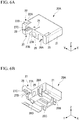
- Fig. 6A is a perspective view of the movable member as viewed from above.
- Fig. 6B is a perspective view of the movable member as viewed from below.
- the slider main body 20A of the movable member 20 includes a slider base 21 having a substantially rectangular shape in plan view.
- a clamper support portion 22 is formed at a left end on an upper surface side of the slider base 21.
- the clamper support portion 22 includes a recess 22A formed by cutting out a left end of the slider base 21 and a clamper shaft member 22B connecting a front wall and a rear wall of the recess 22A.
- the clamper shaft member 22B is disposed in the front-rear direction (extending direction of optical fiber).
- the slider lid 20B is rotatably attached to the clamper shaft member 22B.
- An optical fiber placing groove 24 is formed on the right side of the clamper support portion 22.
- the optical fiber placing groove 24 is a groove formed on an upper surface of the slider base 21 in the front-rear direction.
- the optical fiber placing groove 24 is a groove in which the optical fiber 2 to be cut is placed, and has a substantially V-shaped cross section.
- a clamper receiving portion 25 is formed on the right side of the optical fiber placing groove 24.
- the clamper receiving portion 25 is formed at a right end of the slider base 21.
- the clamper receiving portion 25 includes a clamper receiving recess and a locking plate formed on a right outer wall of the clamper receiving recess.
- the locking plate is a plate-like member formed so as to protrude inward from a right inner surface of the clamper receiving portion 25. An end of the slider lid 20B is held by such a locking plate to fix the slider lid 20B.
- engaging members 26A to 26D are disposed on a lower surface side of the slider base 21.
- Each of the engaging members 26A to 26D includes an elastic support portion extending in the up-down direction and an engaging portion attached to a lower end of the support portion, and is locked with the recess 13B formed on a lower surface side of the base member main body 11.
- each of the support portions of the engaging members 26A to 26D is integrally attached to the slider base 21.
- Each of the engaging portions of the engaging members 26A to 26D is formed so as to protrude outward from the support portion, and the protruding portion engages with the recess 13B formed on a lower surface side of the base member.
- a second locking portion 27 is disposed on a rear surface of the slider base 21.
- the second locking portion 27 includes a support block 27A and a second locking claw 27B formed on a lower surface of the support block 27A.
- a lower surface of the support block 27A is disposed at substantially the same height position as an upper surface of the support plate 15A in a state where the slider base 21 is assembled with the base member main body 11.
- the support block 27A is a block body long in the front-rear direction with a base end protruding rearward from the slider base 21.
- the second locking claw 27B is disposed on a lower surface of the support block 27A.
- the second locking claw 27B has a substantially triangular shape as viewed from a side, and has a front surface portion along the up-down direction and an inclined portion formed behind the front surface portion.
- a through hole 27C is formed at the central position of the support block 27A in the width direction (left-right direction).
- the through hole 27C passes through the support block 27A in the up-down direction.
- the through hole 27C is formed so as to be long in the front-rear direction.
- the second locking claw 27B is disposed on each of the left and right sides of the through hole 27C on a lower surface of the support block 27A.
- the unlocking receiving protrusion 15C of the first locking portion 15 is inserted into the through hole 27C from below.
- the height position of the unlocking receiving protrusion 15C is substantially the same as the height position of an upper surface of the support block 27A.
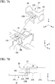
- Fig. 7A is an enlarged exploded perspective view of the vicinity of a locking member.
- Fig. 7B is a side view of the vicinity of the locking member.
- the second locking claw 27B is disposed at a position where the second locking claw 27B can be locked with the first locking claw 15B.
- the second locking claw 27B is disposed in front of the first locking claw 15B, the first locking claw 15B and the second locking claw 27B are not locked with each other, and the movable member 20 is in an unlocked state.
- the movable member 20 is at a retracted position, as indicated by a solid line in Fig.
- the second locking claw 27B is disposed behind the first locking claw 15B, the first locking claw 15B and the second locking claw 27B are locked with each other, and the movable member 20 is in a locked state in which the movable member 20 is locked and forward movement thereof is regulated.
- a stopper 28 is disposed at a rear end of the second locking portion 27.
- the stopper 28 is formed in a protrusion shape protruding upward at a rear end of the support block 27A.
- the stopper 28 regulates rotation of the initial cut forming member 40 when the movable member 20 is disposed in front of a retracted position and suppresses contact of the blade 45 with the optical fiber 2. Since the stopper 28 is disposed in the movable member 20, the stopper 28 is movable along with movement of the movable member 20.
- a spring housing hole 29 is formed in substantially the central portion of a rear surface portion of the slider base 21 in the left-right direction.
- the spring housing hole 29 is a recess having a circular cross section, and is disposed at a position facing the reaction wall 13C of the base member 10 when the movable member 20 is assembled with the base member 10.
- the spring housing hole 29 houses the spring 50.
- the movable member 20 includes the slider lid 20B in addition to the slider main body 20A.
- the slider lid 20B includes an elongated clamper main body 31.
- the clamper main body 31 is disposed in a clamping state in the left-right direction.
- a clamper grip 32 is disposed at a left end of the clamper main body 31 in a clamping state.
- the clamper grip 32 grips the clamper shaft member 22B of the movable member 20.
- the clamper grip 32 grips the clamper shaft member 22B, and the clamper main body 31 is thereby rotatable around the clamper shaft member 22B with respect to the slider base 21.
- the slider lid 20B changes into a clamping state or a non-clamping state.
- a holding member housing recess 33 is formed at substantially the central position of the clamper main body 31 in a longitudinal direction.
- the optical fiber holding member 34 is housed in the holding member housing recess 33.
- the optical fiber holding member 34 includes a case 34A.
- a holding member main body 34B is attached to a lower surface side of the case 34A.
- a pressing spring 34C is housed in the case 34A.
- the case 34A includes a locking claw.
- the locking claw is locked with a locking hole formed on an upper surface side of the holding member housing recess 33 of the clamper main body 31, and the optical fiber holding member 34 is thereby attached to the clamper main body 31.
- the holding member main body 34B is formed of an elastic member, for example, rubber, and comes into contact with the optical fiber 2 when the optical fiber 2 is clamped by the slider main body 20A and the slider lid 20B.
- the pressing spring 34C is a compression spring and biases the holding member main body 34B in a direction separating from an upper surface of the clamper main body 31.
- a clamper fixing member 35 is disposed at a right end of the clamper main body 31 in a clamping state.
- the clamper fixing member 35 includes a knob portion 35A and a locking portion 35B.
- the knob portion 35A has a shape in which a plate-like body is folded back around an axis along the X-axis, and a folded-back portion between an inner piece and an outer piece is elastic.
- the locking portion 35B is disposed on an outer surface of the outer piece.
- the clamper fixing member 35 can be housed in a clamper receiving recess of the clamper receiving portion 25 formed in the slider base 21.
- the inner piece and the outer piece of the knob portion 35A are separated from each other by an elastic force of a folded-back portion.
- a locking state in which the locking portion 35B of the clamper fixing member 35 is locked with the locking plate of the clamper receiving portion 25 is brought about.
- the slider lid 20B is fixed and brought into a clamping state in which the slider lid 20B clamps the optical fiber 2.
- the initial cut forming member 40 is attached to the rear of the slider mounter 13 of the base member main body 11. As shown in Figs. 1 to 3 , the initial cut forming member 40 includes an elongated cutter supporter 41.
- the cutter supporter 41 is disposed in the left-right direction in a state of being at an operating position.
- a cutter member grip 42 is disposed at a left end of the cutter supporter 41 at the operating position.
- the cutter member grip 42 grips the cutter shaft member 14C in the cutter supporter support 14 disposed in the base member main body 11.
- the cutter supporter 41 can rotate around the cutter shaft member 14C with respect to the base member main body 11. Therefore, the blade 45 attached to the cutter supporter 41 is movable in a direction intersecting with the extending direction of the optical fiber 2 (front-rear direction), for example, in a direction along a surface orthogonal to the optical fiber 2.
- the cutter supporter 41 has an unlocking protrusion 43.
- the unlocking protrusion 43 has a shape slightly smaller than the shape of the through hole 27C formed in the support block 27A. When the movable member 20 is disposed at a retracted position, the unlocking protrusion 43 can enter the through hole 27C. When the movable member 20 is disposed at a retracted position, the unlocking protrusion 43 is in contact with the stopper 28 and cannot enter the through hole 27C.
- the unlocking protrusion 43 can enter the through hole 27C of the support block 27A from above.
- the unlocking protrusion 43 presses the unlocking receiving protrusion 15C from above and releases a locked state caused by the first locking claw 15B and the second locking claw 27B.
- the unlocking receiving protrusion 15C and the unlocking protrusion 43 constitute an unlocking member.
- a blade holder 44 is disposed outside the unlocking protrusion 43 of the cutter supporter 41, and the blade 45 is held by the blade holder 44.
- the blade holder 44 is disposed on a lower surface side of the cutter supporter 41 at an operating position.
- a blade insertion hole 46 is formed at a position where the blade holder 44 is disposed in the cutter supporter 41.
- the blade 45 is press-fitted into the blade insertion hole 46, attached to the cutter supporter 41, and held by the blade holder 44.
- the blade 45 when the initial cut forming member 40 is at an operating position, a blade tip is formed at a front end thereof, and the rear thereof is tapered.
- the blade insertion hole 46 into which the blade 45 is press-fitted is formed in a direction inclined with respect to an extending direction of the cutter supporter 41. Since the blade 45 is press-fitted along the blade insertion hole 46, the blade tip of the blade 45 is along a direction inclined with respect to the extending direction of the cutter supporter 41.
- the extending direction of the cutter supporter 41 is along the width direction (left-right direction) when the initial cut forming member 40 is at an operating position. Therefore, when the initial cut forming member 40 is at an operating position, the blade 45 faces a direction inclined with respect to the width direction (left-right direction).
- a fitting protrusion 47 serving as a height position regulator is disposed on a lower side surface in the vicinity of a right end of the cutter supporter 41 at an operating position.
- the fitting protrusion 47 has substantially the same width as a separation distance of the pair of columnar bodies in the cutter supporter receiving portion 18 formed in the base member main body 11.
- the fitting protrusion 47 is fitted with the cutter supporter receiving portion 18 when the initial cut forming member 40 is at an operating position or a position close to the operating position.
- the fitting protrusion 47 disposed in the cutter supporter 41 and the cutter supporter receiving portion 18 disposed in the base member main body 11 guide movement of the cutter supporter 41 when the blade 45 is in contact with the optical fiber 2.
- the height position of the blade 45 is regulated to the height position of the optical fiber 2 when the cutter supporter 41 is moved.
- a handle 48 is disposed at a right end of the cutter supporter 41 at an operating position.
- a fiber placing base 17 on which the optical fiber 2 is placed can also be disposed at the rear of the optical fiber positioning member 16 of the base member 10 and below the blade 45 at an initial cut forming position.
- the fiber placing base 17 can be attached to the base member main body 11 by screwing a screw inserted into a screw insertion hole 17A.
- the fiber placing base 17 can be attached to and detached from the base member main body 11 by screwing in or removing a screw.
- the spring 50 housed in the spring housing hole 29 of the movable member 20 is a compression spring.
- the length of the spring 50 is longer than a distance between a back wall surface of the spring housing hole 29 and the reaction wall 13C disposed in the base member main body 11 when the movable member 20 is at a retracted position. Therefore, the spring 50 biases the movable member 20 at a retracted position forward.
- the fiber holder 70 can be disposed in the fiber holder disposing portion 19 of the base member main body 11. When the optical fiber 2 is cut, the fiber holder 70 holding the optical fiber 2 in an extension state is disposed in the fiber holder disposing portion 19.
- FIGs. 8A to 8C are explanatory views schematically showing a step of cutting an optical fiber.
- the fiber holder 70 holding the optical fiber 2 in an extension state is placed on the fiber holder disposing portion 19 of the base member main body 11.
- the movable member 20 is disposed at an advanced position.
- the slider lid 20B is in a non-clamping state, and the initial cut forming member 40 is disposed at a non-acting position.
- the movable member 20 is moved to a retracted position.
- the first locking claw 15B disposed in the base member main body 11 and the second locking claw 27B disposed in the slider base 21 are locked with each other to regulate forward movement of the movable member 20.
- the movable member 20 is locked.
- the slider lid 20B in a non-clamping state is rotated around the clamper shaft member 22B to bring the slider lid 20B into a clamping state from the non-clamping state.
- the slider lid 20B clamps the optical fiber 2.
- the initial cut forming member 40 in a non-operating position is rotated around the cutter shaft member 14C and moved from the non-operating position to an operating position.
- the unlocking protrusion 43 disposed in the cutter supporter 41 presses the unlocking receiving protrusion 15C disposed in the first locking portion 15.
- the first locking portion 15 is pushed down by the unlocking protrusion 43, the locked state between the first locking claw 15B and the second locking claw 27B is released, and regulation of forward movement of the movable member 20 is released.
- the spring 50 which is a compression spring is housed in the spring housing hole 29 of the movable member 20.
- the spring 50 obtains a reaction from the reaction wall 13C of the base member 10 to bias the movable member 20 forward. Therefore, a forward moving force acts on the movable member 20.
- the slider lid 20B disposed in the movable member 20 clamps the optical fiber 2. Therefore, the movable member 20 keeps stopping without moving forward. At this time, tension is applied to the optical fiber 2 by a biasing force of the spring 50.
- the blade 45 of the initial cut forming member 40 reaches the optical fiber 2, and the blade 45 forms an initial cut in the optical fiber 2.
- the optical fiber 2 is cleaved from a portion where the initial cut is formed and cut. In this way, the work of cutting the optical fiber 2 is completed.
- Fig. 9 is an explanatory view schematically showing a step of releasing a locking member.
- the initial cut forming member 40 is rotated around the cutter shaft member 14C while the movable member 20 is in a locked state, as shown in the portion (A-1) of Fig. 9 , the unlocking protrusion 43 moves toward the unlocking receiving protrusion 15C.
- the first locking claw 15B and the second locking claw 27B are locked with each other.
- the blade 45 is in a state before reaching the optical fiber 2.
- the unlocking protrusion 43 presses the unlocking receiving protrusion 15C downward.
- the unlocking receiving protrusion 15C is inserted from below into the through hole 27C formed in the support block 27A of the second locking portion 27.
- the unlocking protrusion 43 having a size slightly smaller than the through hole 27C can enter the through hole 27C. Therefore, by rotating the initial cut forming member 40, the unlocking protrusion 43 enters the through hole 27C to surely come into contact with the unlocking receiving protrusion 15C.
- the unlocking protrusion 43 can surely press the unlocking receiving protrusion 15C.
- a forward biasing force is applied to the slider base 21 by the spring 50.
- the slider main body 20A and the slider lid 20B clamp the optical fiber 2, and forward movement of the slider base 21 is thereby limited.
- tension by a biasing force of the spring 50 is applied to the optical fiber 2.
- the initial cut forming member 40 is rotated from an operating position to a non-operating position.
- the unlocking protrusion 43 is pulled out from the through hole 27C formed in the support block 27A.
- the slider base 21 further advances by a biasing force of the spring 50 and moves to an advanced position.
- the stopper 28 suppresses movement of the initial cut forming member 40 to the operating position and further suppresses movement thereof to the acting position.
- the optical fiber cutter 1 As described above, in the optical fiber cutter 1, after the movable member 20 is moved to the retracted position, forward movement of the movable member 20 is regulated by the locking member, and the slider main body 20A and the slider lid 20B clamp the optical fiber 2. Thereafter, when the initial cut forming member 40 is rotated, first, regulation of forward movement of the movable member 20 by the locking member is released, and tension is applied to the optical fiber 2. Subsequently, when the initial cut forming member 40 is further rotated, the blade 45 comes into contact with the optical fiber 2. Therefore, it is possible to simplify the work up to cutting an optical fiber, and it is possible to cut the optical fiber without making a mistake in procedures of work.
- the work of forming an initial cut in the optical fiber 2 is performed by bringing the blade 45 into contact with the optical fiber 2. Therefore, when the work of forming an initial cut in the optical fiber 2 by the blade 45 is repeated, the blade 45 is worn out by the contact with the optical fiber 2.
- the initial cut forming member 40 repeats similar rotating operations. Therefore, wear of the blade 45 at a predetermined contact position proceeds. Finally, the initial cut forming ability of forming an initial cut in the optical fiber 2 at the contact position is lost.
- the cutter supporter 41 is assumed to move in the up-down direction.
- the contact position of the blade 45 with the optical fiber 2 is constant. Therefore, contact of the blade 45 with the optical fiber 2 at a position where initial cut forming ability is lost cannot be avoided, and the optical fiber 2 cannot be cut.
- the contact position of the blade 45 with the optical fiber 2 loses initial cut forming ability
- the contact position with the optical fiber 2 sequentially moves in the width direction of the blade 45. Therefore, even if the contact position of the blade 45 loses initial cut forming ability, the contact position is updated to a new position. Therefore, it is possible to contribute to lengthening the usable period of the blade 45.
- the locking member includes the first locking claw 15B of the first locking portion 15 and the second locking claw 27B of the second locking portion 27. Therefore, it is possible to regulate movement of the movable member 20 with a simple configuration.
- the unlocking member includes the unlocking receiving protrusion 15C disposed in the first locking portion 15 and the unlocking protrusion 43 disposed in the cutter supporter 41. Therefore, by only rotating the initial cut forming member 40, it is possible to easily release a locked state between the first locking claw 15B and the second locking claw 27B.
- the fitting protrusion 47 is formed at a tip of the cutter supporter 41 of the initial cut forming member 40.
- the fitting protrusion 47 can be fitted with the cutter supporter receiving portion 18 disposed in the base member main body 11.
- the height position of the blade 45 is regulated to the height position of the optical fiber 2 when the cutter supporter 41 is moved. Therefore, it is possible to suitably set a distance between the blade 45 and the optical fiber 2 when an initial cut is formed in the optical fiber 2.
Landscapes
- Physics & Mathematics (AREA)
- General Physics & Mathematics (AREA)
- Optics & Photonics (AREA)
- Chemical & Material Sciences (AREA)
- Crystallography & Structural Chemistry (AREA)
- Light Guides In General And Applications Therefor (AREA)
Abstract
Description
- The present disclosure relates to an optical fiber cutter.
- The present application claims priority based on Japanese Patent Application No.
2016-227163 filed on November 22, 2016 - For example, when an optical fiber is cut, a fiber cutter forms an initial cut in the optical fiber in a state in which tension is applied to the optical fiber, grows the initial cut by the tension applied to the optical fiber, and cuts the optical fiber by cleavage (see, for example, Patent Document 1). Such a fiber cutter holds an optical fiber by a first optical fiber holder and a second optical fiber holder in a state in which tension is applied between the first optical fiber holder and the second optical fiber holder. Subsequently, an initial cut is formed between the first optical fiber holder and the second optical fiber holder. Then, the initial cut in the optical fiber grows due to tension between the first optical fiber holder and the second optical fiber holder, and the optical fiber is cut by cleavage.
- [Patent Document 1]
Japanese Unexamined Patent Application, First Publication No.2014-238574 - In the above-described conventional fiber cutter, as work of cutting an optical fiber, it is necessary to perform work of holding the optical fiber by the first optical fiber holder and the second optical fiber holder, applying tension to the optical fiber (operation of a tension applying mechanism or the like), and moving the cutter to form an initial cut in the optical fiber. Therefore, the work of cutting an optical fiber is complicated and there is a possibility of making a mistake in procedures thereof.
- The present invention has been made in view of the above circumstances, and provides an optical fiber cutter capable of cutting an optical fiber without making a mistake in procedures of work.
- A first aspect of the present invention is an optical fiber cutter which cuts an optical fiber held by a fiber holder in an extension state, the optical fiber cutter including, a base member, a movable member which clamps the optical fiber extending from the fiber holder and is movable with respect to the base member between an advanced position and a retracted position in an extending direction of the optical fiber, a biasing member which biases the movable member at the retracted position forward, a locking member which regulates forward movement of the movable member at the retracted position, a cutter supporter which supports a blade capable of forming an initial cut in the optical fiber, is moved in a direction intersecting with the extending direction of the optical fiber, and forms the initial cut by the blade at an initial cut forming position between the fiber holder and the movable member in the optical fiber, and an unlocking member which, when the cutter supporter is moved, releases the regulation of forward movement of the movable member by the locking member before the blade reaches the initial cut forming position.
- The above configuration includes the unlocking member which, when the cutter supporter is moved, releases the regulation of forward movement of the movable member before the blade reaches the initial cut forming position. Therefore, when the cutter supporter is moved, locking by the locking member is first released, tension is applied to the optical fiber, and then the blade comes into contact with the optical fiber. Therefore, it is possible to simplify work up to cutting the optical fiber, and it is possible to cut the optical fiber without making a mistake in procedures of work.
- A second aspect of the present invention is the optical fiber cutter according to the first aspect, in which the optical fiber cutter may further include a stopper which limits contact of the blade with the optical fiber when the movable member is in front of the retracted position.
- According to the above configuration, when the movable member is in front of the retracted position, contact of the blade with the optical fiber is limited. Therefore, it is possible to suppress formation of an initial cut in a state where tension is not applied to the optical fiber.
- A third aspect of the present invention is the optical fiber cutter according to the second aspect, in which the stopper may be movable along with movement of the movable member.
- According to the above configuration, the stopper can be operated by disposing the movable member in front of the retracted position.
- A fourth aspect of the present invention is the optical fiber cutter according to any one of the first to third aspects, in which the cutter supporter may be rotatable around an axis in an extending direction of the optical fiber.
- According to the above configuration, it is possible to contribute to lengthening a usable period of the blade.
- A fifth aspect of the present invention is the optical fiber cutter according to any one of the first to fourth aspects, in which the locking member may include a first locking portion disposed in the base member and a second locking portion disposed in the fiber holder, the first locking portion and the second locking portion may be locked with each other to regulate forward movement of the movable member, and the unlocking member may press at least one of the first locking portion and the second locking portion along with movement of the cutter supporter to release locking between the first locking portion and the second locking portion.
- According to the above configuration, it is possible to omit operation of releasing the locking member with simple operation.
- A sixth aspect of the present invention is the optical fiber cutter according to any one of the first to fifth aspects, in which the optical fiber cutter may include a height position regulator which regulates a height position when the blade is in contact with the optical fiber.
- According to the above configuration, it is possible to suitably set a distance between the blade and the optical fiber when an initial cut is formed in the optical fiber.
- The optical fiber cutter according to any one of the aspects of the present invention can cut an optical fiber without making a mistake in procedures of work.
-
-
Fig. 1 is a perspective view of an optical fiber cutter according to an embodiment of the present invention. -
Fig. 2 is an exploded perspective view of the optical fiber cutter according to the embodiment of the present invention. -
Fig. 3 is a rear view of the optical fiber cutter according to the embodiment of the present invention. -
Fig. 4 is a top view of a base member. -
Fig. 5 is a bottom view of the base member. -
Fig. 6A is a perspective view of a movable member as viewed from above. -
Fig. 6B is a perspective view of the movable member as viewed from below. -
Fig. 7A is an enlarged exploded perspective view of the vicinity of a locking member. -
Fig. 7B is a side view of the vicinity of the locking member. -
Fig. 8A is a view schematically showing a step of cutting an optical fiber. -
Fig. 8B is a view schematically showing a step of cutting an optical fiber. -
Fig. 8C is a view schematically showing a step of cutting an optical fiber. -
Fig. 9 is a view schematically showing a step of releasing a locking member. - Next, embodiments according to the present invention will be described based on the drawings.
-
Fig. 1 is a perspective view of an optical fiber cutter according to some embodiments of the present invention.Fig. 2 is an exploded perspective view thereof.Fig. 3 is a rear view thereof. Incidentally, in the following description, in order to make the invention easily understood, the drawings may sometimes be simplified by appropriately omitting some components, simplifying the shapes, changing the sizes, and the like. A positional relationship among the components will be described by setting an XYZ-orthogonal coordinate system. A description will be provided assuming that, in the XYZ-orthogonal coordinate system, the X direction is a front-rear direction, the Y direction is a left-right direction, and a Z direction is an up-down direction. A description will be provided assuming that the +X side is the front side, the -X side is the rear side, the +Y side is the left side, the -Y side is the right side, the +Z side is the upper side, and the -X side is the lower side. Note that the extending direction of the optical fiber is a direction along the X axis. - As shown in
Figs. 1 to 3 , anoptical fiber cutter 1 according to some embodiments of the present invention includes abase member 10 and amovable member 20. Themovable member 20 includes a slidermain body 20A and aslider lid 20B. As shown inFig. 2 , an opticalfiber holding member 34 is attached to theslider lid 20B. - An initial
cut forming member 40 is disposed at the rear of themovable member 20. Ablade 45 is attached to the initialcut forming member 40. Furthermore, aspring 50 as a biasing member is disposed between a rear end of themovable member 20 and thebase member 10. Afiber holder 70 holding theoptical fiber 2 is placed on thebase member 10 at the rear of the initialcut forming member 40 of thebase member 10. Incidentally, inFigs. 2 and3 , illustration of thefiber holder 70 is omitted. - The
slider lid 20B is brought into a clamping state in which theoptical fiber 2 is clamped as indicated by an imaginary line inFig. 1 , and into a non-clamping state in which clamping of theoptical fiber 2 is released as indicated by a solid line inFig. 1 When theslider lid 20B is brought into a clamping state, the slidermain body 20A and theslider lid 20B clamp theoptical fiber 2. The initialcut forming member 40 may be located at an acting position where theblade 45 disposed in the initialcut forming member 40 reaches an initial cut forming position where an initial cut is formed in theoptical fiber 2 as indicated by an imaginary line inFig. 1 , or may be located at a non-acting position other than the acting position as indicated by a solid line inFig. 1 . Theblade 45 can form an initial cut between thefiber holder 70 and themovable member 20 in theoptical fiber 2. - The
movable member 20 is movable in the front-rear direction with respect to thebase member 10 between an advanced position and a retracted position. Theslider lid 20B is attached to a left end of themovable member 20 and is rotatable around an axis in a moving direction of themovable member 20. The initialcut forming member 40 is attached to a left end of thebase member 10 and is rotatable around an axis in the moving direction of themovable member 20. - Next, the base member will be described.
Fig. 4 is a top view of the base member.Fig. 5 is a bottom view of the base member. As shown inFigs. 4 and 5 , thebase member 10 includes a base membermain body 11 having a substantially rectangular shape as a whole in plan view. Aslider mounter 13 is formed at substantially the central portion of the base membermain body 11 in the front-rear direction. Theslider mounter 13 includes a throughportion 13A passing through the base membermain body 11 in the up-down direction and arecess 13B formed on a lower surface side of the base membermain body 11 and having a slightly larger size than the throughportion 13A as viewed from below as shown inFig. 4 . Areaction wall 13C that applies reaction to thespring 50 is formed on a lower surface side of a rear inner wall of theslider mounter 13. - A
cutter supporter support 14 is formed at a rear left end of theslider mounter 13 of the base membermain body 11. Thecutter supporter support 14 includes a pair ofbrackets main body 11. Acutter shaft member 14C is stretched between thebrackets cutter shaft member 14C is disposed in the left-right direction (extending direction of optical fiber). The initialcut forming member 40 is rotatably attached to thecutter shaft member 14C. - A
first locking portion 15 is formed on the right side of a position where thecutter supporter support 14 is disposed in the base membermain body 11. Thefirst locking portion 15 includes asupport plate 15A, afirst locking claw 15B disposed at a tip of thesupport plate 15A, and an unlockingreceiving protrusion 15C. - The
support plate 15A is an elastically deformable plate-like body having a base end protruding forward from the base membermain body 11. Thesupport plate 15A shown in the drawing is formed integrally with the plastic base membermain body 11. However, thesupport plate 15A may be a member separate from the base membermain body 11 fixed to the base membermain body 11. Thefirst locking claw 15B is disposed on an upper surface at a tip of thesupport plate 15A. Thefirst locking claw 15B has a substantially triangular shape when viewed from a side, and has a rear surface portion along the up-down direction and an inclined portion formed in front of the rear surface portion. - The unlocking
receiving protrusion 15C is a rod-like member disposed at substantially the central position of thefirst locking claw 15B in the width direction (left-right direction) and extending to a position higher than thefirst locking claw 15B in the up-down direction. When the unlocking receivingprotrusion 15C is pressed from above, thesupport plate 15A is bent with the base end fixed to the base membermain body 11 as a base point. Thefirst locking portion 15 is disposed in the base membermain body 11, and thefiber holder 70 is disposed in a fiberholder disposing portion 19 of the base membermain body 11. Therefore, thefirst locking portion 15 is not movable relatively with respect to thefiber holder 70. - An optical
fiber positioning member 16 is formed on the right side of a position where thefirst locking portion 15 is formed in the base membermain body 11. As shown inFig. 2 , the opticalfiber positioning member 16 includes a plate-like body 16A erected from the base membermain body 11 in the up-down direction.A V groove 16B is formed in the plate-like body 16A. When theoptical fiber 2 is cut, theoptical fiber 2 is housed in a bottom of theV groove 16B to position theoptical fiber 2. - A cutter
supporter receiving portion 18 is disposed on the right side of the opticalfiber positioning member 16. The cuttersupporter receiving portion 18 is disposed at a right end of the base membermain body 11, and includes a pair of columnar bodies. The cuttersupporter receiving portion 18 guides movement of the initialcut forming member 40 at a position close to an operating position. - The fiber
holder disposing portion 19 is formed at the rear of the opticalfiber positioning member 16. The fiberholder disposing portion 19 is a recess in which thefiber holder 70 holding theoptical fiber 2 shown inFig. 1 can be disposed. Thefiber holder 70 is disposed in the fiberholder disposing portion 19, and thereby positioned and placed with respect to the base membermain body 11. - Next, the slider
main body 20A of themovable member 20 will be described. The slidermain body 20A of themovable member 20 is mounted on theslider mounter 13 formed in the base membermain body 11. The length of the throughportion 13A of theslider mounter 13 formed in the base membermain body 11 in the front-rear direction is longer than the length of the slidermain body 20A in the front-rear direction. Therefore, the slidermain body 20A can slide between an advanced position and a retracted position in the throughportion 13A of the base membermain body 11. Theslider mounter 13 of thebase member 10 serves as a guide portion that guides the slidermain body 20A slidably in the front-rear direction. The entiremovable member 20 moves in the front-rear direction with respect to thebase member 10 along with slide movement of the slidermain body 20A with respect to thebase member 10 in the front-rear direction. -
Fig. 6A is a perspective view of the movable member as viewed from above.Fig. 6B is a perspective view of the movable member as viewed from below. As shown inFigs. 6A and 6B , the slidermain body 20A of themovable member 20 includes aslider base 21 having a substantially rectangular shape in plan view. Aclamper support portion 22 is formed at a left end on an upper surface side of theslider base 21. Theclamper support portion 22 includes arecess 22A formed by cutting out a left end of theslider base 21 and aclamper shaft member 22B connecting a front wall and a rear wall of therecess 22A. Theclamper shaft member 22B is disposed in the front-rear direction (extending direction of optical fiber). Theslider lid 20B is rotatably attached to theclamper shaft member 22B. - An optical
fiber placing groove 24 is formed on the right side of theclamper support portion 22. The opticalfiber placing groove 24 is a groove formed on an upper surface of theslider base 21 in the front-rear direction. The opticalfiber placing groove 24 is a groove in which theoptical fiber 2 to be cut is placed, and has a substantially V-shaped cross section. - A
clamper receiving portion 25 is formed on the right side of the opticalfiber placing groove 24. Theclamper receiving portion 25 is formed at a right end of theslider base 21. Theclamper receiving portion 25 includes a clamper receiving recess and a locking plate formed on a right outer wall of the clamper receiving recess. The locking plate is a plate-like member formed so as to protrude inward from a right inner surface of theclamper receiving portion 25. An end of theslider lid 20B is held by such a locking plate to fix theslider lid 20B. - As shown in
Fig. 6B , engagingmembers 26A to 26D are disposed on a lower surface side of theslider base 21. Each of the engagingmembers 26A to 26D includes an elastic support portion extending in the up-down direction and an engaging portion attached to a lower end of the support portion, and is locked with therecess 13B formed on a lower surface side of the base membermain body 11. - An upper end of each of the support portions of the engaging
members 26A to 26D is integrally attached to theslider base 21. Each of the engaging portions of the engagingmembers 26A to 26D is formed so as to protrude outward from the support portion, and the protruding portion engages with therecess 13B formed on a lower surface side of the base member. When themovable member 20 moves, the engagingmembers 26A to 26D disposed in theslider base 21 move along therecess 13B formed in the base membermain body 11, and themovable member 20 thereby moves in the front-rear direction. - A
second locking portion 27 is disposed on a rear surface of theslider base 21. Thesecond locking portion 27 includes asupport block 27A and asecond locking claw 27B formed on a lower surface of thesupport block 27A. A lower surface of thesupport block 27A is disposed at substantially the same height position as an upper surface of thesupport plate 15A in a state where theslider base 21 is assembled with the base membermain body 11. - The
support block 27A is a block body long in the front-rear direction with a base end protruding rearward from theslider base 21. Thesecond locking claw 27B is disposed on a lower surface of thesupport block 27A. Thesecond locking claw 27B has a substantially triangular shape as viewed from a side, and has a front surface portion along the up-down direction and an inclined portion formed behind the front surface portion. - A through
hole 27C is formed at the central position of thesupport block 27A in the width direction (left-right direction). The throughhole 27C passes through thesupport block 27A in the up-down direction. The throughhole 27C is formed so as to be long in the front-rear direction. Thesecond locking claw 27B is disposed on each of the left and right sides of the throughhole 27C on a lower surface of thesupport block 27A. The unlockingreceiving protrusion 15C of thefirst locking portion 15 is inserted into the throughhole 27C from below. The height position of the unlocking receivingprotrusion 15C is substantially the same as the height position of an upper surface of thesupport block 27A. -
Fig. 7A is an enlarged exploded perspective view of the vicinity of a locking member.Fig. 7B is a side view of the vicinity of the locking member. As shown inFig. 7A , thesecond locking claw 27B is disposed at a position where thesecond locking claw 27B can be locked with thefirst locking claw 15B. When themovable member 20 is at an advanced position, as indicated by an imaginary line inFig. 7B , thesecond locking claw 27B is disposed in front of thefirst locking claw 15B, thefirst locking claw 15B and thesecond locking claw 27B are not locked with each other, and themovable member 20 is in an unlocked state. When themovable member 20 is at a retracted position, as indicated by a solid line inFig. 7B , thesecond locking claw 27B is disposed behind thefirst locking claw 15B, thefirst locking claw 15B and thesecond locking claw 27B are locked with each other, and themovable member 20 is in a locked state in which themovable member 20 is locked and forward movement thereof is regulated. - A
stopper 28 is disposed at a rear end of thesecond locking portion 27. Thestopper 28 is formed in a protrusion shape protruding upward at a rear end of thesupport block 27A. Thestopper 28 regulates rotation of the initialcut forming member 40 when themovable member 20 is disposed in front of a retracted position and suppresses contact of theblade 45 with theoptical fiber 2. Since thestopper 28 is disposed in themovable member 20, thestopper 28 is movable along with movement of themovable member 20. - As shown in
Figs. 6A and 6B , aspring housing hole 29 is formed in substantially the central portion of a rear surface portion of theslider base 21 in the left-right direction. Thespring housing hole 29 is a recess having a circular cross section, and is disposed at a position facing thereaction wall 13C of thebase member 10 when themovable member 20 is assembled with thebase member 10. Thespring housing hole 29 houses thespring 50. - As shown in
Fig. 1 , themovable member 20 includes theslider lid 20B in addition to the slidermain body 20A. As shown inFigs. 1 and2 , theslider lid 20B includes an elongated clampermain body 31. The clampermain body 31 is disposed in a clamping state in the left-right direction. Aclamper grip 32 is disposed at a left end of the clampermain body 31 in a clamping state. Theclamper grip 32 grips theclamper shaft member 22B of themovable member 20. Theclamper grip 32 grips theclamper shaft member 22B, and the clampermain body 31 is thereby rotatable around theclamper shaft member 22B with respect to theslider base 21. When the clampermain body 31 rotates around theclamper shaft member 22B, theslider lid 20B changes into a clamping state or a non-clamping state. - A holding
member housing recess 33 is formed at substantially the central position of the clampermain body 31 in a longitudinal direction. The opticalfiber holding member 34 is housed in the holdingmember housing recess 33. The opticalfiber holding member 34 includes acase 34A. A holding membermain body 34B is attached to a lower surface side of thecase 34A. Apressing spring 34C is housed in thecase 34A. - The
case 34A includes a locking claw. The locking claw is locked with a locking hole formed on an upper surface side of the holdingmember housing recess 33 of the clampermain body 31, and the opticalfiber holding member 34 is thereby attached to the clampermain body 31. The holding membermain body 34B is formed of an elastic member, for example, rubber, and comes into contact with theoptical fiber 2 when theoptical fiber 2 is clamped by the slidermain body 20A and theslider lid 20B. Thepressing spring 34C is a compression spring and biases the holding membermain body 34B in a direction separating from an upper surface of the clampermain body 31. - A
clamper fixing member 35 is disposed at a right end of the clampermain body 31 in a clamping state. Theclamper fixing member 35 includes aknob portion 35A and a lockingportion 35B. Theknob portion 35A has a shape in which a plate-like body is folded back around an axis along the X-axis, and a folded-back portion between an inner piece and an outer piece is elastic. The lockingportion 35B is disposed on an outer surface of the outer piece. - The
clamper fixing member 35 can be housed in a clamper receiving recess of theclamper receiving portion 25 formed in theslider base 21. When theclamper fixing member 35 is housed in the clamper receiving recess, the inner piece and the outer piece of theknob portion 35A are separated from each other by an elastic force of a folded-back portion. When the inner piece and the outer piece of theknob portion 35A are separated from each other, a locking state in which the lockingportion 35B of theclamper fixing member 35 is locked with the locking plate of theclamper receiving portion 25 is brought about. Theslider lid 20B is fixed and brought into a clamping state in which theslider lid 20B clamps theoptical fiber 2. - When a worker or the like pinches the
knob portion 35A, the inner piece and the outer piece of theknob portion 35A come close to each other, and a locking state between the lockingportion 35B of theclamper fixing member 35 and the locking plate of theclamper receiving portion 25 is released. At this time, by pulling up theknob portion 35A while pinching theknob portion 35A, the clampermain body 31 rotates, the clamping state of theslider lid 20B is released, and theslider lid 20B is brought into a non-clamping state. - As shown in
Fig. 1 , the initialcut forming member 40 is attached to the rear of theslider mounter 13 of the base membermain body 11. As shown inFigs. 1 to 3 , the initialcut forming member 40 includes anelongated cutter supporter 41. Thecutter supporter 41 is disposed in the left-right direction in a state of being at an operating position. - A
cutter member grip 42 is disposed at a left end of thecutter supporter 41 at the operating position. Thecutter member grip 42 grips thecutter shaft member 14C in thecutter supporter support 14 disposed in the base membermain body 11. By gripping of thecutter shaft member 14C by thecutter member grip 42, thecutter supporter 41 can rotate around thecutter shaft member 14C with respect to the base membermain body 11. Therefore, theblade 45 attached to thecutter supporter 41 is movable in a direction intersecting with the extending direction of the optical fiber 2 (front-rear direction), for example, in a direction along a surface orthogonal to theoptical fiber 2. - The
cutter supporter 41 has an unlockingprotrusion 43. The unlockingprotrusion 43 has a shape slightly smaller than the shape of the throughhole 27C formed in thesupport block 27A. When themovable member 20 is disposed at a retracted position, the unlockingprotrusion 43 can enter the throughhole 27C. When themovable member 20 is disposed at a retracted position, the unlockingprotrusion 43 is in contact with thestopper 28 and cannot enter the throughhole 27C. - The unlocking
protrusion 43 can enter the throughhole 27C of thesupport block 27A from above. When the unlockingprotrusion 43 enters the throughhole 27C of thesupport block 27A, the unlockingprotrusion 43 presses the unlocking receivingprotrusion 15C from above and releases a locked state caused by thefirst locking claw 15B and thesecond locking claw 27B. The unlockingreceiving protrusion 15C and the unlockingprotrusion 43 constitute an unlocking member. - A
blade holder 44 is disposed outside the unlockingprotrusion 43 of thecutter supporter 41, and theblade 45 is held by theblade holder 44. Theblade holder 44 is disposed on a lower surface side of thecutter supporter 41 at an operating position. Ablade insertion hole 46 is formed at a position where theblade holder 44 is disposed in thecutter supporter 41. Theblade 45 is press-fitted into theblade insertion hole 46, attached to thecutter supporter 41, and held by theblade holder 44. - In the
blade 45, as shown inFig. 3 , when the initialcut forming member 40 is at an operating position, a blade tip is formed at a front end thereof, and the rear thereof is tapered. Theblade insertion hole 46 into which theblade 45 is press-fitted is formed in a direction inclined with respect to an extending direction of thecutter supporter 41. Since theblade 45 is press-fitted along theblade insertion hole 46, the blade tip of theblade 45 is along a direction inclined with respect to the extending direction of thecutter supporter 41. The extending direction of thecutter supporter 41 is along the width direction (left-right direction) when the initialcut forming member 40 is at an operating position. Therefore, when the initialcut forming member 40 is at an operating position, theblade 45 faces a direction inclined with respect to the width direction (left-right direction). - A
fitting protrusion 47 serving as a height position regulator is disposed on a lower side surface in the vicinity of a right end of thecutter supporter 41 at an operating position. Thefitting protrusion 47 has substantially the same width as a separation distance of the pair of columnar bodies in the cuttersupporter receiving portion 18 formed in the base membermain body 11. Thefitting protrusion 47 is fitted with the cuttersupporter receiving portion 18 when the initialcut forming member 40 is at an operating position or a position close to the operating position. Thefitting protrusion 47 disposed in thecutter supporter 41 and the cuttersupporter receiving portion 18 disposed in the base membermain body 11 guide movement of thecutter supporter 41 when theblade 45 is in contact with theoptical fiber 2. By fitting thefitting protrusion 47 with the cuttersupporter receiving portion 18, the height position of theblade 45 is regulated to the height position of theoptical fiber 2 when thecutter supporter 41 is moved. Ahandle 48 is disposed at a right end of thecutter supporter 41 at an operating position. Note that afiber placing base 17 on which theoptical fiber 2 is placed, indicated by an imaginary line inFig. 1 , can also be disposed at the rear of the opticalfiber positioning member 16 of thebase member 10 and below theblade 45 at an initial cut forming position. Thefiber placing base 17 can be attached to the base membermain body 11 by screwing a screw inserted into ascrew insertion hole 17A. Thefiber placing base 17 can be attached to and detached from the base membermain body 11 by screwing in or removing a screw. - The
spring 50 housed in thespring housing hole 29 of themovable member 20 is a compression spring. The length of thespring 50 is longer than a distance between a back wall surface of thespring housing hole 29 and thereaction wall 13C disposed in the base membermain body 11 when themovable member 20 is at a retracted position. Therefore, thespring 50 biases themovable member 20 at a retracted position forward. - The
fiber holder 70 can be disposed in the fiberholder disposing portion 19 of the base membermain body 11. When theoptical fiber 2 is cut, thefiber holder 70 holding theoptical fiber 2 in an extension state is disposed in the fiberholder disposing portion 19. - Next, a procedure for cutting the
optical fiber 2 by theoptical fiber cutter 1 will be described.Figs. 8A to 8C are explanatory views schematically showing a step of cutting an optical fiber. When theoptical fiber 2 is cut, first, thefiber holder 70 holding theoptical fiber 2 in an extension state is placed on the fiberholder disposing portion 19 of the base membermain body 11. At this time, themovable member 20 is disposed at an advanced position. In addition, theslider lid 20B is in a non-clamping state, and the initialcut forming member 40 is disposed at a non-acting position. - Next, as shown in
Fig. 8A , themovable member 20 is moved to a retracted position. Thefirst locking claw 15B disposed in the base membermain body 11 and thesecond locking claw 27B disposed in theslider base 21 are locked with each other to regulate forward movement of themovable member 20. In this way, themovable member 20 is locked. Subsequently, theslider lid 20B in a non-clamping state is rotated around theclamper shaft member 22B to bring theslider lid 20B into a clamping state from the non-clamping state. Theslider lid 20B clamps theoptical fiber 2. - After the
optical fiber 2 is clamped, as shown inFig. 8B , the initialcut forming member 40 in a non-operating position is rotated around thecutter shaft member 14C and moved from the non-operating position to an operating position. Before theblade 45 reaches theoptical fiber 2 in the process of moving the initialcut forming member 40 from the non-operating position to the operating position by rotating operation of the initialcut forming member 40, the unlockingprotrusion 43 disposed in thecutter supporter 41 presses the unlocking receivingprotrusion 15C disposed in thefirst locking portion 15. As a result, thefirst locking portion 15 is pushed down by the unlockingprotrusion 43, the locked state between thefirst locking claw 15B and thesecond locking claw 27B is released, and regulation of forward movement of themovable member 20 is released. - The
spring 50 which is a compression spring is housed in thespring housing hole 29 of themovable member 20. Thespring 50 obtains a reaction from thereaction wall 13C of thebase member 10 to bias themovable member 20 forward. Therefore, a forward moving force acts on themovable member 20. However, theslider lid 20B disposed in themovable member 20 clamps theoptical fiber 2. Therefore, themovable member 20 keeps stopping without moving forward. At this time, tension is applied to theoptical fiber 2 by a biasing force of thespring 50. - Subsequently, when the initial
cut forming member 40 is further rotated, as shown inFig. 8C , theblade 45 of the initialcut forming member 40 reaches theoptical fiber 2, and theblade 45 forms an initial cut in theoptical fiber 2. When the initial cut is formed in theoptical fiber 2 with the tension applied, theoptical fiber 2 is cleaved from a portion where the initial cut is formed and cut. In this way, the work of cutting theoptical fiber 2 is completed. - Among the steps in which the initial
cut forming member 40 is rotated, a step of releasing themovable member 20 from a locked state and cutting theoptical fiber 2 will be further described.Fig. 9 is an explanatory view schematically showing a step of releasing a locking member. When the initialcut forming member 40 is rotated around thecutter shaft member 14C while themovable member 20 is in a locked state, as shown in the portion (A-1) ofFig. 9 , the unlockingprotrusion 43 moves toward the unlocking receivingprotrusion 15C. At this time, thefirst locking claw 15B and thesecond locking claw 27B are locked with each other. As shown in the portion (B-1) ofFig. 9 , theblade 45 is in a state before reaching theoptical fiber 2. - Subsequently, when the initial
cut forming member 40 is further rotated, as shown in the portion (A-2) ofFig. 9 , the unlockingprotrusion 43 presses the unlocking receivingprotrusion 15C downward. The unlockingreceiving protrusion 15C is inserted from below into the throughhole 27C formed in thesupport block 27A of thesecond locking portion 27. The unlockingprotrusion 43 having a size slightly smaller than the throughhole 27C can enter the throughhole 27C. Therefore, by rotating the initialcut forming member 40, the unlockingprotrusion 43 enters the throughhole 27C to surely come into contact with the unlocking receivingprotrusion 15C. The unlockingprotrusion 43 can surely press the unlocking receivingprotrusion 15C. - Even if the unlocking
protrusion 43 presses the unlocking receivingprotrusion 15C and lowers the unlocking receivingprotrusion 15C to a position where thefirst locking claw 15B and thesecond locking claw 27B are released from a locked state, as shown in the portion (B-2) ofFig. 9 , theblade 45 is located at a position not reaching theoptical fiber 2. - A forward biasing force is applied to the
slider base 21 by thespring 50. However, as shown inFig. 8B , the slidermain body 20A and theslider lid 20B clamp theoptical fiber 2, and forward movement of theslider base 21 is thereby limited. In addition, tension by a biasing force of thespring 50 is applied to theoptical fiber 2. - Then, as shown in the portion (A-3) of
Fig. 9 , when the initialcut forming member 40 rotates, as shown in the portion (B-3) ofFig. 9 , theblade 45 comes into contact with theoptical fiber 2, and theoptical fiber 2 is cut by cleavage. At this time, since the tension of theoptical fiber 2 is released, theslider base 21 moves forward. Thereafter, the work of cutting theoptical fiber 2 is completed. The series of operations so far are performed only by rotating the initialcut forming member 40. - After the work of cutting the
optical fiber 2 is completed, the initialcut forming member 40 is rotated from an operating position to a non-operating position. In this process, the unlockingprotrusion 43 is pulled out from the throughhole 27C formed in thesupport block 27A. After the unlockingprotrusion 43 is pulled out, theslider base 21 further advances by a biasing force of thespring 50 and moves to an advanced position. When theslider base 21 moves to the advanced position, thestopper 28 suppresses movement of the initialcut forming member 40 to the operating position and further suppresses movement thereof to the acting position. - As described above, in the
optical fiber cutter 1, after themovable member 20 is moved to the retracted position, forward movement of themovable member 20 is regulated by the locking member, and the slidermain body 20A and theslider lid 20B clamp theoptical fiber 2. Thereafter, when the initialcut forming member 40 is rotated, first, regulation of forward movement of themovable member 20 by the locking member is released, and tension is applied to theoptical fiber 2. Subsequently, when the initialcut forming member 40 is further rotated, theblade 45 comes into contact with theoptical fiber 2. Therefore, it is possible to simplify the work up to cutting an optical fiber, and it is possible to cut the optical fiber without making a mistake in procedures of work. - When the
movable member 20 is disposed at the advanced position in front of the retracted position, rotation of the initialcut forming member 40 is blocked by thestopper 28. Therefore, theblade 45 can be prevented from coming into contact with theoptical fiber 2 when themovable member 20 is in the advanced position. Therefore, it is possible to suppress formation of an initial cut in a state where tension is not applied to theoptical fiber 2. In addition, by inclusion of thestopper 28 in themovable member 20, themovable member 20 is disposed at the advanced position, and thestopper 28 can be thereby operated. - The work of forming an initial cut in the
optical fiber 2 is performed by bringing theblade 45 into contact with theoptical fiber 2. Therefore, when the work of forming an initial cut in theoptical fiber 2 by theblade 45 is repeated, theblade 45 is worn out by the contact with theoptical fiber 2. When an initial cut is formed in theoptical fiber 2, the initialcut forming member 40 repeats similar rotating operations. Therefore, wear of theblade 45 at a predetermined contact position proceeds. Finally, the initial cut forming ability of forming an initial cut in theoptical fiber 2 at the contact position is lost. - Here, for example, the
cutter supporter 41 is assumed to move in the up-down direction. In this case, the contact position of theblade 45 with theoptical fiber 2 is constant. Therefore, contact of theblade 45 with theoptical fiber 2 at a position where initial cut forming ability is lost cannot be avoided, and theoptical fiber 2 cannot be cut. - Meanwhile, in the
optical fiber cutter 1, movement of the initialcut forming member 40 from a non-operating position to an operating position is performed by rotation of thecutter supporter 41 around thecutter shaft member 14C. Therefore, for example, even if the contact position of theblade 45 with theoptical fiber 2 is worn out and loses cutting ability, when thecutter supporter 41 is further rotated, the contact position of theblade 45 with theoptical fiber 2 slides in the width direction of theblade 45, and theoptical fiber 2 comes into contact with theblade 45 at a position where wear has not occurred. In this case, an initial cut can be formed in theoptical fiber 2 at a position where wear of theblade 45 has not proceeded. - As described above, even if the contact position of the
blade 45 with theoptical fiber 2 loses initial cut forming ability, the contact position with theoptical fiber 2 sequentially moves in the width direction of theblade 45. Therefore, even if the contact position of theblade 45 loses initial cut forming ability, the contact position is updated to a new position. Therefore, it is possible to contribute to lengthening the usable period of theblade 45. - The locking member includes the
first locking claw 15B of thefirst locking portion 15 and thesecond locking claw 27B of thesecond locking portion 27. Therefore, it is possible to regulate movement of themovable member 20 with a simple configuration. The unlocking member includes the unlocking receivingprotrusion 15C disposed in thefirst locking portion 15 and the unlockingprotrusion 43 disposed in thecutter supporter 41. Therefore, by only rotating the initialcut forming member 40, it is possible to easily release a locked state between thefirst locking claw 15B and thesecond locking claw 27B. - The
fitting protrusion 47 is formed at a tip of thecutter supporter 41 of the initialcut forming member 40. Thefitting protrusion 47 can be fitted with the cuttersupporter receiving portion 18 disposed in the base membermain body 11. By fitting thefitting protrusion 47 with the cuttersupporter receiving portion 18, the height position of theblade 45 is regulated to the height position of theoptical fiber 2 when thecutter supporter 41 is moved. Therefore, it is possible to suitably set a distance between theblade 45 and theoptical fiber 2 when an initial cut is formed in theoptical fiber 2. -
- 1:
- Optical fiber cutter
- 2:
- Optical fiber
- 10:
- Base member
- 11:
- Base member main body
- 13:
- Slider mounter
- 13C:
- Reaction wall
- 15:
- First locking portion
- 15A:
- Support plate
- 15B:
- First locking claw (locking member)
- 15C:
- Unlocking receiving protrusion (unlocking member)
- 18:
- Cutter supporter receiving portion
- 19:
- Fiber holder disposing portion
- 20:
- Movable member
- 20A:
- Slider main body
- 20B:
- Slider lid
- 27:
- Second locking portion
- 27A:
- Support block
- 27B:
- Second locking claw (locking member)
- 27C:
- Through hole
- 28:
- Stopper
- 40:
- Initial cut forming member
- 41:
- Cutter supporter
- 43:
- Unlocking protrusion (unlocking member)
- 45:
- Blade
- 46:
- Blade insertion hole
- 47:
- Fitting protrusion (height position regulator)
- 50:
- Spring (biasing member)
- 70:
- Fiber holder
Claims (6)
- An optical fiber cutter which cuts an optical fiber held by a fiber holder in an extension state, the optical fiber cutter comprising:a base member;a movable member which clamps the optical fiber extending from the fiber holder and is movable with respect to the base member between an advanced position and a retracted position in an extending direction of the optical fiber;a biasing member which biases the movable member at the retracted position forward;a locking member which regulates forward movement of the movable member at the retracted position;a cutter supporter which supports a blade capable of forming an initial cut in the optical fiber, is moved in a direction intersecting with the extending direction of the optical fiber, and forms the initial cut by the blade at an initial cut forming position between the fiber holder and the movable member in the optical fiber; andan unlocking member which, when the cutter supporter is moved, releases the regulation of forward movement of the movable member by the locking member before the blade reaches the initial cut forming position.
- The optical fiber cutter according to claim 1, further comprising a stopper which limits contact of the blade with the optical fiber when the movable member is in front of the retracted position.
- The optical fiber cutter according to claim 2, wherein the stopper is movable along with movement of the movable member.
- The optical fiber cutter according to any one of claims 1 to 3, wherein the cutter supporter is rotatable around an axis along an extending direction of the optical fiber.
- The optical fiber cutter according to any one of claims 1 to 4, wherein
the locking member includes: a first locking portion disposed in the base member; and a second locking portion disposed in the movable member, and the first locking portion and the second locking portion are locked with each other to regulate forward movement of the movable member, and
the unlocking member presses at least one of the first locking portion and the second locking portion along with movement of the cutter supporter to release locking between the first locking portion and the second locking portion. - The optical fiber cutter according to any one of claims 1 to 5, further comprising a height position regulator which regulates a height position when the blade is in contact with the optical fiber.
Applications Claiming Priority (2)
| Application Number | Priority Date | Filing Date | Title |
|---|---|---|---|
| JP2016227163A JP6340401B2 (en) | 2016-11-22 | 2016-11-22 | Optical fiber cutter |
| PCT/JP2017/041641 WO2018097094A1 (en) | 2016-11-22 | 2017-11-20 | Optical fiber cutter |
Publications (3)
| Publication Number | Publication Date |
|---|---|
| EP3546996A1 true EP3546996A1 (en) | 2019-10-02 |
| EP3546996A4 EP3546996A4 (en) | 2020-08-12 |
| EP3546996B1 EP3546996B1 (en) | 2024-04-10 |
Family
ID=62195494
Family Applications (1)
| Application Number | Title | Priority Date | Filing Date |
|---|---|---|---|
| EP17874415.7A Active EP3546996B1 (en) | 2016-11-22 | 2017-11-20 | Optical fiber cutter |
Country Status (4)
| Country | Link |
|---|---|
| US (1) | US10859767B2 (en) |
| EP (1) | EP3546996B1 (en) |
| JP (1) | JP6340401B2 (en) |
| WO (1) | WO2018097094A1 (en) |
Cited By (1)
| Publication number | Priority date | Publication date | Assignee | Title |
|---|---|---|---|---|
| EP3859414A4 (en) * | 2018-09-27 | 2022-07-06 | Sumitomo Electric Optifrontier Co., Ltd. | OPTICAL FIBER CUTTING DEVICE AND OPTICAL FIBER CUTTING METHOD |
Families Citing this family (5)
| Publication number | Priority date | Publication date | Assignee | Title |
|---|---|---|---|---|
| CN113134793B (en) * | 2020-01-20 | 2023-02-03 | 常州莱特康光电科技有限公司 | Tool and method for clamping optical fiber to be irrotational |
| KR102319518B1 (en) * | 2020-02-11 | 2021-10-29 | 부산대학교 산학협력단 | Fiber Optics and LED Strip Attachment Housing |
| US20240192445A1 (en) * | 2021-05-13 | 2024-06-13 | Sumitomo Electric Industries, Ltd. | Fusion splice machine |
| US20240319442A1 (en) * | 2021-07-02 | 2024-09-26 | Sumitomo Electric Optifrontier Co., Ltd. | Optical fiber cutter |
| CN115390191A (en) * | 2022-08-30 | 2022-11-25 | 藤野(成都)科技有限公司 | Optical fiber cutter with counting display |
Family Cites Families (16)
| Publication number | Priority date | Publication date | Assignee | Title |
|---|---|---|---|---|
| JPS5312339A (en) * | 1976-07-20 | 1978-02-03 | Showa Electric Wire & Cable Co | Optical fiber cutter |
| JPS5560035A (en) * | 1978-10-31 | 1980-05-06 | Showa Electric Wire & Cable Co Ltd | Optical fiber cutter |
| US4274572A (en) | 1980-01-16 | 1981-06-23 | Trw Inc. | Apparatus for severing an optical fiber |
| GB8403440D0 (en) * | 1984-02-09 | 1984-03-14 | British Telecomm | Cleaving apparatus |
| JPS63113101U (en) * | 1987-01-16 | 1988-07-21 | ||
| JPH0614164Y2 (en) * | 1987-11-05 | 1994-04-13 | 株式会社フジクラ | Optical fiber cutting mechanism |
| JPH0642007B2 (en) * | 1988-04-22 | 1994-06-01 | 住友電気工業株式会社 | Optical fiber cutting method and cutting device |
| US6189757B1 (en) * | 1997-12-12 | 2001-02-20 | Sumitomo Electric Industries, Ltd | Optical fiber cutter using the principle of stress rupture |
| JP4065749B2 (en) | 2001-10-23 | 2008-03-26 | 株式会社フジクラ | Optical fiber cutting machine and optical fiber cutting method using the same |
| JP5624604B2 (en) * | 2009-04-17 | 2014-11-12 | スリーエム イノベイティブプロパティズカンパニー | Bladeless optical fiber cutting tool |
| US8891926B2 (en) * | 2011-12-19 | 2014-11-18 | Corning Cable Systems Llc | Methods of reducing and/or avoiding fiber ordering in a connectorized multi-fiber, fiber optic cable system, and related fiber optic cables and assemblies |
| JP5205508B1 (en) * | 2011-12-28 | 2013-06-05 | 株式会社フジクラ | Optical fiber cutter built-in case |
| US20140069979A1 (en) * | 2012-09-13 | 2014-03-13 | Panduit Corp. | Fiber Cleaving Tool |
| KR101915590B1 (en) * | 2012-10-18 | 2018-11-06 | 이노 인스트루먼트 (차이나). 인코퍼레이션 | Full-automatic fiber cleaver |
| JP2014238574A (en) | 2013-05-07 | 2014-12-18 | 株式会社フジクラ | Optical fiber cutting method and optical fiber cutter |
| JP2018099735A (en) * | 2015-04-20 | 2018-06-28 | 株式会社フジクラ | Fiber cutter |
-
2016
- 2016-11-22 JP JP2016227163A patent/JP6340401B2/en active Active
-
2017
- 2017-11-20 US US16/462,495 patent/US10859767B2/en active Active
- 2017-11-20 WO PCT/JP2017/041641 patent/WO2018097094A1/en not_active Ceased
- 2017-11-20 EP EP17874415.7A patent/EP3546996B1/en active Active
Cited By (2)
| Publication number | Priority date | Publication date | Assignee | Title |
|---|---|---|---|---|
| EP3859414A4 (en) * | 2018-09-27 | 2022-07-06 | Sumitomo Electric Optifrontier Co., Ltd. | OPTICAL FIBER CUTTING DEVICE AND OPTICAL FIBER CUTTING METHOD |
| US11513291B2 (en) | 2018-09-27 | 2022-11-29 | Sumitomo Electric Optifrontier Co., Ltd. | Optical fiber cleaving apparatus and optical fiber cleaving method |
Also Published As
| Publication number | Publication date |
|---|---|
| US20190339453A1 (en) | 2019-11-07 |
| EP3546996A4 (en) | 2020-08-12 |
| WO2018097094A1 (en) | 2018-05-31 |
| JP2018084660A (en) | 2018-05-31 |
| US10859767B2 (en) | 2020-12-08 |
| JP6340401B2 (en) | 2018-06-06 |
| EP3546996B1 (en) | 2024-04-10 |
Similar Documents
| Publication | Publication Date | Title |
|---|---|---|
| EP3546996B1 (en) | Optical fiber cutter | |
| CN112440153B (en) | Guide ruler of portable processing equipment | |
| JP6812037B1 (en) | Jig for connector plug, connector plug, cable with connector plug | |
| EP2687881B1 (en) | Optical fiber cutter | |
| US6598497B1 (en) | Optical fiber cable cover removing device | |
| JP2008023796A (en) | Vice mechanism for cutting machine | |
| JP5768312B2 (en) | Coating remover | |
| JP6895000B2 (en) | Optical fiber cutter and manufacturing method of optical fiber cutter | |
| WO2014076835A1 (en) | Body setting device for slider assembly machine | |
| US12253717B2 (en) | Fiber cutter and fiber cutting method | |
| EP3513904A2 (en) | Cutting machine | |
| US7363693B2 (en) | Wire-processing device | |
| EP1995000B1 (en) | Stripper plate mounting apparatus | |
| JP4820782B2 (en) | Optical fiber insertion jig | |
| JP6626814B2 (en) | Optical fiber cutter | |
| JPH11878A (en) | Integrated circuit attaching and detaching tool | |
| JP4223453B2 (en) | C-shaped clip mounting jig | |
| JP2018084659A (en) | Optical fiber cutter | |
| JP7688443B1 (en) | Skin material cutting instrument | |
| JP2013220523A (en) | Tool attaching/detaching device | |
| JP2022162269A (en) | Stopper device for kick-back countermeasure, set of accessories used with portable cutter, and portable cutting system | |
| JP2023096502A (en) | Fixing machine for long ruler | |
| JP2004202635A (en) | Bar feeder | |
| JP2005016116A (en) | Eaves gutter cutting implement | |
| JP5364397B2 (en) | Holder and cutting tool |
Legal Events
| Date | Code | Title | Description |
|---|---|---|---|
| STAA | Information on the status of an ep patent application or granted ep patent |
Free format text: STATUS: THE INTERNATIONAL PUBLICATION HAS BEEN MADE |
|
| PUAI | Public reference made under article 153(3) epc to a published international application that has entered the european phase |
Free format text: ORIGINAL CODE: 0009012 |
|
| STAA | Information on the status of an ep patent application or granted ep patent |
Free format text: STATUS: REQUEST FOR EXAMINATION WAS MADE |
|
| 17P | Request for examination filed |
Effective date: 20190515 |
|
| AK | Designated contracting states |
Kind code of ref document: A1 Designated state(s): AL AT BE BG CH CY CZ DE DK EE ES FI FR GB GR HR HU IE IS IT LI LT LU LV MC MK MT NL NO PL PT RO RS SE SI SK SM TR |
|
| AX | Request for extension of the european patent |
Extension state: BA ME |
|
| DAV | Request for validation of the european patent (deleted) | ||
| DAX | Request for extension of the european patent (deleted) | ||
| A4 | Supplementary search report drawn up and despatched |
Effective date: 20200713 |
|
| RIC1 | Information provided on ipc code assigned before grant |
Ipc: G02B 6/25 20060101AFI20200707BHEP |
|
| GRAP | Despatch of communication of intention to grant a patent |
Free format text: ORIGINAL CODE: EPIDOSNIGR1 |
|
| STAA | Information on the status of an ep patent application or granted ep patent |
Free format text: STATUS: GRANT OF PATENT IS INTENDED |
|
| INTG | Intention to grant announced |
Effective date: 20231218 |
|
| GRAS | Grant fee paid |
Free format text: ORIGINAL CODE: EPIDOSNIGR3 |
|
| GRAA | (expected) grant |
Free format text: ORIGINAL CODE: 0009210 |
|
| STAA | Information on the status of an ep patent application or granted ep patent |
Free format text: STATUS: THE PATENT HAS BEEN GRANTED |
|
| AK | Designated contracting states |
Kind code of ref document: B1 Designated state(s): AL AT BE BG CH CY CZ DE DK EE ES FI FR GB GR HR HU IE IS IT LI LT LU LV MC MK MT NL NO PL PT RO RS SE SI SK SM TR |
|
| RAP3 | Party data changed (applicant data changed or rights of an application transferred) |
Owner name: NIPPON TELEGRAPH AND TELEPHONE CORPORATION Owner name: FUJIKURA LTD. |
|
| REG | Reference to a national code |
Ref country code: GB Ref legal event code: FG4D |
|
| REG | Reference to a national code |
Ref country code: CH Ref legal event code: EP |
|
| P01 | Opt-out of the competence of the unified patent court (upc) registered |
Effective date: 20240312 |
|
| REG | Reference to a national code |
Ref country code: DE Ref legal event code: R096 Ref document number: 602017080955 Country of ref document: DE |
|
| REG | Reference to a national code |
Ref country code: IE Ref legal event code: FG4D |
|
| REG | Reference to a national code |
Ref country code: LT Ref legal event code: MG9D |
|
| REG | Reference to a national code |
Ref country code: NL Ref legal event code: MP Effective date: 20240410 |
|
| REG | Reference to a national code |
Ref country code: AT Ref legal event code: MK05 Ref document number: 1675471 Country of ref document: AT Kind code of ref document: T Effective date: 20240410 |
|
| PG25 | Lapsed in a contracting state [announced via postgrant information from national office to epo] |
Ref country code: NL Free format text: LAPSE BECAUSE OF FAILURE TO SUBMIT A TRANSLATION OF THE DESCRIPTION OR TO PAY THE FEE WITHIN THE PRESCRIBED TIME-LIMIT Effective date: 20240410 |
|
| PG25 | Lapsed in a contracting state [announced via postgrant information from national office to epo] |
Ref country code: NL Free format text: LAPSE BECAUSE OF FAILURE TO SUBMIT A TRANSLATION OF THE DESCRIPTION OR TO PAY THE FEE WITHIN THE PRESCRIBED TIME-LIMIT Effective date: 20240410 |
|
| PG25 | Lapsed in a contracting state [announced via postgrant information from national office to epo] |
Ref country code: IS Free format text: LAPSE BECAUSE OF FAILURE TO SUBMIT A TRANSLATION OF THE DESCRIPTION OR TO PAY THE FEE WITHIN THE PRESCRIBED TIME-LIMIT Effective date: 20240810 |
|
| PG25 | Lapsed in a contracting state [announced via postgrant information from national office to epo] |
Ref country code: BG Free format text: LAPSE BECAUSE OF FAILURE TO SUBMIT A TRANSLATION OF THE DESCRIPTION OR TO PAY THE FEE WITHIN THE PRESCRIBED TIME-LIMIT Effective date: 20240410 |
|
| PG25 | Lapsed in a contracting state [announced via postgrant information from national office to epo] |
Ref country code: FI Free format text: LAPSE BECAUSE OF FAILURE TO SUBMIT A TRANSLATION OF THE DESCRIPTION OR TO PAY THE FEE WITHIN THE PRESCRIBED TIME-LIMIT Effective date: 20240410 Ref country code: HR Free format text: LAPSE BECAUSE OF FAILURE TO SUBMIT A TRANSLATION OF THE DESCRIPTION OR TO PAY THE FEE WITHIN THE PRESCRIBED TIME-LIMIT Effective date: 20240410 |
|
| PG25 | Lapsed in a contracting state [announced via postgrant information from national office to epo] |
Ref country code: GR Free format text: LAPSE BECAUSE OF FAILURE TO SUBMIT A TRANSLATION OF THE DESCRIPTION OR TO PAY THE FEE WITHIN THE PRESCRIBED TIME-LIMIT Effective date: 20240711 |
|
| PG25 | Lapsed in a contracting state [announced via postgrant information from national office to epo] |
Ref country code: PT Free format text: LAPSE BECAUSE OF FAILURE TO SUBMIT A TRANSLATION OF THE DESCRIPTION OR TO PAY THE FEE WITHIN THE PRESCRIBED TIME-LIMIT Effective date: 20240812 |
|
| PG25 | Lapsed in a contracting state [announced via postgrant information from national office to epo] |
Ref country code: ES Free format text: LAPSE BECAUSE OF FAILURE TO SUBMIT A TRANSLATION OF THE DESCRIPTION OR TO PAY THE FEE WITHIN THE PRESCRIBED TIME-LIMIT Effective date: 20240410 |
|
| PG25 | Lapsed in a contracting state [announced via postgrant information from national office to epo] |
Ref country code: AT Free format text: LAPSE BECAUSE OF FAILURE TO SUBMIT A TRANSLATION OF THE DESCRIPTION OR TO PAY THE FEE WITHIN THE PRESCRIBED TIME-LIMIT Effective date: 20240410 |
|
| PG25 | Lapsed in a contracting state [announced via postgrant information from national office to epo] |
Ref country code: PL Free format text: LAPSE BECAUSE OF FAILURE TO SUBMIT A TRANSLATION OF THE DESCRIPTION OR TO PAY THE FEE WITHIN THE PRESCRIBED TIME-LIMIT Effective date: 20240410 |
|
| PG25 | Lapsed in a contracting state [announced via postgrant information from national office to epo] |
Ref country code: LV Free format text: LAPSE BECAUSE OF FAILURE TO SUBMIT A TRANSLATION OF THE DESCRIPTION OR TO PAY THE FEE WITHIN THE PRESCRIBED TIME-LIMIT Effective date: 20240410 |
|
| PG25 | Lapsed in a contracting state [announced via postgrant information from national office to epo] |
Ref country code: PT Free format text: LAPSE BECAUSE OF FAILURE TO SUBMIT A TRANSLATION OF THE DESCRIPTION OR TO PAY THE FEE WITHIN THE PRESCRIBED TIME-LIMIT Effective date: 20240812 Ref country code: PL Free format text: LAPSE BECAUSE OF FAILURE TO SUBMIT A TRANSLATION OF THE DESCRIPTION OR TO PAY THE FEE WITHIN THE PRESCRIBED TIME-LIMIT Effective date: 20240410 Ref country code: NO Free format text: LAPSE BECAUSE OF FAILURE TO SUBMIT A TRANSLATION OF THE DESCRIPTION OR TO PAY THE FEE WITHIN THE PRESCRIBED TIME-LIMIT Effective date: 20240710 Ref country code: LV Free format text: LAPSE BECAUSE OF FAILURE TO SUBMIT A TRANSLATION OF THE DESCRIPTION OR TO PAY THE FEE WITHIN THE PRESCRIBED TIME-LIMIT Effective date: 20240410 Ref country code: IS Free format text: LAPSE BECAUSE OF FAILURE TO SUBMIT A TRANSLATION OF THE DESCRIPTION OR TO PAY THE FEE WITHIN THE PRESCRIBED TIME-LIMIT Effective date: 20240810 Ref country code: HR Free format text: LAPSE BECAUSE OF FAILURE TO SUBMIT A TRANSLATION OF THE DESCRIPTION OR TO PAY THE FEE WITHIN THE PRESCRIBED TIME-LIMIT Effective date: 20240410 Ref country code: GR Free format text: LAPSE BECAUSE OF FAILURE TO SUBMIT A TRANSLATION OF THE DESCRIPTION OR TO PAY THE FEE WITHIN THE PRESCRIBED TIME-LIMIT Effective date: 20240711 Ref country code: FI Free format text: LAPSE BECAUSE OF FAILURE TO SUBMIT A TRANSLATION OF THE DESCRIPTION OR TO PAY THE FEE WITHIN THE PRESCRIBED TIME-LIMIT Effective date: 20240410 Ref country code: ES Free format text: LAPSE BECAUSE OF FAILURE TO SUBMIT A TRANSLATION OF THE DESCRIPTION OR TO PAY THE FEE WITHIN THE PRESCRIBED TIME-LIMIT Effective date: 20240410 Ref country code: BG Free format text: LAPSE BECAUSE OF FAILURE TO SUBMIT A TRANSLATION OF THE DESCRIPTION OR TO PAY THE FEE WITHIN THE PRESCRIBED TIME-LIMIT Effective date: 20240410 Ref country code: AT Free format text: LAPSE BECAUSE OF FAILURE TO SUBMIT A TRANSLATION OF THE DESCRIPTION OR TO PAY THE FEE WITHIN THE PRESCRIBED TIME-LIMIT Effective date: 20240410 Ref country code: RS Free format text: LAPSE BECAUSE OF FAILURE TO SUBMIT A TRANSLATION OF THE DESCRIPTION OR TO PAY THE FEE WITHIN THE PRESCRIBED TIME-LIMIT Effective date: 20240710 |
|
| REG | Reference to a national code |
Ref country code: DE Ref legal event code: R097 Ref document number: 602017080955 Country of ref document: DE |
|
| PG25 | Lapsed in a contracting state [announced via postgrant information from national office to epo] |
Ref country code: DK Free format text: LAPSE BECAUSE OF FAILURE TO SUBMIT A TRANSLATION OF THE DESCRIPTION OR TO PAY THE FEE WITHIN THE PRESCRIBED TIME-LIMIT Effective date: 20240410 |
|
| PG25 | Lapsed in a contracting state [announced via postgrant information from national office to epo] |
Ref country code: EE Free format text: LAPSE BECAUSE OF FAILURE TO SUBMIT A TRANSLATION OF THE DESCRIPTION OR TO PAY THE FEE WITHIN THE PRESCRIBED TIME-LIMIT Effective date: 20240410 |
|
| PG25 | Lapsed in a contracting state [announced via postgrant information from national office to epo] |
Ref country code: CZ Free format text: LAPSE BECAUSE OF FAILURE TO SUBMIT A TRANSLATION OF THE DESCRIPTION OR TO PAY THE FEE WITHIN THE PRESCRIBED TIME-LIMIT Effective date: 20240410 |
|
| PG25 | Lapsed in a contracting state [announced via postgrant information from national office to epo] |
Ref country code: SK Free format text: LAPSE BECAUSE OF FAILURE TO SUBMIT A TRANSLATION OF THE DESCRIPTION OR TO PAY THE FEE WITHIN THE PRESCRIBED TIME-LIMIT Effective date: 20240410 Ref country code: RO Free format text: LAPSE BECAUSE OF FAILURE TO SUBMIT A TRANSLATION OF THE DESCRIPTION OR TO PAY THE FEE WITHIN THE PRESCRIBED TIME-LIMIT Effective date: 20240410 |
|
| PG25 | Lapsed in a contracting state [announced via postgrant information from national office to epo] |
Ref country code: SM Free format text: LAPSE BECAUSE OF FAILURE TO SUBMIT A TRANSLATION OF THE DESCRIPTION OR TO PAY THE FEE WITHIN THE PRESCRIBED TIME-LIMIT Effective date: 20240410 |
|
| PG25 | Lapsed in a contracting state [announced via postgrant information from national office to epo] |
Ref country code: SM Free format text: LAPSE BECAUSE OF FAILURE TO SUBMIT A TRANSLATION OF THE DESCRIPTION OR TO PAY THE FEE WITHIN THE PRESCRIBED TIME-LIMIT Effective date: 20240410 Ref country code: SK Free format text: LAPSE BECAUSE OF FAILURE TO SUBMIT A TRANSLATION OF THE DESCRIPTION OR TO PAY THE FEE WITHIN THE PRESCRIBED TIME-LIMIT Effective date: 20240410 Ref country code: RO Free format text: LAPSE BECAUSE OF FAILURE TO SUBMIT A TRANSLATION OF THE DESCRIPTION OR TO PAY THE FEE WITHIN THE PRESCRIBED TIME-LIMIT Effective date: 20240410 Ref country code: EE Free format text: LAPSE BECAUSE OF FAILURE TO SUBMIT A TRANSLATION OF THE DESCRIPTION OR TO PAY THE FEE WITHIN THE PRESCRIBED TIME-LIMIT Effective date: 20240410 Ref country code: DK Free format text: LAPSE BECAUSE OF FAILURE TO SUBMIT A TRANSLATION OF THE DESCRIPTION OR TO PAY THE FEE WITHIN THE PRESCRIBED TIME-LIMIT Effective date: 20240410 Ref country code: CZ Free format text: LAPSE BECAUSE OF FAILURE TO SUBMIT A TRANSLATION OF THE DESCRIPTION OR TO PAY THE FEE WITHIN THE PRESCRIBED TIME-LIMIT Effective date: 20240410 |
|
| REG | Reference to a national code |
Ref country code: DE Ref legal event code: R082 Ref document number: 602017080955 Country of ref document: DE Representative=s name: PLASSERAUD IP GMBH, DE |
|
| PLBE | No opposition filed within time limit |
Free format text: ORIGINAL CODE: 0009261 |
|
| STAA | Information on the status of an ep patent application or granted ep patent |
Free format text: STATUS: NO OPPOSITION FILED WITHIN TIME LIMIT |
|
| 26N | No opposition filed |
Effective date: 20250113 |
|
| PG25 | Lapsed in a contracting state [announced via postgrant information from national office to epo] |
Ref country code: SI Free format text: LAPSE BECAUSE OF FAILURE TO SUBMIT A TRANSLATION OF THE DESCRIPTION OR TO PAY THE FEE WITHIN THE PRESCRIBED TIME-LIMIT Effective date: 20240410 |
|
| REG | Reference to a national code |
Ref country code: CH Ref legal event code: PL |
|
| PG25 | Lapsed in a contracting state [announced via postgrant information from national office to epo] |
Ref country code: MC Free format text: LAPSE BECAUSE OF FAILURE TO SUBMIT A TRANSLATION OF THE DESCRIPTION OR TO PAY THE FEE WITHIN THE PRESCRIBED TIME-LIMIT Effective date: 20240410 |
|
| PG25 | Lapsed in a contracting state [announced via postgrant information from national office to epo] |
Ref country code: LU Free format text: LAPSE BECAUSE OF NON-PAYMENT OF DUE FEES Effective date: 20241120 |
|
| REG | Reference to a national code |
Ref country code: CH Ref legal event code: PL |
|
| PG25 | Lapsed in a contracting state [announced via postgrant information from national office to epo] |
Ref country code: CH Free format text: LAPSE BECAUSE OF NON-PAYMENT OF DUE FEES Effective date: 20241130 |
|
| REG | Reference to a national code |
Ref country code: BE Ref legal event code: MM Effective date: 20241130 |
|
| PG25 | Lapsed in a contracting state [announced via postgrant information from national office to epo] |
Ref country code: SE Free format text: LAPSE BECAUSE OF FAILURE TO SUBMIT A TRANSLATION OF THE DESCRIPTION OR TO PAY THE FEE WITHIN THE PRESCRIBED TIME-LIMIT Effective date: 20240410 |
|
| PG25 | Lapsed in a contracting state [announced via postgrant information from national office to epo] |
Ref country code: BE Free format text: LAPSE BECAUSE OF NON-PAYMENT OF DUE FEES Effective date: 20241130 |
|
| PG25 | Lapsed in a contracting state [announced via postgrant information from national office to epo] |
Ref country code: FR Free format text: LAPSE BECAUSE OF NON-PAYMENT OF DUE FEES Effective date: 20241130 |
|
| PG25 | Lapsed in a contracting state [announced via postgrant information from national office to epo] |
Ref country code: IE Free format text: LAPSE BECAUSE OF NON-PAYMENT OF DUE FEES Effective date: 20241120 |
|
| PGFP | Annual fee paid to national office [announced via postgrant information from national office to epo] |
Ref country code: DE Payment date: 20251117 Year of fee payment: 9 |
|
| PGFP | Annual fee paid to national office [announced via postgrant information from national office to epo] |
Ref country code: GB Payment date: 20251126 Year of fee payment: 9 |
|
| REG | Reference to a national code |
Ref country code: DE Ref legal event code: R081 Ref document number: 602017080955 Country of ref document: DE Owner name: FUJIKURA LTD., JP Free format text: FORMER OWNERS: FUJIKURA LTD., TOKYO, JP; NIPPON TELEGRAPH AND TELEPHONE CORPORATION, TOKYO, JP Ref country code: DE Ref legal event code: R081 Ref document number: 602017080955 Country of ref document: DE Owner name: NTT, INC., JP Free format text: FORMER OWNERS: FUJIKURA LTD., TOKYO, JP; NIPPON TELEGRAPH AND TELEPHONE CORPORATION, TOKYO, JP |
|
| PGFP | Annual fee paid to national office [announced via postgrant information from national office to epo] |
Ref country code: IT Payment date: 20251107 Year of fee payment: 9 |
|
| PG25 | Lapsed in a contracting state [announced via postgrant information from national office to epo] |
Ref country code: HU Free format text: LAPSE BECAUSE OF FAILURE TO SUBMIT A TRANSLATION OF THE DESCRIPTION OR TO PAY THE FEE WITHIN THE PRESCRIBED TIME-LIMIT; INVALID AB INITIO Effective date: 20171120 |
|
| PG25 | Lapsed in a contracting state [announced via postgrant information from national office to epo] |
Ref country code: CY Free format text: LAPSE BECAUSE OF FAILURE TO SUBMIT A TRANSLATION OF THE DESCRIPTION OR TO PAY THE FEE WITHIN THE PRESCRIBED TIME-LIMIT; INVALID AB INITIO Effective date: 20171120 |