EP3546858A1 - A household appliance with a condensation dripping edge - Google Patents
A household appliance with a condensation dripping edge Download PDFInfo
- Publication number
- EP3546858A1 EP3546858A1 EP19160965.0A EP19160965A EP3546858A1 EP 3546858 A1 EP3546858 A1 EP 3546858A1 EP 19160965 A EP19160965 A EP 19160965A EP 3546858 A1 EP3546858 A1 EP 3546858A1
- Authority
- EP
- European Patent Office
- Prior art keywords
- household appliance
- appliance according
- condensate
- drop receiver
- wall
- Prior art date
- Legal status (The legal status is an assumption and is not a legal conclusion. Google has not performed a legal analysis and makes no representation as to the accuracy of the status listed.)
- Granted
Links
Images






Classifications
-
- F—MECHANICAL ENGINEERING; LIGHTING; HEATING; WEAPONS; BLASTING
- F24—HEATING; RANGES; VENTILATING
- F24F—AIR-CONDITIONING; AIR-HUMIDIFICATION; VENTILATION; USE OF AIR CURRENTS FOR SCREENING
- F24F13/00—Details common to, or for air-conditioning, air-humidification, ventilation or use of air currents for screening
- F24F13/22—Means for preventing condensation or evacuating condensate
- F24F13/222—Means for preventing condensation or evacuating condensate for evacuating condensate
-
- F—MECHANICAL ENGINEERING; LIGHTING; HEATING; WEAPONS; BLASTING
- F25—REFRIGERATION OR COOLING; COMBINED HEATING AND REFRIGERATION SYSTEMS; HEAT PUMP SYSTEMS; MANUFACTURE OR STORAGE OF ICE; LIQUEFACTION SOLIDIFICATION OF GASES
- F25D—REFRIGERATORS; COLD ROOMS; ICE-BOXES; COOLING OR FREEZING APPARATUS NOT OTHERWISE PROVIDED FOR
- F25D11/00—Self-contained movable devices, e.g. domestic refrigerators
-
- F—MECHANICAL ENGINEERING; LIGHTING; HEATING; WEAPONS; BLASTING
- F25—REFRIGERATION OR COOLING; COMBINED HEATING AND REFRIGERATION SYSTEMS; HEAT PUMP SYSTEMS; MANUFACTURE OR STORAGE OF ICE; LIQUEFACTION SOLIDIFICATION OF GASES
- F25D—REFRIGERATORS; COLD ROOMS; ICE-BOXES; COOLING OR FREEZING APPARATUS NOT OTHERWISE PROVIDED FOR
- F25D21/00—Defrosting; Preventing frosting; Removing condensed or defrost water
- F25D21/14—Collecting or removing condensed and defrost water; Drip trays
-
- F—MECHANICAL ENGINEERING; LIGHTING; HEATING; WEAPONS; BLASTING
- F25—REFRIGERATION OR COOLING; COMBINED HEATING AND REFRIGERATION SYSTEMS; HEAT PUMP SYSTEMS; MANUFACTURE OR STORAGE OF ICE; LIQUEFACTION SOLIDIFICATION OF GASES
- F25D—REFRIGERATORS; COLD ROOMS; ICE-BOXES; COOLING OR FREEZING APPARATUS NOT OTHERWISE PROVIDED FOR
- F25D23/00—General constructional features
- F25D23/06—Walls
Definitions
- the present invention relates to a household appliance, in particular to a cooling appliance.
- Thermal insulation is of vital importance for energy performance of several types of household appliances, in particular cooling appliances.
- GB 2 258 297 A discloses an exemplary cooling appliance provided with thermal insulation material.
- inner liner of a cooling appliance is covered from several sides (usually five sides except a door side) with polyurethane (PU) foam which is filled into an insulation volume.
- PU foam is obtained from a liquid mixture introduced into the insulation volume and then such liquid mixture reacts to form the PU foam.
- Such cover may be made of cardboard or any other material having a rigidity to a low extent, and its position is usually fixed using a member which can be called "foaming traverse".
- a member which can be called "foaming traverse”.
- Such member can be a single piece formed from a plastic material such as polyethylene.
- the cover is usually fixed to the member using adhesive materials, usually by adhesive tape; which results in an assembly for defining a compressor housing and its position relative to an inner liner of the appliance.
- Household appliances e.g. cooling appliances
- Household appliances are usually positioned for being operated, in a way such that an outer wall thereof (usually a rear wall of the appliance) is faced a substantially parallel surface in the surroundings (e.g. a kitchen wall), leaving only a small distance therebetween for using the total volume of such surroundings effectively.
- the compressor housing of a cooling appliance being usually positioned at a lower rear portion of such appliance, results in release of heated air to the region behind the rear wall of the cooling appliance, which further results in increased temperature around the outer surface of the rear wall.
- the temperature difference between the outer surface of the rear wall and the surrounding air is therefore highest when compared to the temperature difference between outer surfaces of other walls of the cooling appliance and air in contact with said surfaces.
- a portion of the air humidity may condense on outer surfaces of walls of cooling appliances, in particular on outer surface of the rear wall of a cooling appliance.
- the present member design needs to be improved against deflection which generally occurs at the above mentioned conversion into foam.
- Primary object of the present invention is to overcome the abovementioned shortcomings encountered in the prior art.
- Another object of the present invention is to provide a household appliance with enhanced safety against short circuits.
- Another object of the present invention is to provide a household appliance with minimized mold formation.
- a further object of the present invention is to provide a household appliance with higher form stability at foaming of insulation material.
- the present invention proposes a household appliance comprising an outer wall with a condensation surface for formation of condensate from air humidity thereon; wherein the household appliance further comprises a member having a guiding surface adjacent to said condensation surface, adapted to receive the condensate from the condensation surface in accordance with gravity; the member further comprises a dripping edge at a side of the guiding surface distal to the outer wall.
- the household appliance can further comprise a drop receiver adapted by its size, shape and position to receive the condensate when dropped from the dripping edge.
- the drop receiver can have two distal ends substantially along a length of the dripping edge, said length being substantially in a horizontal direction when in use; and the drop receiver can be attached to the member at one or more zone(s) between said distal ends.
- the drop receiver can have a shape and size adapted to direct the condensate towards an evaporation receptacle.
- the drop receiver can have one or more inclined portion(s) adapted to provide a horizontal component to a flow of the condensate thereon when in use, said horizontal component being at least partly directed towards a vertical projection of the evaporation receptacle.
- the household appliance can further comprise a conduit adapted to further guide the condensate from the drop receiver towards the evaporation receptacle when in use.
- the evaporation receptacle can be adapted to have a greater temperature than the condensation surface when in operation.
- the drop receiver can further include one or more housing(s) to receive respective one or more spacer(s) adapted to, in use, secure a pre-determined distance for the outer wall from a further surface substantially parallel thereto.
- the one or more housing(s) or respective one or more spacer(s) can include multiple engagement positions in a direction substantially perpendicular to the outer wall.
- the member can be substantially formed from a non-flammable material. Thus, it prevents any possible flame to reach the flammable insulation foam inside the wall of the appliance.
- the member can be substantially formed from bent sheet metal.
- the household appliance according to the present invention may be a cooling appliance.
- the household appliance may be a refrigerator.
- the household appliance may be an air conditioner.
- the present invention proposes a household appliance (100) comprising an outer wall (50) with a condensation surface (51) for formation of condensate from air humidity thereon.
- the household appliance further comprises a member (10) having a guiding surface (11) adjacent to said condensation surface (51).
- Said guiding surface (11) is adapted to receive the condensate from the condensation surface (51) in accordance with gravity (g) (i.e. gravity force applied on the condensate);
- the member (10) further comprises a dripping edge (12) at a side of the guiding surface (11) distal to the outer wall (50).
- Such dripping edge (12) provides that the member (10) is adapted to allow the condensate drop from the member (10).
- the condensation may also occur on the guiding surface (11) when the household appliance (100) is in operation.
- Fig. 2 shows a detail from the Fig. 1 , emphasizing an exemplary positioning of an exemplary embodiment of the member (10), wherein the member (10) is positioned adjacent to an outer wall (50) (e.g. a rear wall), along their respective edges to directly receive condensate from the condensation surface (51).
- Fig. 5 is a perspective view from another angle without side walls, insulation, inner lining and front section of the appliance (100).
- the household appliance (100) can further comprise a drop receiver (20) adapted by its size, shape and position to receive the condensate when dropped from the dripping edge (12).
- Fig. 3 shows is an exploded view partly showing an exemplary embodiment according to the present invention, wherein the drop receiver (20) is arranged to remain below the member (10) when in operation to receive condensate therefrom.
- the shaded items on the Fig. 3 represent drops of condensate.
- Fig. 4 shows a side view showing an exemplary positioning between a member (10) and an outer surface (51) of an outer wall (50) in an exemplary embodiment of the household appliance (100) according to the present invention, emphasizing a dripping edge (12), and a drop receiver (20) which is arranged to remain below (at a vertical projection of) the dripping edge (12) when the household appliance is in operation. Due to the gravitation, any condensate formed on the condensation surface (51) is to flow to the guiding surface (11) of the member (10), and to continue towards the dripping edge (12), then to leave the member (10) by dropping onto or being conducted to the drop receiver (20).
- the drop receiver (20) can have two distal ends substantially along a length (L) of the dripping edge (12), said length being substantially in a horizontal direction (H) (which is perpendicular to the direction of gravity "g" as emphasized in the Fig. 3 ) when in use; and the drop receiver (20) can be attached to the member (10) at one or more zone(s) between said distal ends.
- This embodiment provides secure relative positioning between the dripping edge (12) and the drop receiver (20) against bending of the drop receiver (20) e.g. at assembly of the household appliance (100), which would potentially result in dripping of condensate to any location other than the drop receiver (20).
- This embodiment is exemplified in Fig. 7 and Fig. 8 , with two (as an example for one or more) connecting means (28) each corresponding to one of such zones.
- the drop receiver (20) can have a shape and size adapted to direct condensate towards an evaporation receptacle (30).
- Fig. 6 shows a perspective view showing detail of an exemplary embodiment including an evaporation receptacle (30) for receiving condensate from the drop receiver (20).
- the drop receiver can have one or more inclined portion(s) (21) adapted to provide a horizontal component to a flow of the condensate thereon when in use, said horizontal component being partly or completely directed towards a vertical projection of the evaporation receptacle (30), as schematically exemplified in the Fig.3 .
- a spacer (24) is configured to, in use, be only partly received by a respective housing (23) thereby leaving a portion thereof extending out of a plane to an extent corresponding to a distance (D, D1 or D2), which plane being substantially defined by the condensation surface (51) of the outer wall (50).
- the spacer(s) (24) are configured to secure one or more pre-determined distance(s) (exemplified as one or more of D, D1, D2) for the outer wall (50) from a further surface substantially parallel to said outer wall (50).
- Spacer(s) (24) being or to be received by such housing(s) (23) are exemplified in Fig. 8 , Fig.
- the one or more housing(s) (23) or respective one or more spacer(s) (24) can include multiple engagement positions (251, 252) in a direction substantially perpendicular to the outer wall (50).
- This embodiment enables selection of such distance from multiple options, such that a more suitable distance between the outer wall (50) and the further surface can be selected from other option(s) in accordance with the climatic requirements (and psychrometric values including air humidity, temperature and pressure) determining a tendency for condensation and a condensation rate on the condensation surface (51) when the household appliance (100) is in operation.
- a housing (23) and spacer (24) may be configured to be engaged over snap-fit connection therebetween.
- a housing (23) may be provided with one or more slit(s) determining respective engagement position(s) (251, 252); and a respective spacer (24) may be provided with a flexible protrusion (27) configured to engage with either one of said slit(s) thereby securing a respective distance (D, e.g. D1 or D2).
- the member (10) can be substantially formed from a non-flammable material.
- a non-flammable material can be selected in accordance with the international standard IEC 60235-2-24 (e.g. the version thereof valid as of the date of filing of the present application), such that the material meets the requirements of said standard.
- This embodiment can correspond to that the member (10) can be substantially formed from a thermally stable, inflammable material, for example from a non-flammable polymeric material or from a metallic material, for example steel or aluminum.
- the member (10) can be substantially formed from a metallic material.
- the dripping edge (12) in this embodiment can be substantially formed from metallic material, and thereby provide an increased resistance and rigidity against any deflexion of the member (10), especially against deflection caused by volumetric expansion of insulation material at conversion thereof into a foam.
- the household appliance (100) may be a cooling appliance. Accordingly the household appliance (100) may be a refrigerator; or alternatively, the household appliance (100) may be an air conditioner.
Landscapes
- Engineering & Computer Science (AREA)
- Chemical & Material Sciences (AREA)
- Combustion & Propulsion (AREA)
- Mechanical Engineering (AREA)
- General Engineering & Computer Science (AREA)
- Physics & Mathematics (AREA)
- Thermal Sciences (AREA)
- Cookers (AREA)
- Devices That Are Associated With Refrigeration Equipment (AREA)
- Refrigerator Housings (AREA)
Abstract
Description
- The present invention relates to a household appliance, in particular to a cooling appliance.
- Thermal insulation is of vital importance for energy performance of several types of household appliances, in particular cooling appliances.
GB 2 258 297 A - Usually, inner liner of a cooling appliance is covered from several sides (usually five sides except a door side) with polyurethane (PU) foam which is filled into an insulation volume. The PU foam is obtained from a liquid mixture introduced into the insulation volume and then such liquid mixture reacts to form the PU foam.
- At conversion of the insulation foam from the liquid mixture, a volumetric expansion occurs due to formation of gaseous substances. This phenomenon causes difficulties in distribution of the insulation material in accordance with the design, and a cover is mostly used to define and defend the volumetric limits of the compressor housing against invasion thereof by insulation form.
- Such cover may be made of cardboard or any other material having a rigidity to a low extent, and its position is usually fixed using a member which can be called "foaming traverse". Such member can be a single piece formed from a plastic material such as polyethylene. The cover is usually fixed to the member using adhesive materials, usually by adhesive tape; which results in an assembly for defining a compressor housing and its position relative to an inner liner of the appliance.
- Household appliances (e.g. cooling appliances) are usually positioned for being operated, in a way such that an outer wall thereof (usually a rear wall of the appliance) is faced a substantially parallel surface in the surroundings (e.g. a kitchen wall), leaving only a small distance therebetween for using the total volume of such surroundings effectively. The compressor housing of a cooling appliance being usually positioned at a lower rear portion of such appliance, results in release of heated air to the region behind the rear wall of the cooling appliance, which further results in increased temperature around the outer surface of the rear wall.
- The temperature difference between the outer surface of the rear wall and the surrounding air is therefore highest when compared to the temperature difference between outer surfaces of other walls of the cooling appliance and air in contact with said surfaces. Thus, a portion of the air humidity may condense on outer surfaces of walls of cooling appliances, in particular on outer surface of the rear wall of a cooling appliance.
- Condensate (i.e. water drops formed on a surface due to condensation of the air humidity) on the outer surface of the rear wall travels along the rear wall under gravity and a part of such condensate may continue traveling to regions of said surface over the compressor housing, such regions at least partly defining an upper side of the compressor housing where some elements sensitive to water exists.
- Furthermore, the present member design needs to be improved against deflection which generally occurs at the above mentioned conversion into foam.
- Hence, it is desirable to improve household appliances considering the abovementioned shortcomings.
- Primary object of the present invention is to overcome the abovementioned shortcomings encountered in the prior art.
- Another object of the present invention is to provide a household appliance with enhanced safety against short circuits.
- Another object of the present invention is to provide a household appliance with minimized mold formation.
- A further object of the present invention is to provide a household appliance with higher form stability at foaming of insulation material.
- The present invention proposes a household appliance comprising an outer wall with a condensation surface for formation of condensate from air humidity thereon; wherein the household appliance further comprises a member having a guiding surface adjacent to said condensation surface, adapted to receive the condensate from the condensation surface in accordance with gravity; the member further comprises a dripping edge at a side of the guiding surface distal to the outer wall.
- The household appliance can further comprise a drop receiver adapted by its size, shape and position to receive the condensate when dropped from the dripping edge.
- The drop receiver can have two distal ends substantially along a length of the dripping edge, said length being substantially in a horizontal direction when in use; and the drop receiver can be attached to the member at one or more zone(s) between said distal ends.
- The drop receiver can have a shape and size adapted to direct the condensate towards an evaporation receptacle.
- The drop receiver can have one or more inclined portion(s) adapted to provide a horizontal component to a flow of the condensate thereon when in use, said horizontal component being at least partly directed towards a vertical projection of the evaporation receptacle.
- The household appliance can further comprise a conduit adapted to further guide the condensate from the drop receiver towards the evaporation receptacle when in use.
- The evaporation receptacle can be adapted to have a greater temperature than the condensation surface when in operation.
- The drop receiver can further include one or more housing(s) to receive respective one or more spacer(s) adapted to, in use, secure a pre-determined distance for the outer wall from a further surface substantially parallel thereto.
- The one or more housing(s) or respective one or more spacer(s) can include multiple engagement positions in a direction substantially perpendicular to the outer wall.
- The member can be substantially formed from a non-flammable material. Thus, it prevents any possible flame to reach the flammable insulation foam inside the wall of the appliance.
- The member can be substantially formed from a metallic material.
- The member can be substantially formed from bent sheet metal.
- The household appliance according to the present invention may be a cooling appliance. The household appliance may be a refrigerator. Alternatively the household appliance may be an air conditioner.
- All features and details explained above may be combined in any technically enabling combination.
- The accompanying drawings are given solely for the purpose of exemplifying the invention whose advantages over prior art were outlined above and will be explained in detail hereinafter:
-
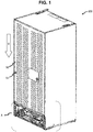
Fig. 1 is a perspective view of a household appliance including a member according to the present invention, emphasizing an outer wall with a condensation surface thereof. -
Fig. 2 is a detail from theFig. 1 , emphasizing an exemplary positioning of an exemplary embodiment of the member. -
Fig. 3 is an exploded view partly showing an exemplary embodiment according to the present invention. -
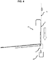
Fig. 4 is a side view showing the relative positioning of several features in an exemplary embodiment according to the present invention. -
Fig. 5 is a perspective view exemplifying several features around a member according to the present invention. -
Fig. 6 is another perspective view showing the positioning of several parts around an exemplary member according to the present invention. -
Fig. 7 is a perspective view of an exemplary drop receiver to be used with a member according to the present invention. -
Fig. 8 is another perspective view of an exemplary drop receiver to be used with a member according to the present invention, emphasizing an exemplary montage of spacer(s) to respective housing(s) thereon. -
Fig. 9 is a detailed perspective view from theFig. 8 , emphasizing an exemplary direction for mounting a spacer to an exemplary housing on a drop receiver. -
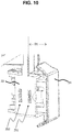
Fig. 10 is a detailed perspective view showing a first engagement position between the spacer and the housing shown in theFig. 9 . -
Fig. 11 is a detailed perspective view showing a further engagement position between the spacer and the housing shown in theFig. 9 . -
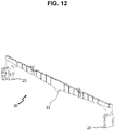
Fig. 12 is a perspective view showing an exemplary drop receiver for use with the member according to the present invention. -
Fig. 13 is a perspective detailed view showing an exemplary housing providing multiple engagement positions for assembly with a spacer. - Referring to the figures summarized above, the present invention proposes a household appliance (100) comprising an outer wall (50) with a condensation surface (51) for formation of condensate from air humidity thereon. The household appliance further comprises a member (10) having a guiding surface (11) adjacent to said condensation surface (51). Said guiding surface (11) is adapted to receive the condensate from the condensation surface (51) in accordance with gravity (g) (i.e. gravity force applied on the condensate); the member (10) further comprises a dripping edge (12) at a side of the guiding surface (11) distal to the outer wall (50). Such dripping edge (12) provides that the member (10) is adapted to allow the condensate drop from the member (10). The condensation may also occur on the guiding surface (11) when the household appliance (100) is in operation.
-
Fig. 1 shows a perspective view of a household appliance (100) including the member (10) according to the present invention, emphasizing an outer wall (50) with a condensation surface (51). The item "A" inFig. 1 corresponds to a portion of the household appliance (100) around its compressor housing (90) for being shown in a close-up view inFig. 2 ; and "g" represents the gravity as a vector quantity. With regard to the operational state of the household appliance (100), the compressor housing (90) is positioned substantially at a lower portion of the household appliance (100). In other words, the compressor housing (90) remains below an outer wall (50, here: rear wall) which has an outer surface (51) substantially parallel to the gravity (g), such that any condensate appeared on the outer surface (51) tend to be guided on the outer surface (51) mainly parallel to the gravity (g). -
Fig. 2 shows a detail from theFig. 1 , emphasizing an exemplary positioning of an exemplary embodiment of the member (10), wherein the member (10) is positioned adjacent to an outer wall (50) (e.g. a rear wall), along their respective edges to directly receive condensate from the condensation surface (51).Fig. 5 is a perspective view from another angle without side walls, insulation, inner lining and front section of the appliance (100). - The member (10) can be considered as a constructional detail which can be named as e.g. "foaming traverse".
- The household appliance (100) can further comprise a drop receiver (20) adapted by its size, shape and position to receive the condensate when dropped from the dripping edge (12).
Fig. 3 shows is an exploded view partly showing an exemplary embodiment according to the present invention, wherein the drop receiver (20) is arranged to remain below the member (10) when in operation to receive condensate therefrom. The shaded items on theFig. 3 represent drops of condensate. -
Fig. 4 shows a side view showing an exemplary positioning between a member (10) and an outer surface (51) of an outer wall (50) in an exemplary embodiment of the household appliance (100) according to the present invention, emphasizing a dripping edge (12), and a drop receiver (20) which is arranged to remain below (at a vertical projection of) the dripping edge (12) when the household appliance is in operation. Due to the gravitation, any condensate formed on the condensation surface (51) is to flow to the guiding surface (11) of the member (10), and to continue towards the dripping edge (12), then to leave the member (10) by dropping onto or being conducted to the drop receiver (20). - The drop receiver (20) can have two distal ends substantially along a length (L) of the dripping edge (12), said length being substantially in a horizontal direction (H) (which is perpendicular to the direction of gravity "g" as emphasized in the
Fig. 3 ) when in use; and the drop receiver (20) can be attached to the member (10) at one or more zone(s) between said distal ends. This embodiment provides secure relative positioning between the dripping edge (12) and the drop receiver (20) against bending of the drop receiver (20) e.g. at assembly of the household appliance (100), which would potentially result in dripping of condensate to any location other than the drop receiver (20). This embodiment is exemplified inFig. 7 andFig. 8 , with two (as an example for one or more) connecting means (28) each corresponding to one of such zones. - The drop receiver (20) can have a shape and size adapted to direct condensate towards an evaporation receptacle (30).
Fig. 6 shows a perspective view showing detail of an exemplary embodiment including an evaporation receptacle (30) for receiving condensate from the drop receiver (20). - In an embodiment to achieve this function, the drop receiver can have one or more inclined portion(s) (21) adapted to provide a horizontal component to a flow of the condensate thereon when in use, said horizontal component being partly or completely directed towards a vertical projection of the evaporation receptacle (30), as schematically exemplified in the
Fig.3 . - The household appliance can further comprise a conduit adapted to further guide the condensate from the drop receiver (20) towards the evaporation receptacle (30) when in use. Schematics of such embodiment is exemplified in the
Fig. 3 . - The evaporation receptacle (30) can be adapted to have a greater temperature than the condensation surface (51) when in operation. This embodiment facilitates and expedite the evaporation of condensate on the evaporation receptacle (30), said evaporation being symbolized over curved, dashed arrows on
Fig. 3 . Accordingly, the evaporation receptacle (30) can be configured to be in heat transfer communication with e.g. a compressor which readily generates heat when in operation thereby having a higher temperature when compared to its surroundings. - The drop receiver (20) can further include one or more housing(s) (23) configured to partly receive respective one or more spacer(s) (24). Such housings (23) are exemplified in
Fig. 6 ,Fig. 7 ,Fig. 12 andFig. 13 before installation of respective spacers (24). - A spacer (24) is configured to, in use, be only partly received by a respective housing (23) thereby leaving a portion thereof extending out of a plane to an extent corresponding to a distance (D, D1 or D2), which plane being substantially defined by the condensation surface (51) of the outer wall (50). As it is available with such nonlimiting design, the spacer(s) (24) are configured to secure one or more pre-determined distance(s) (exemplified as one or more of D, D1, D2) for the outer wall (50) from a further surface substantially parallel to said outer wall (50). Spacer(s) (24) being or to be received by such housing(s) (23) are exemplified in
Fig. 8 ,Fig. 9 (including an exemplary montage direction of a spacer to a housing, symbolized over a thick arrow),Fig. 10 (with a first pre-determined distance D=D1),Fig. 11 (with a further pre-determined distance D=D2 different from D1). - The housing(s) (23) may be formed integral to the drop receiver (20), thereby providing an enhanced mechanical stability for the respective positioning between the housing(s) (23) and the drop receiver (20), e.g. at assembling of the household appliance (100).
- A housing (23) may include one or more lug(s) (26) as exemplified in the
Fig. 13 configured to limit the penetration of a respective spacer (24) at introduction thereof into the housing (23), thereby preventing the spacer (24) being completely received by the housing (23), and further securing that the extent to which the spacer (24) extends out-of said plane is greater than zero. - The one or more housing(s) (23) or respective one or more spacer(s) (24) can include multiple engagement positions (251, 252) in a direction substantially perpendicular to the outer wall (50). This embodiment enables selection of such distance from multiple options, such that a more suitable distance between the outer wall (50) and the further surface can be selected from other option(s) in accordance with the climatic requirements (and psychrometric values including air humidity, temperature and pressure) determining a tendency for condensation and a condensation rate on the condensation surface (51) when the household appliance (100) is in operation.
Fig. 10 exemplifies provision of a first pre-determined distance (D=D1) by fixing a spacer (24) to a respective housing (23) at a first engagement position (251); whereasFig. 11 exemplifies provision of a further pre-determined distance (D=D2 which is different from D1) by fixing the spacer (24) to the respective housing (23) at a further engagement position (252, which is different from the first engagement position 251). - As exemplified over detailed views in the
Fig. 9 ,Fig. 10 andFig. 11 , a housing (23) and spacer (24) may be configured to be engaged over snap-fit connection therebetween. To this end, a housing (23) may be provided with one or more slit(s) determining respective engagement position(s) (251, 252); and a respective spacer (24) may be provided with a flexible protrusion (27) configured to engage with either one of said slit(s) thereby securing a respective distance (D, e.g. D1 or D2). - The member (10) can be substantially formed from a non-flammable material. Such non-flammable material can be selected in accordance with the international standard IEC 60235-2-24 (e.g. the version thereof valid as of the date of filing of the present application), such that the material meets the requirements of said standard. This embodiment can correspond to that the member (10) can be substantially formed from a thermally stable, inflammable material, for example from a non-flammable polymeric material or from a metallic material, for example steel or aluminum.
- Accordingly, the member (10) can be substantially formed from a metallic material. As a result, also the dripping edge (12) in this embodiment, can be substantially formed from metallic material, and thereby provide an increased resistance and rigidity against any deflexion of the member (10), especially against deflection caused by volumetric expansion of insulation material at conversion thereof into a foam.
- In an embodiment, the member (10) may be substantially formed from bent sheet metal. The exemplary member (10) side section view of which is shown in the
Fig. 4 can be obtained from a sheet metal. In this example, the dripping edge (12) can be formed by bending the sheet metal to about 180° (taking 360° as full angle) with respect to zone to be corresponding to a guiding surface (11) thereon; and then further bending the sheet metal around a line mainly parallel to the dripping edge (12) in opposite direction to about 90-100°, the dripping edge (12) remaining between said line and the guiding surface (11). - The household appliance (100) according to the present invention may be a cooling appliance. Accordingly the household appliance (100) may be a refrigerator; or alternatively, the household appliance (100) may be an air conditioner.
- The present invention provides management of condensation by conducting the condensate away from delicate electronics in the compressor housing (90), such that condensate cannot reach to the electronics. The present invention further provides elimination of mold formation on outer walls (50) of the household appliance (100) by conducting the condensate away. Thus, the above mentioned problems are solved, with the cooling appliance (100) according to the present invention.
-
- 10
- member
- 11
- guiding surface
- 12
- dripping edge
- 20
- drop receiver
- 21
- inclined portion
- 22
- conduit
- 23
- housing
- 24
- spacer
- 251, 252
- engagement position(s)
- 26
- lug
- 27
- protrusion
- 28
- connecting means
- 30
- evaporation receptacle
- 50
- outer wall
- 51
- condensation surface
- 90
- compressor housing
- 100
- household appliance
- g
- gravity
Claims (15)
- A household appliance (100) comprising an outer wall (50) with a condensation surface (51) for formation of condensate from air humidity thereon; wherein the household appliance further comprises a member (10) having a guiding surface (11) adjacent to said condensation surface (51), adapted to receive the condensate from the condensation surface (51) in accordance with gravity (g); the member (10) further comprises a dripping edge (12) at a side of the guiding surface (11) distal to the outer wall (50).
- The household appliance according to the claim 1, further comprising a drop receiver (20) adapted by its size, shape and position to receive the condensate when dropped from the dripping edge (12).
- The household appliance according to the claim 2, wherein the drop receiver (20) has two distal ends substantially along a length (L) of the dripping edge (12), said length being substantially in a horizontal direction when in use; and wherein the drop receiver (20) is attached to the member (10) at one or more zone(s) between said distal ends.
- The household appliance according to any one of the claims 2 or 3, wherein the drop receiver (20) has a shape and size adapted to direct the condensate towards an evaporation receptacle (30).
- The household appliance according to the claim 4, wherein the drop receiver (20) has one or more inclined portion(s) (21) adapted to provide a horizontal component to a flow of the condensate thereon when in use, said horizontal component being at least partly directed towards a vertical projection of the evaporation receptacle (30).
- The household appliance according to any one of the claims 5, further comprising a conduit (22) adapted to further guide the condensate from the drop receiver (20) towards the evaporation receptacle (30) when in use.
- The household appliance according to any one of the claims 4 to 6, wherein the evaporation receptacle (30) is adapted to have a greater temperature than the condensation surface (51) when in operation.
- The household appliance according to any one of the claims 2 to 7, wherein the drop receiver (20) further includes one or more housing(s) (23) configured to partly receive respective one or more spacer(s) (24) configured to, in use, secure one or more pre-determined distance(s) for the outer wall (50) from a further surface substantially parallel thereto.
- The household appliance according to the claim 8, wherein the one or more housing(s) (23) or respective one or more spacer(s) (24) include multiple engagement positions (251, 252) in a direction substantially perpendicular to the outer wall (50).
- The household appliance according to any one of the claims 1 to 9, wherein the member (10) is substantially formed from a non-flammable material.
- The household appliance according to the claim 10, wherein the member (10) is substantially formed from a metallic material.
- The household appliance according to the claim 11, wherein the member (10) is substantially formed from bent sheet metal.
- The household appliance according to any one of the claims 1 to 12, being a cooling appliance.
- The household appliance according to the claim 13, being a refrigerator.
- The household appliance according to the claim 13, being an air conditioner.
Priority Applications (1)
| Application Number | Priority Date | Filing Date | Title |
|---|---|---|---|
| PL19160965T PL3546858T3 (en) | 2018-03-27 | 2019-03-06 | A household appliance with a condensation dripping edge |
Applications Claiming Priority (1)
| Application Number | Priority Date | Filing Date | Title |
|---|---|---|---|
| TR201804275 | 2018-03-27 |
Publications (2)
| Publication Number | Publication Date |
|---|---|
| EP3546858A1 true EP3546858A1 (en) | 2019-10-02 |
| EP3546858B1 EP3546858B1 (en) | 2020-11-18 |
Family
ID=65717857
Family Applications (1)
| Application Number | Title | Priority Date | Filing Date |
|---|---|---|---|
| EP19160965.0A Active EP3546858B1 (en) | 2018-03-27 | 2019-03-06 | A household appliance with a condensation dripping edge |
Country Status (3)
| Country | Link |
|---|---|
| EP (1) | EP3546858B1 (en) |
| CN (1) | CN110307686B (en) |
| PL (1) | PL3546858T3 (en) |
Cited By (1)
| Publication number | Priority date | Publication date | Assignee | Title |
|---|---|---|---|---|
| DE102021134065A1 (en) | 2021-12-21 | 2023-06-22 | Liebherr-Hausgeräte Ochsenhausen GmbH | refrigerator and/or freezer |
Citations (13)
| Publication number | Priority date | Publication date | Assignee | Title |
|---|---|---|---|---|
| JPS6011031A (en) * | 1983-07-01 | 1985-01-21 | Matsushita Electric Ind Co Ltd | Air conditioner dew treatment equipment |
| JPS6149284U (en) * | 1984-08-31 | 1986-04-02 | ||
| JPH02287081A (en) * | 1989-04-27 | 1990-11-27 | Sanyo Electric Co Ltd | Show case |
| GB2258297A (en) | 1991-07-03 | 1993-02-03 | Candy Spa | Preformed assembly for defining the compressor space in refrigerators |
| JPH0650651A (en) * | 1992-07-31 | 1994-02-25 | Sanyo Electric Co Ltd | Low temperature display case |
| JP2000258043A (en) * | 1999-03-08 | 2000-09-22 | Hoshizaki Electric Co Ltd | Vapor pan of device having refrigerating mechanism |
| JP2001201240A (en) * | 2000-01-17 | 2001-07-27 | Sanyo Electric Co Ltd | Storage case |
| JP2004239474A (en) * | 2003-02-04 | 2004-08-26 | Hoshizaki Electric Co Ltd | Dew condensation water draining structure for showcase |
| EP1880644A1 (en) * | 2006-07-19 | 2008-01-23 | Sanyo Electric Co., Ltd. | Low-temperature showcase |
| JP2008173375A (en) * | 2007-01-22 | 2008-07-31 | Okamura Corp | Open showcase |
| EP2295899A1 (en) * | 2009-08-21 | 2011-03-16 | BSH Bosch und Siemens Hausgeräte GmbH | Cooler with thawed water collecting channel |
| JP2017003143A (en) * | 2015-06-05 | 2017-01-05 | 東芝ライフスタイル株式会社 | refrigerator |
| EP3147604A1 (en) * | 2015-09-25 | 2017-03-29 | BSH Hausgeräte GmbH | Method for producing a household refrigerator with specifically reinforced rear wall and household refrigerator |
Family Cites Families (2)
| Publication number | Priority date | Publication date | Assignee | Title |
|---|---|---|---|---|
| CN204165306U (en) * | 2014-10-20 | 2015-02-18 | 河南鸿昌电子有限公司 | There is the semi-conductor cooling box of drip tray |
| CN106322564A (en) * | 2015-06-30 | 2017-01-11 | 淄博气宇空调节能设备有限公司 | Water pan of combined type air-conditioning unit |
-
2019
- 2019-03-06 EP EP19160965.0A patent/EP3546858B1/en active Active
- 2019-03-06 PL PL19160965T patent/PL3546858T3/en unknown
- 2019-03-25 CN CN201910227371.6A patent/CN110307686B/en active Active
Patent Citations (13)
| Publication number | Priority date | Publication date | Assignee | Title |
|---|---|---|---|---|
| JPS6011031A (en) * | 1983-07-01 | 1985-01-21 | Matsushita Electric Ind Co Ltd | Air conditioner dew treatment equipment |
| JPS6149284U (en) * | 1984-08-31 | 1986-04-02 | ||
| JPH02287081A (en) * | 1989-04-27 | 1990-11-27 | Sanyo Electric Co Ltd | Show case |
| GB2258297A (en) | 1991-07-03 | 1993-02-03 | Candy Spa | Preformed assembly for defining the compressor space in refrigerators |
| JPH0650651A (en) * | 1992-07-31 | 1994-02-25 | Sanyo Electric Co Ltd | Low temperature display case |
| JP2000258043A (en) * | 1999-03-08 | 2000-09-22 | Hoshizaki Electric Co Ltd | Vapor pan of device having refrigerating mechanism |
| JP2001201240A (en) * | 2000-01-17 | 2001-07-27 | Sanyo Electric Co Ltd | Storage case |
| JP2004239474A (en) * | 2003-02-04 | 2004-08-26 | Hoshizaki Electric Co Ltd | Dew condensation water draining structure for showcase |
| EP1880644A1 (en) * | 2006-07-19 | 2008-01-23 | Sanyo Electric Co., Ltd. | Low-temperature showcase |
| JP2008173375A (en) * | 2007-01-22 | 2008-07-31 | Okamura Corp | Open showcase |
| EP2295899A1 (en) * | 2009-08-21 | 2011-03-16 | BSH Bosch und Siemens Hausgeräte GmbH | Cooler with thawed water collecting channel |
| JP2017003143A (en) * | 2015-06-05 | 2017-01-05 | 東芝ライフスタイル株式会社 | refrigerator |
| EP3147604A1 (en) * | 2015-09-25 | 2017-03-29 | BSH Hausgeräte GmbH | Method for producing a household refrigerator with specifically reinforced rear wall and household refrigerator |
Cited By (1)
| Publication number | Priority date | Publication date | Assignee | Title |
|---|---|---|---|---|
| DE102021134065A1 (en) | 2021-12-21 | 2023-06-22 | Liebherr-Hausgeräte Ochsenhausen GmbH | refrigerator and/or freezer |
Also Published As
| Publication number | Publication date |
|---|---|
| EP3546858B1 (en) | 2020-11-18 |
| CN110307686B (en) | 2022-05-06 |
| PL3546858T3 (en) | 2021-05-17 |
| CN110307686A (en) | 2019-10-08 |
Similar Documents
| Publication | Publication Date | Title |
|---|---|---|
| CN105627657B (en) | refrigerator | |
| JP6708697B2 (en) | Removable electric grill with mounting members | |
| EP3546858B1 (en) | A household appliance with a condensation dripping edge | |
| CN102472510A (en) | Outdoor unit | |
| KR20260004289A (en) | Vacuum adiabatic body and refrigerator | |
| EP2772693B1 (en) | Encasing for household appliances | |
| CN102822603B (en) | Heating cooking device | |
| JP5616181B2 (en) | Fixture | |
| CN108036493B (en) | Housing components of air conditioners and air conditioners | |
| CN205980232U (en) | Motor protective cover with press pipe and manger plate function | |
| EP2801782B1 (en) | Heat exchange unit and method for manufacturing a heat exchange unit | |
| CN109631479B (en) | Domestic refrigeration appliance with a covering device for the gap between a foam rail and an electronics cabinet | |
| CN216924736U (en) | Gas water heater | |
| CN104296355A (en) | Air conditioner and shell thereof | |
| CN106152671B (en) | Domestic refrigeration device and method for producing and equipping a domestic refrigeration device | |
| EP3492849B1 (en) | A cooling appliance with a guide for insulation material | |
| JP2012202616A (en) | Outdoor unit | |
| US20180142940A1 (en) | Home Appliance Device Comprising A Door And Home Appliance Device | |
| CN107965966A (en) | No-frost refrigeration device | |
| CN106969550A (en) | Evaporator assemblies and the air conditioner room unit with it | |
| CN101688722A (en) | Housing for a refrigerator device | |
| CN212132721U (en) | Protective cover assembly, air condensing units and air conditioner | |
| EP1891377B1 (en) | A cooking device with terminal box | |
| KR20210061291A (en) | Bore Adjustable Pipe Insulation Material | |
| CN111947385B (en) | Flow guiding device and air-cooled refrigeration equipment with same |
Legal Events
| Date | Code | Title | Description |
|---|---|---|---|
| PUAI | Public reference made under article 153(3) epc to a published international application that has entered the european phase |
Free format text: ORIGINAL CODE: 0009012 |
|
| STAA | Information on the status of an ep patent application or granted ep patent |
Free format text: STATUS: THE APPLICATION HAS BEEN PUBLISHED |
|
| AK | Designated contracting states |
Kind code of ref document: A1 Designated state(s): AL AT BE BG CH CY CZ DE DK EE ES FI FR GB GR HR HU IE IS IT LI LT LU LV MC MK MT NL NO PL PT RO RS SE SI SK SM TR |
|
| AX | Request for extension of the european patent |
Extension state: BA ME |
|
| STAA | Information on the status of an ep patent application or granted ep patent |
Free format text: STATUS: REQUEST FOR EXAMINATION WAS MADE |
|
| 17P | Request for examination filed |
Effective date: 20200402 |
|
| RBV | Designated contracting states (corrected) |
Designated state(s): AL AT BE BG CH CY CZ DE DK EE ES FI FR GB GR HR HU IE IS IT LI LT LU LV MC MK MT NL NO PL PT RO RS SE SI SK SM TR |
|
| GRAP | Despatch of communication of intention to grant a patent |
Free format text: ORIGINAL CODE: EPIDOSNIGR1 |
|
| STAA | Information on the status of an ep patent application or granted ep patent |
Free format text: STATUS: GRANT OF PATENT IS INTENDED |
|
| RIC1 | Information provided on ipc code assigned before grant |
Ipc: F25D 21/14 20060101AFI20200612BHEP |
|
| INTG | Intention to grant announced |
Effective date: 20200710 |
|
| GRAS | Grant fee paid |
Free format text: ORIGINAL CODE: EPIDOSNIGR3 |
|
| GRAA | (expected) grant |
Free format text: ORIGINAL CODE: 0009210 |
|
| STAA | Information on the status of an ep patent application or granted ep patent |
Free format text: STATUS: THE PATENT HAS BEEN GRANTED |
|
| AK | Designated contracting states |
Kind code of ref document: B1 Designated state(s): AL AT BE BG CH CY CZ DE DK EE ES FI FR GB GR HR HU IE IS IT LI LT LU LV MC MK MT NL NO PL PT RO RS SE SI SK SM TR |
|
| REG | Reference to a national code |
Ref country code: GB Ref legal event code: FG4D |
|
| REG | Reference to a national code |
Ref country code: CH Ref legal event code: EP |
|
| REG | Reference to a national code |
Ref country code: IE Ref legal event code: FG4D |
|
| REG | Reference to a national code |
Ref country code: DE Ref legal event code: R096 Ref document number: 602019001325 Country of ref document: DE |
|
| REG | Reference to a national code |
Ref country code: AT Ref legal event code: REF Ref document number: 1336214 Country of ref document: AT Kind code of ref document: T Effective date: 20201215 |
|
| REG | Reference to a national code |
Ref country code: AT Ref legal event code: MK05 Ref document number: 1336214 Country of ref document: AT Kind code of ref document: T Effective date: 20201118 |
|
| REG | Reference to a national code |
Ref country code: NL Ref legal event code: MP Effective date: 20201118 |
|
| PG25 | Lapsed in a contracting state [announced via postgrant information from national office to epo] |
Ref country code: GR Free format text: LAPSE BECAUSE OF FAILURE TO SUBMIT A TRANSLATION OF THE DESCRIPTION OR TO PAY THE FEE WITHIN THE PRESCRIBED TIME-LIMIT Effective date: 20210219 Ref country code: NO Free format text: LAPSE BECAUSE OF FAILURE TO SUBMIT A TRANSLATION OF THE DESCRIPTION OR TO PAY THE FEE WITHIN THE PRESCRIBED TIME-LIMIT Effective date: 20210218 Ref country code: PT Free format text: LAPSE BECAUSE OF FAILURE TO SUBMIT A TRANSLATION OF THE DESCRIPTION OR TO PAY THE FEE WITHIN THE PRESCRIBED TIME-LIMIT Effective date: 20210318 Ref country code: RS Free format text: LAPSE BECAUSE OF FAILURE TO SUBMIT A TRANSLATION OF THE DESCRIPTION OR TO PAY THE FEE WITHIN THE PRESCRIBED TIME-LIMIT Effective date: 20201118 Ref country code: FI Free format text: LAPSE BECAUSE OF FAILURE TO SUBMIT A TRANSLATION OF THE DESCRIPTION OR TO PAY THE FEE WITHIN THE PRESCRIBED TIME-LIMIT Effective date: 20201118 |
|
| PG25 | Lapsed in a contracting state [announced via postgrant information from national office to epo] |
Ref country code: BG Free format text: LAPSE BECAUSE OF FAILURE TO SUBMIT A TRANSLATION OF THE DESCRIPTION OR TO PAY THE FEE WITHIN THE PRESCRIBED TIME-LIMIT Effective date: 20210218 Ref country code: LV Free format text: LAPSE BECAUSE OF FAILURE TO SUBMIT A TRANSLATION OF THE DESCRIPTION OR TO PAY THE FEE WITHIN THE PRESCRIBED TIME-LIMIT Effective date: 20201118 Ref country code: IS Free format text: LAPSE BECAUSE OF FAILURE TO SUBMIT A TRANSLATION OF THE DESCRIPTION OR TO PAY THE FEE WITHIN THE PRESCRIBED TIME-LIMIT Effective date: 20210318 Ref country code: SE Free format text: LAPSE BECAUSE OF FAILURE TO SUBMIT A TRANSLATION OF THE DESCRIPTION OR TO PAY THE FEE WITHIN THE PRESCRIBED TIME-LIMIT Effective date: 20201118 Ref country code: AT Free format text: LAPSE BECAUSE OF FAILURE TO SUBMIT A TRANSLATION OF THE DESCRIPTION OR TO PAY THE FEE WITHIN THE PRESCRIBED TIME-LIMIT Effective date: 20201118 |
|
| REG | Reference to a national code |
Ref country code: LT Ref legal event code: MG9D |
|
| PG25 | Lapsed in a contracting state [announced via postgrant information from national office to epo] |
Ref country code: HR Free format text: LAPSE BECAUSE OF FAILURE TO SUBMIT A TRANSLATION OF THE DESCRIPTION OR TO PAY THE FEE WITHIN THE PRESCRIBED TIME-LIMIT Effective date: 20201118 |
|
| PG25 | Lapsed in a contracting state [announced via postgrant information from national office to epo] |
Ref country code: CZ Free format text: LAPSE BECAUSE OF FAILURE TO SUBMIT A TRANSLATION OF THE DESCRIPTION OR TO PAY THE FEE WITHIN THE PRESCRIBED TIME-LIMIT Effective date: 20201118 Ref country code: SM Free format text: LAPSE BECAUSE OF FAILURE TO SUBMIT A TRANSLATION OF THE DESCRIPTION OR TO PAY THE FEE WITHIN THE PRESCRIBED TIME-LIMIT Effective date: 20201118 Ref country code: SK Free format text: LAPSE BECAUSE OF FAILURE TO SUBMIT A TRANSLATION OF THE DESCRIPTION OR TO PAY THE FEE WITHIN THE PRESCRIBED TIME-LIMIT Effective date: 20201118 Ref country code: EE Free format text: LAPSE BECAUSE OF FAILURE TO SUBMIT A TRANSLATION OF THE DESCRIPTION OR TO PAY THE FEE WITHIN THE PRESCRIBED TIME-LIMIT Effective date: 20201118 Ref country code: RO Free format text: LAPSE BECAUSE OF FAILURE TO SUBMIT A TRANSLATION OF THE DESCRIPTION OR TO PAY THE FEE WITHIN THE PRESCRIBED TIME-LIMIT Effective date: 20201118 Ref country code: LT Free format text: LAPSE BECAUSE OF FAILURE TO SUBMIT A TRANSLATION OF THE DESCRIPTION OR TO PAY THE FEE WITHIN THE PRESCRIBED TIME-LIMIT Effective date: 20201118 |
|
| REG | Reference to a national code |
Ref country code: DE Ref legal event code: R097 Ref document number: 602019001325 Country of ref document: DE |
|
| PG25 | Lapsed in a contracting state [announced via postgrant information from national office to epo] |
Ref country code: DK Free format text: LAPSE BECAUSE OF FAILURE TO SUBMIT A TRANSLATION OF THE DESCRIPTION OR TO PAY THE FEE WITHIN THE PRESCRIBED TIME-LIMIT Effective date: 20201118 |
|
| PLBE | No opposition filed within time limit |
Free format text: ORIGINAL CODE: 0009261 |
|
| STAA | Information on the status of an ep patent application or granted ep patent |
Free format text: STATUS: NO OPPOSITION FILED WITHIN TIME LIMIT |
|
| 26N | No opposition filed |
Effective date: 20210819 |
|
| PG25 | Lapsed in a contracting state [announced via postgrant information from national office to epo] |
Ref country code: MC Free format text: LAPSE BECAUSE OF FAILURE TO SUBMIT A TRANSLATION OF THE DESCRIPTION OR TO PAY THE FEE WITHIN THE PRESCRIBED TIME-LIMIT Effective date: 20201118 Ref country code: NL Free format text: LAPSE BECAUSE OF FAILURE TO SUBMIT A TRANSLATION OF THE DESCRIPTION OR TO PAY THE FEE WITHIN THE PRESCRIBED TIME-LIMIT Effective date: 20201118 Ref country code: AL Free format text: LAPSE BECAUSE OF FAILURE TO SUBMIT A TRANSLATION OF THE DESCRIPTION OR TO PAY THE FEE WITHIN THE PRESCRIBED TIME-LIMIT Effective date: 20201118 |
|
| PG25 | Lapsed in a contracting state [announced via postgrant information from national office to epo] |
Ref country code: SI Free format text: LAPSE BECAUSE OF FAILURE TO SUBMIT A TRANSLATION OF THE DESCRIPTION OR TO PAY THE FEE WITHIN THE PRESCRIBED TIME-LIMIT Effective date: 20201118 |
|
| REG | Reference to a national code |
Ref country code: BE Ref legal event code: MM Effective date: 20210331 |
|
| PG25 | Lapsed in a contracting state [announced via postgrant information from national office to epo] |
Ref country code: ES Free format text: LAPSE BECAUSE OF FAILURE TO SUBMIT A TRANSLATION OF THE DESCRIPTION OR TO PAY THE FEE WITHIN THE PRESCRIBED TIME-LIMIT Effective date: 20201118 Ref country code: FR Free format text: LAPSE BECAUSE OF NON-PAYMENT OF DUE FEES Effective date: 20210331 Ref country code: LU Free format text: LAPSE BECAUSE OF NON-PAYMENT OF DUE FEES Effective date: 20210306 Ref country code: IE Free format text: LAPSE BECAUSE OF NON-PAYMENT OF DUE FEES Effective date: 20210306 |
|
| PG25 | Lapsed in a contracting state [announced via postgrant information from national office to epo] |
Ref country code: IS Free format text: LAPSE BECAUSE OF FAILURE TO SUBMIT A TRANSLATION OF THE DESCRIPTION OR TO PAY THE FEE WITHIN THE PRESCRIBED TIME-LIMIT Effective date: 20210318 |
|
| PG25 | Lapsed in a contracting state [announced via postgrant information from national office to epo] |
Ref country code: BE Free format text: LAPSE BECAUSE OF NON-PAYMENT OF DUE FEES Effective date: 20210331 |
|
| REG | Reference to a national code |
Ref country code: CH Ref legal event code: PL |
|
| PG25 | Lapsed in a contracting state [announced via postgrant information from national office to epo] |
Ref country code: LI Free format text: LAPSE BECAUSE OF NON-PAYMENT OF DUE FEES Effective date: 20220331 Ref country code: CH Free format text: LAPSE BECAUSE OF NON-PAYMENT OF DUE FEES Effective date: 20220331 |
|
| PG25 | Lapsed in a contracting state [announced via postgrant information from national office to epo] |
Ref country code: CY Free format text: LAPSE BECAUSE OF FAILURE TO SUBMIT A TRANSLATION OF THE DESCRIPTION OR TO PAY THE FEE WITHIN THE PRESCRIBED TIME-LIMIT Effective date: 20201118 |
|
| PG25 | Lapsed in a contracting state [announced via postgrant information from national office to epo] |
Ref country code: HU Free format text: LAPSE BECAUSE OF FAILURE TO SUBMIT A TRANSLATION OF THE DESCRIPTION OR TO PAY THE FEE WITHIN THE PRESCRIBED TIME-LIMIT; INVALID AB INITIO Effective date: 20190306 |
|
| PGFP | Annual fee paid to national office [announced via postgrant information from national office to epo] |
Ref country code: IT Payment date: 20230331 Year of fee payment: 5 |
|
| GBPC | Gb: european patent ceased through non-payment of renewal fee |
Effective date: 20230306 |
|
| PG25 | Lapsed in a contracting state [announced via postgrant information from national office to epo] |
Ref country code: GB Free format text: LAPSE BECAUSE OF NON-PAYMENT OF DUE FEES Effective date: 20230306 |
|
| PG25 | Lapsed in a contracting state [announced via postgrant information from national office to epo] |
Ref country code: GB Free format text: LAPSE BECAUSE OF NON-PAYMENT OF DUE FEES Effective date: 20230306 |
|
| PG25 | Lapsed in a contracting state [announced via postgrant information from national office to epo] |
Ref country code: MK Free format text: LAPSE BECAUSE OF FAILURE TO SUBMIT A TRANSLATION OF THE DESCRIPTION OR TO PAY THE FEE WITHIN THE PRESCRIBED TIME-LIMIT Effective date: 20201118 |
|
| PG25 | Lapsed in a contracting state [announced via postgrant information from national office to epo] |
Ref country code: MT Free format text: LAPSE BECAUSE OF FAILURE TO SUBMIT A TRANSLATION OF THE DESCRIPTION OR TO PAY THE FEE WITHIN THE PRESCRIBED TIME-LIMIT Effective date: 20201118 |
|
| PG25 | Lapsed in a contracting state [announced via postgrant information from national office to epo] |
Ref country code: IT Free format text: LAPSE BECAUSE OF NON-PAYMENT OF DUE FEES Effective date: 20240306 |
|
| PGFP | Annual fee paid to national office [announced via postgrant information from national office to epo] |
Ref country code: DE Payment date: 20260331 Year of fee payment: 8 |
|
| PGFP | Annual fee paid to national office [announced via postgrant information from national office to epo] |
Ref country code: TR Payment date: 20260227 Year of fee payment: 8 |
|
| PGFP | Annual fee paid to national office [announced via postgrant information from national office to epo] |
Ref country code: PL Payment date: 20260227 Year of fee payment: 8 |